

Page 1

Handbook
Handbook
OPTISENS MAC 100
OPTISENS MAC 100
OPTISENS MAC 100OPTISENS MAC 100
HandbookHandbook
Multiparameter signal converter
Electronic Revision: ER 1.0.0
The documentation is only complete when used in combination with the relevant
documentation for the sensor.
© KROHNE 04/2011 - MA OPTISENS MAC 100 R01 en
Page 2

: IMPRINT :::::::::::::::::::::::::::::::::::::::
All rights reserved. It is prohibited to reproduce this documentation, or any part thereof, without
the prior written authorisation of KROHNE Messtechnik GmbH.
Subject to change without notice.
Copyright 2011 by
KROHNE Messtechnik GmbH - Ludwig-Krohne-Str. 5 - 47058 Duisburg (Germany)
2
www.krohne.com 04/2011 - MA OPTISENS MAC 100 R01 en
Page 3

OPTISENS MAC 100
CONTENTS
1 Safety instructions 6
1.1 Software history ............................................................................................................... 6
1.2 Intended use ..................................................................................................................... 7
1.3 Certifications .................................................................................................................... 7
1.4 Safety instructions from the manufacturer ..................................................................... 8
1.4.1 Copyright and data protection ................................................................................................ 8
1.4.2 Disclaimer ............................................................................................................................... 8
1.4.3 Product liability and warranty ................................................................................................ 9
1.4.4 Information concerning the documentation........................................................................... 9
1.4.5 Warnings and symbols used................................................................................................. 10
1.5 Safety instructions for the operator............................................................................... 11
2 Device description 12
2.1 Scope of delivery............................................................................................................. 12
2.2 Device description .......................................................................................................... 13
2.3 Sensor input combinations............................................................................................. 15
2.4 Nameplate ...................................................................................................................... 16
3 Installation 17
3.1 Notes on installation ......................................................................................................17
3.2 Storage and transport .................................................................................................... 17
3.3 Wall mounting ................................................................................................................ 17
4 Electrical connections 20
4.1 Safety instructions.......................................................................................................... 20
4.2 Used abbreviations .........................................................................................................20
4.3 Important device-specific notes on electrical connection............................................. 21
4.4 Opening the converter housing ...................................................................................... 22
4.5 Overview of the terminal compartment ......................................................................... 22
4.6 Connecting the signal cables ......................................................................................... 23
4.7 Connecting the power supply......................................................................................... 23
4.8 Description and properties of the outputs and the input............................................... 25
4.8.1 Current output ...................................................................................................................... 25
4.8.2 Relay outputs ........................................................................................................................ 25
4.8.3 Control input (passive) .......................................................................................................... 26
4.9 Connection diagrams of the outputs and the input ....................................................... 27
4.9.1 Important notes..................................................................................................................... 27
4.9.2 Description of electrical symbols ......................................................................................... 27
4.9.3 Block diagram....................................................................................................................... 28
4.9.4 Current output (active).......................................................................................................... 28
4.9.5 Relay outputs ........................................................................................................................ 29
4.9.6 Control input ......................................................................................................................... 29
4.10 Electrical connection of the outputs and the input...................................................... 30
4.10.1 Connecting the current outputs..........................................................................................30
4.10.2 Connecting the relay outputs.............................................................................................. 31
www.krohne.com04/2011 - MA OPTISENS MAC 100 R01 en
3
Page 4

CONTENTS
OPTISENS MAC 100
5 Start-up 34
5.1 Switching on the power .................................................................................................. 34
6 Operation 36
6.1 Operating elements........................................................................................................ 36
6.2 Measuring mode.............................................................................................................37
6.2.1 First measuring page............................................................................................................ 37
6.2.2 Second measuring page ....................................................................................................... 39
6.2.3 Status page ........................................................................................................................... 40
6.2.4 Trend diagram....................................................................................................................... 41
6.3 Menu mode ..................................................................................................................... 41
6.3.1 Navigating through the menus .............................................................................................42
6.3.2 Menu "quick setup"............................................................................................................... 46
6.4 Menu mode structure..................................................................................................... 47
6.5 Function tables ............................................................................................................... 50
6.5.1 Menu A, quick setup.............................................................................................................. 50
6.5.2 Menu B, test .......................................................................................................................... 52
6.5.3 Menu C, setup ....................................................................................................................... 54
6.5.4 Menu D, service..................................................................................................................... 59
6.6 Functions in detail .......................................................................................................... 60
6.6.1 Manual hold........................................................................................................................... 60
6.6.2 Simulation of measured values ............................................................................................60
6.6.3 Status log and calibration log ............................................................................................... 61
6.6.4 Error current of current output............................................................................................ 62
6.6.5 Overflow sign and exponential format.................................................................................. 63
6.6.6 Save settings .........................................................................................................................65
6.6.7 Load settings......................................................................................................................... 65
6.6.8 Passwords............................................................................................................................. 66
6.7 Status messages and diagnostic information................................................................ 66
6.7.1 Error category "Device failure" (bold "F")............................................................................ 68
6.7.2 Error category "Application error" ( "F", not bold) .............................................................. 69
6.7.3 Error category "Out of specification" (S) .............................................................................. 69
6.7.4 Error category "Check request" or "Run check" (C) ............................................................ 70
6.7.5 Error category "Information" (I) ........................................................................................... 70
6.8 Timeout function............................................................................................................. 71
7 Service 72
7.1 Maintenance and repair ................................................................................................. 72
7.2 Spare parts availability...................................................................................................72
7.3 Availability of services .................................................................................................... 72
7.4 Returning the device to the manufacturer..................................................................... 73
7.4.1 General information.............................................................................................................. 73
7.4.2 Form (for copying) to accompany a returned device............................................................ 74
7.5 Disposal .......................................................................................................................... 74
4
www.krohne.com 04/2011 - MA OPTISENS MAC 100 R01 en
Page 5

OPTISENS MAC 100
CONTENTS
8 Technical data 75
8.1 Measuring principle........................................................................................................75
8.2 Technical data table .......................................................................................................75
8.3 Dimensions and weight .................................................................................................. 79
8.3.1 Housing ................................................................................................................................. 79
8.3.2 Mounting plate ...................................................................................................................... 80
9 Notes 81
www.krohne.com04/2011 - MA OPTISENS MAC 100 R01 en
5
Page 6

1 SAFETY INSTRUCTIONS
1.1 Software history
The "Electronic Revision" (ER) is consulted to document the revision status of electronic
equipment according to NE 53 for all GDC devices. It is easy to see from the ER whether
troubleshooting or larger changes in the electronic equipment have taken place and how that
has affected the compatibility.
Changes and effect on compatibility
1 Downwards compatible changes and fault repair with no effect on operation (e.g. spelling
mistakes on display)
2-_ Downwards compatible hardware and/or software change of interfaces:
HART
®
H
P PROFIBUS
F Foundation Fieldbus
M Modbus
X all interfaces
3-_ Downwards compatible hardware and/or software change of inputs and outputs:
I Current output
F, P Frequency / pulse output
S Status output
C Control input
CI Current input
X all inputs and outputs
4 Downwards compatible changes with new functions
5 Incompatible changes, i.e. electronic equipment must be changed.
OPTISENS MAC 100
INFORMATION!
In the table below, "x" is a placeholder for possible multi-digit alphanumeric combinations,
depending on the available version.
Release date Electronic Revision Changes and
Documentation
compatibility
2007-12-11 ER 1.0.0 - MA MAC 100 R01
6
www.krohne.com 04/2011 - MA OPTISENS MAC 100 R01 en
Page 7

OPTISENS MAC 100
1.2 Intended use
DANGER!
Never install or operate the device in potentially explosive areas, it might cause an explosion that
can result in fatal injuries.
WARNING!
If the device is not used according to the operating conditions (refer to chapter "Technical data"),
the intended protection could be affected.
In combination with the different sensors of the OPTISENS 1000 series the MAC 100 measures
analytical parameters in water and waste water applications.
1.3 Certifications
DANGER!
Never install or operate the device in potentially explosive areas, it might cause an explosion that
can result in fatal injuries.
SAFETY INSTRUCTIONS 1
CE marking
The device fulfils the statutory requirements of the following EC directives:
• Low Voltage Directive 2006/95/EC
• EMC Directive 2004/108/EC
as well as
• EN 61010
• EMC specification acc. to EN 61326/A1
• NAMUR recommendations NE 21 and NE 43
www.krohne.com04/2011 - MA OPTISENS MAC 100 R01 en
7
Page 8

1 SAFETY INSTRUCTIONS
1.4 Safety instructions from the manufacturer
1.4.1 Copyright and data protection
The contents of this document have been created with great care. Nevertheless, we provide no
guarantee that the contents are correct, complete or up-to-date.
The contents and works in this document are subject to copyright. Contributions from third
parties are identified as such. Reproduction, processing, dissemination and any type of use
beyond what is permitted under copyright requires written authorisation from the respective
author and/or the manufacturer.
The manufacturer tries always to observe the copyrights of others, and to draw on works created
in-house or works in the public domain.
The collection of personal data (such as names, street addresses or e-mail addresses) in the
manufacturer's documents is always on a voluntary basis whenever possible. Whenever
feasible, it is always possible to make use of the offerings and services without providing any
personal data.
OPTISENS MAC 100
We draw your attention to the fact that data transmission over the Internet (e.g. when
communicating by e-mail) may involve gaps in security. It is not possible to protect such data
completely against access by third parties.
We hereby expressly prohibit the use of the contact data published as part of our duty to publish
an imprint for the purpose of sending us any advertising or informational materials that we have
not expressly requested.
1.4.2 Disclaimer
The manufacturer will not be liable for any damage of any kind by using its product, including,
but not limited to direct, indirect or incidental and consequential damages.
This disclaimer does not apply in case the manufacturer has acted on purpose or with gross
negligence. In the event any applicable law does not allow such limitations on implied warranties
or the exclusion of limitation of certain damages, you may, if such law applies to you, not be
subject to some or all of the above disclaimer, exclusions or limitations.
Any product purchased from the manufacturer is warranted in accordance with the relevant
product documentation and our Terms and Conditions of Sale.
The manufacturer reserves the right to alter the content of its documents, including this
disclaimer in any way, at any time, for any reason, without prior notification, and will not be liable
in any way for possible consequences of such changes.
8
www.krohne.com 04/2011 - MA OPTISENS MAC 100 R01 en
Page 9

OPTISENS MAC 100
1.4.3 Product liability and warranty
The operator shall bear responsibility for the suitability of the device for the specific purpose.
The manufacturer accepts no liability for the consequences of misuse by the operator. Improper
installation and operation of the devices (systems) will cause the warranty to be void. The
respective "Standard Terms and Conditions" which form the basis for the sales contract shall
also apply.
1.4.4 Information concerning the documentation
To prevent any injury to the user or damage to the device it is essential that you read the
information in this document and observe applicable national standards, safety requirements
and accident prevention regulations.
If this document is not in your native language and if you have any problems understanding the
text, we advise you to contact your local office for assistance. The manufacturer can not accept
responsibility for any damage or injury caused by misunderstanding of the information in this
document.
This document is provided to help you establish operating conditions, which will permit safe and
efficient use of this device. Special considerations and precautions are also described in the
document, which appear in the form of underneath icons.
SAFETY INSTRUCTIONS 1
www.krohne.com04/2011 - MA OPTISENS MAC 100 R01 en
9
Page 10

1 SAFETY INSTRUCTIONS
1.4.5 Warnings and symbols used
Safety warnings are indicated by the following symbols.
DANGER!
This information refers to the immediate danger when working with electricity.
DANGER!
This warning refers to the immediate danger of burns caused by heat or hot surfaces.
DANGER!
This warning refers to the immediate danger when using this device in a hazardous atmosphere.
DANGER!
These warnings must be observed without fail. Even partial disregard of this warning can lead to
serious health problems and even death. There is also the risk of seriously damaging the device
or parts of the operator's plant.
OPTISENS MAC 100
WARNING!
Disregarding this safety warning, even if only in part, poses the risk of serious health problems.
There is also the risk of damaging the device or parts of the operator's plant.
CAUTION!
Disregarding these instructions can result in damage to the device or to parts of the operator's
plant.
INFORMATION!
These instructions contain important information for the handling of the device.
LEGAL NOTICE!
This note contains information on statutory directives and standards.
• HANDLING
HANDLING
HANDLINGHANDLING
This symbol designates all instructions for actions to be carried out by the operator in the
specified sequence.
i RESULT
RESULT
RESULTRESULT
This symbol refers to all important consequences of the previous actions.
10
www.krohne.com 04/2011 - MA OPTISENS MAC 100 R01 en
Page 11

OPTISENS MAC 100
1.5 Safety instructions for the operator
WARNING!
In general, devices from the manufacturer may only be installed, commissioned, operated and
maintained by properly trained and authorized personnel.
This document is provided to help you establish operating conditions, which will permit safe and
efficient use of this device.
SAFETY INSTRUCTIONS 1
www.krohne.com04/2011 - MA OPTISENS MAC 100 R01 en
11
Page 12

2 DEVICE DESCRIPTION
2.1 Scope of delivery
INFORMATION!
Inspect the cartons carefully for damage or signs of rough handling. Report damage to the
carrier and to the local office of the manufacturer.
INFORMATION!
Check the packing list to check if you received completely all that you ordered.
INFORMATION!
Look at the device nameplate to ensure that the device is delivered according to your order.
Check for the correct supply voltage printed on the nameplate.
OPTISENS MAC 100
1 Signal converter
2 Product documentation
12
www.krohne.com 04/2011 - MA OPTISENS MAC 100 R01 en
Page 13

OPTISENS MAC 100
2.2 Device description
1 Display
2 Operation keys
3 Cable glands
DEVICE DESCRIPTION 2
The signal converter is able to measure different parameters in liquids and fluids which are
common in the water and waste water industry. It has three freely programmable current
outputs and optionally three mechanical relays which can be configured as alarm or status
relays or limit switches.
The manufacturer offers the device as a one channel version and a version with two channels.
The last one possesses two sensor inputs for using sensors with different measuring principles
as they are:
• Amperometric measurements (disinfection parameters, dissolved oxygen)
• Potentiometric measurements (pH / ORP)
• Conductive measurements (conductive / inductive)
When ordering the one channel version, only the interface "Pos.A" is populated. In the version
with two channels the interfaces "Pos.A" and "Pos.B" are populated (for further information
refer to
Overview of the terminal compartment
on page 22):
INFORMATION!
•
The configuration of the signal converter (i.e. the number and type of sensor inputs) has to be
set in the factory and cannot be changed later.
•
The number and type of sensor inputs is specified via the order code and visible on the
nameplate.
www.krohne.com04/2011 - MA OPTISENS MAC 100 R01 en
13
Page 14

2 DEVICE DESCRIPTION
The manufacturer offers the signal converter as a wall mount version only. Each device has a
passive control input that can signal an external "out of specification error" (e.g. that there is no
flow). Additionally the control input can help to set the analog outputs (current outputs and limit
switches) to "zero" or to "manual hold" (e.g. for maintenance). For further details about the
control input please refer to
The type and design of the cable glands depend on the version of the converter. The following
types and designs are available (the drawings show the device from the bottom side):
Cable glands (1 channel)
Control input (passive)
OPTISENS MAC 100
on page 26.
1 Power (M20)
2 Current output or relay output (M20)
3 Current outputs or temperature sensor (M20)
4 Sensor input (M20)
5 Possibility to connect a functional earth (only relevant for version with 24 V, which is in preparation)
Cable glands (2 channel, separate temperature sensor)
1 Power (M20)
2 Current output or relay output (M20)
3 Current outputs or temperature sensor (M20)
4 Sensor input for sensor A and B (double PG two times 5 mm / 0.20" screwed connection)
5 Possibility to connect a functional earth (only relevant for version with 24 V, which is in preparation)
14
www.krohne.com 04/2011 - MA OPTISENS MAC 100 R01 en
Page 15

OPTISENS MAC 100
Cable glands (2 channel, integrated temperature sensor)
1 Power (M20)
2 Current output or relay output (M20)
3 Current outputs (M20)
4 Sensor input for sensor A and B (double PG two times 8 mm / 0.31" screwed connection)
5 Possibility to connect a functional earth (only relevant for version with 24 V, which is in preparation)
2.3 Sensor input combinations
The following combinations of sensor inputs are possible:
DEVICE DESCRIPTION 2
Sensor type Measured
parameter
Measuring
principle
Signal converter
Input A Input B
PAS 1000 pH pH value Potentiometric X X
PAS 1000 ORP ORP value Potentiometric X X
AAS 1000 Cl
AAS 1000 ClO
AAS 1000 H2O
AAS 1000 O
AAS 1000 DO 1 Dissolved oxygen Amperometric X X
CAS 1000 1 Conductivity /
IAS 1000 1 Conductivity Inductive X X
1 In preparation
2
2
1 Ozone Amperometric X -
3
Free chlorine Amperometric X -
1 Chlorine dioxide Amperometric X -
1 Hydrogen peroxide Amperometric X -
2
specific resistance
Conductive (2pole)
X X
www.krohne.com04/2011 - MA OPTISENS MAC 100 R01 en
15
Page 16

2 DEVICE DESCRIPTION
2.4 Nameplate
INFORMATION!
Look at the device nameplate to ensure that the device is delivered according to your order.
Check for the correct supply voltage printed on the nameplate.
1 Manufacturer
2 CE marking
3 Power supply data
4 Tag number of the order
5 Sensor type input B
6 Sensor type input A
7 Article code
8 Serial number
9 Device name and order code
OPTISENS MAC 100
16
www.krohne.com 04/2011 - MA OPTISENS MAC 100 R01 en
Page 17

OPTISENS MAC 100
3.1 Notes on installation
INFORMATION!
Inspect the cartons carefully for damage or signs of rough handling. Report damage to the
carrier and to the local office of the manufacturer.
INFORMATION!
Check the packing list to check if you received completely all that you ordered.
INFORMATION!
Look at the device nameplate to ensure that the device is delivered according to your order.
Check for the correct supply voltage printed on the nameplate.
3.2 Storage and transport
• Store and transport the device in a dry, dust-free location.
• Avoid continuous direct sunlight.
• Store and transport the device in its original packing.
• Storage temperature: -40...+70°C / -40...+158°F
INSTALLATION 3
3.3 Wall mounting
DANGER!
Never install or operate the device in potentially explosive areas, it might cause an explosion that
can result in fatal injuries.
CAUTION!
Always note the following items to ensure a proper and safe installation:
•
Make sure that there is adequate space to the sides.
•
Protect the signal converter from direct sunlight and install a sun shade if necessary.
•
Signal converters installed in control cabinets require adequate cooling, e.g. by fan or heat
exchanger.
•
Do not expose the signal converter to intense vibration.
•
Use assembly materials and tools in compliance with the applicable occupational health and
safety directives (assembly materials and tools are not part of the scope of delivery).
www.krohne.com04/2011 - MA OPTISENS MAC 100 R01 en
17
Page 18

3 INSTALLATION
CAUTION!
Installation, assembly, start-up and maintenance may only be performed by appropriately
trained personnel. The regional occupational health and safety directives must always be
observed.
INFORMATION!
Assembly materials and tools are not part of the delivery. Use the assembly materials and tools
in compliance with the applicable occupational health and safety directives.
The mounting plate is fixed at the back side of the device in the delivery condition. The following
drawings illustrate the proper mounting:
Wall mounting with plugs
OPTISENS MAC 100
• Note the drawing above and mark all drill holes with the help of a pen, e.g. a felt pen (1).
• Fasten the device securely to the wall with the help of plugs, screws and the mounting
plate (2).
18
www.krohne.com 04/2011 - MA OPTISENS MAC 100 R01 en
Page 19

OPTISENS MAC 100
Wall mounting of multiple devices
INSTALLATION 3
[mm] ["]
a Ø6.5 Ø0.26
b 87.2 3.4
c 241 9.5
d 310 12.2
e 257 10.1
For further information about the dimensions of the mounting plate refer to
page 80.
Mounting plate
on
www.krohne.com04/2011 - MA OPTISENS MAC 100 R01 en
19
Page 20

4 ELECTRICAL CONNECTIONS
4.1 Safety instructions
DANGER!
All work on the electrical connections may only be carried out with the power disconnected. Take
note of the voltage data on the nameplate!
DANGER!
Observe the national regulations for electrical installations!
WARNING!
Observe without fail the local occupational health and safety regulations. Any work done on the
electrical components of the measuring device may only be carried out by properly trained
specialists.
INFORMATION!
Look at the device nameplate to ensure that the device is delivered according to your order.
Check for the correct supply voltage printed on the nameplate.
OPTISENS MAC 100
4.2 Used abbreviations
Abbreviation Description
C
p
I
a
I
max
I
nom
R
L
R plus number (e.g. R1) Relay contact
P Power
U
ext
U
ext, max
U
int, nom
Control input passive
Current output active
Maximum current
Nominal current
Load resistance
External voltage source
Maximum voltage of the external voltage source
Nominal internal voltage
20
www.krohne.com 04/2011 - MA OPTISENS MAC 100 R01 en
Page 21

OPTISENS MAC 100
ELECTRICAL CONNECTIONS 4
4.3 Important device-specific notes on electrical connection
DANGER!
Never install or operate the device in potentially explosive areas, it might cause an explosion that
can result in fatal injuries!
DANGER!
The device must be grounded in accordance with regulations in order to protect personnel
against electric shocks.
DANGER!
When installing and wiring the device, note the safety regulations of the current state of the art.
Also note the following items to avoid fatal injuries, destruction or damage of the device or
measuring errors:
•
De-energise the cables of the power supply before you start any installation works.
•
Always install input and control cables divided from each other and from high voltage current
cables.
•
Assure that all cables of the inputs and current outputs are shielded. Connect the shieldings
only to one side, e.g. to the device.
•
When using relays, note that with inductive loads the interference must be suppressed.
•
Assure that all electrical connection works are compliant with the VDE 0100 directive
"Regulations for electrical power installations with line voltages up to 1000 V" or equivalent
national regulations.
•
Use suitable cable glands for the various electrical cables and suitable connecting cables for
the field of application. The outer diameter of the connecting cables has to fit to the cable
glands.
•
The nominal voltage of the connecting cable has to fit to the operating voltage of the device.
INFORMATION!
Assembly materials and tools are not part of the delivery. Use the assembly materials and tools
in compliance with the applicable occupational health and safety directives.
www.krohne.com04/2011 - MA OPTISENS MAC 100 R01 en
21
Page 22

4 ELECTRICAL CONNECTIONS
4.4 Opening the converter housing
INFORMATION!
Clean and grease all threads each time you open the housing. Use only resin-free and acid-free
grease. Before closing the cover, ensure that the housing gasket is properly fitted, clean and
undamaged.
All installation works on the electrical connections require to open the converter housing:
• Loose the four screws (1) with a crosstip screwdriver.
• Lift the housing at the top and bottom at the same time (2).
• Slide the housing cover backward (3).
i The housing cover is guided and held by the inside hinge; you have access to the terminal
compartment now (see 4 in the previous drawing and next section).
OPTISENS MAC 100
4.5 Overview of the terminal compartment
1 Cover of power supply terminal
2 Cover of relay outputs terminal
3 Current output terminal
4 Shield terminal
5 Terminals for sensor input A
6 Terminals for sensor input B
7 Possibility to connect a functional earth (only relevant for 24 V version, which is in preparation)
8 Cable glands
8
22
www.krohne.com 04/2011 - MA OPTISENS MAC 100 R01 en
Page 23

OPTISENS MAC 100
4.6 Connecting the signal cables
INFORMATION!
The cable glands installed by the manufacturer are designed for a cable diameter of 8 to 13 mm.
If you are using cables with a larger diameter, you must replace the manufacturer's cable glands
with suitable ones.
For all information concerning the signal cables of the used sensor(s) and their connection refer
to the relevant sensor handbook(s).
4.7 Connecting the power supply
DANGER!
The device must be grounded in accordance with regulations in order to protect personnel
against electric shocks.
DANGER!
Never install or operate the device in potentially explosive areas, it might cause an explosion that
can result in fatal injuries!
ELECTRICAL CONNECTIONS 4
CAUTION!
When connecting the power supply, always note the safety regulations of the current state of the
art. To avoid fatal injuries, destruction or damage of the device or measuring errors, also note
the following items:
•
De-energise the cables of the power supply before you start any installation works!
•
Always keep the housing of the device well closed if you do not perform any installation
works. The function of the housing is to protect the electronic equipment from dust and
moisture.
•
Assure that there is a fuse protection for the infeed power circuit (I
≤ 16 A) and a
nom
disconnecting device (switch, circuit breaker) to isolate the signal converter.
•
Check the nameplate and assure that the power supply meets the voltage and frequency of
the device. You can operate the device in the range of 100...230 VAC and 8 VA with a tolerance
of -15/+10% while 240 VAC +5% is included in the tolerance range (a version with a power
supply of 24 VAC/DC is in preparation). A power supply outside these specifications may
destroy the device!
•
Assure that the protective earth conductor (PE) is longer than the L- and N-conductor.
INFORMATION!
The manufacturer has designed all creepage distances and clearances according to VDE 0110
and IEC 664 for pollution degree 2. The power supply circuits fulfil the overvoltage category III
and the output circuits fulfil the overvoltage category II.
www.krohne.com04/2011 - MA OPTISENS MAC 100 R01 en
23
Page 24

4 ELECTRICAL CONNECTIONS
Before you start to connect the power supply cables, note the following drawing with the function
of the terminals:
1 L1...L3 (live)
2 Neutral
3 Protective Earth (PE)
Afterwards connect the power supply cables accordingly:
OPTISENS MAC 100
CAUTION!
The manufacturer strongly recommends to use a slotted screwdriver with a tip of 3.5 x 0.5 mm /
0.14 x 0.02" to push down the lever! Otherwise you could damage the lever.
• De-energise the power supply cables with the help of a disconnecting device (switch, circuit
breaker)!
• Open the converter housing ( refer to
Opening the converter housing
on page 22).
• Remove the cover of the power supply terminal (1) by pressing it down and pulling forwards
at the same time (2 and 3), be careful and do not disrupt the retaining band (it prevents the
cover from getting lost)!
• Use a slotted screwdriver with a tip of 3.5 x 0.5 mm / 0.14 x 0.02" to push down the lever,
connect the wires to the terminals and pull up the levers again (4 and 5).
• Refasten the cover of the power supply terminal, close the converter housing and tighten all
screws of the housing.
24
www.krohne.com 04/2011 - MA OPTISENS MAC 100 R01 en
Page 25

OPTISENS MAC 100
ELECTRICAL CONNECTIONS 4
4.8 Description and properties of the outputs and the input
4.8.1 Current output
DANGER!
Never install or operate the device in potentially explosive areas, it might cause an explosion that
can result in fatal injuries.
INFORMATION!
For further information refer to the connection diagrams and the technical data table.
• All outputs are electrically isolated from each other and from all other circuits.
• All operating data and functions can be adjusted.
• Output data: measuring results of the sensor inputs A and B inclusive temperature.
• Active mode: output range 0(4)...20 mA, load resistance R
U
int, nom
• Self-monitoring: interruption or load resistance too high in the current output loop.
• Error signalling possible via alarm relays, error indication on LC display.
• Current value error detection can be adjusted.
=15VDC.
≤ 550 Ω at I
L
max
≤ 22 mA,
4.8.2 Relay outputs
DANGER!
Never install or operate the device in potentially explosive areas, it might cause an explosion that
can result in fatal injuries.
INFORMATION!
For further information refer to the diagrams on page 28
data table
The device has three electro-mechanical relays that can work as alarm relays or limit switches
(electronic relays are in preparation):
• The relay contacts are electrically isolated from each other and from all other circuits.
• The output stages of the status outputs / limit switches behave like relay contacts.
• Possible conditions: NO (normally open) or NC (normally closed).
• Contact ratings:
- Relays for low voltages: U ≤ 30 VDC, I ≤ 1 A, resistive load (PELV / SELV) or U ≤ 50 VAC,
I ≤ 4 A, resistive load (PELV / SELV)
- Relays for high voltages: U = 100...230 VAC, I ≤ 4 A, max. 1000 VA resistive load
• The contact circuits have to be either PELV / SELV circuits or hazardous voltage circuits.
on page 75
and
on page 29
.
as well as the technical
www.krohne.com04/2011 - MA OPTISENS MAC 100 R01 en
25
Page 26

4 ELECTRICAL CONNECTIONS
4.8.3 Control input (passive)
CAUTION!
Pay attention to the maximum voltage and current values which can be applied to the control
input! Applying power outside the allowed range can destroy or damage the device!
INFORMATION!
The factory default is a disabled control input!
The passive control input can trigger different events in the converter from outside. It is engaged
via applying a voltage of U
properties in detail are the following:
• Passive, not polarity sensitive
• Condition "off": U
• Condition "on": U
• U
• I
• I
ext, max
nom
nom
≤ 32 VDC
=6.5mA with U
=8.2mA with U
off
on
> 8 VDC and disengaged via applying a voltage of U
on
≤ 2.5 VDC with I
≥ 8VDC with I
=24VDC
ext
=32VDC
ext
nom
nom
=0.4mA
= 2.8 mA
OPTISENS MAC 100
<2.5VDC. The
off
For instance the control input can work together with a flow monitor that monitors the sample
flow and gives a signal if the flow drops below a certain threshold. If in this case the control input
has the setting "flow control", it triggers an "out of specification error" (this errors indicates that
the measured value cannot be trusted anymore). For more information refer to
"Out of specification" (S)
on page 69.
Error category
There are other purposes for the usage of the control input. For detailed information refer to the
function C3.5 and especially C3.5.1 in the corresponding function table.
26
www.krohne.com 04/2011 - MA OPTISENS MAC 100 R01 en
Page 27

OPTISENS MAC 100
ELECTRICAL CONNECTIONS 4
4.9 Connection diagrams of the outputs and the input
4.9.1 Important notes
DANGER!
Never install or operate the device in potentially explosive areas, it might cause an explosion that
can result in fatal injuries.
INFORMATION!
•
All groups are electrically isolated from each other and from all other input and output
circuits.
•
Depending on the version, the inputs/outputs must be connected passively or actively or acc.
to NAMUR EN 60947-5-6 (refer to the sticker in the cover of the terminal compartment for
information about the I/O version and inputs/outputs of your device).
•
Passive operating mode: an external power supply is necessary to operate (activation) the
subsequent devices (U
•
Active operating mode: the signal converter supplies the power for operation (activation) of
the subsequent devices, observe max. operating data.
•
Terminals that are not used must not have any conductive connection to other electrically
conductive parts.
ext
).
4.9.2 Description of electrical symbols
Symbol Description
mA meter, 0...20 mA or 4...20 mA and other, RL is the internal resistance of the
measuring point including the cable resistance
DC voltage source (U
DC voltage source (U
diagrams
Internal DC voltage source
Controlled internal power source in the device
Button, NO contact or similar
), external power supply, any connection polarity
ext
), observe connection polarity according to connection
ext
www.krohne.com04/2011 - MA OPTISENS MAC 100 R01 en
27
Page 28

4 ELECTRICAL CONNECTIONS
4.9.3 Block diagram
OPTISENS MAC 100
1 Power supply (100...230 VAC)
2 Control input (non-polarised), 8...32 VDC
3 Sensor input B, refer to sensor handbook (the terminals P, U and X show an example with a NTC resistor)
4 Sensor input A, refer to sensor handbook (the terminals P, U and X show an example with a Pt100/1000 resistor)
5 Current outputs A and B
6 Current output C, HART (in preparation)
7 Relay outputs R1, R2 and R3
4.9.4 Current output (active)
CAUTION!
To avoid damage or destruction of the device always note the following items:
•
Observe the connection polarity!
•
Note the properties of the current output, further information on page 28
Connection diagram of current output (active)
.
28
www.krohne.com 04/2011 - MA OPTISENS MAC 100 R01 en
Page 29

OPTISENS MAC 100
4.9.5 Relay outputs
CAUTION!
To avoid damage or destruction of the device always note the properties of the relay outputs,
further information on page 25
Example: different conditions of a relay output
1 Normal operation: device in operation and no current error message, indicator lamp off, relay contact open.
2 Alarm condition: error message occurs, indicator lamp on, device de-energised or with malfunction, relay contact
closed.
4.9.6 Control input
CAUTION!
To avoid damage or destruction of the device always note the properties of the control input,
further information on page 26
ELECTRICAL CONNECTIONS 4
.
.
1 Signal
www.krohne.com04/2011 - MA OPTISENS MAC 100 R01 en
29
Page 30

4 ELECTRICAL CONNECTIONS
4.10 Electrical connection of the outputs and the input
DANGER!
All work on the electrical connections may only be carried out with the power disconnected. Take
note of the voltage data on the nameplate!
INFORMATION!
Assembly materials and tools are not part of the delivery. Use the assembly materials and tools
in compliance with the applicable occupational health and safety directives.
OPTISENS MAC 100
• Open the housing cover ( refer to
• Push the prepared cables through the cable entries and connect the necessary conductors.
• Connect the shield.
• Tighten the screw connection of the cable entry securely.
• Seal all cable entries that are not needed with a plug.
• Close the housing cover.
INFORMATION!
Ensure that the housing gasket is properly fitted, clean and undamaged.
4.10.1 Connecting the current outputs
CAUTION!
Use the correct cable gland, refer to the following drawing and to the section
"device description" in the manual.refer to the device description on page 30
Opening the converter housing
on page 22).
.
30
• Conduct the cables with prefabricated shielding through the correct cable glands (1 and 2).
• Insert the cable into the terminal (3).
• To remove the cable push the lever down with a suitable tool (4) and pull the cable out of the
terminal (5).
www.krohne.com 04/2011 - MA OPTISENS MAC 100 R01 en
Page 31

OPTISENS MAC 100
4.10.2 Connecting the relay outputs
DANGER!
To avoid dangerous voltages, the switching voltage for the relay contacts must fulfill one of the
following conditions: it must either originate from the same network as the signal converter
power supply including pre-fuse and separator (see Section 4.6) or come from a SELV or PELV
network. When installing, always comply with the prevailing national and international
regulations and standards.
CAUTION!
If you want to switch inductive loads (even relays or protection coils), you always have to dejam
them! Otherwise there may occur interferences with the measuring signal. Also note the
following items:
•
If you use DC voltage, dejam the relay coil with a free-wheeling diode; refer to the following
table and the following drawing "Interference suppression"!
•
If dejamming is not possible, you have to assure that the relay contact is protected by a RC
protection circuit! Also refer to the following table.
•
If you use potential-free relay outputs, assure that a suitable shut-off device and a pre-fuse is
installed in the feed line on site.
•
When switching inductive loads, the manufacturer recommends a protective circuit to avoid
unnecessarily high contact burn on the relay contact!
ELECTRICAL CONNECTIONS 4
INFORMATION!
In delivery condition, the relay contacts are also suitable for low signal currents (from
approx. 1 mA). Please note that the gold plating burns off during the switching operation when
larger currents are used (from approx. 100 mA). Afterwards, the relays can no longer reliably
switch small currents!
AC voltage: required capacitors and resistances for dejamming
Current up to Capacitor Resistor
60 mA 10 nF / 260 V 390 Ω / 2 W
70 mA 47 nF / 260 V 22 Ω / 2 W
150 mA 100 nF / 260 V 47 Ω / 2 W
1.0 A 220 nF / 260 V 47 Ω / 2 W
www.krohne.com04/2011 - MA OPTISENS MAC 100 R01 en
31
Page 32

4 ELECTRICAL CONNECTIONS
Interference suppression (A = AC, B = DC)
1 Resistor, R = 47...390 Ω, see table before
2 Capacitor, C = 10...220 nF, see table before (e.g. Siemens MKC B 81 921)
3 Relay coil
4 Free-wheeling diode
5 Relay coil
Required cable properties
• Maximum wire cross section: 1.5 mm2/ 0.06 square inch
• Minimum stripping length for wires: 8 mm / 0.31"
Note the following procedure, remove the cover and connect the cables accordingly:
OPTISENS MAC 100
Step 1: removing the cover
CAUTION!
The screw under the cover (5) is not to be used as a cable connection. Do not loosen or remove
the cover or the screw!
• Start to remove the internal cover of the relay outputs (1) by pressing it down (2).
• Pull the cover forward (3), then upward out of the clip and remove it (2 and 4).
• Remove the cover of the earth terminal by pulling it upward 5.
i You see the 10-pin terminal block which is fitted with a connected bridge.
32
www.krohne.com 04/2011 - MA OPTISENS MAC 100 R01 en
Page 33

OPTISENS MAC 100
Step 2: connecting the cables
• Connect the cables to the single relay terminals (1) as described in the previous drawing (2),
note the required cable properties!
• If you want to release a cable from the relay terminals, first unlock the locking device (3) with
a suitable tool and pull out the cable (4).
ELECTRICAL CONNECTIONS 4
INFORMATION!
If a switching voltage is applied to connection "C" (6 in the previous drawing), relay contacts R1,
R2 and R3 are supplied in parallel with the help of the link plug (5). This allows the voltage
switched from the relays to be passed on. You can remove the bridge if this supply is not needed.
• After you have connected all cables, refasten the cover of the relay outputs.
• Close the converter housing and tighten all screws of the housing.
www.krohne.com04/2011 - MA OPTISENS MAC 100 R01 en
33
Page 34

5 START-UP
5.1 Switching on the power
DANGER!
To avoid fatal injuries as well as destruction or damage of the device assure a correct installation
before switching on the power. This includes:
•
The device is mechanically safe, mounting and power connection comply with the regulations.
•
The electrical terminal compartments must be secured, i.e. the housing has to be closed and
the screws have to be tightened.
•
The electrical operating data of the power supply comply with the requirements of the device.
CAUTION!
Installation, assembly, start-up and maintenance may only be performed by appropriately
trained personnel. The regional occupational health and safety directives must always be
observed.
INFORMATION!
The manufacturer delivers the device preconfigured and ready for operation with the sensor
specified in the customer's order. Though due to the physics of the measurement, the operator
has to perform an onsite calibration or an adjustment to the relevant sensor and to the
environmental conditions at the initial start-up. For more details refer to the manual of the
relevant sensor!
OPTISENS MAC 100
• Switch on the power with the help of a disconnecting device (switch, circuit breaker).
i The device performs a self test; afterwards it begins to measure immediately if a sensor is
connected and the display shows the current value(s).
Example: current value (1 channel device)
The previous drawing shows the measured value of sensor input A in the upper line and the
temperature reading in the lower line.
34
www.krohne.com 04/2011 - MA OPTISENS MAC 100 R01 en
Page 35

OPTISENS MAC 100
INFORMATION!
Note that the display can only show a temperature reading if a temperature sensor is attached! If
this is not the case, the information "-10
Example: current value (2 channel device)
°
C / +14°F" appears in the last line.
START-UP 5
www.krohne.com04/2011 - MA OPTISENS MAC 100 R01 en
35
Page 36

6 OPERATION
6.1 Operating elements
The operation elements consist of the four operation keys below the display. In the texts of this
documentation each operation key has a specific symbol:
Operating key Symbol in text
OPTISENS MAC 100
The function of a key depends on the mode of the device and on the menu level:
Key Measuring mode Menu mode
Main menu
level
> Switch from measuring mode to
menu mode; press key for
2.5 seconds (display shows "keep
key pressed" and countdown) and
release it after further
2.5 seconds (display shows
"release key now" and
countdown)
^ Reset of the display controller 1 Return to
↑ or ↓ Switch between measuring pages Select menu,
Esc: > + ↑ No function No function Return to main
1 This function allows checks with respect to custody transfer; it can be used in few situations, e.g. if the display is dis-
turbed.
Access to
displayed menu,
then 1st
submenu is
displayed
measuring mode
(prompt appears
whether the data
should be saved)
moving up or
down
Sub-menu or
function level
Access to
displayed submenu or function
Return to next
higher level or
sublevel, data
are saved
Select sub-menu
or function,
moving up or
down
menu level, data
not saved
Parameter and
data level
Numerical
values: move
cursor one
position to the
right
Return to submenu or
function, data
are saved
Change
parameter/data
marked by the
cursor, move the
decimal point
Return to next
higher level, data
not saved
36
www.krohne.com 04/2011 - MA OPTISENS MAC 100 R01 en
Page 37

OPTISENS MAC 100
INFORMATION!
•
Always push the keys at right angles to the front. Touching them from the side can cause
incorrect operation!
•
Each time you press a key, an "X" flashes in the upper right corner of the display.
•
After 5 minutes of inactivity, there is an automatic return to the measuring mode. In this case
the device does not save previously changed data!
6.2 Measuring mode
The measuring mode consists of four different measuring pages. You can scroll through them
and choose the desired one by pressing the keys ↑ or ↓.
INFORMATION!
•
The following sections show the measuring pages in the default status. You can change their
appearance in the menu mode.
•
After starting-up the device always shows the first measuring page. If you choose another
measuring page with the help of ↑ or ↓, the display shows this page continuously.
•
The converter is not able to detect the exhaustion of the connected electrodes!
OPERATION 6
6.2.1 First measuring page
After switching on the power, the display always shows the first measuring page. In the default
status there is no difference between the first measuring page of the one channel version and
the two channel version. Right beside all measuring results you see the corresponding unit at
the end of the line. Only if there is no unit available it is left out (this is only the case with the
diagnosis values).
INFORMATION!
Diagnosis values are all values which do not belong to the measured values of the sensor
inputs A and B (e.g. error messages). Also note the following items:
•
If there is enough space and the type of measuring result is not clear when looking at the
figure(s) and unit, there is also a short description (in the following named "label") at the
beginning of the lines.
•
The labels can appear on the first measuring page as well on the second measuring page.
www.krohne.com04/2011 - MA OPTISENS MAC 100 R01 en
37
Page 38

6 OPERATION
Possible labels
Sens A: Measured value of process input A
Sens B: Measured value of process input B
off Indicating that a value is currently not available
lin: Linearity value
FB1: ... FB8: Different function blocks of Profibus (in
Al1: ... Al3:, Int1 ... Int2, PID Different functions for Foundation Fieldbus (in
IIn A or IIn B: Source of the value is the sensor connected to the
The following drawing shows an example of the first measuring page in the default setting:
OPTISENS MAC 100
Label Description
preparation)
preparation)
current input A or B
Pressing ↑ will bring you to the second measuring page. Pressing ↓ will bring you to the trend
diagram.
38
www.krohne.com 04/2011 - MA OPTISENS MAC 100 R01 en
Page 39

OPTISENS MAC 100
6.2.2 Second measuring page
The second measuring page is the only one with a different appearance in the default status
depending on the device version:
Version with 1 channel
INFORMATION!
The bargraph in the middle line of the previous display shows the complete measuring range as
percent designation (on the left side the minimum, on the right side the maximum). The bar
indicates the current status.
OPERATION 6
Version with 2 channels
Pressing ↑ will bring you to the status page. Pressing ↓ will bring you to the first measuring
page.
www.krohne.com04/2011 - MA OPTISENS MAC 100 R01 en
39
Page 40

6 OPERATION
6.2.3 Status page
The software groups all status messages in a predefined order of importance. The following
drawing shows an example of a display with different status messages:
In front of each message there is a letter indicating the category of a message. Furthermore
there is a message explaining the error category in front of each group of messages (in the
previous drawing this is the message "application error"). The following table lists all categories
and represents their defined order of importance.
OPTISENS MAC 100
Letter Category Consequence Example
FFFF Error in device A measurement is not possible. Note:
F Application
error
S Out of
specification
C Check in
progress
I Information Informational character, no direct
the "F"
"F" is bold to make a difference from
"F""F"
the normal "F" for all application errors!
A measurement is not possible! Over range, value constant
A measurement is possible but with
uncertain accuracy!
A test function is active, the displayed
value is not the true value!
impact on the measuring results.
One CPU is not present.
because of limitation.
Low flow (i.e. there is not
enough flow on the sensor tip
to produce a stable signal).
Manual hold function is active
(i.e. all outputs are frozen).^^
Power fail
Also regard the following characteristics of the status messages:
• Each status message must not exceed one line; a single screen can contain up to four
messages.
• If there are more messages present, the other messages appear on separate and alternating
screens.
• The total number of displayed messages is limited to 16; the current software contains more
than 70 status messages, the total number of completely different messages is 104 by
principle.
• You can reset all error messages with the help of the submenu "A5 reset errors" within the
main menu "A quick setup".
40
For further information about the status messages refer to
information
on page 66. Pressing ↑ will bring you to the trend diagram. Pressing ↓ will bring you
to the second measuring page.
www.krohne.com 04/2011 - MA OPTISENS MAC 100 R01 en
Status messages and diagnostic
Page 41

OPTISENS MAC 100
6.2.4 Trend diagram
This screen shows the first value of the first measuring page as a trend plot. You can select the
limits and values in the corresponding menu (5.9.4.3, C5.3.1 meas. page / C5.4 2. meas. page).
The scale of the Y-axis is in percent units related to the limits selected for first value of the first
measuring page. On the left side of the display you always see the actual upper and lower values
of the scale. The range of the Y-axis can be fixed or automatic (see function table of C5.5).
The X-axis represents the time. You can select the range which appears in the lower right corner
of the screen. Every dot on the screen is an average over the corresponding time. The following
drawing is an example of the trend diagram:
OPERATION 6
INFORMATION!
Be aware that just the curve is stored, you have no further access to the values. All values
beyond the time limit are deleted. Furthermore the trend diagram is deleted after any warm
start (e.g. by changing a parameter).
Pressing ↑ will bring you to the first measuring page. Pressing ↓ will bring you to the status
page.
6.3 Menu mode
The menu mode consists of four main menus with a couple of different sub-levels. Altogether
there are the following levels:
• Main menu level
• First and second sub-menu level
• Parameter level
www.krohne.com04/2011 - MA OPTISENS MAC 100 R01 en
41
Page 42
6 OPERATION
6.3.1 Navigating through the menus
To switch from the measuring mode to the menu mode you have to execute the following steps:
• Press > for at least 2.5 seconds (meanwhile the display shows the text "keep key pressed" and
a time counting back).
• After 2.5 seconds release the pressed key (you have to do this within the next 2.5 seconds
during which the display shows the text "release key now" and a time counting back).
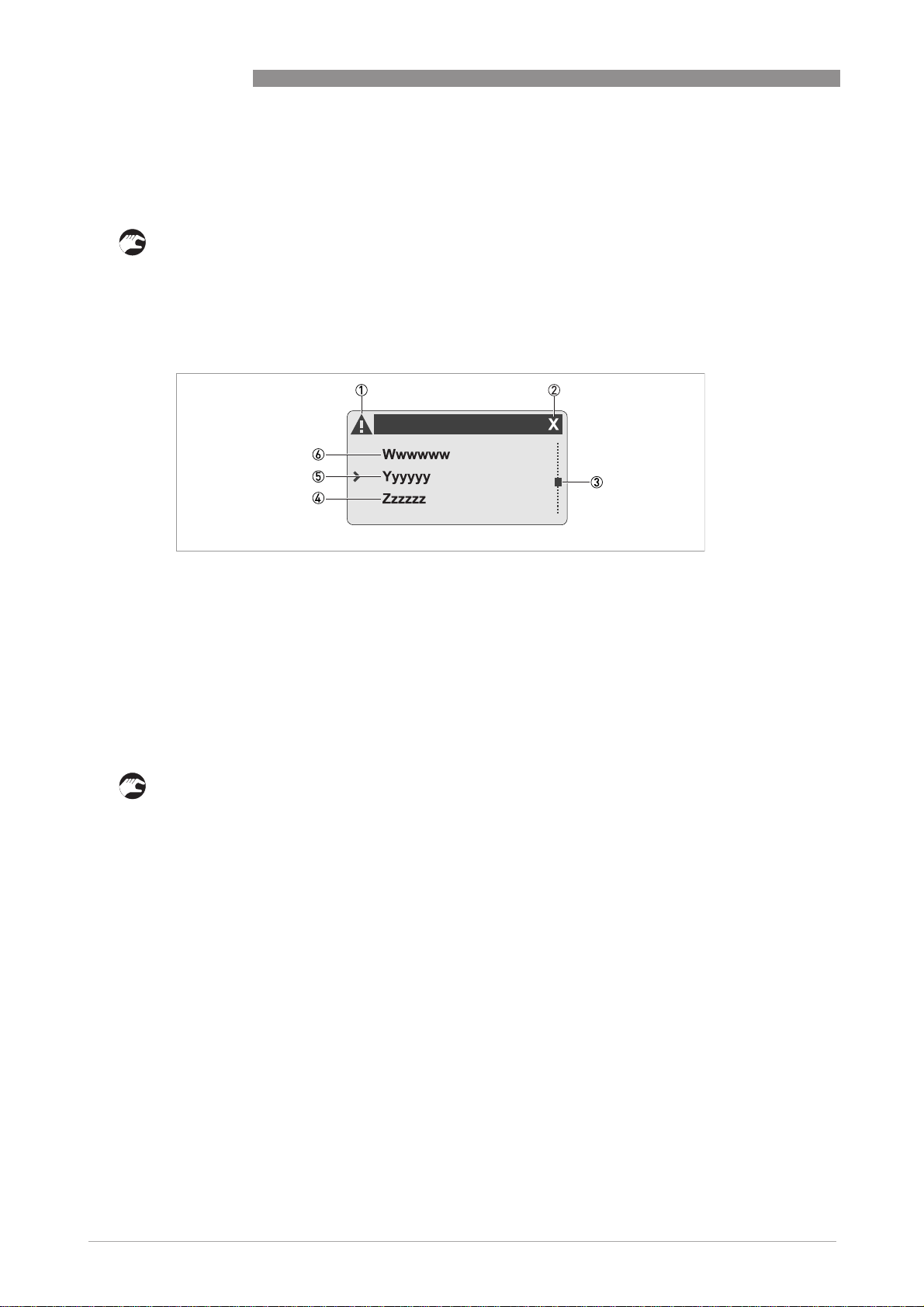
i You are in the main menu level of the menu mode. The display always looks as follows:
Display in main menu level
OPTISENS MAC 100
Figure 6-1:
1 Indicates a possible status message in the status list (only if there are one or more messages)
2 Menu code of selected menu item (see table of menu structure or function tables)
3 Indicates position within the current item list
4 Next menu item, reachable by pressing ↑ (if "- - -" appears in this line, this signalises the end of the list)
5 Selected menu item in bold characters
6 Previous menu item, reachable by pressing ↓ (if "- - -" appears in this line, this signalises the beginning of the list)
The main menu mode consists of the main menus "quick setup", "test", "setup" and "service".
You can either leave the main menu level and return to the measuring mode or choose and enter
a main menu:
• Press ^ to return to the measuring mode (in this case a prompt appears and asks if you want
to save the changed data; choose "Yes" or "No" with the help of ↓ or ↑ and confirm by
pressing ^).
• If you do not want to leave the main menu level, press > to enter the first main menu
("quick setup") or choose another main menu with the help of ↑ or ↓ and enter it by
pressing >.
i You are in the submenu level. The display always looks like the drawing on the following
page.
42
www.krohne.com 04/2011 - MA OPTISENS MAC 100 R01 en
Page 43

OPTISENS MAC 100
Display in submenu level
Figure 6-2:
1 Indicates a possible status message in the status list (only if there are one or more messages)
2 Superior main menu
3 Menu code of selected menu item (see table of menu structure or function tables); up to two figures can appear right
beside the character indicating the main menu (one if you are on the first submenu level and two on the second submenu level)
4 Indicates position within the current item list
5 Previous menu item, reachable by pressing ↓ (if "- - -" appears in this line, this signalises the beginning of the list)
6 Currently setting of the chosen menu item in bold character (here 7)
7 Selected menu item, in bold characters
8 Next menu item, reachable by pressing ↑ (if "- - -" appears in this line, this signalises the end of the list)
OPERATION 6
The submenu level consists of the first and second submenu level. The principle of choosing a
menu item is always the same:
• Press > to enter the first menu item or choose another menu item with the help of ↑ or ↓ and
enter it by pressing >.
i You navigate through the tree structure of the submenu level, finally you always reach the
parameter or data level.
• If you want to return to the main menu level without saving the input, press > and ↑ at the
same time.
• If you want to return to the main menu level and save your input, press ^ one or more times
depending on the level you are (pressing ^ results in moving one level upwards until you
reach the main menu level).
INFORMATION!
Like the lowest menu level (i.e. the parameter or data level) some submenus also offer the
possibility to make adjustments. The procedure is similar to the procedure on the parameter
level, see next page.
www.krohne.com04/2011 - MA OPTISENS MAC 100 R01 en
43
Page 44

6 OPERATION
On the parameter level you see a list with one or more parameters or data. You can scroll
through this list using ↑ or ↓:
INFORMATION!
In this list all parameters or data which have been changed (i.e. they deviate from the default
setting) have a hook at the right end of their line(see position number 4 in the following
drawing).
Display with list of parameters or data
Figure 6-3:
1 Indicates a possible status message in the status list (only if there are one or more messages)
2 Superior submenu or subsequent submenu
3 Menu code of selected parameter (see table of menu structure or function tables)
4 Denotes the change of a parameter (this marking allows to simply and quickly identify all data which differ from the
default setting when browsing through the list)
5 Instead of the check mark there can also appear a lock symbol at this position; it indicates a parameter that cannot be
changed, because of the parameter lock on the front.
6 Indicates position within the current item list
7 Previous menu item, reachable by pressing ↓ (if "- - -" appears in this line, this signalises the beginning of the list)
8 Currently setting of the chosen menu item, also in bold character (here 7)
9 Selected menu item, in bold characters
10 Next menu item, reachable by pressing ↑ (if "- - -" appears in this line, this signalises the end of the list)
OPTISENS MAC 100
44
www.krohne.com 04/2011 - MA OPTISENS MAC 100 R01 en
Page 45

OPTISENS MAC 100
On the parameter or data level you have the possibility to change the decimal point, numbers,
units or settings. Before that you have to choose the desired parameter or data and open to edit
it:
• Press > to open and edit the first list item or choose another item with the help of ↑ or ↓ and
press >.
i You are in the parameter edit mode now. All changeable values are highlighted and shown
reverse (if nothing is shown reverse, you are in the read-only view and you cannot change
the setting).
• Use ↑ or ↓ to change the highlighted area; if there are numerical values or a decimal point to
be changed, you can move the cursor with > to the desired position and change its value with
the help of ↑ or ↓.
• If you want to return to the parameter or data list and save your input, press ^; afterward you
can press ^ one or more times to return to the main menu.
• If you want to return to the next higher level without saving the input, press > and ↑ to the
same time.
Display with parameter or data ready to edit
OPERATION 6
Figure 6-4:
1 Indicates a possible status message in the status list (only if there are one or more messages)
2 Superior submenu or subsequent submenu
3 Menu code of selected parameter (see table of menu structure or function tables)
4 Symbol denotes that there is a factory setting
5 Symbol denotes that there is a permissible value range
6 Permissible value range (for numerical values)
7 Currently set value, unit or function that you can change (always appears with highlighted background)
8 Current selected parameter
9 Factory setting of parameter (non-alterable)
www.krohne.com04/2011 - MA OPTISENS MAC 100 R01 en
45
Page 46

6 OPERATION
Some parameters allow to select and move the decimal point. If you do so and the point reaches
the right (left) end of the related number, further pressing the key ↑ (↓) changes the format to
exponential. In the following example the exponential syntax means 54000 x 10
suppressed to save space. The exponent is increased (decreased) by a factor of three every time
you press the key ↑ (↓). The change of the exponent to zero resets the exponential syntax to the
normal presentation.
Decimal point and exponential format in the parameter edit mode
OPTISENS MAC 100
3
, where the 10 is
6.3.2 Menu "quick setup"
The menu structure consists of four main menus. The first one is the main menu "quick setup",
which groups the most important functions of the other main menus. In this way you have the
possibility to configure the signal converter quickly.
46
www.krohne.com 04/2011 - MA OPTISENS MAC 100 R01 en
Page 47

OPTISENS MAC 100
6.4 Menu mode structure
INFORMATION!
The following table just presents an overview. When programming the device, always consult the
function tables additionally as they contain further information!
OPERATION 6
Measuring
mode
3 or 4
pages,
scrolling
with ↓ or ↑
Main menu Submenu Parameter
>2.5s^A quick setup
>2.5s^B test
A quick setup >^A1 language >^For further
A quick setupA quick setup
A2 Tag
A3 manual hold
A4 set clock
A5 reset errors
A6 analog
outputs
A9...A11: calibration menus for process input A;
existence of the single sub-menus depends on the
hardware setting and the used sensor (e.g. if you use a
pH sensor then only the menu A8 with the name "pH
cal." appears); refer to sensor manual for further
information.
A12...A16: calibration sub-menus for process input B,
existence also depending on the hardware setting and
the used sensor.
↓↑ ↓↑ ↓↑ ↓↑
B test >^B1 Simulation
B testB test
↓↑ ↓↑ ↓↑ ↓↑
Process Input A>^
B2 Simulation
Process Input B
>^A6.1 measurement
A6.2 unit
A6.3 range
A6.4 time constant
B1.1...B1.7: simulation menus
for process input A; existence of
the single sub-menus depends
on the hardware setting and the
used sensor, refer to sensor
manual for further information.
B2.1...B2.7: simulation menus
for process input B; existence of
the single sub-menus depends
on the hardware setting and the
used sensor, refer to sensor
manual for further information.
information
see function
tables.
>^For further
information
see function
tables.
www.krohne.com04/2011 - MA OPTISENS MAC 100 R01 en
47
Page 48

6 OPERATION
OPTISENS MAC 100
Measuring
mode
3 or 4
pages,
scrolling
with ↓ or ↑
Main menu Submenu Parameter
>2.5s^B test
>2.5s^C setup
B test >^B3 simulation IO >^B3.1 - / current output A >^For further
B testB test
B3.2 - / current output B
B3.3 - / current output C
B3.4 - / control input D
B3.5 - / status output R1 or limit
switch R1
B3.6 - / status output R2 or limit
switch R2
B3.7 - / status output R3 or limit
switch R3
B4 actual values B4.1...B4.8: menus which show
B5 logbooks B5.1 status log
B6 information B6.1 C number
↓↑ ↓↑ ↓↑ ↓↑
C setup >^C1 process input A>^C1.1...C1.18: menus for the
C setupC setup
C2 process input
B
↓↑ ↓↑ ↓↑ ↓↑
the corresponding actual
reading; existence of the single
sub-menus depends on the
hardware setting and the used
sensor; refer to sensor manual
for further information.
B5.2 calibration log
B6.2 process input A
B6.3 process input B
B6.4 SW.REV. MS
B6.5 SW.REV. UIS
B6 Electronic Revision ER
setup of the corresponding
process input; existence of the
single sub-menus depends on
the hardware setting and the
used sensor; refer to sensor
manual for further information.
C2.1...C2.17: menus for the
setup of the corresponding
process input; existence of the
single sub-menus depends on
the hardware setting and the
used sensor; refer to sensor
manual for further information.
information
see function
tables.
>
^
48
www.krohne.com 04/2011 - MA OPTISENS MAC 100 R01 en
Page 49

OPTISENS MAC 100
OPERATION 6
Measuring
mode
3 or 4
pages,
scrolling
with ↓ or ↑
Main menu Submenu Parameter
>2.5s^C setup
D service:
D service: This menu is password protected and contains functions to be used by service personnel only.
D service:D service:
C setup >^C3 I/O >^C3.1 hardware >^For further
C setupC setup
C3.2 current output A
C3.3 current output B
C3.4 current output C
C3.5 control input D
C3.6 status output R1 or limit
switch R1
C3.7 status output R2 or limit
switch R2
C3.8 status output R3 or limit
switch R3
C4 I/O HART (in preparation)
C5 device >^C5.1 device info
C5.2 display
C5.3 1.meas.page
C5.4 2.meas.page
C5.5 graphic page
C5.6 special functions
C5.7 units
↓↑ ↓↑ ↓↑ ↓↑
information
see function
tables.
www.krohne.com04/2011 - MA OPTISENS MAC 100 R01 en
49
Page 50

6 OPERATION
OPTISENS MAC 100
6.5 Function tables
6.5.1 Menu A, quick setup
INFORMATION!
Note that the appearance of some sub-menus depends on the hardware setting and the used
sensor(s). E.g. if you use a pH sensor then only the menu A8 with the name "process input A
pH calibration" appears.
A1, language
Language selection (depends on the region for which the converter has been ordered). Available languages: German,
English.
A2, tag
Measuring point identifier (Tag no.), helps to identify the device in a plant, appears in the LC display header in the
normal measuring mode (up to 8 digits).
A3, manual hold
Manual shift into the simulation mode for maintenance; device aborts measuring and holds all analog measurements
from the process inputs. Options: On (enter the simulation mode) / Off (enter the normal measuring mode again.)
A4, set clock
Manual setting of date and time.
A5, reset errors
This functions allows to reset all errors that are not reset automatically (e.g. power fail or counter overflow). You can
answer the question "reset?" with the following options: no (exit without reset) / yes (reset and exit the function).
50
www.krohne.com 04/2011 - MA OPTISENS MAC 100 R01 en
Page 51

OPTISENS MAC 100
OPERATION 6
A6, analog outputs
Level Designation / function Settings / descriptions
Depending on the hardware setting this menu is applicable to the current outputs A/B/C, the limit switches R1/R2/R3
and the first line of the first measuring page.
A6.1
A6.1 measurement Value used for driving the current output C. You can answer the question
A6.1A6.1
A6.2
A6.2 unit Unit for the current output range, the class of the unit depends on the
A6.2A6.2
A6.3
A6.3 range Range of the main current output C of the device. You can answer the
A6.3A6.3
"use all outputs?" with the following options: no (exits the function using the
value only of current output C) / yes (exits the function copying the value to
all analog outputs).
measurement used at this current output (for further information refer to
function C5.7 "Units").
question "use at all output?" with the following options: no (exits the function
using the value only of current output C) / yes (exits the function copying the
value to all analog outputs).
A6.4
A6.4 time constant Time constant of the current output C
A6.4A6.4
A7...A16
The existence of the single menus depends on the hardware setting and the used sensor; refer to sensor manual for
further information.
www.krohne.com04/2011 - MA OPTISENS MAC 100 R01 en
51
Page 52

6 OPERATION
OPTISENS MAC 100
6.5.2 Menu B, test
INFORMATION!
Note that the appearance of some sub-menus depends on the hardware setting and the used
sensor(s). E.g. if you use a single pH sensor then only the sub-menu B1 "Simulation Process
Input A" appears and B2 "Simulation Process Input B" does not appear. Within the sub-menu B1
you would find the sub-menu B1.7 "pH".
B1, Simulation Process Input A
This menu groups several functions to simulate the measuring values of the corresponding process input; the existence
of the single sub-menus depends on the hardware setting and the used sensor, refer to sensor manual for further
information. The procedure to start the simulation process is the same for all functions, refer to
measured values
on page 60.
B2, Simulation IO
This menu groups several functions to simulate the measuring values of the corresponding process input; the existence
of the single sub-menus depends on the hardware setting and the used sensor, refer to sensor manual for further
information. The procedure to start the simulation process is the same for all functions, refer to
measured values
on page 60.
Simulation of
Simulation of
B3, Simulation IO
Level Designation / function Settings / descriptions
This menu groups several functions to simulate the input and output values. The procedure to start the simulation
process is the same for all function, refer to
B3.1
B3.1 - / current output A Allows simulation of the corresponding output value.
B3.1B3.1
B3.2
B3.2 - / current output B
B3.2B3.2
B3.3
B3.3 - / current output C
B3.3B3.3
B3.4
B3.4 - / control input D Allows simulation of the input value.
B3.4B3.4
B3.5
B3.5 - / status output R1 or
B3.5B3.5
B3.6
B3.6 - / status output R2 or
B3.6B3.6
B3.7
B3.7 - / status output R3 or
B3.7B3.7
limit switch R1
limit switch R2
limit switch R3
Simulation of measured values
Allows simulation of the corresponding frequency output, status output or
limit switch.
on page 60.
B4, actual values
This menu groups several functions which allow to display the corresponding actual reading; the existence of the single
sub-menus depends on the hardware setting and the used sensor, refer to sensor manual for further information.
52
www.krohne.com 04/2011 - MA OPTISENS MAC 100 R01 en
Page 53

OPTISENS MAC 100
OPERATION 6
B5, logbooks
Level Designation / function Settings / descriptions
B5.1
B5.1 status log Contains the latest changes of the device status,for further information refer
B5.1B5.1
B5.2
B5.2 calibration log Contains the results of the latest calibrations,for further information refer to
B5.2B5.2
to refer to
refer to
Status log and calibration log
Status log and calibration log
on page 61.
on page 61.
B6, information
Level Designation / function Settings / descriptions
This menu groups several other menus which contain device specific information. The build-up of the display is the
same for all menus:
• 1st line: ID No. of the circuit board
• 2nd line: software version
• 3rd line: production date
B6.1
B6.1 C number Identifies the type of electronics, is also located on the converter nameplate.
B6.1B6.1
B6.2
B6.2 process input A Gives information about the electronical part of process input A.
B6.2B6.2
B6.3
B6.3 process input B Gives information about the electronical part of process input B.
B6.3B6.3
B6.4
B6.4 SW.REV.MS Gives information about the main software of the electronics.
B6.4B6.4
B6.5
B6.5 SW.REV.UIS Gives information about the user interface of the device.
B6.5B6.5
B6.7
B6.7 Electronic Revision ER Reference identification number, electronic revision and production date of
B6.7B6.7
the device; includes all hardware and software changes
www.krohne.com04/2011 - MA OPTISENS MAC 100 R01 en
53
Page 54

6 OPERATION
OPTISENS MAC 100
6.5.3 Menu C, setup
INFORMATION!
The converter has two process inputs, input A and input B. Each process input has an own
submenu in this main menu. Process input A is always present, i.e. there is always a board in the
interface "Pos. A" in the connection area. The interface of process input B only has a board with
the two channel converter. Be aware that the definition which kind of measurement a process
input can do is defined when ordering the device. The configuration cannot be changed later.
INFORMATION!
Note that the appearance of some sub-menus depends on the hardware setting and the used
sensor(s).
C1, process input A
The structure of this menu within your device depends on the hardware setting and the kind of sensor connected to the
process input. Refer to the sensor manual for further information!
C2, process input B
The structure of this menu within your device depends on the hardware setting and the kind of sensor connected to the
process input. Refer to the sensor manual for further information!
C3, I/O (Inputs/outputs)
Level Designation / function Settings / descriptions
This menu groups all I/O functions together.
C3.1
C3.1 hardware This sub-menu allows to select different settings of the output terminals.
C3.1C3.1
C3.1.1 terminals A Setting for current output A, B or C. Options: current output (current output
C3.1.2 terminals B
C3.1.3 terminals C
C3.1.4 terminals D Setting for control input.
C3.1.5 terminals R1 Setting for status output or limit switch (R1, R2 or R3, if existent). Options:
C3.1.6 terminals R2
C3.1.7 terminals R3
The menus for the different terminals are identical, if they have the same
function (e.g. the menus of all status outputs are identical). Note that a
change of the configuration is completely available after restart of the device
(leave the menu accepting the changes)! The menu structure of the changed
output will be immediately available after the change. Parameters can be set
immediately as well, but simulations and test functions will be functional
after restart.
active) / off (no function at terminals).
Options: control input (control input active) / off (no function at terminals).
• status output: status output active
• limit switch: limit switch active
• off: no function at terminals
C3.2
C3.2 current output A Fine adjustment of the corresponding current output.
C3.2C3.2
C3.2.1 range 0%…100% Current range for the selected measurement (0…100%).
Range: 0.00...20 mA (condition: 0 mA ≤ 1st value ≤ 2nd value ≤ 21.5 mA)
C3.2.2 extended range Defines the min. and max. limits (the limits defined in the previous function
54
are exceeded linearly up to these values).
Range: 3.5...21.5 mA (condition: 3.5 mA ≤ 1st value ≤ 2nd value ≤ 22 mA)
www.krohne.com 04/2011 - MA OPTISENS MAC 100 R01 en
Page 55

OPTISENS MAC 100
Level Designation / function Settings / descriptions
OPERATION 6
C3.2.3 error current This function allows to define the current which indicates the error
C3.2.4 error condition This function allows to define which error categories will be indicated (for
C3.2.5 measurement This function allows to define the value which activates the output. The
C3.2.6 range Range for the measurement (0…100%) which has been set in the previous
C3.2.7 limitation Limitation before applying the time constant.
C3.2.8 time constant Range: 000.1…100 seconds
C3.2.9 information Contains serial number, software version number and production date of the
C3.2.10 simulation This function allows to simulate the output values for the corresponding
condition, for further information refer to
page 62.
Range: 3...22 mA (condition: outside of extended range)
further information refer to
page 66). Options:
Status messages and diagnostic information
• error in device: only errors of category F
• application error: errors of categories F
• out of specification: errors of categories F
available options depend on the hardware setting and the kind of the sensor
used, refer to the sensor manual for further information.
function: 0...xx.xx _ _ _ (format and unit depend on the measurement, see
above).
Range: -150…+150%
circuit board.
current output. For further information refer to
refer to
Simulation of measured values
Error current of current output
F
FF
F and F
FF
F, F and S
FF
on page 60.
Menu B, test
on page 52and
on
on
C3.3
C3.3 current output B Refer to submenus of current output A (all submenus and options are
C3.3C3.3
C3.4
C3.4 current output C Refer to submenus of current output A (all submenus and options are
C3.4C3.4
C3.5
C3.5 control input Fine adjustment of the control input.
C3.5C3.5
C3.5.1 mode This function allows to define the function of the control input. Note that the
identical, except that they start with C3.3).
identical, except that they start with C3.4).
actual selection list may be reduced according to the available functions.
Control input A and control input B have the same possible selections. When
there is a function of both control inputs to the same parts of the device, the
function set at control input A is dominant. If for instance control input B has
the setting "stop all counters" and control input A has the setting "reset
counter 1", then control input B will not have an effect on counter 1. Options:
• off: control input is disabled.
• hold all outputs: all outputs are fixed to the current value; a message of the
category "C" is generated when active, this does not include display and
counters.
• all outputs to zero: all outputs excluding display and counters are set to
0%.
• flow control: process inputs monitor control input; error level is set to "out
of specification" if control input is set, note that ASR is disabled in this
case!
C3.5.2 invert signal This function allows to define how the control input is activated.
Options: off (control input is activated when a current is applied at the input,
i.e. by voltage to passive inputs or low resistor to active input) / on (control
input is activated when no current is applied at the input, i.e. low voltage to
passive inputs or high resistor to active inputs).
www.krohne.com04/2011 - MA OPTISENS MAC 100 R01 en
55
Page 56

6 OPERATION
Level Designation / function Settings / descriptions
OPTISENS MAC 100
C3.5.3 information Contains serial number, software version number and production date of the
C3.5.4 simulation This function allows to simulate input values for the control input. For
C3.6
C3.6 status output R1 or limit
C3.6C3.6
C3.6.1 "mode" (status output) or
switch R1
"measurement" (limit
switch)
circuit board.
further information refer to
of measured values
Fine adjustment of the corresponding status output or limit switch; the
function of the following sub-menus depend on the hardware setting.
Status output: this function allows to select the mode; note that the following
option list can be reduced depending on the available functions; for further
information about the messages refer to
information
on page 66). Options:
on page 60.
• application error: output is activated if the errors "F
application error" emerge
• out of specification: output is activated if the errors "F
"F application error" emerge, it is also activated if a warning of the
category "out of specification" is present
Menu B, test
on page 52and refer to
Simulation
Status messages and diagnostic
F error in device" or "F
FF
F error in device" or
FF
• control input: signal from control input is forwarded to the status output
• off: status output deactivated
• error in device: output is activated if the error "F
Limit switch: this function allows to define the value which activates the limit
switch. The available options depend on the hardware setting and the kind of
the sensor used, refer to the sensor manual for further information.
C3.6.2 "invert signal" (status
output) or "threshold"
(limit switch)
C3.6.3 "information" (status
output) or "time constant"
(limit switch)
C3.6.4 "simulation" (status
output) or "invert signal"
(limit switch)
C3.6.5 information Only available for limit switch; contains serial number, software version
C3.6.6 simulation This function allows to simulate the status for the corresponding limit
Status output: this function allows to define how the status output is
activated. Options: off (activated status output generates a high current) /
on (activated output generates a low current).
Limit switch: this function allows to define the switching level. The first
value defines the level, the second level defines a hysteresis.
Status output: contains serial number, software version number and
production date of the circuit board.
Limit switch: filter for limit switch.
This function allows to simulate the status of the corresponding status input.
For further information refer to
Simulation of measured values
Limit switch: this function allows to define how the limit switch is activated.
Options: off (exceeded limit generates a high current at the output) /
on (exceeded limit generates a low current at the output).
number and production date of the circuit board.
switch. For further information refer to
Simulation of measured values
Menu B, test
on page 60.
Menu B, test
on page 60.
F error in device" emerges
FF
on page 52and refer to
on page 52and refer to
C3.7
C3.7 status output R2 or limit
C3.7C3.7
C3.8
C3.8 status output R2 or limit
C3.8C3.8
56
switch R2
switch R2
Refer to submenus of status output or limit switch R1 (all submenus and
options are identical, except that they start with C3.7).
Refer to submenus of status output or limit switch R1 (all submenus and
options are identical, except that they start with C3.8).
www.krohne.com 04/2011 - MA OPTISENS MAC 100 R01 en
Page 57

OPTISENS MAC 100
OPERATION 6
C5, device
Level Designation / function Settings / descriptions
This menu groups all functions that have no effect on the measurement or any output directly.
C5.1
C5.1 device info Information about the device.
C5.1C5.1
C5.1.1 tag Refer to A2 "tag".
C5.1.2 C number Refer to B6.1 "C number".
C5.1.3 device serial no. Serial number of the system
C5.1.4 electronic serial no. Serial number of the electronics assembly
C5.1.5 SW.REV.MS Refer to B6.4 "SW.REV.MS".
C5.1.6 Electronic Revision ER Refer to B6.6 "Electronic Revision ER".
C5.2
C5.2 display Groups several function for the fine adjustment of the display.
C5.2C5.2
C5.2.1 language Refer to A1 "language".
C5.2.2 contrast This function allows to adjust the contrast of the display (e.g. at extreme
C5.2.3 default display This function allows to set the default page in the normal measuring mode;
temperatures). Note that a change of the contrast takes place immediately,
not just when the menu mode is excited! You cannot reset a change when
leaving the programming mode without saving the changes!
Range: -9…0…+9
after a short delay period the display always returns to this page
automatically. Options:
• none: no default measuring page, i.e. the display always stays on the
currently selected page.
• 1. meas. page: set this page as default.
• 2. meas. page: set this page as default.
• status page: show only status messages as default page.
• graphic page: show only trend display of the first measuring result as
default page.
C5.2.5 information Contains serial number, user interface software version number and
C5.3
C5.3 1. meas. page This menu groups all settings for the first measuring page. The menus are
C5.3C5.3
C5.3.1 function This function allows to specify the number of lines which display the
production date of the circuit board.
equal for the first and second measuring page.
measured value(s). Options:
• two lines: display shows two lines of measuring results on this page.
• three lines: display shows two three of measuring results on this page.
• one line: display shows one line of measuring results on this page.
C5.3.2 measurement 1.line This function allows to define which measured value appears in the first line
C5.3.3 range Range for the measurement (0…100%) which has been set in the previous
C5.3.4 limitation Limitation before applying the time constant.
C5.3.5 time constant Range: 000.1…100 seconds
of the display. The available options depend on the hardware setting and the
kind of the sensor used, refer to the sensor manual for further information.
function: 0...xx.xx _ _ _ (format and unit depend on the measurement, see
above).
Range: -150…+150%
www.krohne.com04/2011 - MA OPTISENS MAC 100 R01 en
57
Page 58

6 OPERATION
Level Designation / function Settings / descriptions
OPTISENS MAC 100
C5.3.6 format 1.line This function allows to define the number of digits after the decimal point
C5.3.7 measurement 2.line This function allows to define which measured value appears in the second
C5.3.8 format 2.line This function allows to define the number of digits after the decimal point
C5.3.9 measurement 3.line This function allows to define which measured value appears in the third line
C5.3.10 format 3.line This function allows to define the number of digits after the decimal point
C5.4
C5.4 2. meas. page Refer to sub-menus of C5.3 "1. meas. page" (all submenus and options are
C5.4C5.4
C5.5
C5.5 graphic page The graphic page always shows the trend curve of the first measured value
C5.5C5.5
C5.5.1 select range This functions allows to define the scaling of the Y-axis.
C5.5.2 range If the option "manual" is selected in the previous function, you can define the
C5.5.3 time scale This function allows to define the scaling of the X-axis (i.e. total time span of
(i.e. the decimal places).
Options: automatic (adaptation carried out automatically according to the
available space) / X (= none) …X.XXXXXXXX (max. 8 digits).
line of the display. The existence and structure of this menu within your
device depends on the hardware setting and the kind of sensor connected to
the process input. Refer to the sensor manual for further information!
(i.e. the decimal places). The existence of this menu depends on the
hardware setting, the options comply with the options for the format of the
first line of the display (see C5.3.7).
of the display. The existence and structure of this menu within your device
depends on the hardware setting and the kind of sensor connected to the
process input. Refer to the sensor manual for further information!
(i.e. the decimal places). The existence of this menu depends on the
hardware setting, the options comply with the options for the format of the
first line of the display (see C5.3.7).
identical, except that they start with C5.4 or C5.4.X).
of the first measuring page (see menu C5.3.2). With the help of the functions
in this submenu you can scale the X-axis (time) and the Y-axis.
Options: manual (set range in the following function C5.5.2) /
automatic (automatic depiction based on the measured values; the range
will be reset after a parameter change or a new start-up of the device only).
scaling of the Y-axis manually with the help of this function.
the trend).
C5.6
C5.6 special functions This menu groups several special functions.
C5.6C5.6
C5.6.1 reset errors Refer to A5 "reset".
C5.6.2 save settings This function allows to save all settings and choose a storage place. For
C5.6.3 load settings This function allows to load saved settings from different storage places. For
C5.6.4 password quick set This function allows to define and activate a password for the access to the
C5.6.5 password setup This function allows to define and activate a password for the access to the
58
further information refer to
further information refer to
quick setup menu.
Options: XXXX (if you enter four digits in the range of 0001...9999, then the
password protection is enabled) / 0000 (password protection disabled).
setup menu.
Options: XXXX (if you enter four digits in the range of 0001...9999, then the
password protection is enabled) / 0000 (password protection disabled).
www.krohne.com 04/2011 - MA OPTISENS MAC 100 R01 en
Save settings
Load settings
on page 65.
on page 65.
Page 59

OPTISENS MAC 100
OPERATION 6
Level Designation / function Settings / descriptions
C5.7
C5.7 units This menu groups several functions to define the units of the measuring
C5.7C5.7
C5.7.1 concentration absolute This function allows to define the absolute concentration unit used for
C5.7.2 Text free unit This function allows to define a text if a free unit was chosen for the absolute
C5.7.3 [g/l]*factor This function allows to define the conversion factor if a free unit was chosen
C5.7.4 rel. concentration DO This function allows to define the relative concentration unit used for the
C5.7.5 conc.solution This function allows to define the concentration unit used for solution
C5.7.6 spec.conductivity This function allows to define the specific conductivity unit.
C5.7.7 Text free unit Properties comply with C5.7.2.
C5.7.8 [S/m]*factor Properties comply with C5.7.3 except that the measurement value is [S/m].
C5.7.9 spec.resistance This function allows to define the specific resistance unit.
C5.7.10 Text free unit Properties comply with C5.7.2.
C5.7.11 [Ohm x m]*factor Properties comply with C5.7.3 except that the measurement value is
C5.7.12 temperature This function allows to define the temperature unit.
C5.7.13 air pressure This function allows to define the air pressure unit.
C5.7.14 probe current This function allows to define the probe current unit.
C5.7.15 Text free unit Properties comply with C5.7.2.
C5.7.16 [A]*factor Properties comply with C5.7.3 except that the measurement value is [A].
results. These unit are used for all values of the related unit group on the
display (measuring screen and parameters).
amperometric measurements.
Options: mg/l, µg/l, ppm (parts per million), ppb (parts per billion), free unit.
concentration (see previous function C5.7.1).
Conditions: at most three characters before and three after the slash!
for the absolute concentration (see previous function C5.7.1). With this factor
the measurement value in g/l is multiplied to get a value in the free unit.
measurement of DO (dissolved oxygen).
Options: %, ppm (parts per million), ppb (parts per billion).
measurement.
Options: %, ppm (parts per million), ppb (parts per billion).
Options: mS/cm, µS/cm, free unit.
Options: MOhm x cm, free unit.
[Ohm/m].
Options: °C, °F, K.
Options: Pa, kPa, bar, mbar, Torr, atm.
Options: mA, free unit.
6.5.4 Menu D, service
This menu is password protected and contains functions to be used by service personnel only.
www.krohne.com04/2011 - MA OPTISENS MAC 100 R01 en
59
Page 60

6 OPERATION
6.6 Functions in detail
6.6.1 Manual hold
To avoid alarms on the distributed control system (DLC) when temporary removing the sensor
(i.e. for maintenance), the converter has a hold function (A3 "manual hold"). This function
"freezes" all outputs (i.e. the display and the current outputs) on the last measured value.
INFORMATION!
As an indication that the manual hold function is active, the "warning sign" in the upper left
corner of the display appears. Meanwhile the status messages show "checks in progress".
OPTISENS MAC 100
For further information about the status messages refer to
information
on page 66.
6.6.2 Simulation of measured values
The device offers the possibility to simulate the measured values of the process inputs as well as
the values for the control input and the output values (functions B1...B3, C3.2.10, C3.5.4, C3.6.4,
C3.6.6). Depending on the hardware setting and the used sensor(s) the main menu B "TEST"
contains up to three sub-menus. Also depending on the hardware setting and the used sensor(s)
these submenus contain functions which can initiate the simulation process. The procedure is
the same for all functions:
• Choose the function with the help of ↓ or ↑ and press ^.
i You see the two options "set value" (opens the editor to enter the simulation value) and
"break" (exits the menu without simulation).
• Choose the desired option with the help of ↑ or ↓ and press ^.
i If you chose "set value", the device asks "start simulation" and offers the options "no" (exits
the menu without simulation) or "yes" (starts the simulation finally).
• Choose the desired option with the help of ↑ or ↓ and press ^.
i If you chose "yes", the simulation starts.
Status messages and diagnostic
60
www.krohne.com 04/2011 - MA OPTISENS MAC 100 R01 en
Page 61

OPTISENS MAC 100
6.6.3 Status log and calibration log
The calibration log (B5.1) contains the results of the latest calibrations. Also within this log you
can move up or down with the help of ↑ or ↓ and you can exit it with ^.
Figure 6-5: Example for calibration log
The status log (B5.2) contains the latest changes of the device status. Within the log you can
move up or down with the help of ↑ or ↓, you can exit the log with ^. There are two type of status
messages:
OPERATION 6
• Checked boxes: they have a hook in a square to the right of them and stand for emerging
events (e.g. current loop open).
• Unchecked boxes: they have a square without a hook to the right of them and stand for
leaving events (e.g. if an application error is not longer available).
Figure 6-6: Example for status log
www.krohne.com04/2011 - MA OPTISENS MAC 100 R01 en
61
Page 62

6 OPERATION
6.6.4 Error current of current output
The function C3.2.3 "error current" allows to define the current which indicates the error
condition:
Current output in mA
1 Extended range
2 Nominal range
3 Range of lower error current
4 Range of upper error current
NAMUR current output in mA
OPTISENS MAC 100
1 Extended range
2 Nominal range
3 Range of lower error current
4 Range of upper error current
62
www.krohne.com 04/2011 - MA OPTISENS MAC 100 R01 en
Page 63

OPTISENS MAC 100
6.6.5 Overflow sign and exponential format
If there is not enough space available for the complete measured value, the display either shows
the overflow sign or uses the exponential format (depending on the settings in functions ).
Overflow sign
The user can define that a particular display line should consist of a fixed number of digits. For
this purpose the corresponding function C5.3.7, C5.3.9 or C5.3.11 must not have the setting
"automatic". If the measuring result in this line exceeds this number, the display shows the
overflow sign right beside the plus/minus sign. It appears as a triangle pointing to the left as
shown in the following drawings:
Overflow, one line
OPERATION 6
Overflow, two lines
Overflow, three lines
www.krohne.com04/2011 - MA OPTISENS MAC 100 R01 en
63
Page 64

6 OPERATION
Exponential format
If the format of the related display line is set to "automatic" (function C5.3.7, C5.3.9 or C5.3.11),
long measuring results appear in an exponential format:
Exponential format, one line
Exponential format, two lines
OPTISENS MAC 100
Exponential format, three lines
64
www.krohne.com 04/2011 - MA OPTISENS MAC 100 R01 en
Page 65

OPTISENS MAC 100
6.6.6 Save settings
The device offers the possibility to save all settings in different storage places:
• Go into the menu mode and call up the menu C5.6.2 "save settings".
• Enter the menu with >.
i You see three options: "break" (exits the menu without saving), "backup 1" (saves the
settings in the backup 1 storage place)", "backup 2" (saves the settings in the backup 2
storage place).
• Choose the desired option with the help of ↑ or ↓ and press ^.
i If you chose "backup 1" or "backup 2", the device asks "go on with copy?" and offers two
options: "no" (exit without saving) and "yes" (copy the actual settings to the selected
storage place; note that there is no possibility to undo this command!)
• Choose the desired option with the help of ↑ or ↓ and press ^.
i The device has successfully saved the settings in the chosen storage place.
6.6.7 Load settings
The device offers the possibility to load settings from different storage places where they have
been saved before:
OPERATION 6
• Go into the menu mode and call up the menu C5.6.3 "load settings".
• Enter the menu with >.
i You see four options: "break" (exits the menu without saving), "factory settings" (loads the
settings from the delivery), "backup 1" (loads the settings from the backup 1 storage place)
and "backup 2" (loads the settings from the backup 2 storage place).
• Choose the desired option with the help of ↑ or ↓ and press ^.
i If you chose one of the options except "break", the device asks "go on with copy?" and offers
two options: "no" (exit without saving) and "yes" (copy the selected settings from their
storage place; note that there is no possibility to undo this command!)
• Choose the desired option with the help of ↑ or ↓ and press ^.
i The device has successfully loaded the settings from the chosen storage place.
www.krohne.com04/2011 - MA OPTISENS MAC 100 R01 en
65
Page 66

6 OPERATION
6.6.8 Passwords
You can activate passwords for different menu levels (function C5.6.4 and C5.6.5):
Password levels
Menu Required password Point of query Preview of setting
OPTISENS MAC 100
possible
Quick setup For quick setup At entry to the
Test For setup
Setup For setup
Service For service At entry to the service
parameter edit mode
menu
Common usage
• Protection of the menus "Test" and "Setup" with a password, free access to the menu "Quick
setup". You can achieve this by activating a setup password only.
• Protection of the quick setup with a known password and confidential setup password to
protect the quick setup against arbitrary use and the setup and test menus against misuse.
This is done by activating a password for the menus "setup" and "quick setup".
INFORMATION!
If you activate a password for the menu "Quick setup" only and not for the menu "Setup", the
menus "Setup" and "Test" will also be protected by the quick setup password.
6.7 Status messages and diagnostic information
INFORMATION!
Note the following information concerning the tables with the status messages in the following
subsections:
Yes
No
•
The tables also contain messages related to HART, Profibus, Foundation Fieldbus and
RS485/Modbus devices; though this device features are currently not available but in
preparation.
•
The devices groups all error messages and maps them according to their category and
importance; the following subsections and their tables represent the categories and the
order of importance. You find a short description of the error category in the table below this
admonition.
•
On the display you recognize the error category with the help of the character in front of the
message (e.g. all failure messages start with a bold "FFFF"); these characters are independent of
the used language, they were individually defined by the manufacturer.
•
If messages of the category FFFF, F and S appear and the device is in the normal measuring
mode, a triangle in the header appears (this triangle does not appear if only information is
shown).
66
www.krohne.com 04/2011 - MA OPTISENS MAC 100 R01 en
Page 67

OPTISENS MAC 100
OPERATION 6
INFORMATION!
Note that messages are shown in the GDC device for information purposes, too. They do not
effect any status change of the device or the measured values and are not planned in NE64,
VDI/VDE 2650 or NE107.
Explanation of the error categories
Letter on display Error category according to: Description Action
NE64 VDI/VDE 2650
and NE107
Bold "FFFF" Failure Device failure Whole device or single component(s)
F (not bold) - Application
failure
S - Out of
specification
C Check request Passivated Either the device is outside operation
I - - Information, current measurement is
defective, replacement necessary,
measured values are not valid; mA
output ≤ 3.6 mA or set fault current
(depending on the seriousness of the
fault).
No internal error, but application
error has occurred; device okay, but
measurement not possible.
Measurement out of specification;
measurement continues, but
measured values only restrictedly
usable.
(standby, measured value is fixed or
specified), or the output values are
partially simulated or fixed.
okay and values unrestrictedly valid.
Repair or
replacement
necessary!
Application test
or operator action
necessary!
Maintenance and
an accurate
check required!
Maintenance
required
Depends on error
message, see
table in relevant
section.
www.krohne.com04/2011 - MA OPTISENS MAC 100 R01 en
67
Page 68

6 OPERATION
6.7.1 Error category "Device failure" (bold "F")
INFORMATION!
Regard that in case of an error message of the category "FFFF" the measured values are not valid!
Messages on the display Description Actions
OPTISENS MAC 100
FFFF error in device Error or failure (breakdown) of the complete
FFFF IO 1 Error or failure of corresponding IO;
FFFF IO 2
FFFF parameter Error or failure of data manager; parameter
FFFF configuration Invalid configuration: display, software, bus
FFFF display Error or failure of the display; parameter or
FFFF sensor electronic A
(or B)
FFFF sensor global A (or B) Data error in the global data of the
FFFF sensor local A (or B) Data error in the local data of the
FFFF current output A (or B
or C)
FFFF software user interface Fault revealed by CRC check of operation
FFFF hardware settings The set hardware parameters do not match
FFFF hardware detection Existing hardware cannot be identified;
FFFF RAM/ROM error IO1 A RAM or ROM error is detected during the
FFFF RAM/ROM error IO2
device; parameter or hardware error;
measurement not possible.
parameter or hardware error;
measurement not possible.
or hardware error; measurement not
possible.
parameter or main software do not match
existing configuration.
This error message also appears if a
module has been added or removed, but
configuration has not been confirmed.
hardware error; measurement not possible.
Error or failure of the electronics of
sensor A (or B); parameter or hardware
error; measurement not possible.
electronics of sensor A (or B);
measurement with the affected sensor not
possible.
electronics of sensor A (or B);
measurement with the affected sensor not
possible.
Error or failure of the current output of
terminal A (or B or C); parameter or
hardware error; affected current output not
usable.
software.
the identified hardware; a dialogue appears
in the display.
modules are either unknown or defective.
CRC check.
Group message, when one of the following
or some other severe error occurs.
Load settings (see C5.6.3: backup 1, backup
2 or factory settings). If status message still
does not disappear, replace electronic unit.
If device configuration has not been
changed, but message appears though:
replace electronic unit.
Replace electronic unit.
Check sensor and connection; if both are
okay, replace the electronic unit.
Load settings (see C5.6.3: backup 1, backup
2 or factory settings). If status message still
does not disappear, replace electronic unit.
Replace electronic unit.
Check connection of current output; if it is
okay, replace the electronic unit.
Replace electronic unit.
Answer queries in dialogue mode, follow
directions; replace defective electronic unit.
Replace electronic unit.
68
www.krohne.com 04/2011 - MA OPTISENS MAC 100 R01 en
Page 69

OPTISENS MAC 100
6.7.2 Error category "Application error" ( "F", not bold)
INFORMATION!
Regard that also in case of an error message of the category "F" the measured values are not
valid!
Messages on the display Description Actions
OPERATION 6
F application error Application-dependent fault, but device is
temperature A (or B) Temperature sensor A (or B) is not
pH compensation The pH value is not in the range from 8.5...9
polarisation sens. A (or B) Pre-amplifier is over-ranged by DC offsets
Flow control The flow control which is connected to the
F open circuit A (or B or C) Load on current output A (or B or C) too
Over range CO A (or B
or C)
F active settings Error during the CRC check of the active
F factory settings Error during the CRC check of the factory
F backup 1 settings (or
backup 2 settings)
okay.
connected properly or measurement is out
of range.
(required range for a working
compensation).
due to polarisation.
control input transmits that the flow is too
low for an amperometric measurement.
high, effective current too low.
The current or the corresponding measured
value is limited by a filter setting.
settings.
settings.
Error during the CRC check of the backup 1
or 2 settings.
6.7.3 Error category "Out of specification" (S)
Group message, when errors as described
below or other application errors occur.
Check cabling or replace the sensor!
Assure that the measured liquid has a
pH value in the range from 8.5...9.
Check installation of sensor!
Check the sample flow!
Current not correct, mA output cable has
open circuit or load too high. Check cable,
reduce load to less than 550 Ω!
Extend function C3.2.6 ("range") and
function C3.2.7 ("limitation").
Upload backup 1 or backup 2 settings, check
and adjust if necessary.
Save active settings in backup 1 or 2.
INFORMATION!
Regard that in case of an error message of the category "S" the measured values are only
conditionally usable!
Messages on the display Description Actions
S uncertain measurem. Group message, when errors as described
S sensor electronic A
(or B)
S temperature A (or B) Measured temperature values from sensor
S slope A (or B) Slope of the pH electrode A (or B) Replace the electrode
below or other influences occur; measured
values are only conditionally usable.
Measured values from sensor
electronic A (or B) are only conditionally
usable.
electronic A (or B) are only conditionally
usable.
Device maintenance necessary.
Sensor maintenance necessary.
Temperature sensor maintenance
necessary.
www.krohne.com04/2011 - MA OPTISENS MAC 100 R01 en
69
Page 70

6 OPERATION
6.7.4 Error category "Check request" or "Run check" (C)
Messages on the display Description Actions
OPTISENS MAC 100
C checks in progress Test mode of the device. Measured values
C sensor electronic A
(or B)
C manual hold The measurements from the sensor A and B
are possibly simulated values or values with
fixed settings.
Test function of the sensor electronic A
(or B) is activated.
are simulated.
Message depending on the situation via
HART
None
Deactivate manual hold (A3)
6.7.5 Error category "Information" (I)
Messages on the display Description Actions
I control input active Signal "High" on the control input. None
I over range display 1
(or 2)
I backplane sensor The data on the backplane are not usable
I backplane settings The global settings on the backplane are not
I backplane difference The data on the backplane differ from the
I write cycles overfl. The maximum number of write cycles of the
1st line on measuring page 1 (or 2) of
display limited by filter setting.
because they have been generated with an
incompatible version.
usable because they have been generated
with an incompatible version.
data in the display. If the data are usable, a
dialogue is indicated in the display.
EEPROM or FRAMS on the Profibus DP PCB
has been exceeded.
Menu display Fct. C4.3 and/or C4.4, select
1st or 2nd meas. page and increase values
in functions C4.z.3 range and/or C4.z.4
limitation.
None
None
None
None
®
or FDT.
70
www.krohne.com 04/2011 - MA OPTISENS MAC 100 R01 en
Page 71

OPTISENS MAC 100
6.8 Timeout function
INFORMATION!
Independent of the mode (menu mode or test mode, see below), all changes done until an
automatic return are lost if this return happens!
Menu mode
If the user does not press any key for 5 minutes and the device is not in the test mode, it
automatically returns to the measuring mode (i.e. the display shows one or more measuring
results).
Test mode
If the device performs a test on the local user interface (e.g. during the simulation function of a
current at the current output), the test run is terminated after 60 minutes. The device
automatically returns to the measuring mode (i.e. the display shows one or more measuring
results).
OPERATION 6
www.krohne.com04/2011 - MA OPTISENS MAC 100 R01 en
71
Page 72

7 SERVICE
7.1 Maintenance and repair
The device is maintenance free. Also note the following admonition concerning malfunctions:
DANGER!
In case of a malfunction only the technical service is allowed to repair the device. Never try to
repair the device on your own, otherwise it may come to fatal injuries, destruction or damage of
the device or measuring errors.
7.2 Spare parts availability
The manufacturer adheres to the basic principle that functionally adequate spare parts for each
device or each important accessory part will be kept available for a period of 3 years after
delivery of the last production run for the device.
This regulation only applies to spare parts which are subject to wear and tear under normal
operating conditions.
7.3 Availability of services
OPTISENS MAC 100
The manufacturer offers a range of services to support the customer after expiration of the
warranty. These include repair, maintenance, technical support and training.
INFORMATION!
For more precise information, please contact your local representative.
72
www.krohne.com 04/2011 - MA OPTISENS MAC 100 R01 en
Page 73

OPTISENS MAC 100
7.4 Returning the device to the manufacturer
7.4.1 General information
This device has been carefully manufactured and tested. If installed and operated in accordance
with these operating instructions, it will rarely present any problems.
CAUTION!
Should you nevertheless need to return a device for inspection or repair, please pay strict
attention to the following points:
•
Due to statutory regulations on environmental protection and safeguarding the health and
safety of our personnel, manufacturer may only handle, test and repair returned devices that
have been in contact with products without risk to personnel and environment.
•
This means that the manufacturer can only service this device if it is accompanied by the
following certificate (see next section) confirming that the device is safe to handle.
CAUTION!
If the device has been operated with toxic, caustic, flammable or water-endangering products,
you are kindly requested:
•
to check and ensure, if necessary by rinsing or neutralizing, that all cavities are free from
such dangerous substances,
•
to enclose a certificate with the device confirming that is safe to handle and stating the
product used.
SERVICE 7
www.krohne.com04/2011 - MA OPTISENS MAC 100 R01 en
73
Page 74

7 SERVICE
7.4.2 Form (for copying) to accompany a returned device
Company: Address:
Department: Name:
Tel. no.: Fax no.:
Manufacturer's order no. or serial no.:
The device has been operated with the following medium:
OPTISENS MAC 100
This medium is: water-hazardous
toxic
caustic
flammable
We checked that all cavities in the device are free from such
substances.
We have flushed out and neutralized all cavities in the
device.
We hereby confirm that there is no risk to persons or the environment through any residual media
contained in the device when it is returned.
Date: Signature:
Stamp:
7.5 Disposal
CAUTION!
Disposal must be carried out in accordance with legislation applicable in your country.
74
www.krohne.com 04/2011 - MA OPTISENS MAC 100 R01 en
Page 75

OPTISENS MAC 100
TECHNICAL DATA 8
8.1 Measuring principle
The measuring principle depends on the used sensor(s), for further information refer to the
sensor manual(s).
8.2 Technical data table
INFORMATION!
•
The following data is provided for general applications. If you require data that is more
relevant to your specific application, please contact us or your local representative.
•
Additional information (certificates, special tools, software,...) and complete product
documentation can be downloaded free of charge from the website (Download Center).
INFORMATION!
The following data are relevant only for the non-Ex version. For technical data of the Ex-version
refer to the Ex-manual.
Measuring system
Measuring principle Depends on the used sensor(s), for further information refer to the sensor
Application range Continuous measurement of parameters in liquid analysis applications.
Measuring range Depends on the used sensor(s), for further information refer to the sensor
manual(s).
manual(s).
Design
Construction A typical measuring system consists of:
• MAC 100 multiparameter signal converter
• 1 (or up to 2) sensors of the OPTISENS series
• Sensor cable
• MAA mounting assemblies
Option The device is available as a one channel (one signal input) or a two channel version
Sensors For further information refer to the manual of the relevant sensor.
(two signal inputs). You can connect one sensor to the one channel version and up to
two sensors to the two channel version.
Also note the table with the sensor input combinations on page 15.
www.krohne.com04/2011 - MA OPTISENS MAC 100 R01 en
75
Page 76

8 TECHNICAL DATA
Display and user interface
Display and user interface
Display and user interfaceDisplay and user interface
Graphic display LC display, backlit white
128 x 64 pixels
Note: ambient temperatures below -25°C / -13°F" may affect the readability of the
display!
Operating elements 4 push buttons for operator control of the signal converter without opening the
Operating menu The operation menu consists of the measuring mode and the menu mode:
Operating and display languages English, German, (others on request)
Units Metric, British and US units selectable as required from lists.
housing.
Measuring mode: 4 pages (first and second measuring page with measuring
results, status message and trend diagram).
Menu mode: variety of main and submenus that allow to customise the device
according to the demands of the measuring point.
OPTISENS MAC 100
Measuring accuracy
Reference conditions Temperature: 20°C/ 68°F
Pressure: 1 bar / 14.5 psi
Maximum measuring error For further information refer to the manual of the relevant sensor.
Repeatability For further information refer to the manual of the relevant sensor.
Resolution Temperature: 0.1°C/ 0.1°F"
For further information refer to the manual of the relevant sensor.
Long-term stability 24 hours: tested within accuracy definition
Temperature drift Tested within accuracy definition
Cable length variation Tested within accuracy definition
Operating conditions
Temperature
Temperature
TemperatureTemperature
Ambient -15...+55°C / +5...131°F
Note: the manufacturer strongly recommends to protect the signal converter from
external heat sources such as direct sunlight as higher temperatures reduce the
life cycle of all electronic components!
Storage -40...+70°C / -40...+158°F
76
www.krohne.com 04/2011 - MA OPTISENS MAC 100 R01 en
Page 77

OPTISENS MAC 100
Other conditions
Other conditions
Other conditionsOther conditions
Humidity (ambient) Max. 90% at 40°C / 104°F
Pressure For information about the process pressure of the used sensor(s) refer to the
Protection category acc. to
IEC 529 / EN 60529:
relevant sensor documentation!
IP66/67 (acc. to NEMA 4/4X)
TECHNICAL DATA 8
Installation conditions
Installation Only wall mounting is possible, always assure a vertical mounting orientation!
Dimensions and weights For detailed information see chapter "Dimensions and weights".
Materials
Signal converter housing Die-cast aluminium (polyurethane coated)
Measuring sensor For housing materials, process connections, liners, grounding electrodes and
gaskets, see the technical documentation for the measuring sensor.
Electrical connections
General Electrical connection is carried out in conformity with the VDE 0100 directive
Power supply
Power supply
Power supplyPower supply
Voltage 100…230 VAC (-15% / +10%), 50/60 Hz; 240 VAC + 5% is included in the tolerance
Power consumption 4.2 W, 10 VA at 230 VAC
Fuse 0.8 AT/250V (high breaking capacity ), 5 x 20 mm / 0.2 x 0.8"
Line frequencies 50/60 Hz
Power rating 22 VA (maximum)
Inrush current I
Cable entries 1 channel: 4 x M20
"Regulations for electrical power installations with line voltages up to 1000 V" or
equivalent national regulations.
range.
12...24 VAC/DC (in preparation)
=97mA, t15=1.5ms, t
N, eff
2 channels (separate temperature sensor): 3 x M20, double PG two times 5 mm /
0.20" screwed connection for sensor cables
2 channels (integrated temperature sensor): 3 x M20, double PG two times 8 mm /
0.31" screwed connection for sensor cables
Peak
= 200 µs, I
Peak
=22.6A
www.krohne.com04/2011 - MA OPTISENS MAC 100 R01 en
77
Page 78

8 TECHNICAL DATA
OPTISENS MAC 100
Inputs and outputs
General All in- and outputs are electrically isolated from each other and from all other
Description of used abbreviations U
Inputs
Inputs
InputsInputs
Sensor inputs Up to 2, depending on the version. For further information refer to the manual of
Control input Passive, not polarity sensitive, U
Outputs
Outputs
OutputsOutputs
Current outputs Three isolated outputs (4...20 mA), all galvanic isolated, errors signals 3.25 mA and
Relay outputs Three electro-mechanical relays that can work as alarm relays or limit switches
circuits.
All operating data and output values can be adjusted.
= external voltage; RL = load + resistance;
ext
Uo = terminal voltage; I
= nominal current
nom
the relevant sensor.
=8.2mA with U
I
nom
=32VDC
ext
ext, max
≤ 32 VDC, I
=6.5mA with U
nom
=24VDC,
ext
Switching point for identifying "contact open or closed": contact open ("off") at U0 ≤
2.5 V with I
= 0.4 mA, contact closed ("on") at U0 ≥ 8 V with I
nom
= 2.8 mA
nom
22 mA, active mode
Output data: depending on sensor
Operating data: U
= 15 VDC, I = 0(4)...22 mA, I
int, nom
≤ 22 mA, RL≤ 550 Ω
max
Possible conditions: NO (normally open) or NC (normally closed)
Contact ratings:
• Relays for low voltages: U ≤ 30 VDC, I ≤ 1 A, resistive load (PELV / SELV)
or U ≤ 50 VAC, I ≤ 4 A, resistive load (PELV / SELV)
• Relays for high voltages: U = 100...230 VAC, I ≤ 4 A, max. 1000 VA resistive load
HART
HART In preparation
HARTHART
Approvals and certifications
CE This device fulfils the statutory requirements of the EC directives. The
Shock resistance IEC 68-2-3
Electromagnetic compatibility 2004/108/EC in conjunction with EN 61326-1 (A1, A2)
Low Voltage Directive Safety requirements for electrical equipment for measurement, control, and
manufacturer certifies successful testing of the product by applying the CE mark.
laboratory use in accordance with EN 61010-1:2001.
78
www.krohne.com 04/2011 - MA OPTISENS MAC 100 R01 en
Page 79

OPTISENS MAC 100
8.3 Dimensions and weight
8.3.1 Housing
TECHNICAL DATA 8
Dimensions and weights in mm and kg
Dimensions [mm] Weight [kg]
a b c d e f g h i k
Wall-mounted
version
161 40 87.2 120 155 241 95.2 257 19.3 39.7 Std. 1.9
Dimensions and weights in inches and lb
Dimensions [inch] Weight [lb]
a b c d e f g h i k
Wall-mounted
version
6.34 1.57 3.43 4.72 6.10 9.50 3.75 10.12 0.76 1.56 Std. 4.2
www.krohne.com04/2011 - MA OPTISENS MAC 100 R01 en
79
Page 80

8 TECHNICAL DATA
8.3.2 Mounting plate
OPTISENS MAC 100
Dimensions in mm and inch
[mm] [inch]
a Ø6.5 Ø0.26
b 87.2 3.4
c 241 9.5
80
www.krohne.com 04/2011 - MA OPTISENS MAC 100 R01 en
Page 81

OPTISENS MAC 100
NOTES 9
www.krohne.com04/2011 - MA OPTISENS MAC 100 R01 en
81
Page 82

9 NOTES
OPTISENS MAC 100
82
www.krohne.com 04/2011 - MA OPTISENS MAC 100 R01 en
Page 83

OPTISENS MAC 100
NOTES 9
www.krohne.com04/2011 - MA OPTISENS MAC 100 R01 en
83
Page 84

KROHNE product overview
• Electromagnetic flowmeters
• Variable area flowmeters
• Ultrasonic flowmeters
• Mass flowmeters
• Vortex flowmeters
• Flow controllers
• Level meters
• Temperature meters
• Pressure meters
• Analysis products
• Measuring systems for the oil and gas industry
• Measuring systems for sea-going tankers
Head Office KROHNE Messtechnik GmbH
Ludwig-Krohne-Str. 5
D-47058 Duisburg (Germany)
Tel.:+49 (0)203 301 0
Fax:+49 (0)203 301 10389
info@krohne.de
© KROHNE 04/2011 - MA OPTISENS MAC 100 R01 en - Subject to change without notice.
The current list of all KROHNE contacts and addresses can be found at:
www.krohne.com
 Loading...