


KBRO36FTX02
KitchenAid KBRO36FTX02, KBRO36FTX03, KBRC36FTS03, KBRC36FTS04, KBRC36FTS00 Installation Guide
...
BOTTOM-MOUNT
2320680B 2/08
BUILT-IN REFRIGERATOR
Installation Guide
IMPORTANT: READ AND
SAVE
THESE INSTRUCTIONS. INSTALLATION REQUIRES 2 OR MORE PEOPLE.
REFRIGERADOR EMPOTRADO
CON MONTAJE INFERIOR
Manual de instalación
IMPORTANTE: LEA Y GUARDE ESTAS INSTRUCCIONES. LA INSTALACIÓN REQUIERE DE 2 O MÁS PERSONAS.
RÉFRIGÉRATEUR ENCASTRÉ AVEC
CONGÉLATEUR EN DESSOUS
Guide d’installation
IMPORTANT : LIRE ET CONSERVER CES INSTRUCTIONS. L’INSTALLATION NÉCESSITE L’INTERVENTION DE 2 PERSONNES OU PLUS.
Table of Contents/Índice/Table des matières..................................................................2
2320680B
2320680B 2/08
2
REFRIGERATOR SAFETY
2320680B 2/08
Your safety and the safety of others are very important.
We have provided many important safety messages in this manual and on your appliance. Always read and obey all safety
messages.
This is the safety alert symbol.
This symbol alerts you to potential hazards that can kill or hurt you and others.
All safety messages will follow the safety alert symbol and either the word “DANGER” or “WARNING.”
These words mean:
You can be killed or seriously injured if you don't immediately
DANGER
WARNING
All safety messages will tell you what the potential hazard is, tell you how to reduce the chance of injury, and tell you what can
happen if the instructions are not followed.
WARNING
follow instructions.
You
can be killed or seriously injured if you don't
instructions.
follow
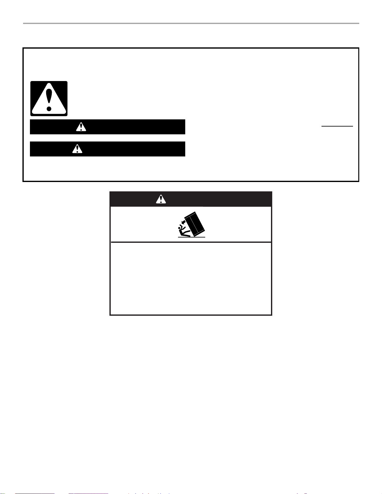
Tip Over Hazard
Refrigerator is top heavy and tips easily when not
completely installed.
Keep doors taped closed until refrigerator is
completely installed.
Use two or more people to move and install
refrigerator.
Failure to do so can result in death or serious injury.
3
MODELS
2320680B 2/08
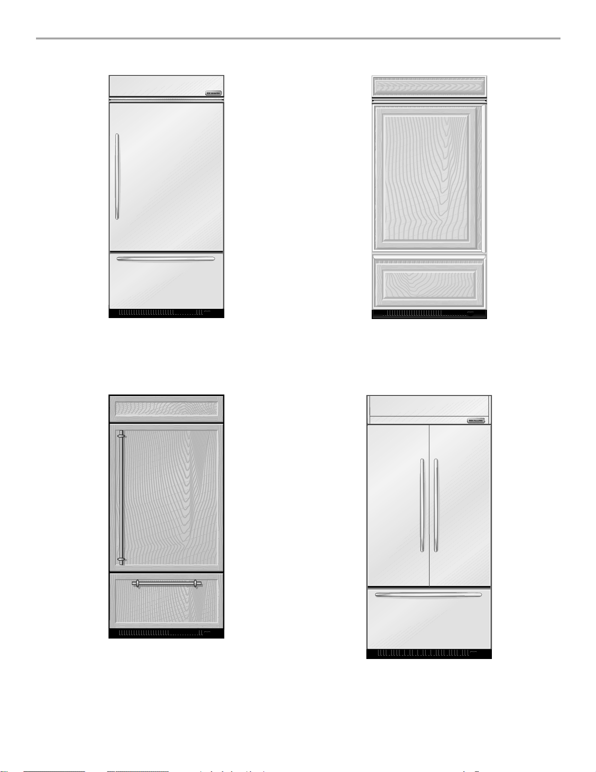
Architect® Series (36" [91.4 cm] Models)
Features wraparound styling that complements the contoured
door handles. This series provides a warm commercial-looking
built-in refrigerator.
KBRC36FTS KBLC36FTS
Classic Series (36" [91.4 cm] Models)
Features traditional style trim, factory-installed, to provide a
“framed” look. This series requires the installation of custom panels
that are not included.
KBRS36FTB KBRS36FTX KBLS36FTB
KBLS36FTX
Overlay Series (36" [91.4 cm] Models)
Features factory-installed, overlay style trim, to provide a
“frameless” look. This series requires the installation of custom
panels, handles, and standoffs.
KBRO36FTX KBLO36FTX
4
Architect® Series (42" [106.7 cm] Models)
Features wraparound styling that complements the contoured door
handles. This series provides a warm commercial-looking built-in
refrigerator.
KBFC42FTS
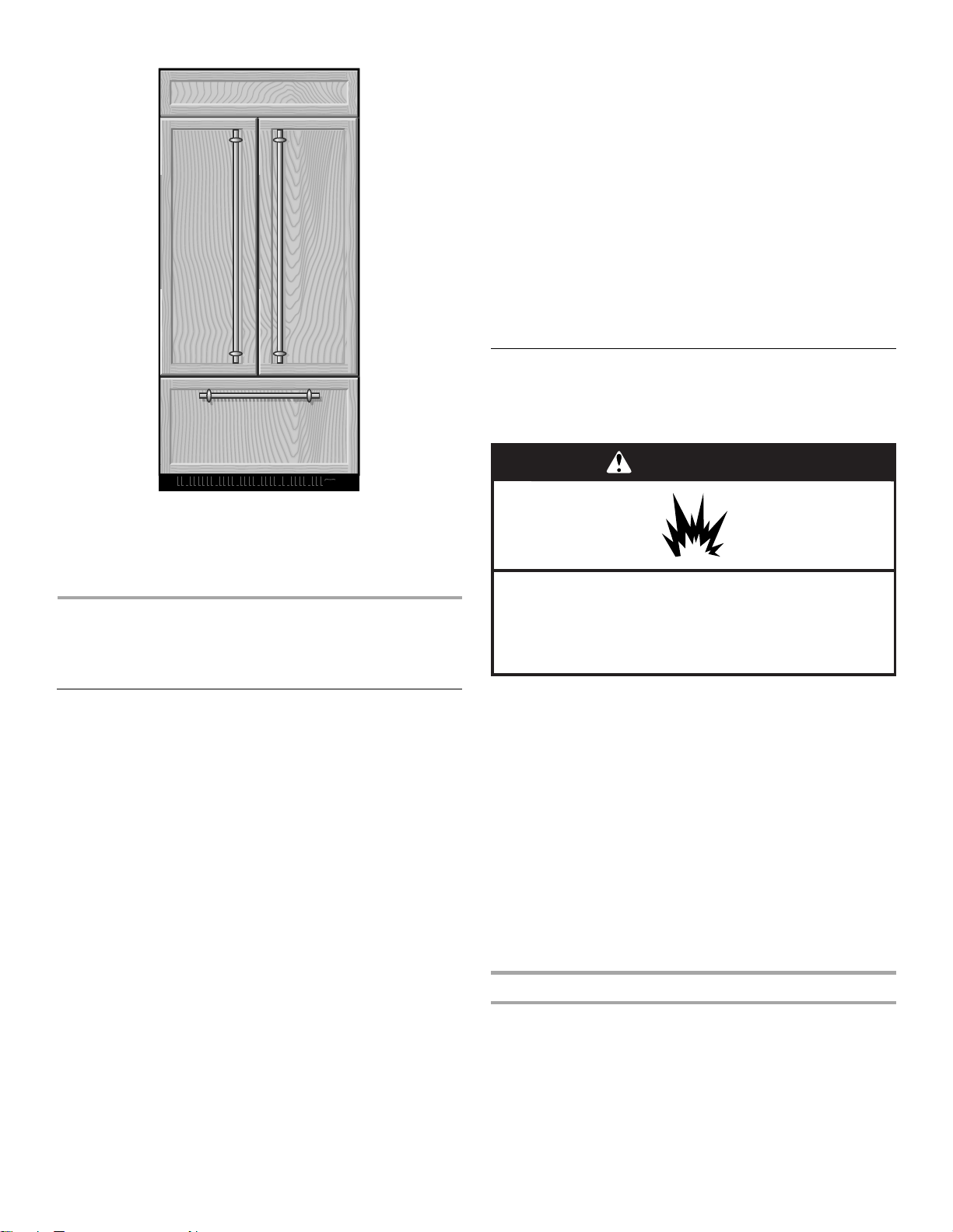
Overlay Series (42" [106.7 cm] Models)
2320680B 2/08
Features factory-installed, overlay style trim, to provide a
“frameless” look. This series requires the installation of custom
panels, handles, and standoffs.
KBFO42FTX
INSTALLATION
REQUIREMENTS
PARTS NEEDED:
■ Six #8 x 3" (7.6 cm) wood screws (longer screws may be needed)
■ One or two 2" x 4" x 32" (5 cm x 10 cm x 81 cm) wood board(s)
■ Order factory panels, make custom panels or consult a
qualified cabinetmaker or carpenter to make the panels.
Classic Series: Order factory panels, make custom panels, or
consult a qualified cabinetmaker or carpenter to make the
panels. See “Installation Requirements” for more information.
Overlay Series: Make custom panels, or consult a qualified
cabinetmaker or carpenter to make the panels. See
“Installation Requirements” for more information.
®
Architect
■ If you are connecting the water line directly to copper tubing
Series is shipped complete.
and not to a shutoff valve, you need a ferrule, a union, and a
¹⁄₄" compression fitting.
Location Requirements
The refrigerator can be recessed in an opening between cabinets
or installed at the end of a cabinet run using a side panel to
enclose the refrigerator.
WARNING
Explosion Hazard
Keep flammable materials and vapors, such as
gasoline, away from refrigerator.
Failure to do so can result in death, explosion, or fire.
Tools and Parts
IMPORTANT:
■ Installer: Leave Installation Instructions with the homeowner.
■ Homeowner: Keep Installation Instructions for future
reference. Save these Installation Instructions for the local
electrical inspector’s use.
TOOLS NEEDED:
Gather the required tools and parts before starting installation.
Read and follow the instructions provided with any tools listed
here.
■ Cordless drill ■ To rx
■ Drill bits ■ ¹¹⁄₃₂" nut driver
■ Two adjustable
■ ³⁄₈", ¹⁄₄", and ¹⁄₂" open-end
wrenches
■ Phillips screwdriver ■ ⁵⁄₃₂" Allen wrench
■ Small level ■ ¹⁄₄" and ⁵⁄₁₆" socket drivers
■ Appliance dolly ■ Tape mea sur e
■ Utility knife
®†
T15 and T27 screwdrivers
wrenches
IMPORTANT:
■ Observe all governing codes and ordinances.
■ It is recommended that you do not install the refrigerator near
an oven, radiator, or other heat source.
■ Do not install in a location where the temperature will fall
below 55°F (13°C).
■ Floor must support the refrigerator weight, more than 600 lbs
(272 kg), door panels and contents of the refrigerator.
■ Ceiling height must allow for side tipping radius. See “Tipping
Radius.”
■ Location should permit door to open fully. See “Door Swing
Dimensions.”
■ Location must permit top grille removal. See “Opening
Dimensions.”
Opening Dimensions
■ To avoid tipping during use, the solid soffit must be within 1"
(2.5 cm) maximum above the refrigerator. If the solid soffit is
higher than 1" (2.5 cm) or one is not available, then the
refrigerator must be braced.
If the anti-tip boards are needed, they must be attached to
the rear wall studs 80" to 90" (203 to 229 cm) above the floor.
See “Install Anti-Tip Boards” for more information.
†®TORX is a registered trademark of Textron Innovations Inc.
5
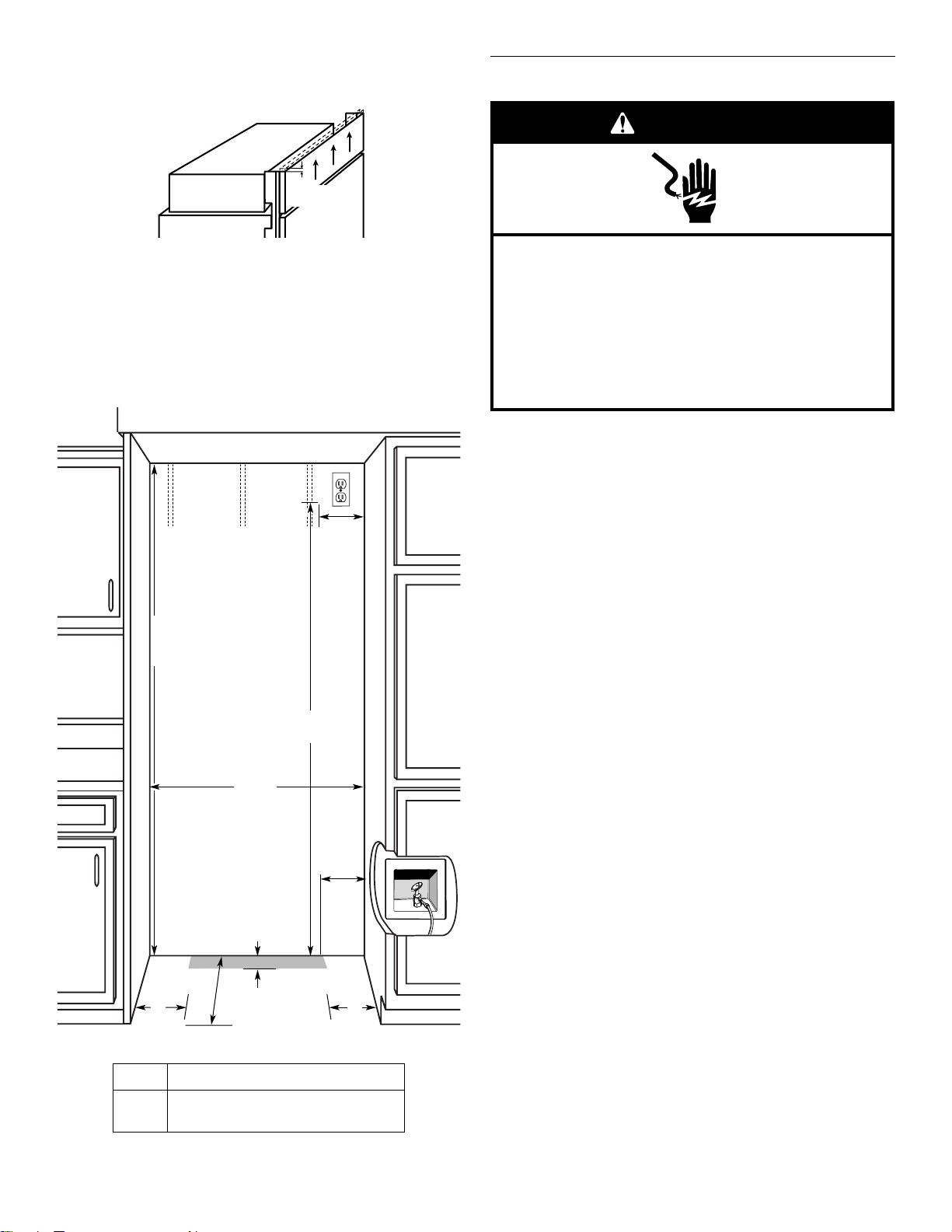
NOTE: A clearance of ¹⁄₂" (1.3 cm) must be maintained in front
2320680B 2/08
of the refrigerator’s side trim in order for the top grille to be
removed.
¹⁄₂"
(1.3 cm)
Electrical Requirements
WARNING
■ A grounded 3 prong electrical outlet should be placed within
4" (10.2 cm) of the right side cabinets or end panel. See
“Electrical Requirements” for additional information.
■ The water shutoff should be located in the base cabinet on
either side of the refrigerator or some other easily accessible
area. If the water shutoff valve is not in the cabinets, the
plumbing for the water line can come through the floor or the
back wall. See “Water Supply Requirements” for more
specific information.
80" - 90"
(203-229 cm)
83¹⁄₂" (212.1 cm) min.
³⁄₄" (215 cm) max.
84
to bottom of solid soffit
A
Width
(see chart following)
4"
(10.2 cm)
77"
(196 cm)
Electrical Shock Hazard
Plug into a grounded 3 prong outlet.
Do not remove ground prong.
Do not use an adapter.
Do not use an extension cord.
Failure to follow these instructions can result in death,
fire, or electrical shock.
Before you move your refrigerator into its final location, it is
important to make sure you have the proper electrical
connection.
Recommended Grounding Method
A 115 Volt, 60 Hz., AC only, 15- or 20-amp fused, grounded
electrical supply is required. It is recommended that a separate
circuit serving only your refrigerator be provided. Use an outlet
that cannot be turned off by a switch. Do not use an
extension cord.
IMPORTANT: If this product is connected to a GFCI (Ground
Fault Circuit Interrupter) protected outlet, nuisance tripping of the
power supply may occur, resulting in loss of cooling. Food quality
and flavor may be affected. If nuisance tripping has occurred,
and if the condition of the food appears poor, dispose of it.
NOTE: Before performing any type of installation, cleaning, or
removing a light bulb, remove the top grille and turn the master
power switch to OFF or disconnect power at the circuit breaker
box.
When you are finished, turn ON the master power switch or
reconnect power at the circuit breaker box. Then reset the control
to the desired setting.
6"
(15.2 cm)
Model Width A (as shown above)
36
42
NOTE: Flooring under refrigerator must be at same level as the
room.
6
1"
(2.54 cm)
24"
(60.96 cm) min.
35¹⁄₂" (90.2 cm)
41¹⁄₂" (105.4 cm)
6"
(15.2 cm)
6"
(15.2 cm)
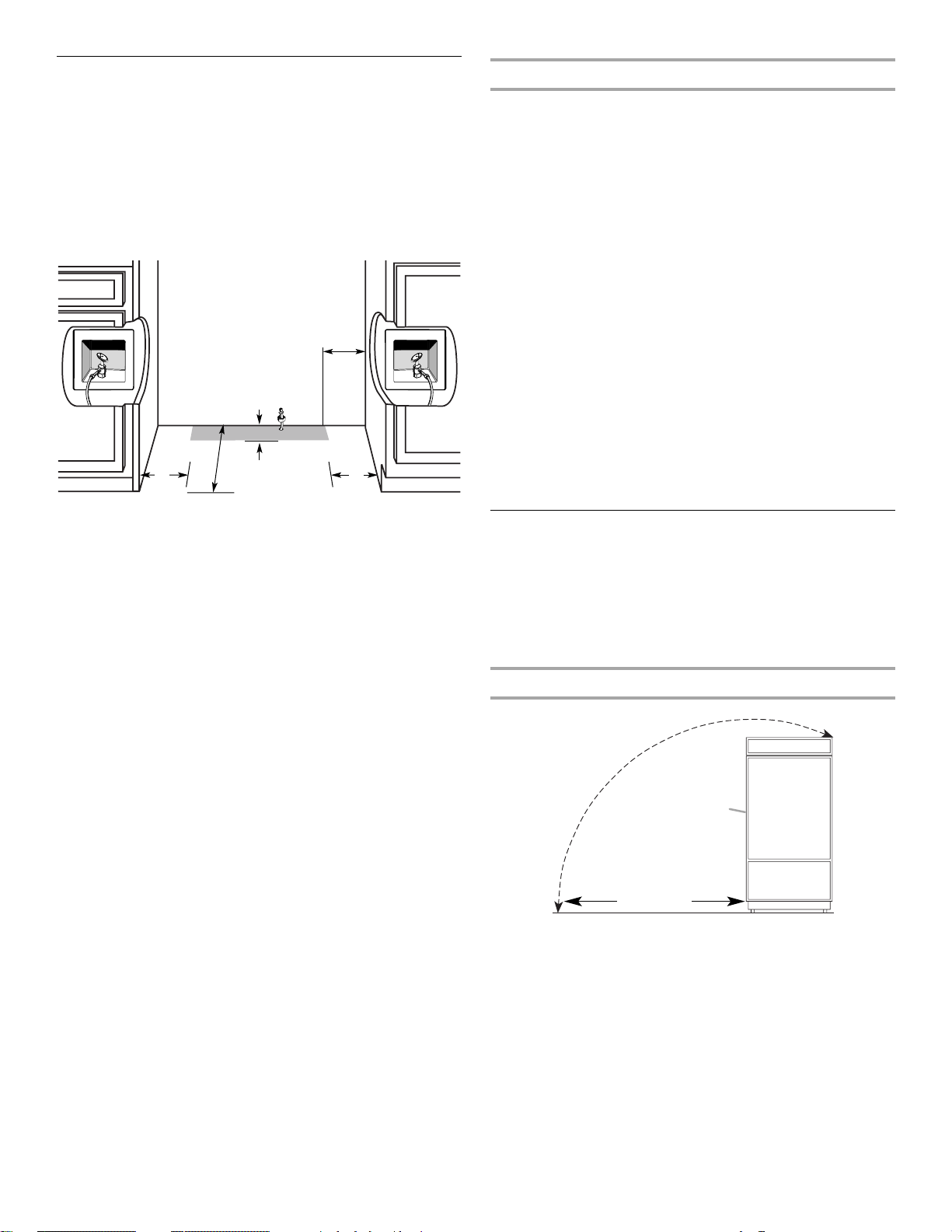
Water Supply Requirements
2320680B 2/08
■ All installations must meet local plumbing code requirements.
■ The water shutoff should be located in the base cabinet on
either side of the refrigerator or some other easily accessible
area. The right-hand side is recommended. The access hole
through the cabinet must be within ¹⁄₂" (12.7 mm) of the rear
wall.
NOTE: If the water shut off valve is in the back wall behind
the refrigerator, it must be at an angle so that the tube is not
kinked when the refrigerator is pushed into its final position.
6"
(15.2 cm)
6"
(15.2 cm)
■ If the water shutoff valve is not in the cabinets, the plumbing
24"
(60.96 cm) min.
for the water line can come through the floor. A ¹⁄₂" (12.7 mm)
hole for plumbing should be drilled at least 6" (15.2 cm) from
the right or left hand side cabinet or panel. On the floor, the
hole should be no more than 1" (2.54 cm) away from the back
wall. See “Connect the Water Supply.”
■ If additional tubing is needed, use copper tubing and check
for leaks. Install the copper tubing only in areas where the
household temperatures will remain above freezing.
■ Do not use a piercing-type or ³⁄₁₆" (4.76 mm) saddle valve
which reduces water flow and clogs more easily.
NOTE: Your refrigerator dealer has a kit available with a ¹⁄₄"
(6.35 mm) saddle-type shutoff valve, a union, and copper
tubing. Before purchasing, make sure a saddle-type valve
complies with your local plumbing codes.
1"
(2.54 cm)
6"
(15.2 cm)
Water Pressure
A cold water supply with water pressure between 30 and 120 psi
(207 and 827 kPa) is required to operate the water dispenser and
ice maker. If you have questions about your water pressure, call a
licensed, qualified plumber.
Reverse Osmosis Water Supply
IMPORTANT: The pressure of the water supply coming out of a
reverse osmosis system going to the water inlet valve of the
refrigerator needs to be between 30 and 120 psi
(207 and 827 kPa).
If a reverse osmosis water filtration system is connected to your
cold water supply, the water pressure to the reverse osmosis
system needs to be a minimum of 40 to 60 psi (276 to 414 kPa).
If the water pressure to the reverse osmosis system is less than
40 to 60 psi (276 to 414 kPa):
■ Check to see whether the sediment filter in the reverse
osmosis system is blocked. Replace the filter if necessary.
■ Allow the storage tank on the reverse osmosis system to refill
after heavy usage.
■ If your refrigerator has a water filter cartridge, it may further
reduce the water pressure when used in conjunction with a
reverse osmosis system. Remove the water filter cartridge.
If you have questions about your water pressure, call a licensed,
qualified plumber.
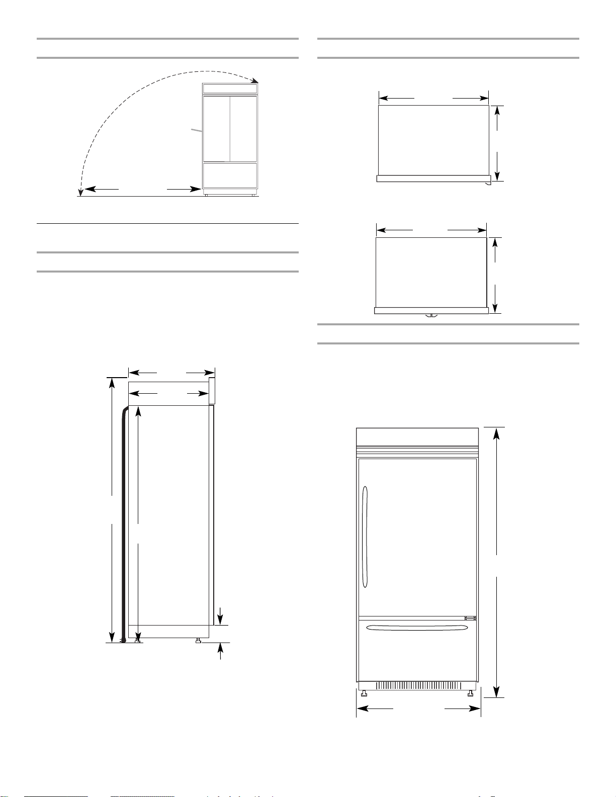
Tipping Radius
Be sure there is adequate ceiling height to stand the refrigerator
upright when it is moved into place.
■ The dolly wheel height must be added to the tipping radius
when a dolly is used.
■ If needed, the tipping radius can be reduced. See “Reduce
Tipping Radius.”
Side Tipping Radius (36" [91.4 cm] Models)
A
90¹⁄₂"
(229.9 cm)
A. Tip this side only
7
Side Tipping Radius (42" [106.7 cm] Models)
2320680B 2/08
Top Vi ew
36" (91.4 cm) Models
35¹⁄₄"
(89.5 cm)
A
93"
(236.2 cm)
A. Tip this side only
Product Dimensions
Side View
■ The depth from the front of the top grille to the back of the
refrigerator cabinet is 25³⁄₈" (64.5 cm).
■ The power cord is 84" (213 cm) long.
■ The water line attached to the back of the refrigerator is 5 ft
(1.5 m) long. Height dimensions are shown with leveling legs
extended ¹⁄₈" (3 mm) below the rollers.
25³⁄₈"
(64.5 cm)
23¹⁄₂"
(59.7 cm)
25³⁄₈"
(64.5 cm)
42" (106.7 cm) Models
41
¹⁄₄"
(105 cm)
25³⁄₈"
(64.5 cm)
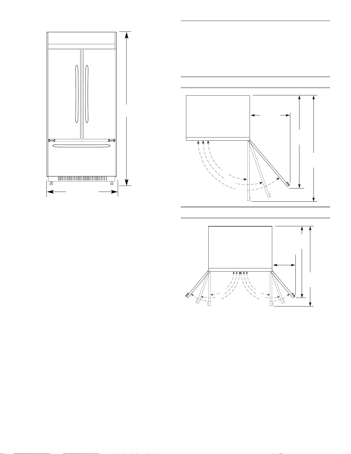
Front View
■ Width dimensions were measured from trim edge to trim
edge.
■ Height dimensions are shown with leveling legs extended ¹⁄₈"
(3 mm) below the rollers.
36" (91.4 cm) Models
*83³⁄₈"
(211.8 cm)
*When leveling legs are fully extended to 1¹⁄₄" (3.2 cm) below
rollers, add 1¹⁄₈" (2.9 cm) to the height dimensions.
8
84" (213.4 cm)
Power Cord
¹⁄₂" (8.9 cm)
*3
*83³⁄₈"
(211.8 cm)
36¹⁄₄" (92 cm)
*When leveling legs are fully extended to 1¹⁄₄" (3.2 cm) below
rollers, add 1¹⁄₈" (2.9 cm) to the height dimensions.
42" (106.7 cm) Models
2320680B 2/08
Door Swing Dimensions
The location must permit the door to open to a minimum of 90°.
Allow 4¹⁄₂" (11.4 cm) minimum space between the side of the
refrigerator and a corner wall.
NOTE: More clearance may be required if you are using overlay
panels or custom handles.
To adjust the door swing, see “Adjust Door Swing.”
36" (91.4 cm) Models
*83³⁄₈"
(211.8 cm)
42¹⁄₄" (107.3 cm)
*When leveling legs are fully extended to 1¹⁄₄" (3.2 cm) below
rollers, add 1¹⁄₈" (2.9 cm) to the height dimensions.
90˚
110˚
130˚
42" (106.7 cm) Models
23"
(58 cm)
(102.7 cm)
¹⁄₂"
13
(34.3 cm)
51"
(130 cm)
59"
(150 cm)
40⁷⁄₁₆"
110˚
130˚
90˚
44¹⁄₄"
(112.3 cm)
90˚
110˚
130˚
9
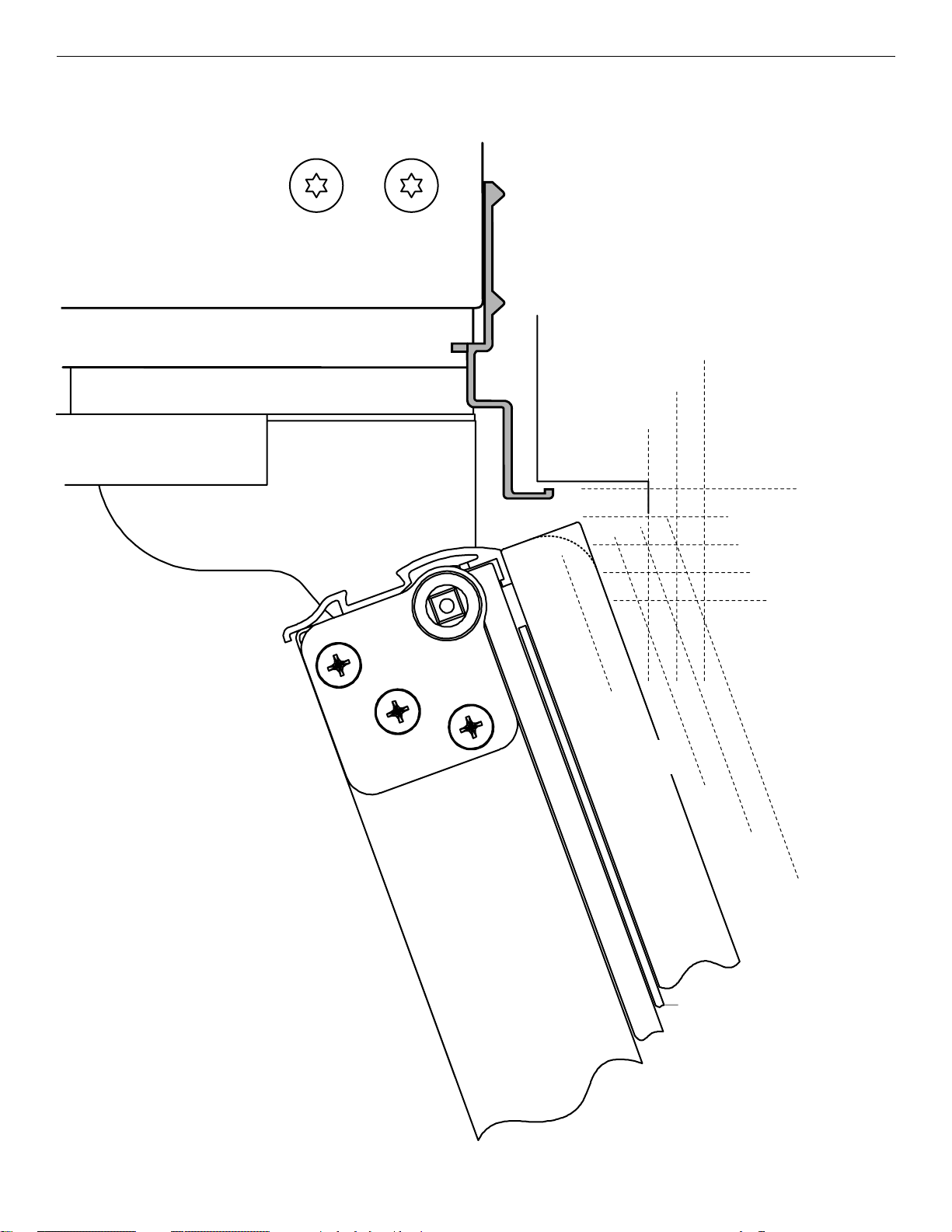
Overlay Series Door Panel & Cabinetry Clearance (36" [91.4 cm] Models)
2320680B 2/08
The custom door panels and adjacent cabinetry must be designed so that there is sufficient clearance for the doors to swing open. If
the refrigerator is to be installed close to the wall, see “Door Swing 90°” on next page.
Door Swing 110˚
Actual Size
Refrigerator to
Cabinetry Clearance
Refrigerator
Side Trim
1
/2"
1
(3.8 cm)
1
1
/4"
(3.2 cm)
1"
(2.5 cm)
Cabinetry
1
/4" (6.35 mm)
Hinge
1
/2" (1.3 cm)
3
/4" (1.9 cm)
NOTE: For Overlay Series models, rout the
hinge side of the custom door panels to a
radius that is equal to at least half the
thickness of the panel if a 130˚ door swing is
desired. See “Adjust Doors.”
Door
1
/2"
(1.3 cm)
Backer Panel
3
/4"
(1.9 cm)
Overlay Panel
(2.5 cm)
Spacer Panel
1"
1" (2.5 cm)
NOTE: Allow ¹⁄₂"
(1.3 cm) clearance
between overlay
panel and cabinetry.
1
1
/4"
(3.2 cm)
1
/2"
1
(3.8 cm)
When the doors are closed the refrigerator will extend beyond the face of the adjacent cabinetry to some degree.
10
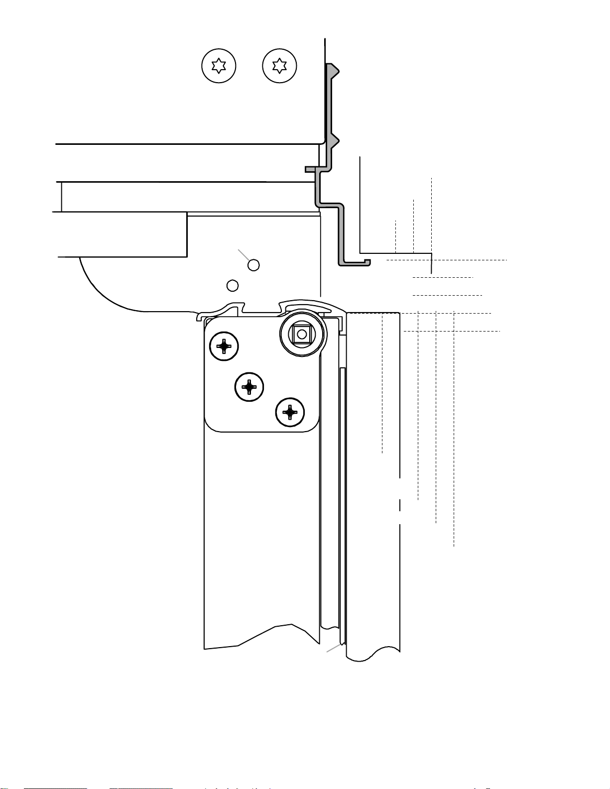
90˚ Door
2320680B 2/08
Stop Position
Hinge
Door Swing 90˚
Actual Size
Refrigerator to
Cabinetry Clearance
Refrigerator
Side Trim
3
/4"
(1.9 cm)
1
/2"
(1.3 cm)
Cabinetry
1"
(2.5 cm)
1
/4" (6.35 mm)
1
/2" (1.3 cm)
3
/4" (1.9 cm)
1" (2.5 cm)
1
/2"
(1.3 cm)
3
/4"
(1.9 cm)
1"
(2.5 cm)
1
1
Door
Backer Panel
Overlay Panel
/4"
(3.2 cm)
1
/2"
1
(3.8 cm)
Spacer Panel
Allow a minimum of 4¹⁄₂" (11.4 cm) of space between the side of the refrigerator and a corner wall. More clearance may be needed if
thicker custom panels or custom handles are used. Do not overlook baseboards.
11
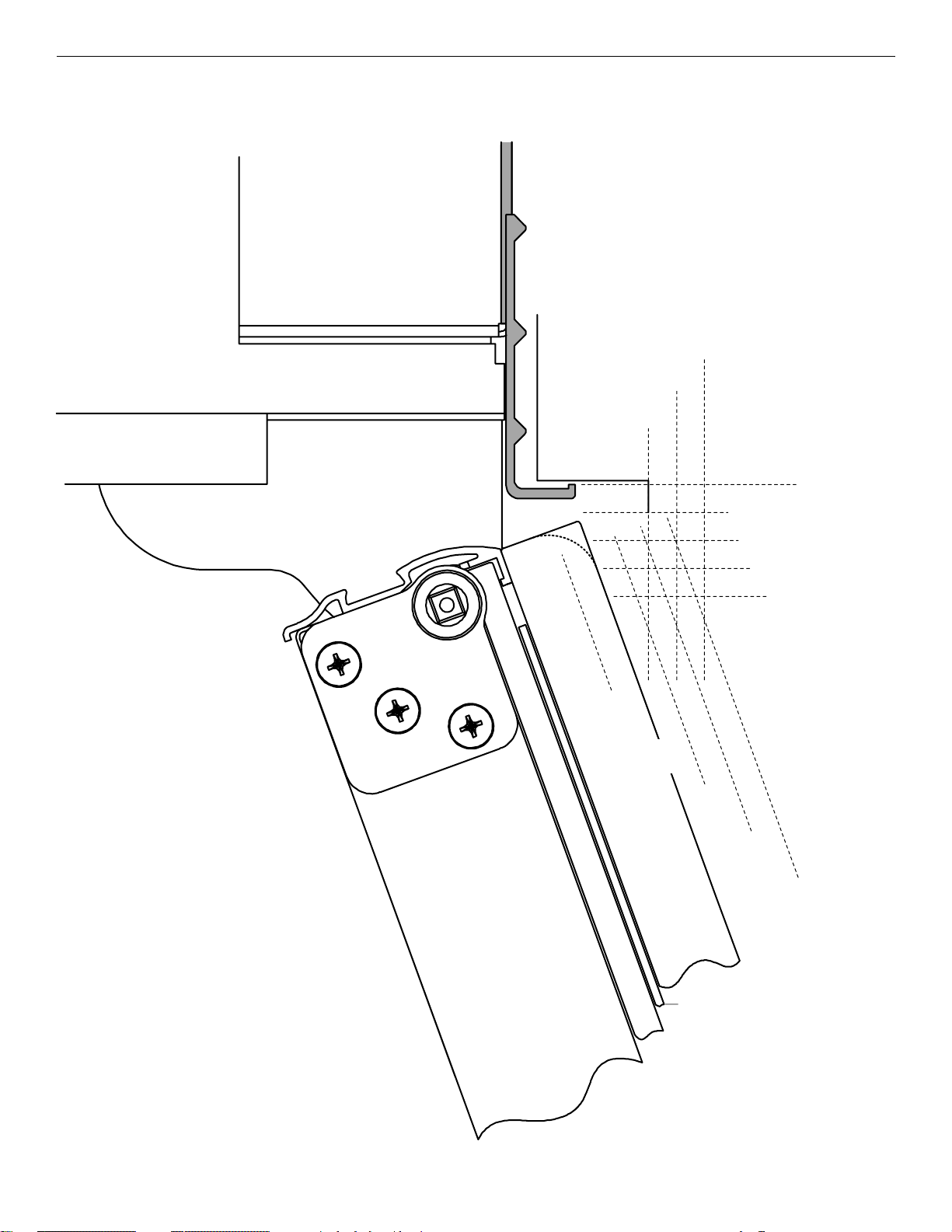
Overlay Series Door Panel & Cabinetry Clearance (42" [106.7 cm] Models)
2320680B 2/08
The custom door panels and adjacent cabinetry must be designed so that there is sufficient clearance for the doors to swing open. If
the refrigerator is to be installed close to the wall, see “Door Swing 90°” on next page.
Door Swing 110˚
Actual Size
Refrigerator to
Cabinetry Clearance
Refrigerator
Side Trim
1
/2"
1
(3.8 cm)
1
1
/4"
(3.2 cm)
1"
(2.5 cm)
Cabinetry
1
/4" (6.35 mm)
Hinge
1
/2" (1.3 cm)
3
/4" (1.9 cm)
NOTE: For Overlay Series models, rout the
hinge side of the custom door panels to a
radius that is equal to at least half the
thickness of the panel if a 130˚ door swing is
desired. See “Adjust Doors.”
Door
1
/2"
(1.3 cm)
Backer Panel
3
/4"
(1.9 cm)
Overlay Panel
(2.5 cm)
Spacer Panel
1"
1" (2.5 cm)
NOTE: Allow ¹⁄₂"
(1.3 cm) clearance
between overlay
panel and cabinetry.
1
1
/4"
(3.2 cm)
1
/2"
1
(3.8 cm)
When the doors are closed the refrigerator will extend beyond the face of the adjacent cabinetry to some degree.
12
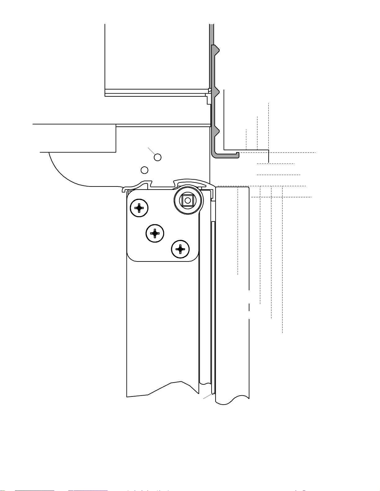
90˚ Door
2320680B 2/08
Stop Position
Hinge
Door Swing 90˚
Actual Size
Refrigerator to
Cabinetry Clearance
Refrigerator
Side Trim
3
/4"
(1.9 cm)
1
/2"
(1.3 cm)
Cabinetry
1"
(2.5 cm)
1
/4" (6.35 mm)
1
/2" (1.3 cm)
3
/4" (1.9 cm)
1" (2.5 cm)
1
/2"
(1.3 cm)
3
/4"
(1.9 cm)
1"
(2.5 cm)
1
1
Door
Backer Panel
Overlay Panel
/4"
(3.2 cm)
1
/2"
1
(3.8 cm)
Spacer Panel
Allow a minimum of 4¹⁄₂" (11.4 cm) of space between the side of the refrigerator and a corner wall. More clearance may be needed if
thicker custom panels or custom handles are used. Do not overlook baseboards.
13
Overlay Series Custom Panels
2320680B 2/08
Custom overlay panels allow you to blend the exterior of your
refrigerator into the overall kitchen décor and to use custom
handles for additional design flexibility.
The custom panels must have backer panels attached in order to
mount them to the refrigerator. It is most common to work with
three panels, as shown in the following graphic: a decorative
overlay panel, a ¹/₈" (3.18 mm) spacer panel or spacer strips and
a ¹/₄" (6.35 mm) backer panel.
Overlay Panel
5
/8" to 3/4"
(15.88 to
19.05 mm)
(3.18 mm)
1
/8"
Spacer Panel
Backer Panel
1
/4"
(6.35 mm)
Spacer Panel
1
/8"
(3.18 mm)
Overlay Panel
Backer Panel
1" minimum
(2.54 cm)
Offset Dimension
Door/Grille Trim
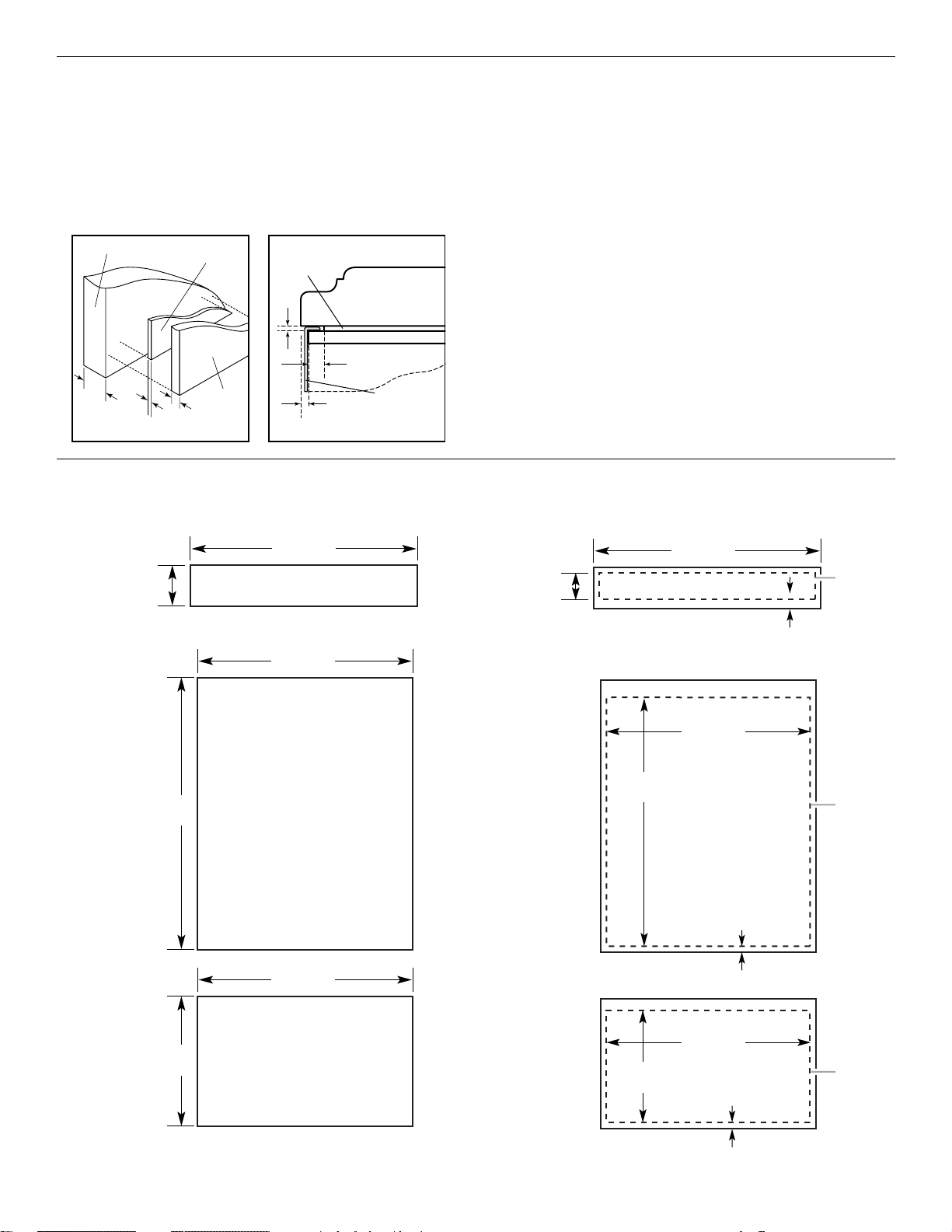
Custom Overlay Panel Dimensions
Custom Overlay Panels (36" [91.4 cm] Models) Custom Backer Panels (36" [91.4 cm] Models)
In some cases, your cabinet manufacturer may choose to work
with one panel routed for the different dimensions. Follow these
panel dimension and placement instructions to be sure that the
custom overlay panels will fit properly.
IMPORTANT:
■ For 36" (91.4 cm) models, the refrigerator door overlay panel
cannot exceed 50 lbs (23 kg) and the freezer drawer overlay
panel cannot exceed 20 lbs (9.1 kg).
■ For 42" (106.7 cm) models, the refrigerator door overlay panel
cannot exceed 30 lbs (13.5 kg) and the freezer drawer overlay
panel cannot exceed 25 lbs (11.4 kg).
■ The weight of the top grille overlay panel cannot exceed
10 lbs (4.5 kg) for both models.
To minimize panel weight, you may use 2" (5.08 cm) spacer strips
around the perimeter in place of full-sheet solid spacer panels.
The spacer strips must be set in at least 1" (2.54 cm) from the
top, bottom and side edges of the backer panel. If you use
spacer strips, it is also recommended that you use two 2"
(5.08 cm) strips horizontally centered for added support.
7¹⁄₄"
(18.42 cm)
(129.86 cm)
51¹⁄₈"
34³⁄₄"
(88.27 cm)
TOP GRILLE PANEL
Maximum Weight: 10 lbs (4.5 kg)
34³⁄₄"
(88.27 cm)
REFRIGERATOR DOOR PANEL
Maximum Weight: 50 lbs (23 kg)
34³⁄₄"
(88.27 cm)
6³⁄₁₆"
(15.72 cm)
49¹⁄₈"
(124.78 cm)
33³⁄₄"
(85.73 cm)
34¹⁄₄"
(87.00 cm)
Center
Backer
Panel
left to
right
Bottom Offset
³⁄₈" (9.5 mm)
Center
Backer
Panel
left to
right
Bottom Offset
⁷⁄₁₆" (11.1 mm)
20³⁄₄"
(52.71 cm)
14
FREEZER DOOR PANEL
Maximum Weight: 20 lbs (9.1 kg)
20³⁄₁₆"
(51.28 cm)
34¹⁄₄"
(87.00 cm)
Center
Backer
Panel
left to
right
Bottom Offset
¹⁄₄" (6.35 mm)
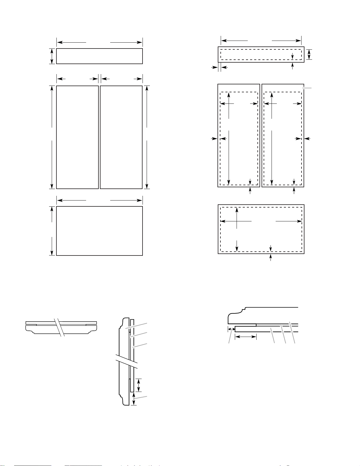
Custom Overlay Panels (42" [106.7 cm] Models) Custom Backer Panels (42" [106.7 cm] Models)
2320680B 2/08
395/
8"
(100.6 cm)
1
/
2"
195/
8"
(49.85 cm)
493/
16"
(124.93 cm)
Bottom
Offset
(1.27 cm)
Bottom Offset
1
1
/
2"
7
¹⁄₄
(18.4 cm)
51
(130.2 cm)
"
REFRIGERATOR
¹⁄₄
"
DOOR PANEL
Maximum Weight:
30 lbs (13.5 kg)
40
⁷⁄₁₆
"
(102.7 cm)
TOP GRILLE PANEL
Maximum Weight: 10 lbs (4.5 kg)
20"
(50.8 cm)
20"
(50.8 cm)
REFRIGERATOR
DOOR PANEL
Maximum Weight:
30 lbs (13.5 kg)
51
¹⁄₄
"
(130.2 cm)
Side
Offset
3
/
16"
(4.7 mm)
Side Offset
3
/
8" (9.5 mm)
195/
8"
(49.85 cm)
493/
16"
(124.93 cm)
Bottom
Offset
(1.27 cm)
61/
(15.9 cm)
/
2" (1.27 cm)
Exterior
Panel
extends
above
door.
Side
Offset
3
/
16"
(4.7 mm)
4"
40
⁷⁄₁₆
"
(102.7 cm)
40"
20
¹⁄₄
(51.4 cm)
"
FREEZER DOOR PANEL
Maximum Weight: 25 lbs (11.4 kg)
197/
(101.6 cm)
8"
(50.48 cm)
Offset all sides
3
/
16" (4.7 mm)
Spacer Panels (All models)
NOTE: Spacer panels must be at least 1" (2.54 cm) from the top, bottom, and side edges of the backer panel.
3-Piece Grille Overlay Panel Configuration 3-Piece Door Overlay Panel Configuration
Top View Side View
D
C
1"
(2.54 cm)
¹₄
" (6.25 mm) Backer panel
¹₈
" (3.18 mm) Spacer panel
³₄
" (1.92 cm) Decorative overlay panel
B
A. Offset dimension
¹₄
" (6.25 mm) Backer panel
B.
¹₈
" (3.18 mm) Spacer panel
C.
³₄
" (1.92 cm) Decorative
D.
overlay panel
B
1"
(2.54 cm)
A
A. Offset dimension
B.
C.
D.
1-Piece Overlay Panel Configuration
In some cases, your cabinet manufacturer may choose to work
with one panel routed for the different dimensions. Follow these
panel dimesions and placement instructions to be sure that the
custom overlay panels will fit properly.
DA C
15
Classic, Architect®, and Overlay Series
2320680B 2/08
Factory Panels and Kits (36" [91.4 cm] Models)
All factory parts are available through your KitchenAid dealer or
by calling KitchenAid Parts and Accessories at 1-800-442-9991.
In Canada, call 1-800-807-6777.
Factory Door Panel Kits
Three kits containing colored acrylic or stainless steel door and
top grille panels are available. Follow the kit instructions for
installing the panels.
NOTE: Panel kits are not required for factory-installed stainless
steel panel models.
Color 36" (91.4 cm)
White #W10163652
Black #W10163654
Stainless Steel #W10163656
Classic Series Custom Panels (36" [91.4 cm]
Models)
If you plan to install custom wood panels, you will need to create
the panels yourself or consult a qualified cabinetmaker or
carpenter. See dimension drawings for panel specifications.
IMPORTANT: Panels weighing more than recommended may
cause damage to your refrigerator.
NOTE: Dimensions shown have a (±) ¹⁄₁₆" (1.5 mm) tolerance.
Panels that are more than ¹⁄₄" (6.35 mm) thick must be routed. If
panels are less than ¹⁄₄" (6.35 mm) thick, install a filler panel
between the door and the decorative panel.
Top Grille Panel
The top panel should not weigh more than 10 lbs (4.5 kg).
34¹⁄₂"
(87.63 cm)
7¹⁄₄"
(18.4 cm)
Architect® Series 72" (183 cm) Top Grille Panel Kit
A 72" (183 cm) wide Top Grille Panel Kit is available. This kit
allows 2 units (one left-hand swing and one right-hand) to be
installed side by side with a single grille.
Color 72" (183 cm)
Stainless Steel (Architect
®
Series) #W10153554
Extended Door Handle Kits
Use extended door handles when additional finger clearance is
needed between the door handles and custom panel. Follow the
kit instructions for installing the door handles.
Color Left-Hand Swing Right-Hand Swing
White (Classic
Series)
Black (Classic
Series)
Stainless Steel
(Classic Series)
Matte Aluminum
Etched (Classic
Series)
Matte Aluminum
(Overlay Series)
#4396119 #8171424
#4396116 #8171427
#4396118 #8171425
#4396120 #8171423
#4396718
Refrigerator and Freezer Panels
The freezer panel should not weigh more than 20 lbs (9.1 kg). The
refrigerator panel should not weigh more than 50 lbs (22 kg).
34¹⁄₄"
(87 cm)
49"
(124.5 cm)
34¹⁄₄"
(87 cm)
20¹⁄₈"
(51.1 cm)
16
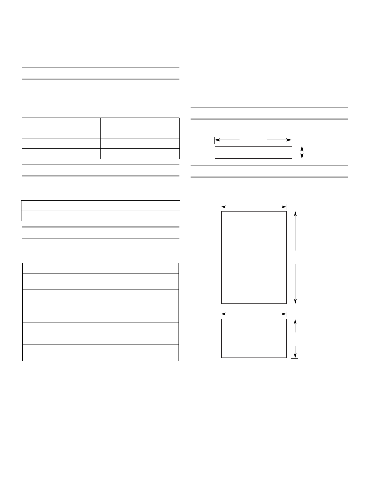
Top Grille Panel – Routing Requirements
¹⁄₂" (1.3 cm)
min.
¹⁄₄"
(6.35 mm)
max.
2320680B 2/08
If the custom panels are thicker than ¹⁄₄" (6.35mm), the top and
bottom edges of the top panel should be edge routed ¹⁄₂"
(1.27 cm) and ³⁄₈" (9.5 mm), respectively. Both ends should be
edge routed ⁷⁄₈" (2.2 cm) as shown.
¹⁄₄"
(6.35 mm)
max.
Top
Grille
Top
Grille
¹⁄₄
"
(6.35 mm)
max.
If an extended handle kit is used, rout the handle side ¹⁄₄"
(6.35 mm). All other routing dimensions would remain the same
as the standard handle. Make sure your product location will
allow doors with extended handles to be opened to 90 degrees.
See “Door Swing Dimensions.”
For more information on ordering extended handles, see “Classic
Series Factory Panels and Kits.”
NOTE: For both types of handles, rout the top and bottom edges
of the refrigerator panel ¹⁄₂" (1.27 cm). Rout the bottom of the
freezer panel ¹⁄₂" (1.27 cm).
Door Panel - Side View
⁷⁄₈"
(2.2 cm)
⁷⁄₈"
(2.2 cm)
NOTE: When creating a panel with face detail, the offsets will be
hidden and must be accounted for in order to center the detail in
the top grille.
¹⁄₄"
(6.35 mm) max.
¹⁄₂"
(1.3 cm)
min.
Center face
detail between
offsets
³⁄₈"
(9.5 mm)
min.
Top
Bottom
¹⁄₄"
(6.35 mm) max.
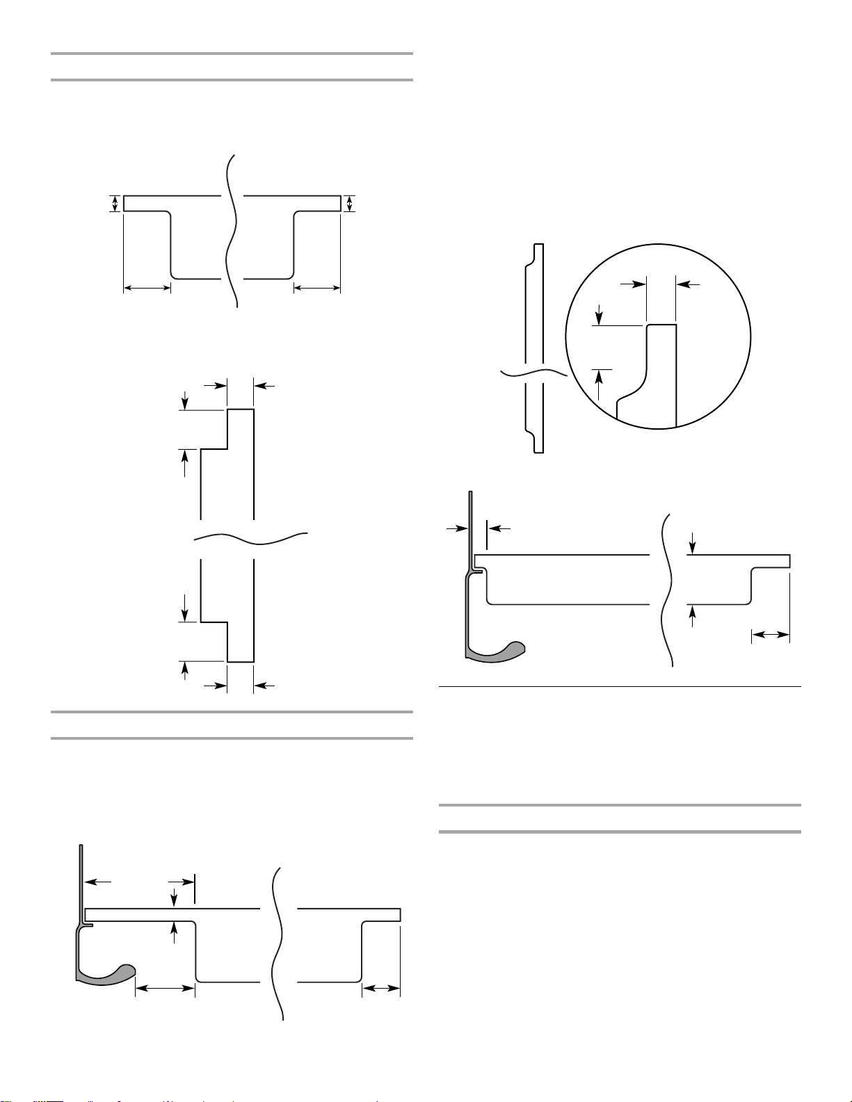
Door Panel – Routing Requirements
If the custom panels are thicker than ¹⁄₄" (6.35 mm), then all edges
of the panels must be routed. If the standard handle is used, rout
the entire handle side of both panels 3¹⁄₄" (8.25 cm) to allow for
finger clearance. Then rout the hinge side of the refrigerator panel
1" (2.54 cm). Rout both sides of the freezer panel 1" (2.54 cm).
Standard Handle – Top View
3¹⁄₄"
(8.25 cm)
min.
¹⁄₄" (6.35 mm) max.
Handle
Door
Panel
2" (5 cm)
min.
Door
Panel
Hinge Side
1"
(2.54 cm)
Panel
Extended Handle - Top View
1"
¹⁄₄"
(6.35 mm)
Door
Panel
Handle
(2.54 cm)
max
Hinge Side
Door
Panel
1"
(2.54 cm)
Classic and Architect® Series
Custom Side Panels
Custom side panels may be needed when not enough space is
available to have cabinets on both sides of the refrigerator or
when the refrigerator is placed and the end of a cabinet run. You
may choose an Inset, Flush, or Recessed Inset panel installation.
Refrigerator and Side Trim Dimensions
The width and height of a side panel are determined by the type
of installation you are planning.
NOTES:
■ The dimensions shown are actual product dimensions
and may not reflect the needed panel installation
dimensions.
■ The side panel should be a minimum of ¹⁄₂" (1.27 cm) thick
to avoid warping.
■ If the opening depth is 25" (63.5 cm) or more, you may
want to install a support board on the rear wall.
17
 Loading...