


KBRS20ETSS
KITCHENAID KBRS20ETSS, KBRS19KTSS, KBRS19KTBL, KBLS22KVSS, KBLS20EVMS User Manual
...
REFRIGERATOR USER INSTRUCTIONS
THANK YOU for purchasing this high-quality product. If you should experience a problem not covered in TROUBLESHOOTING,
please visit our website at www.kitchenaid.com for additional information. If you still need assistance, call us at 1-800-422-1230.
In Canada, visit our website at www.kitchenaid.ca or call us at 1-800-807-6777.
You will need your model and serial number located on the right-hand side of the refrigerator interior.
Para obtener acceso a “Instrucciones para el usuario del refrigerador” en español, o para obtener información adicional de su
producto, visite: www.kitchenaid.com
Tenga listo su número de modelo completo. Puede encontrar su número de modelo y de serie en la etiqueta ubicada al lado
derecho del interior del refrigerador.
Table of Contents / Table des matières
REFRIGERATOR SAFETY................................................................... 1
INSTALLATION INSTRUCTIONS ....................................................... 2
REFRIGERATOR USE ....................................................................... 10
REFRIGERATOR CARE.....................................................................14
TROUBLESHOOTING........................................................................ 15
WATER FILTER CERTIFICATIONS .................................................. 17
PRODUCT DATA SHEETS ................................................................18
WARRANTY........................................................................................ 19
SÉCURITÉ DU RÉFRIGÉRATEUR ................................................... 20
INSTRUCTIONS D’INSTALLATION ................................................. 21
UTILISATION DU RÉFRIGÉRATEUR............................................... 31
ENTRETIEN DU RÉFRIGÉRATEUR ................................................. 35
DÉPANNAGE...................................................................................... 36
FEUILLES DE DONNÉES SUR LE PRODUIT.................................. 39
GARANTIE.......................................................................................... 40
REFRIGERATOR SAFETY
Your safety and the safety of others are very important.
We have provided many important safety messages in this manual and on your appliance. Always read and obey all safety
messages.
This is the safety alert symbol.
This symbol alerts you to potential hazards that can kill or hurt you and others.
All safety messages will follow the safety alert symbol and either the word “DANGER” or “WARNING.”
These words mean:
You can be killed or seriously injured if you don't immediately
DANGER
WARNING
All safety messages will tell you what the potential hazard is, tell you how to reduce the chance of injury, and tell you what can
happen if the instructions are not followed.
W10137649A
follow instructions.
can be killed or seriously injured if you don't
You
instructions.
follow
Downloaded from www.Manualslib.com manuals search engine
IMPORTANT SAFETY INSTRUCTIONS
To reduce the risk of fire, electric shock, or injury to persons when using the refrigerator, follow basic precautions,
WARNING:
including the following:
■
■
Plug into a grounded 3 prong outlet.
■
Do not remove ground prong.
■
Do not use an adapter.
■
Do not use an extension cord.
■
Disconnect power before servicing.
■
Replace all parts and panels before operating.
■
Remove doors from your old refrigerator.
Use nonflammable cleaner.
■
Keep flammable materials and vapors, such as gasoline,
away from refrigerator.
■
Use two or more people to move and install refrigerator.
■
Disconnect power before installing ice maker (on ice maker
kit ready models only).
SAVE THESE INSTRUCTIONS
Proper Disposal of Your Old Refrigerator
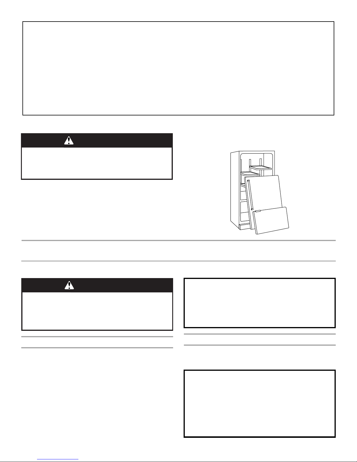
WARNING
Suffocation Hazard
Remove doors from your old refrigerator.
Failure to do so can result in death or brain damage.
IMPORTANT: Child entrapment and suffocation are not problems
of the past. Junked or abandoned refrigerators are still dangerous
– even if they will sit for “just a few days.” If you are getting rid of
your old refrigerator, please follow these instructions to help
prevent accidents.
INSTALLATION INSTRUCTIONS
Unpack the Refrigerator
WARNING
Excessive Weight Hazard
Use two or more people to move and install
refrigerator.
Failure to do so can result in back or other injury.
Before You Throw Away Your Old Refrigerator or Freezer:
■ Take off the doors.
■ Leave the shelves in place so that children may not easily
climb inside.
When Moving Your Refrigerator:
Your refrigerator is heavy. When moving the refrigerator
for cleaning or service, be sure to protect the floor.
Always pull the refrigerator straight out when moving it.
Do not wiggle or “walk” the refrigerator when trying to move
it, as floor damage could occur.
Remove the Packaging
■ Remove tape and glue residue from surfaces before turning
on the refrigerator. Rub a small amount of liquid dish soap
over the adhesive with your fingers. Wipe with warm water
and dry.
■ Do not use sharp instruments, rubbing alcohol, flammable
fluids, or abrasive cleaners to remove tape or glue. These
products can damage the surface of your refrigerator. For
more information, see “Refrigerator Safety.”
■ Properly dispose of packaging.
2
Downloaded from www.Manualslib.com manuals search engine
Clean Before Using
After you remove all of the packaging materials, clean the inside of
your refrigerator before using it. See the cleaning instructions in
“Refrigerator Care.”
Important information to know about glass shelves
and covers:
Do not clean glass shelves or covers with warm water when
they are cold. Shelves and covers may break if exposed to
sudden temperature changes or impact, such as bumping.
For your protection, tempered glass is designed to shatter
into many small, pebble-size pieces. This is normal. Glass
shelves and covers are heavy. Use special care when
removing them to avoid impact from dropping.
Location Requirements
Electrical Requirements
WARNING
Explosion Hazard
Keep flammable materials and vapors, such as
gasoline, away from refrigerator.
Failure to do so can result in death, explosion, or fire.
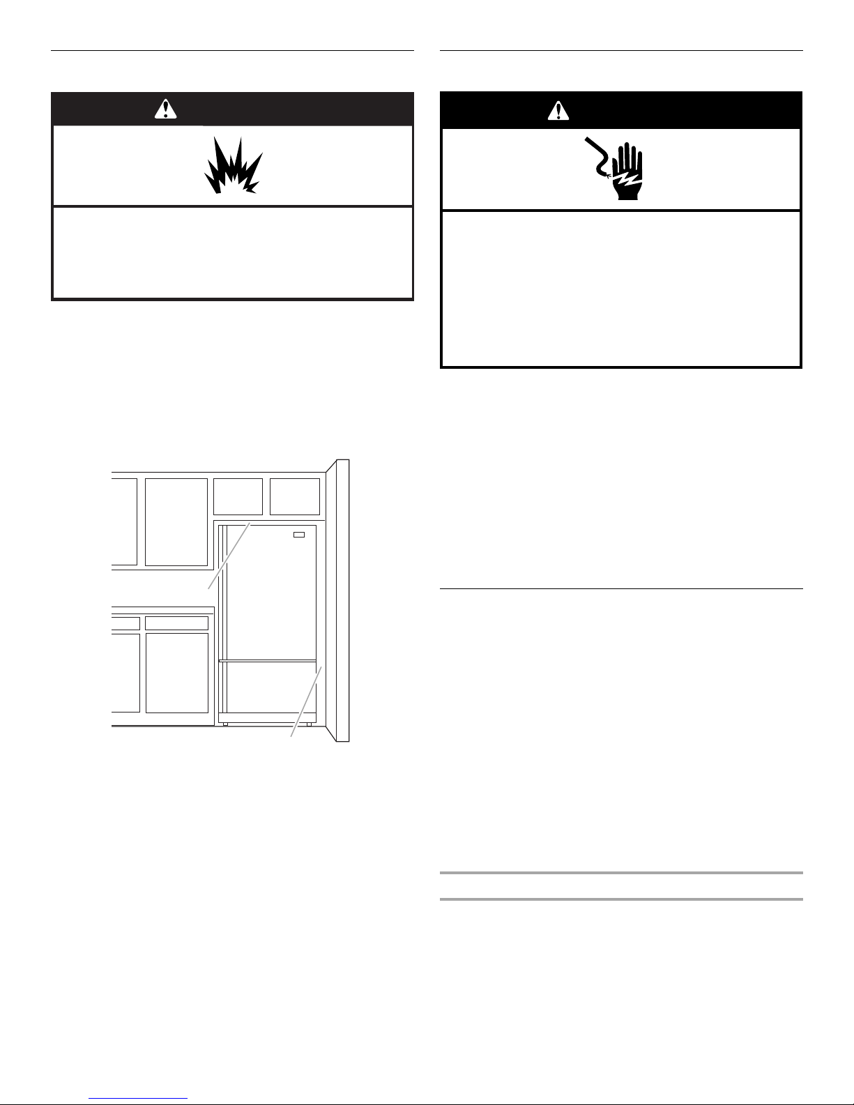
To ensure proper ventilation for your refrigerator, allow for a ¹⁄₂"
(1.25 cm) space at the top and behind the refrigerator. If your
refrigerator has an ice maker, allow extra space at the back for the
water line connections. When installing your refrigerator next to a
fixed wall, leave 2¹⁄₂" (6.3 cm) minimum on the hinge side (some
models require more) to allow for the door to swing open.
NOTE: It is recommended that you do not install the refrigerator
near an oven, radiator, or other heat source. Do not install the
refrigerator in a location where the temperature will fall below 55°F
(13°C).
¹⁄₂" (1.25 cm)
2¹⁄₂" (6.3 cm)
WARNING
Electrical Shock Hazard
Plug into a grounded 3 prong outlet.
Do not remove ground prong.
Do not use an adapter.
Do not use an extension cord.
Failure to follow these instructions can result in death,
fire, or electrical shock.
Before you move your refrigerator into its final location, it is
important to make sure you have the proper electrical connection.
Recommended Grounding Method
A 115 Volt, 60 Hz., AC only 15- or 20-amp fused, grounded
electrical supply is required. It is recommended that a separate
circuit serving only your refrigerator be provided. Use an outlet
that cannot be turned off by a switch. Do not use an
extension cord.
NOTE: Before performing any type of installation, cleaning, or
removing a light bulb, turn the control (Thermostat, Refrigerator or
Freezer Control depending on the model) OFF and then
disconnect the refrigerator from the electrical source. When you
are finished, reconnect the refrigerator to the electrical source and
reset the control (Thermostat, Refrigerator or Freezer Control
depending on the model) to the desired setting.
Water Supply Requirements
Gather the required tools and parts before starting installation.
Read and follow the instructions provided with any tools listed
here.
TOOLS NEEDED:
■ Flat-blade screwdriver
■ ⁷⁄₁₆" and ¹⁄₂" Open-end or two
adjustable wrenches
IMPORTANT:
■ All installations must meet local plumbing code requirements.
■ Do not use a piercing-type or ³⁄₁₆" (4.76 mm) saddle valve
which reduces water flow and clogs more easily.
■ Use copper tubing and check for leaks. Install copper tubing
only in areas where the household temperatures will remain
above freezing.
■ ¹⁄₄" nut driver
■ ¹⁄₄" Drill bit
■ Cordless drill
Downloaded from www.Manualslib.com manuals search engine
Water Pressure
A cold water supply with water pressure of between 35 and
120 psi (241 and 827 kPa) is required to operate the water
dispenser and ice maker. If you have questions about your water
pressure, call a licensed, qualified plumber.
Reverse Osmosis Water Supply
IMPORTANT: The pressure of the water supply coming out of a
reverse osmosis system going to the water inlet valve of the
refrigerator needs to be between 35 and 120 psi (241 and
827 kPa).
3
If a reverse osmosis water filtration system is connected to your
cold water supply, the water pressure to the reverse osmosis
system needs to be a minimum of 40 to 60 psi (276 to 414 kPa).
If the water pressure to the reverse osmosis system is less than
40 to 60 psi (276 to 414 kPa):
■ Check to see whether the sediment filter in the reverse
osmosis system is blocked. Replace the filter if necessary.
■ Allow the storage tank on the reverse osmosis system to refill
after heavy usage.
■ If your refrigerator has a water filter, it may further reduce the
water pressure when used in conjunction with a reverse
osmosis system. Remove the water filter. See “Water Filtration
System.”
If you have questions about your water pressure, call a licensed,
qualified plumber.
Connect the Water Supply
Read all directions before you begin.
IMPORTANT: If you turn the refrigerator on before the water line is
connected, turn the ice maker OFF.
8. Place the free end of the tubing in a container or sink, and turn
ON the main water supply. Flush the tubing until water is clear.
Turn OFF the shutoff valve on the water pipe.
Connect to Refrigerator
Depending on your model, the water line may come down from
the top or up from the bottom. Follow the connection instructions
for your model.
Style 1
1. Remove plastic cap from water valve inlet port. Attach the
copper tube to the valve inlet using a compression nut and
sleeve as shown. Tighten the compression nut. Do not
overtighten. Confirm copper tubing is secure by pulling on
copper tubing.
2. Create a service loop with the copper tubing. Avoid kinks
when coiling the copper tubing. Secure copper tubing to
refrigerator cabinet with a “P” clamp.
A
Connect to Water Line
1. Unplug refrigerator or disconnect power.
2. Turn OFF main water supply. Turn ON nearest faucet long
enough to clear line of water.
3. Find a ¹⁄₂" to 1¹⁄₄" (12.7 mm to 3.18 mm) vertical cold water
pipe near the refrigerator.
IMPORTANT:
■ Make sure it is a cold water pipe.
■ Horizontal pipe will work, but the following procedure
must be followed: Drill on the top side of the pipe, not the
bottom. This will help keep water away from the drill. This
also keeps normal sediment from collecting in the valve.
4. Determine the length of copper tubing you need. Measure
from the connection on the lower right rear of refrigerator to
the water pipe. Add 7 ft (2.1 m) to allow for cleaning. Use ¹⁄₄"
(6.35 mm) O.D. (outside diameter) copper tubing. Be sure both
ends of copper tubing are cut square.
5. Using a cordless drill, drill a ¹⁄₄" hole in the cold water pipe you
have selected.
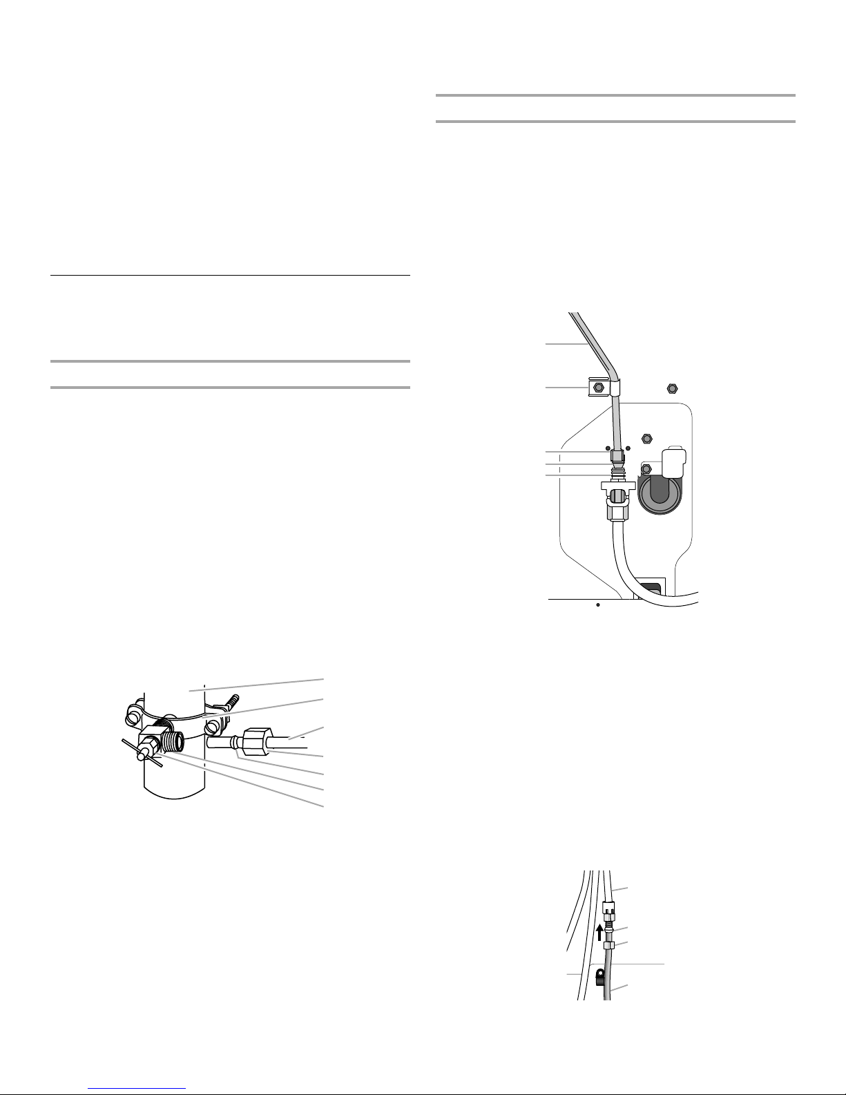
6. Fasten the shutoff valve to the cold water pipe with the pipe
clamp. Be sure the outlet end is solidly in the ¹⁄₄" drilled hole in
the water pipe and that the washer is under the pipe clamp.
Tighten the packing nut. Tighten the pipe clamp screws slowly
and evenly so the washer makes a watertight seal. Do not
overtighten or you may crush the copper tubing.
7. Slip the compression sleeve and compression nut on the
copper tubing as shown. Insert the end of the tubing into the
outlet end squarely as far as it will go. Screw compression nut
onto outlet end with adjustable wrench. Do not overtighten.
A. Cold water pipe
B. Pipe clamp
C. Copper tubing
D. Compression nut
A
B
C
D
E
F
G
E. Compression sleeve
F. Shutoff valve
G. Packing nut
B
C
D
E
A. Copper tubing
B. “P” clamp
C. Compression nut
D. Compression sleeve
E. Water valve inlet port
3. Turn on water supply to refrigerator and check for leaks.
Correct any leaks.
Style 2
1. Create a service loop (minimum diameter of 2 ft [61 cm]) with
the copper tubing. Avoid kinks when coiling the copper
tubing.
2. Remove the plastic cap from water valve inlet port. Place a
compression nut and sleeve on the copper tubing.
3. Insert the end of the copper tubing into the water valve inlet
port. Shape tubing slightly so that the tubing feeds straight
into the port to avoid kinks.
4. Slide the compression nut over the sleeve and screw into the
water valve inlet port.
A
B
C
D
A. Plastic water tubing
B. Sleeve
C. Compression nut
D. Copper tubing
4
Downloaded from www.Manualslib.com manuals search engine

5. Using an adjustable wrench, hold the nut on the plastic water
t
line to keep it from moving. Then, with a second wrench turn
the compression nut on the copper tubing counterclockwise
to completely tighten. Do not overtighten.
A
1. Using a Phillips screwdriver, remove the top door cap. See
Graphic 3.
2. Tap the bottom edge of the refrigerator door handle upward
with a rubber mallet.
3. Handle will slide up approximately ³⁄₄" (19.05 mm) and release
from the door.
B
C
D
E
A. Plastic water line
B. Water valve inlet port
C. Compression nut
6. Check connection by pulling on copper tubing. Attach copper
tubing to refrigerator cabinet with a “P” clamp. Turn on water
supply to refrigerator and check for leaks. Correct any leaks.
D. Copper tubing
E. “P” clamp
Complete the Installation
WARNING
Electrical Shock Hazard
Plug into a grounded 3 prong outlet.
Do not remove ground prong.
Do not use an adapter.
Do not use an extension cord.
Failure to follow these instructions can result in death,
fire, or electrical shock.
1. Plug into a grounded 3 prong outlet.
NOTE: Allow 24 hours to produce the first batch of ice. Discard
the first three batches of ice produced. Allow 3 days to completely
fill the ice container.
Refrigerator Door and Drawer
Graphics are included later in this section.
Remove and Replace Handles (Architect® Series)
1. Using a ³⁄₃₂" Allen wrench, loosen the two set screws located
on the side of each handle. See Graphics 2 and 4.
2. Pull the handle straight out from the door. Make sure you keep
the screws for reattaching handles.
3. To replace the handle, reverse the directions.
Remove Handles (Panel Series)
IMPORTANT:
■ Remove the door from refrigerator before removing handles.
■ You must remove the handles to remove the decorator panels
or to reverse the door swing.
Replace Handles (Panel Series)
1. Make sure the bottom door cap is installed. See Graphic 5.
2. Align handle notches with metal mounting tabs on the side of
the door. Slide the handle down until it locks.
3. Tap the top of the handle with a rubber mallet to ensure a snug
fit.
4. Using a Phillips screwdriver, reinstall the top door cap.
Remove Door and Hinges
IMPORTANT:
■ Remove food and any adjustable door bins or utility bins from
doors.
■ All graphics referenced in the following instructions are
included later in this section after “Final Steps.”
⁵⁄₁₆
" Hex-Head Top Hinge Screw
TOOLS NEEDED: ⁵⁄₁₆", ³⁄₈", ¹⁄₄" hex-head socket wrench, #2
Phillips screwdriver, and a flat-blade screwdriver.
1. Unplug refrigerator or disconnect power.
2. Keep the refrigerator door closed until you are ready to lift it
free from the cabinet.
NOTE: Provide additional support for the refrigerator door
while the hinges are being moved. Do not depend on the door
gasket magnets to hold the door in place while you are
working.
3. Remove the parts for the top hinge as shown in Top Hinge
Graphic. Lift the refrigerator door free from the cabinet.
4. Remove the parts for the bottom hinge as shown in the
Bottom Hinge Graphic.
Reverse Door (Architect® Series)
IMPORTANT: If you want to reverse your doors so they open
from the opposite side, follow these steps. If you are not reversing
the doors, see “Replace Door and Hinges.”
Door Stop Screw
Cabinet
1. Remove the hinge screws from handle side and move them to
opposite side. See Graphic 1-1.
2. Using a flat-blade screwdriver tip wrapped in masking tape,
remove the cabinet hinge hole plugs from the cabinet top and
move them to the opposite side hinge holes as shown in
Graphic 1-2.
Refrigerator door
1. Remove the refrigerator handle assembly including the
mounting posts and screws. Keep all parts together. See
Graphic 2.
2. Remove the door handle seal screw front. Move to opposite
side of refrigerator door as shown in Graphic 5.
Door Handle Seal Screw Fron
Cabinet Hinge Hole PlugFlat-Head Handle Screw
Downloaded from www.Manualslib.com manuals search engine
5
3. Remove the door stop from the bottom edge of the
refrigerator door. Move to opposite side of refrigerator door as
shown in Graphic 3.
4. Attach the door handle mounting posts to the opposite side of
the door.
5. Position refrigerator handle over mounting posts as shown in
Graphic 2. Drive two set screws in the sides of the handle.
6. Tighten all screws. Set aside the door until the hinges and
freezer compartment drawer are in place.
Reverse Door (Panel Series)
IMPORTANT:
■ If you want to reverse your door so it opens from the opposite
side, follow these steps. If you are not reversing the door, see
“Replace Door and Hinges.”
■ You must first remove the handle from the panel series
refrigerator door to reverse the door swing.
1. Using a flat-blade screwdriver tip wrapped in masking tape,
remove the cabinet hinge hole plugs and move them to the
opposite side of the cabinet as shown in Graphic 1.
2. Remove the hinge screws. Move to the opposite side of
cabinet. See Graphic 2.
3. Using a Phillips screwdriver, remove the door stop and door
cap located on the bottom edge of the refrigerator
compartment. See Graphic 5.
4. Using a Phillips screwdriver, remove the top door cap.
5. Remove ¹⁄₄" hex-head screws from top door extension.
Reverse the top door extension so the notched corner turns in
toward the interior of the door. See Graphic 3.
6. Remove the side door trim and handle trim by tapping the
bottom edges upward with a soft rubber mallet. The trim will
slide up and release from the door. See Graphic 4.
7. Replace the bottom door cap and install the door stop on
opposite side of the door. See Graphic 5.
8. Using the alternate side door trim, shipped with the
refrigerator, align notches on trim with metal mounting tabs on
side of door. Slide the trim down until it locks into place. Tap
the top of the trim with a rubber mallet to ensure snug fit. See
Graphic 4.
9. Install handle by aligning handle notches with metal mounting
tabs on side of door. Slide the handle down until it locks. Tap
top of handle with rubber mallet to ensure snug fit. See
Graphic 4.
10. Using a Phillips screwdriver, install the top door cap. See
Graphic 3.
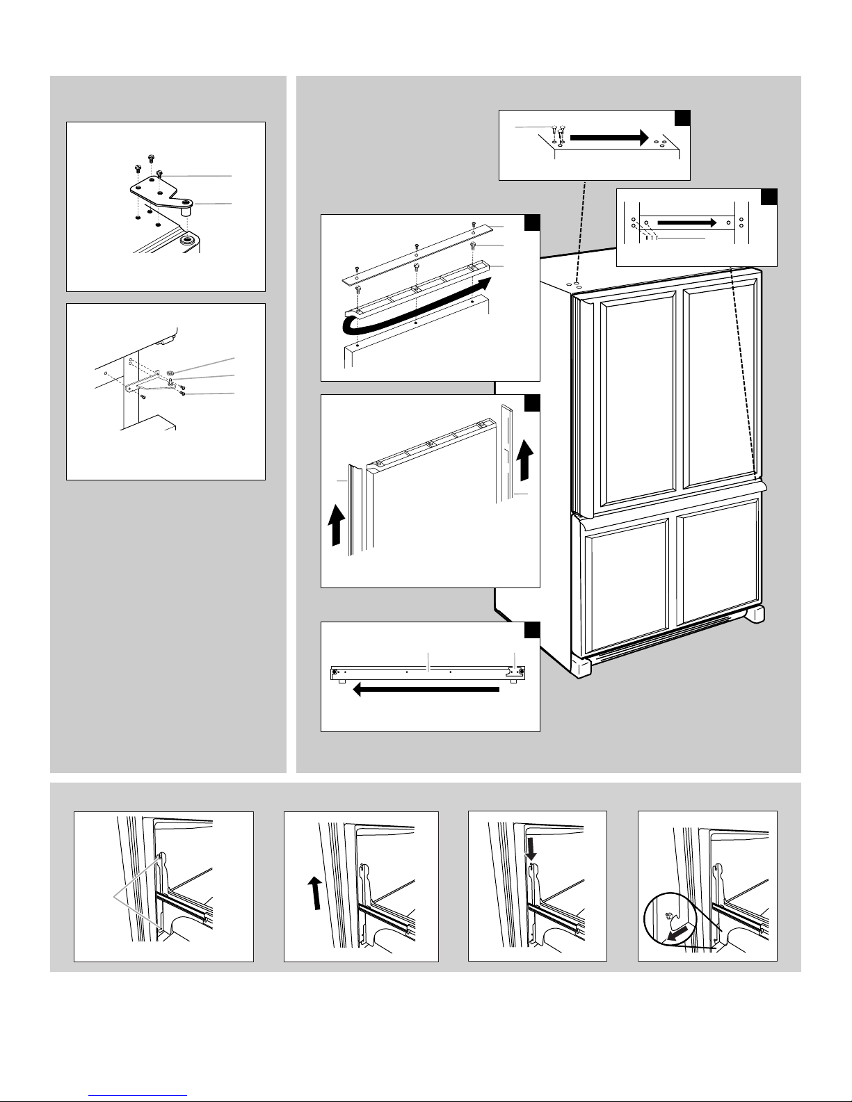
Replace Door and Hinges
Freezer Drawer
IMPORTANT: Two people may be required to remove and replace
the freezer drawer.
Remove Drawer Front
1. Open the freezer drawer to full extension.
2. Loosen the four screws attaching the drawer glides to the
drawer front. See Drawer Front Removal graphic.
NOTE: Loosen screws three to four turns. Keep the screws in
the drawer front.
3. Lift drawer front upward and off the screws. See Drawer Front
Removal graphic.
Replace Drawer Front
1. Slide the drawer glides out of the freezer compartment. Insert
the screws in the top of the drawer front into the slots in the
drawer brackets. See Drawer Front Replacement graphic.
2. Pull the drawer brackets toward you to position the two
screws in the bottom of the drawer front into the brackets.
See Drawer Front Replacement graphic.
3. Completely tighten the four screws.
4. Replace the base grille.
Final Steps
1. Check all holes to make sure that hole plugs and screws are in
place. Reinstall top hinge cover. See Top Hinge Graphic.
WARNING
Electrical Shock Hazard
Plug into a grounded 3 prong outlet.
Do not remove ground prong.
Do not use an adapter.
Do not use an extension cord.
Failure to follow these instructions can result in death,
fire, or electrical shock.
NOTE: When reversing panel series door, use alternate top hinge
shipped with refrigerator.
1. Replace the parts for the bottom hinge as shown in Bottom
Hinge graphic. Tighten screws. Replace the refrigerator door.
NOTE: Provide additional support for the refrigerator door
while the hinges are being moved. Do not depend on the door
gasket magnets to hold the door in place while you are
working.
2. Assemble the parts for the top hinge as shown in the Top
Hinge Graphic. Do not tighten screws completely.
3. Line up the door so that the bottom of the refrigerator door
aligns evenly with the top of the freezer drawer. Tighten all
screws.
6
Downloaded from www.Manualslib.com manuals search engine
2. Plug into a grounded 3 prong outlet.
3. Return all removable door parts to doors and food to
refrigerator.

Architect
®
Series
Door Removal &
Replacement
Top Hinge
A. Hinge Cover Screw
B. Top Hinge Cover
5
/16" Hex-Head Hinge Screws
C.
D. Top Hinge
Bottom Hinge
A. Shim (on some models)
B. Center Hinge
C. Hinge Screws
Door Swing Reversal (optional)
2
A
A
A. Cabinet Hinge Hole Plugs
B
C
D
A
A
B
C
3
/32" Set Screw
A.
Front View
Side View
3
1-2
A
A
A. Hinge Screws
A
1-1
A
A. Door Stop Screws
B. Door Stop
B
5
4
Door Handle
A
A. 3/32" Set Screw
Drawer Front Removal
A
Drawer Front Replacement
Seal Screw
Front
A. Loosen 4 Door Bracket Screws
Downloaded from www.Manualslib.com manuals search engine
7
Panel Series
Door Removal &
Replacement
Top Hinge
A. 5/16" Hex-Head Hinge Screws
B. Top Hinge
Bottom Hinge
A. Shim (on some models)
B. Center Hinge
C. Hinge Screws
Door Swing Reversal (optional)
A
A
B
A. Top Door Cap
1
B.
A
B
C
/4" Hex-Head Screws
C. Top Door Extension
A. Cabinet Hinge Hole Plugs
3
A
B
C
4
A
B
1
2
A
A. Hinge Screws
Drawer Front Removal
A
A. Loosen 4 Door Bracket Screws
A.
Handle Trim
B. Side Door Trim
AB
A. Bottom Door Cap
B. Door Stop
5
Drawer Front Replacement
8
Downloaded from www.Manualslib.com manuals search engine

Adjust the Door
B
C
Depending on your model, your refrigerator may have four
adjustable rollers (Style 1) or a leveler foot screw (Style 2) located
at the base of the refrigerator. If your refrigerator seems unsteady
or you want the door to close more easily, use the instructions
below.
1. Remove the base grille. Grasp the grille firmly and pull it
toward you.
2. Raise or lower the cabinet.
Style 1 - Front and rear leveling
Using a ³⁄₈" hex driver, turn the roller adjustment screw(s) on each
side to raise or lower that side of the refrigerator.
NOTE: Having someone push against the top of the refrigerator
takes some weight off the adjustment screws and rollers. This
makes it easier to turn the screws. It may take several turns of the
roller adjustment screw to adjust the tilt of the refrigerator
Turn the brake foot clockwise until it is firmly against the floor to
keep the refigerator from rolling forward when the freezer drawer
is pulled open.
■ To raise, turn the roller adjustment screw to the right.
■ To lower, turn the roller adjustment screw to the left.
3. Open the door again to make sure that it closes as easily as
you like. If not, tilt the refrigerator slightly more to the rear by
turning both leveling screws clockwise. It may take several
more turns, and you should turn both screws the same
amount.
4. Replace the base grille.
Factory Trim Kit
(on some models)
There may be an occasion when you will need to remove the
factory-installed trim kit, such as moving the refrigerator to a new
home or installing custom-made decorator panels. Please read all
instructions before removing the trim kit and decorator panels.
A
A
B
C
A. Rear roller adjustment screw
B. Front roller adjustment screw
C. Brake foot
Style 2 - Leveling screw
Using a ¹⁄₄" hex driver, turn the leveling screw on each side to raise
or lower that side of the refrigerator.
NOTE: Having someone push against the top of the refrigerator
takes some weight off the leveling screws. This makes it easier to
turn the screws. It may take several turns of the leveling screw to
adjust the tilt of the refrigerator.
■ To raise, turn the leveling screw clockwise.
■ To lower, turn the leveling screw counterclockwise.
A
A. Leveling screw
A. 2
¹⁄₂
" (6.35 cm) Clearance
B. Raised decorator panel
C. Raised drawer panel
Remove the Door Panel
IMPORTANT:
■ Door must be removed from refrigerator before removing
handle.
■ Top trim must be removed from refrigerator before removing
door panel.
1. Remove the refrigerator handle:
■ Using a Phillips screwdriver, remove the top door cap.
■ Tap the bottom edge of refrigerator door handle upward
with a rubber mallet.
■ The handle will slide up approximately ³⁄₄" (19.05 mm) and
release from door.
2. Remove the door panel:
■ Slide out decorator panel and filler board.
■ Store panel and filler board in such a manner as to avoid
scratching.
Replace the Door Panel
1. Replace the refrigerator door panel:
■ Slowly slide the ¹⁄₄" (6.35 mm), maximum thickness,
decorator panel in grooves provided by bottom door cap
and side trim.
■ Slide the filler board into place behind the decorator panel,
if necessary.
2. Attach the handle and trim.
3. Reinstall the refrigerator door.
Downloaded from www.Manualslib.com manuals search engine
9

Remove and Replace Freezer Drawer Panel
NOTE: You do not need to remove the freezer drawer to remove
or replace the decorator panel.
1. Pull the freezer drawer out to access the handle screws.
2. Using a Phillips screwdriver, remove the handle screws and lift
off the handle.
3. Slide the decorator panel and filler board up through handle
opening.
4. Replace the decorator panels by reversing directions.
Dimensions for Routing Handle Side of Raised Door
Panels (End View)
¹⁄₄" (6 mm) max.
Care of Decorator Panels
1. Clean panels with stainless steel cleaner and polish or mild
soap and water with a clean, soft, damp cloth.
2. Rinse panels thoroughly and blot dry using a dry, soft cloth or
chamois.
NOTE: Do not use paper towels or cleaners which contain
solvents such as ammonia. They can damage the surface of
the panels.
Install Custom Wood Panels
If you plan to install custom wood decorator panels, you will need
to create the panels yourself or consult your cabinetmaker or
carpenter. See dimensional drawings for wood panel inserts.
Flat Panels:
You can create a custom flat panel a maximum of ¹⁄₄" (6.35 mm)
thick to replace your decorator panels. Flat wood panels less than
¹⁄₄" (6.35 mm) thick are not recommended.
Raised Panels:
A raised panel design can be created by screwing or gluing wood
panels to ¹⁄₄" (6.35 mm) backing or by using ³⁄₄" (19.05 mm) stock
with routed edges. Allow 2¹⁄₂" (6.35 cm) minimum clearance
between raised edge of panel and handle.
Weight requirements for raised panel inserts:
■ Refrigerator door panel should not exceed 30 lbs (14 kg).
■ Freezer drawer panels should not exceed 15 lbs (7 kg)
combined weight.
Dimensions for Custom Wood Panels
20 cu. ft. Refrigerator door
355/
8"
(90.5 cm)
2¹⁄₂" (6.35 cm)
A
min.
A. Handle
B. Door panel
B
Dimensions for Routing Door Panel (Side View)
¹⁄₄"
(6.35 mm) max.
¹⁄₂"
(1.3 cm)
min.
Center face
detail between
offsets
³⁄₈"
(9.5 mm)
min.
Top
Bottom
¹⁄₄"
(6.35 mm) max.
REFRIGERATOR USE
361/
16"
(91.6 cm)
10
Downloaded from www.Manualslib.com manuals search engine
42"
(106.7 cm)
231/
4"
(59.1 cm)
Using the Controls
Your model may have Electronic Controls or Digital Controls.
IMPORTANT:
■ Wait 24 hours for your refrigerator to cool completely before
adding food. If you add food before the refrigerator has cooled
completely, your food may spoil.
NOTE: Adjusting the Refrigerator and Freezer Controls to a
higher (colder) than recommended setting will not cool the
compartments any faster.
■ The recommended settings should be correct for normal
household refrigerator use. The controls are set correctly
when milk or juice is as cold as you like and when ice cream is
firm.
■ If the temperature is too warm or too cold in the refrigerator or
freezer, first check the air vents to be sure they are not
blocked before adjusting the controls.
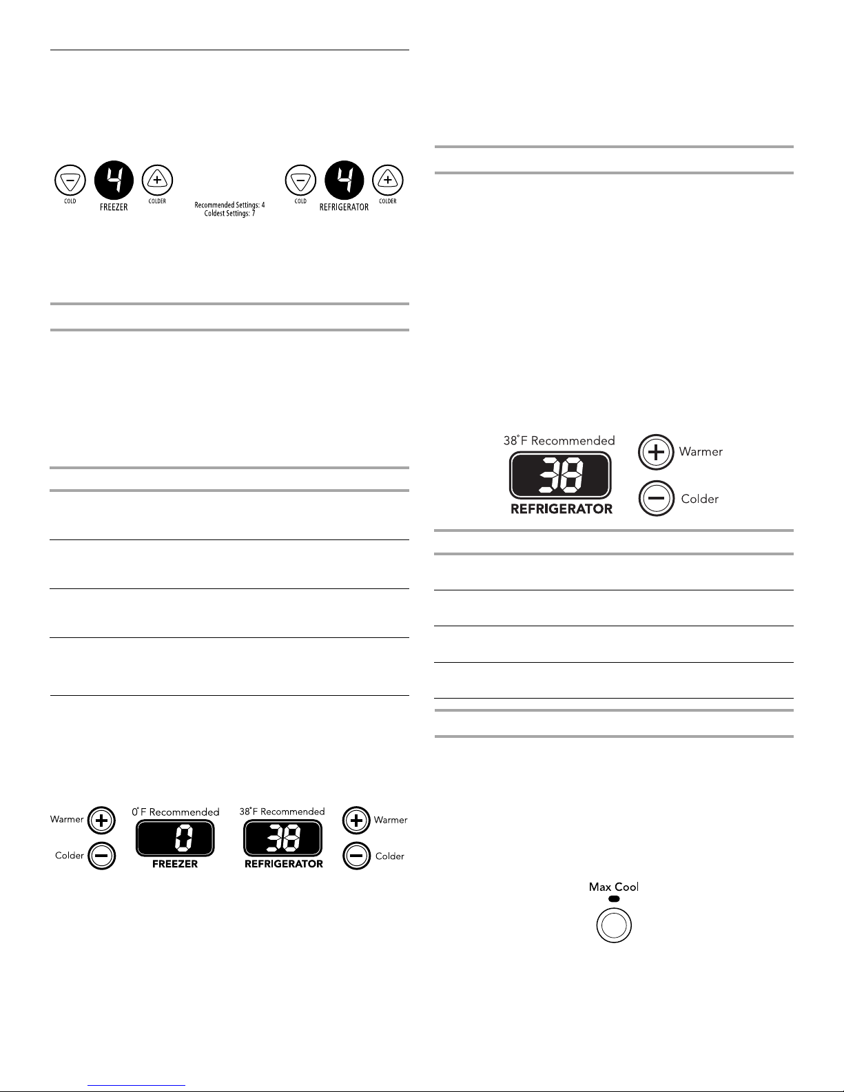
Electronic Controls
For your convenience, your refrigerator and freezer controls are
preset at the factory. When you first install your refrigerator, make
sure the controls are still set to the recommended setting as
shown.
Recommended Setting “4”
To Turn Your Refrigerator Off/On:
■ To turn your refrigerator off, press the freezer down arrow
touch pad until a dash (-) appears in both the refrigerator and
freezer displays. Neither compartment will cool.
Adjusting Electronic Controls
The temperature control range for each compartment is 1 through
7 (coldest).
Press the up or down arrow touch pads to adjust the temperature.
Except when starting the refrigerator, do not adjust either control
more than one setting at a time. Wait 24 hours between
adjustments for the temperature to stabilize.
If you need to adjust the temperature in either the refrigerator or
freezer compartment, use the settings listed in the chart below as
a guide.
CONDITION/REASON: ADJUSTMENT:
To Turn Your Refrigerator Off/On:
■ Press the freezer (+) touch pad repeatedly until “OFF” appears
in the freezer display. Allow a few seconds for the refrigerator
to shut off. Neither compartment will cool.
■ Press either the refrigerator or freezer (-) touch pad to turn on
the refrigerator.
Adjusting Digital Controls
The REFRIGERATOR control adjusts the refrigerator compartment
temperature. The FREEZER control adjusts the freezer
compartment temperature.
If you need to adjust the temperature in either the refrigerator or
freezer compartment, use the settings listed in the chart as a
guide.
To Adjust Set Point Temperatures:
The first touch of the (+) or (-) touch pad displays the current
temperature set point. The display will show the set point for
approximately 3 seconds, and then return to the actual
temperature.
■ Press the (+) or (-) touch pads until the desired temperature
set point is displayed.
NOTE: Except when first turning on the refrigerator, do not
adjust either temperature control more than one setting at a
time. Wait 24 hours between adjustments for the temperature
to stabilize.
REFRIGERATOR too warm Adjust REFRIGERATOR
Control one setting
higher
FREEZER too warm/to little ice Adjust FREEZER
Control one setting
higher
REFRIGERATOR too cold Adjust REFRIGERATOR
Control one setting
lower
FREEZER too cold Adjust FREEZER
Control one setting
lower
Digital Controls
For your convenience, your temperature controls are preset at the
factory. When you first install your refrigerator, make sure the
controls are still set to the recommended set points as shown.
Recommended Settings
IMPORTANT: When the power is on, the temperature display
shows the actual temperature of the compartment.
CONDITION/REASON: ADJUSTMENT:
REFRIGERATOR too warm Adjust REFRIGERATOR
Control 1° lower
FREEZER too warm/too little ice Adjust FREEZER
Control 1° lower
REFRIGERATOR too cold Adjust REFRIGERATOR
Control 1° higher
FREEZER too cold Adjust FREEZER
Control 1° higher
Additional Digital Control Center Features
Max Cool
The max cool feature assists with periods of high refrigerator use,
full grocery loads, or temporarily warm room temperatures.
■ Press the Max Cool touch pad to set the freezer and
refrigerator to the lowest temperature settings. Press the Max
Cool touch pad again to return to the normal refrigerator set
point.
NOTE: The Max Cool feature will automatically shut off in
approximately 12 hours.
Downloaded from www.Manualslib.com manuals search engine
11
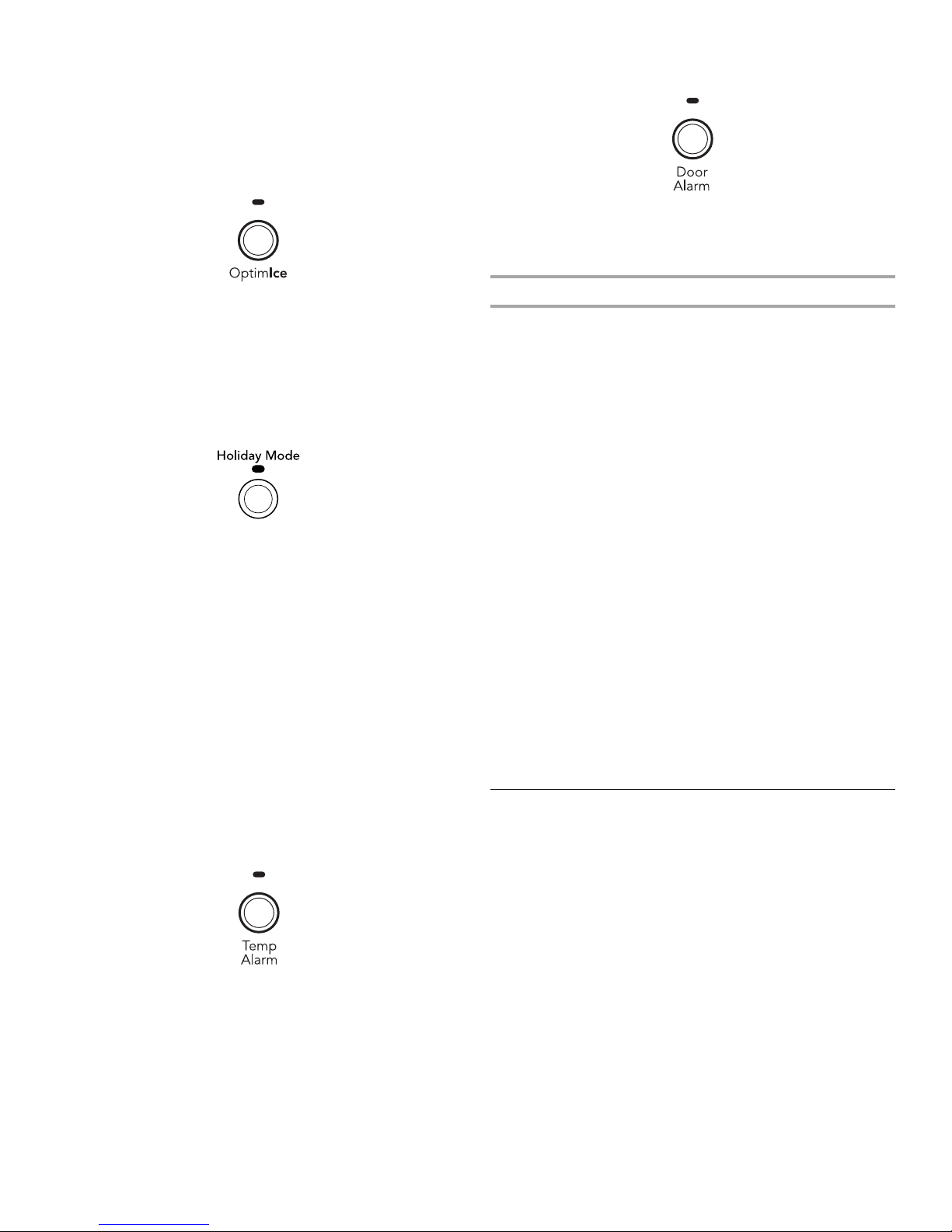
®
OptimIce
Feature
The OptimIce® feature assists with temporary periods of heavy ice
use by increasing ice production.
■ Press the OptimIce
lowest temperature setting. Press the OptimIce
®
feature touch pad to set the freezer to the
®
feature touch
pad again to return to the normal freezer set point.
®
NOTE: The OptimIce
feature will automatically shut off in
approximately 24 hours.
Holiday Mode
In Holiday Mode, the freezer will not automatically defrost as often
to conserve energy.
■ Press the Holiday Mode touch pad until the indicator light is lit
to turn on this feature. Press the Holiday Mode touch pad
again or open the refrigerator door to turn off this feature.
NOTE: The refrigerator door may be opened within 1 hour of
setting Holiday Mode without turning off the feature.
Tem p A la rm
The Temp Alarm feature provides temperature information in the
event of a power outage.
Power outage: During a power outage, if the temperatures in the
refrigerator and freezer compartments exceed normal operating
temperatures, the highest temperature reached will be displayed.
■ Press the Temp Alarm touch pad until the indicator light is lit,
to turn on this feature. Press and hold Temp Alarm for
3 seconds until the indicator light goes off to turn off this
feature.
Temperature alarm: An alarm will sound repeatedly if the freezer
or refrigerator compartment temperatures exceed normal
operating temperatures for an hour or more.
The temperature displays will alternately show the current
temperatures and the highest temperatures the compartments
reached.
■ Press the Temp Alarm touch pad once to stop the audible
alarm and alternating temperature displays. The Temp Alarm
light will continue to flash until the refrigerator returns to the
set temperature.
■ Press the Door Alarm touch pad to turn this feature on or off.
The indicator light will be lit when the Door Alarm feature is on.
Water Filter Status Light and Filter Reset
(on some models)
See “Water Filtration System”
Digital Control User Preferences
The control center allows you to set user preferences, if desired.
Temperature Display (F_C)
This preference allows you to change the temperature display.
F - Temperature in degrees Fahrenheit
C - Temperature in degrees Celsius
Alarm (AL)
This preference allows you to turn off the sound of all alarms.
ON - You will hear the alarm sound.
OFF - You will not hear the alarm sound.
Sabbath Mode (SAB)
IMPORTANT: This preference does not disable interior lights.
ON - All control panel lights will be disabled.
OFF - All control panel lights will be enabled.
NOTE: Press any touch pad on the control panel to restore the
control panel lights.
To Access the User Preferences Menu:
1. Press and hold the Door Alarm touch pad for 3 seconds. The
preference name will appear in the Freezer display and the
preference status (F or C) or (ON or OFF) will appear in the
Refrigerator display.
2. Use the Freezer (+) or (-) touch pads to scroll through the
preference names. When the desired preference name is
displayed, press the Refrigerator (+) or (-) touch pads to
change the preference status.
3. Set your preferences by pressing and holding the Door Alarm
touch pad for 3 seconds, or by shutting the refrigerator
compartment door.
Crisper Humidity Control
You can control the amount of humidity in the moisture-sealed
crisper. Depending on your model, adjust the control to any
setting between FRUIT and VEGETABLES or LOW and HIGH.
FRUIT / LOW (open) for best storage of fruits and vegetables with
skins.
VEGETABLES / HIGH (closed) for best storage of fresh, leafy
vegetables.
Door Alarm
The Door Alarm feature sounds a chime every few seconds when
the refrigerator door has been left open for 5 continuous minutes.
The chime will sound until the door is closed or Door Alarm is
turned off.
12
Downloaded from www.Manualslib.com manuals search engine

Ice Maker
Turning the Ice Maker On/Off
To turn the ice maker ON, simply lower the wire shutoff arm.
To manually turn the ice maker OFF, lift the wire shutoff arm to the
OFF (arm up) position and listen for the click.
NOTE: Your ice maker has an automatic shutoff. As ice is made,
the ice cubes will fill the ice storage bin and the ice cubes will
raise the wire shutoff arm to the OFF (arm up) position. Do not
force the wire shutoff arm up or down.
Ice Production Rate
Dispensing Water
1. Hold a container under the dispenser while pressing the
button.
2. Release the button to stop dispensing.
■ The ice maker should produce a complete batch of ice
approximately every 3 hours.
■ To increase ice production, lower the freezer and refrigerator
temperature. See “Using the Controls.” Wait 24 hours
between adjustments.
Remember
■ Allow 24 hours to produce the first batch of ice. Discard the
first three batches of ice produced.
■ The quality of your ice will be only as good as the quality of the
water supplied to your ice maker. Avoid connecting the ice
maker to a softened water supply. Water softener chemicals
(such as salt) can damage parts of the ice maker and lead to
poor quality ice. If a softened water supply cannot be avoided,
make sure the water softener is operating properly and is well
maintained.
■ Do not store anything on top of the ice maker or in the ice
storage bin.
Water Dispenser
(on some models)
IMPORTANT:
■ After connecting the refrigerator to a water source, flush the
water system. Press the button on the dispenser for
5 seconds, then release it for 5 seconds. Repeat until water
begins to flow. Once water begins to flow, continue
depressing and releasing the dispenser button (5 seconds on,
5 seconds off) for an additional 2 minutes. This will flush air
from the filter and water dispensing system. Additional
flushing may be required in some households. As air is cleared
from the system, water may spurt out of the dispenser.
NOTE: After five minutes of continuous dispensing, the
dispenser will stop dispensing water to avoid flooding. To
continue dispensing, press the dispenser button again.
■ Allow 24 hours for the refrigerator to cool down and chill
water. Dispense enough water every week to maintain a fresh
supply.
Water Filtration System
The water filter is located in the upper right-hand corner of the
refrigerator compartment.
Do not use with water that is microbiologically unsafe or
of unknown quality without adequate disinfection before
or after the system. Systems certified for cyst reduction
may be used on disinfected waters that may contain
filterable cysts.
Water Filter Status Light
The water filter status light will help you know when to change the
water filter. When the yellow (Order) light is on, it is almost time to
change the water filter. When the red (Replace) light is on, a new
water filter should be installed. See “Water Filtration System.”
After replacing the water filter, press and hold FILTER RESET for
3 seconds until the Order or Replace light turns off.
Replacing the Water Filter
To purchase a replacement water filter, model 67003523 Part
Number 4396395, contact your dealer or call 1-800-442-9991
U.S.A. or 1-800-807-6777 Canada.
IMPORTANT: Air trapped in the water system may cause water
and filter to eject. Always dispense water for at least 2 minutes
before removing the filter or blue bypass cap.
1. Turn filter counterclockwise to remove.
2. Remove sealing label from replacement filter and insert the
filter end into the filter head.
3. Turn the filter clockwise until it stops. Snap the filter cover
closed.
NOTE: The dispenser feature may be used without a water filter
installed. Your water will not be filtered. If this option is chosen,
replace the filter with the blue bypass cap.
Downloaded from www.Manualslib.com manuals search engine
13
 Loading...