


KitchenAid KBFN502EBS01, KBFN402EPA02, KBFN402EPA01, KBFN506ESS00, KBFN506ESS01 Installation Guide
...BOTTOM-MOUNT
BUILT-IN REFRIGERATOR
Installation Guide
IMPORTANT: READ AND SAVE THESE INSTRUCTIONS. INSTALLATION REQUIRES 2 OR MORE PEOPLE.
REFRIGERADOR EMPOTRADO CON CONGELADOR EN LA PARTE INFERIOR
Guía de instalación
IMPORTANTE: LEA Y GUARDE ESTAS INSTRUCCIONES. LA INSTALACIÓN REQUIERE DE 2 O MÁS PERSONAS.
RÉFRIGÉRATEUR ENCASTRÉ AVEC CONGÉLATEUR EN DESSOUS
Guide d’installation
IMPORTANT : LIRE ET CONSERVER CES INSTRUCTIONS. L’INSTALLATION NÉCESSITE L’INTERVENTION DE 2 PERSONNES OU PLUS.
Table of Contents/Índice/Table des matières ................................................................. |
2 |
W10721177C

TABLE OF CONTENTS
REFRIGERATOR SAFETY ............................................................. |
3 |
MODELS.......................................................................................... |
4 |
INSTALLATION REQUIREMENTS ................................................ |
6 |
Tools and Parts ............................................................................ |
6 |
Location Requirements................................................................ |
6 |
Electrical Requirements ............................................................... |
7 |
Water Supply Requirements ........................................................ |
7 |
Tipping Radius ............................................................................. |
8 |
Product Dimensions..................................................................... |
8 |
Door Swing Dimensions............................................................. |
10 |
Overlay Series Custom Panels .................................................. |
11 |
Custom Overlay Panel Dimensions ........................................... |
12 |
Stainless Steel and Overlay Series Both 36" and 42" models |
|
have the same cabinet side trim................................................ |
15 |
INSTALLATION INSTRUCTIONS ................................................ |
16 |
Unpack the Refrigerator............................................................. |
16 |
Reduce Tipping Radius.............................................................. |
16 |
Move the Refrigerator into House.............................................. |
16 |
Install Anti-Tip Boards................................................................ |
17 |
Connect the Water Supply......................................................... |
17 |
Plug in Refrigerator..................................................................... |
19 |
Move Refrigerator to Final Location........................................... |
19 |
Level and Align Refrigerator....................................................... |
20 |
Install Overlay Custom Panels ................................................... |
20 |
Adjust Door(s)............................................................................. |
22 |
Install Side Panel ........................................................................ |
24 |
Install Base Grille........................................................................ |
24 |
Complete Installation.................................................................. |
25 |
ÍNDICE
SEGURIDAD DEL REFRIGERADOR........................................... |
26 |
MODELOS..................................................................................... |
27 |
REQUISITOS DE INSTALACIÓN................................................. |
29 |
Herramientas y piezas................................................................ |
29 |
Requisitos de ubicación............................................................. |
29 |
Requisitos eléctricos.................................................................. |
30 |
Requisitos del suministro de agua............................................. |
30 |
Arco de vuelco ........................................................................... |
31 |
Medidas del producto................................................................ |
31 |
Medidas de oscilación de la puerta........................................... |
33 |
Paneles a la medida de la serie de paneles recubiertos ........... |
34 |
Dimensiones del panel recubierto a la medida ......................... |
35 |
Paneles y juegos de fábrica para las series Stainless Steel |
|
y de paneles recubiertos (modelos de 36" [91,4 cm]) .............. |
38 |
INSTRUCCIONES DE INSTALACIÓN......................................... |
39 |
Desempaque el refrigerador ...................................................... |
39 |
Cómo reducir el arco de vuelco (si es necesario)...................... |
39 |
Cómo hacer entrar el refrigerador en la casa ............................ |
39 |
Cómo instalar los tableros antivuelco........................................ |
40 |
Conexión del suministro de agua .............................................. |
40 |
Cómo enchufar el refrigerador ................................................... |
43 |
Cómo mover el refrigerador a su ubicación final....................... |
43 |
Nivelación y alineamiento del refrigerador................................. |
43 |
Cómo instalar los paneles a la medida para la serie |
|
de paneles recubiertos............................................................... |
44 |
Cómo ajustar la(s) puerta(s) ....................................................... |
45 |
Cómo instalar el panel lateral..................................................... |
47 |
Cómo instalar la rejilla de la base .............................................. |
47 |
Cómo terminar la instalación ..................................................... |
48 |
TABLE DES MATIÈRES
SÉCURITÉ DU RÉFRIGÉRATEUR .............................................. |
49 |
MODÈLES ..................................................................................... |
50 |
EXIGENCES D’INSTALLATION................................................... |
52 |
Outillage et pièces...................................................................... |
52 |
Exigences d’emplacement......................................................... |
52 |
Spécifications électriques .......................................................... |
54 |
Spécifications de l’alimentation en eau ..................................... |
54 |
Rayon de basculement .............................................................. |
55 |
Dimensions du produit............................................................... |
55 |
Dimensions pour le pivotement des portes............................... |
56 |
Panneaux personnalisés de la série Panneaux décoratifs........ |
57 |
Panneaux personnalisés décoratifs—Dimensions .................... |
58 |
Ensembles de panneaux d’origine de la série Stainless |
|
Steelet Panneaux décoratifs (modèles de 36" [91,4 cm])........ |
61 |
INSTRUCTIONS D’INSTALLATION............................................. |
62 |
Déballage du réfrigérateur.......................................................... |
62 |
Réduction du rayon de basculement......................................... |
62 |
Faire entrer le réfrigérateur dans le domicile ............................. |
62 |
Installation de planches antibasculement.................................. |
63 |
Raccordement à l’alimentation en eau ...................................... |
63 |
Branchement du réfrigérateur .................................................... |
66 |
Déplacement du réfrigérateur à l'emplacement final................. |
66 |
Réglage de l’aplomb et alignement du réfrigérateur ................. |
66 |
Installation des panneaux personnalisés de la série |
|
Panneaux décoratifs................................................................... |
67 |
Ajustement de la (des) porte(s)................................................... |
68 |
Installation du panneau latéral ................................................... |
70 |
Installation de la grille de la base ............................................... |
71 |
Achever l’installation .................................................................. |
71 |
2

REFRIGERATOR SAFETY
Your safety and the safety of others are very important.
We have provided many important safety messages in this manual and on your appliance. Always read and obey all safety messages.
This is the safety alert symbol.
This symbol alerts you to potential hazards that can kill or hurt you and others.
All safety messages will follow the safety alert symbol and either the word “DANGER” or “WARNING.” These words mean:
 DANGER
 WARNING
You can be killed or seriously injured if you don't immediately follow instructions.
You can be killed or seriously injured if you don't follow instructions.
All safety messages will tell you what the potential hazard is, tell you how to reduce the chance of injury, and tell you what can happen if the instructions are not followed.
WARNING
Refrigerator is top |
easily when not |
completely installed. |
|
Keep doors taped closed until refrigerator is completely installed.
Use two or more people to move and install refrigerator.
Failure to do so can result in death or serious injury.
3
MODELS
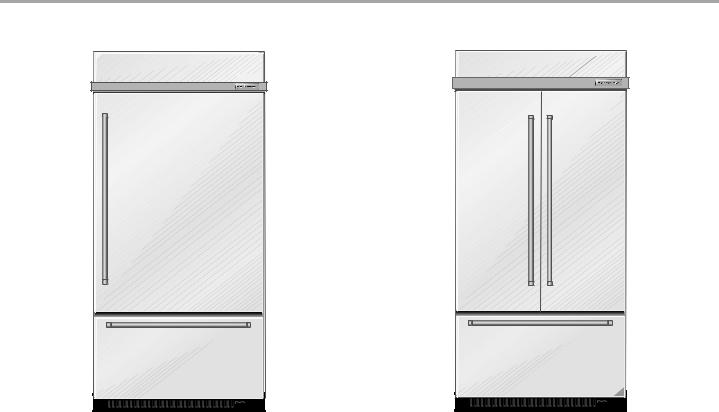
Stainless Steel Series (36" [91.4 cm] Models)
Features wraparound styling that complements the contoured door handles. This series provides a warm commercial-looking built-in refrigerator.
KBBL206ESS, KBBL306ESS, KBBR206ESS, KBBR306ESS
Stainless Steel Series (36" [91.4 cm] Models)
Features wraparound styling that complements the contoured door handles. This series provides a warm commercial-looking built-in refrigerator.
KBFN406ESS, KBFN506ESS
Black Stainless Steel Series (36" [91.4 cm] Models)
KBFN506EBS
4

Overlay Series (36" [91.4 cm] Models)
Features factory-installed, overlay style trim, to provide a “frameless” look. This series requires the installation of custom panels, handles, and standoffs.
KBBL206EPA, KBBL306EPA, KBBR206EPA, KBBR306EPA
Stainless Steel Series (42" [106.7 cm] Models)
Features wraparound styling that complements the contoured door handles. This series provides a warm commercial-looking built-in refrigerator.
KBFN402ESS, KBFN502ESS
Black Stainless Steel Series (42" [106.7 cm] Models)
KBFN502EBS
Overlay Series (36" [91.4 cm] Models)
Features factory-installed, overlay style trim, to provide a “frameless” look. This series requires the installation of custom panels, handles, and standoffs.
KBFN406EPA, KBFN506EPA
Overlay Series (42" [106.7 cm] Models)
Features factory-installed, overlay style trim, to provide a “frameless” look. This series requires the installation of custom panels, handles, and standoffs.
KBFN402EPA, KBFN502EPA
5
INSTALLATION REQUIREMENTS
Tools and Parts
IMPORTANT:
■Installer: Leave Installation Instructions with the homeowner.
■Homeowner: Keep Installation Instructions for future reference. Save these Installation Instructions for the local electrical inspector’s use.
Tools Needed
Gather the required tools and parts before starting installation. Read and follow the instructions provided with any tools listed here.
■ |
Cordless drill |
■ |
Torx®† T15 and T27 screwdrivers |
■ |
Drill bits |
■ |
¹¹⁄ " nut driver |
■ |
Adjustable |
■ |
³⁄ ", ¹⁄ ", and ¹⁄ " open-end |
|
wrenches (2) |
|
wrenches |
■ |
Phillips screwdriver |
■ |
⁄ " hex key |
■ |
Small level |
■ |
¹⁄ " and ⁄ " socket drivers |
■ |
Appliance dolly |
■ |
Tape measure |
|
|
■ |
Utility knife |
Parts Needed
■#8 x 3" (7.6 cm) wood screws (longer screws may be needed) (6)
■2" x 4" x 32" (5 cm x 10 cm x 81 cm) wood board(s) (1 or 2)
■Make custom panels or consult a qualified cabinetmaker or carpenter to make the panels.
Overlay Series: Make custom panels, or consult a qualified cabinetmaker or carpenter to make the panels. See “Installation Requirements” for more information.
Stainless Series and Black Stainless Series are shipped complete.
■If you are connecting the water line directly to copper tubing and not to a shutoff valve, you need a ferrule, a union, and a ¹⁄ " compression fitting.
Location Requirements
The refrigerator can be recessed in an opening between cabinets or installed at the end of a cabinet run using a side panel to enclose the refrigerator.
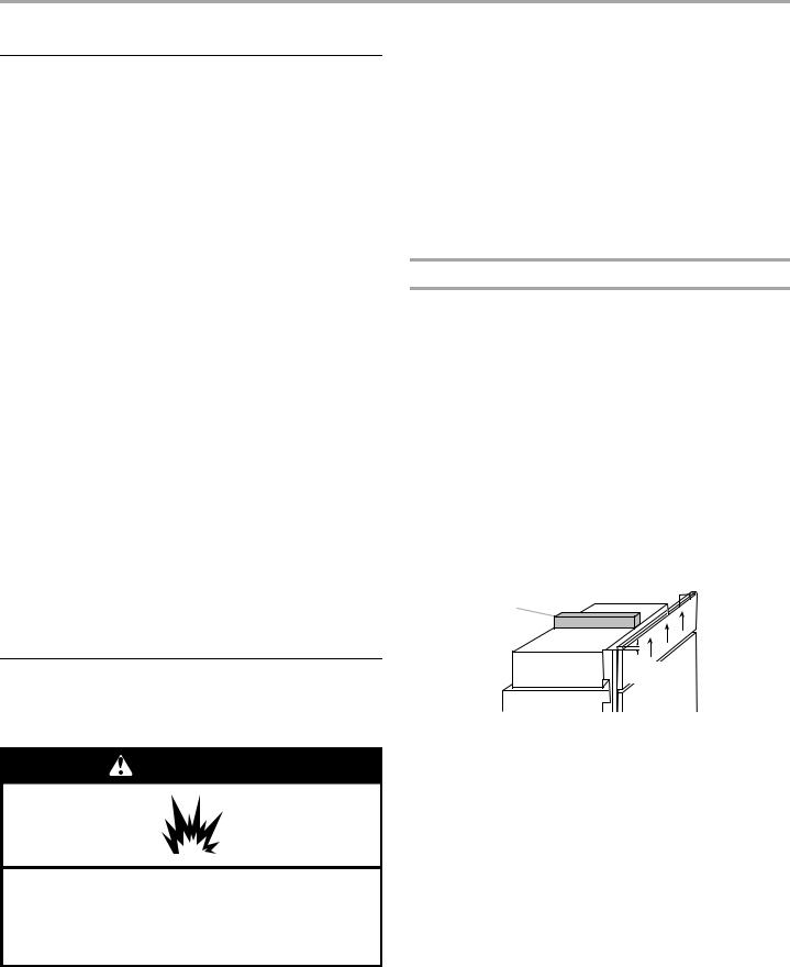
WARNING
Explosion Hazard
Keep flammable materials and vapors, such as gasoline, away from refrigerator.
Failure to do so can result in death, explosion, or fire.
IMPORTANT:
■Observe all governing codes and ordinances.
■It is recommended that you do not install the refrigerator near an oven, radiator, or other heat source.
■Do not install in a location where the temperature will fall below 55°F (13°C).
■Floor must support the refrigerator weight, more than 600 lbs (272 kg), door panels and contents of the refrigerator.
■Ceiling height must allow for side tipping radius. See “Tipping Radius.”
■Location should permit door to open fully. See “Door Swing Dimensions.”
■Location must permit top grille removal. See “Opening Dimensions.”
Opening Dimensions
■To avoid tipping during use, the solid soffit must be within 1" (2.5 cm) maximum above the refrigerator. If the solid soffit is higher than 1" (2.5 cm) or one is not available, then the refrigerator must be braced.
If anti-tip boards are needed, they must be installed to the rear wall studs so that the bottom of the anti-tip board is 84" (213.4 cm) from the floor. See “Install Anti-Tip Boards” for more information.
NOTES:
■A clearance of ¹⁄ " (1.3 cm) must be maintained above the top grille in order for the top grille to be removed.
■Do not remove the foam gasket on top of the compressor cover unless removal is necessary to fit the unit under a soffit. Removal of the gasket will cause loss in cooling efficiency.
■If installing under a solid soffit, after, installation raise the leveling legs so that the gasket is pressed snugly against the soffit.
A
B 
¹⁄"
(1,3 cm)
A.Gasket
B.Compressor cover
■A grounded 3 prong electrical outlet should be placed within 4" (10.2 cm) of the right side cabinets or end panel. See “Electrical Requirements” for additional information.
†®TORX is a registered trademark of Acument Intellectual Properties, LLC.
6

■The water shutoff should be located in the base cabinet on
either side of the refrigerator or some other easily accessible |
Electrical Requirements |
|
|
|
|
||
area. If the water shutoff valve is not in the cabinets, the |
|
|
|
plumbing for the water line can come through the floor or |
|
|
|
|
WARNING |
|
|
the back wall. See “Water Supply Requirements” for more |
|
||
|
|
||
specific information. |
|
|
|
|
|
80" - 90" |
|
Electrical Shock Hazard |
|||
|
|
(203-229 cm) |
B |
Plug into a grounded 3 prong outlet. |
|
||
|
|
|
|
||||
|
|
|
Dimension |
Do not remove ground prong. |
|
||
|
|
|
|
|
|||
|
|
|
|
Do not use an adapter. |
|
|
|
|
|
|
|
Do not use an extension cord. |
|
||
|
83¹⁄ " (212.1 cm) min. |
|
Failure to follow these instructions can result in death, |
||||
|
|
fire, or electrical shock. |
|
|
|||
|
84³⁄ " (215 cm) max. |
|
|
|
|||
|
to bottom of solid soffit |
|
|
|
|
||
|
|
|
|
Before you move your refrigerator into its final location, it is |
|||
|
|
|
|
important to make sure you have the proper electrical |
|||
|
|
|
|
connection. |
|
|
|
|
|
|
77" |
Recommended Grounding Method |
|
||
|
|
|
(196 cm) |
A 115 volt, 60 Hz., AC only, 15or 20-amp fused, grounded |
|||
|
|
|
|
||||
|
|
|
|
electrical supply is required. It is recommended that a separate |
|||
|
|
A |
|
circuit serving only your refrigerator be provided. Use an outlet |
|||
|
|
|
that cannot be turned off by a switch. Do not use an |
||||
|
|
Width |
|
||||
|
|
|
extension cord. |
|
|
||
|
|
(see chart following) |
|
|
|
||
|
|
|
|
IMPORTANT: If this product is connected to a GFCI (Ground |
|||
|
|
|
|
Fault Circuit Interrupter) protected outlet, nuisance tripping of the |
|||
|
|
|
6" |
power supply may occur, resulting in loss of cooling. Food quality |
|||
|
|
|
(15.2 cm) |
and flavor may be affected. If nuisance tripping has occurred, |
|||
|
|
|
|
and if the condition of the food appears poor, dispose of it. |
|||
|
|
|
|
NOTE: Before performing any type of installation or cleaning, |
|||
|
|
|
|
remove the top grille and turn the master power switch to OFF |
|||
|
|
|
|
or disconnect power at the circuit breaker box. |
|||
|
|
|
|
When you are finished, turn ON the master power switch or |
|||
|
|
|
|
reconnect power at the circuit breaker box. Then reset the control |
|||
|
|
1" |
|
to the desired setting. |
|
|
|
|
|
|
|
|
|
||
|
6" |
(2.54 cm) |
6" |
Water Supply Requirements |
|||
|
|
24" |
(15.2 cm) |
||||
|
(15.2 cm) |
|
|
|
|||
|
|
(60.96 cm) min. |
|
■ All installations must meet local plumbing code requirements. |
|||
|
|
|
|
■ The water shutoff should be located in the base cabinet on |
|||
|
|
Width A |
Dimension B |
either side of the refrigerator or some other easily accessible |
|||
|
|
area. The right-hand side is recommended. The access hole |
|||||
Model |
(as shown above) |
(as shown above) |
|||||
through the cabinet must be within ¹⁄ " (1.3 cm) of the rear wall. |
|||||||
|
|
|
|
||||
36" |
35¹⁄ " to 35³⁄ " |
4" (10.2 cm) |
NOTE: If the water shutoff valve is in the back wall behind the |
||||
|
(90.2 cm to 90.8 cm) |
|
refrigerator, it must be at an angle so that the tube is not |
||||
42" |
41¹⁄ " to 41³⁄ " |
7¹⁄ " (19 cm) |
kinked when the refrigerator is pushed into its final location. |
||||
|
|
|
|||||
|
(105.4 cm to 106 cm) |
|
|
|
|
||
NOTE: Flooring under refrigerator must be at same level as the |
|
|
|
||||
room. |
|
|
|
|
|
6" |
|
|
|
|
|
|
|
(15.2 cm) |
|
|
|
|
|
6" |
1" |
6" |
|
|
|
|
|
(2.54 cm) |
|||
|
|
|
|
2 cm) |
|
(15.2 cm) |
|
|
|
|
|
24" |
|
|
|
|
|
|
|
(60.96 cm) min. |
|
||
7
■If the water shutoff valve is not in the cabinets, the plumbing for the water line can come through the floor. A ¹⁄ " (12.7 mm) hole for plumbing should be drilled at least 6" (15.2 cm) from the right-hand or left-hand side cabinet or panel. On the floor, the hole should be no more than 1" (2.54 cm) away from the back wall. See “Connect the Water Supply.”
■If additional tubing is needed, use copper tubing and check for leaks. Install the copper tubing only in areas where the household temperatures will remain above freezing.
■Do not use a piercing-type or ³⁄ " (4.76 mm) saddle valve which reduces water flow and clogs more easily.
NOTE: Your refrigerator dealer has a kit available with a
¹⁄ " (6.35 mm) saddle-type shutoff valve, a union, and copper tubing. Before purchasing, make sure a saddle-type valve complies with your local plumbing codes.
Water Pressure
A cold water supply with water pressure between 30 and 120 psi (207 and 827 kPa) is required to operate the water dispenser and ice maker. If you have questions about your water pressure, call a licensed, qualified plumber.
Reverse Osmosis Water Supply
IMPORTANT: The pressure of the water supply coming out of a reverse osmosis system going to the water inlet valve of the refrigerator needs to be between 30 and 120 psi (207 and
827 kPa).
If a reverse osmosis water filtration system is connected to your cold water supply, the water pressure to the reverse osmosis system needs to be a minimum of 40 to 60 psi (276 to 414 kPa).
If the water pressure to the reverse osmosis system is less than 40 to 60 psi (276 to 414 kPa):
■Check to see whether the sediment filter in the reverse osmosis system is blocked. Replace the filter if necessary.
■Allow the storage tank on the reverse osmosis system to refill after heavy usage.
■If your refrigerator has a water filter cartridge, it may further reduce the water pressure when used in conjunction with a reverse osmosis system. Remove the water filter cartridge.
If you have questions about your water pressure, call a licensed, qualified plumber.
Tipping Radius
Be sure there is adequate ceiling height to stand the refrigerator upright when it is moved into place.
■The dolly wheel height must be added to the tipping radius when a dolly is used.
■If needed, the tipping radius can be reduced. See “Reduce Tipping Radius.”
Side Tipping Radius (36" [91.4 cm] Models)
A 
90¹⁄"
(229.9 cm)
A. Tip this side only.
Side Tipping Radius (42" [106.7 cm] Models)
A 
93" (236.2 cm)
A. Tip this side only.
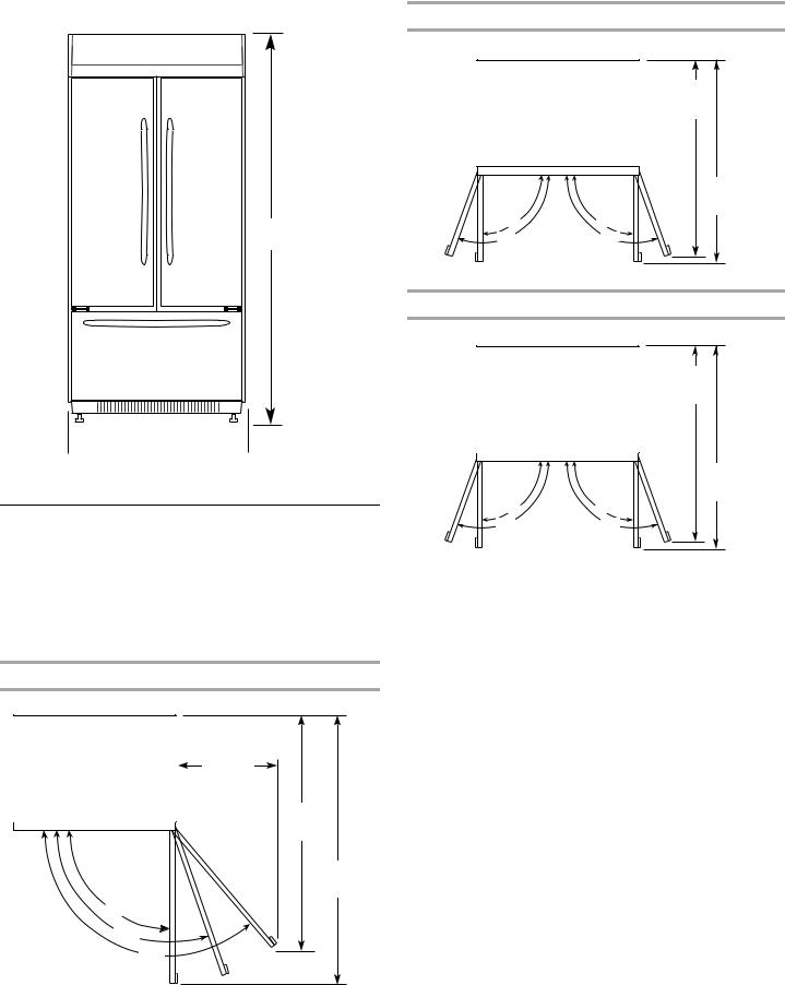
Product Dimensions
Side View
■The depth from the front of the top grille to the back of the refrigerator cabinet is 25³⁄ " (64.5 cm).
■The power cord is 84" (213 cm) long.
8
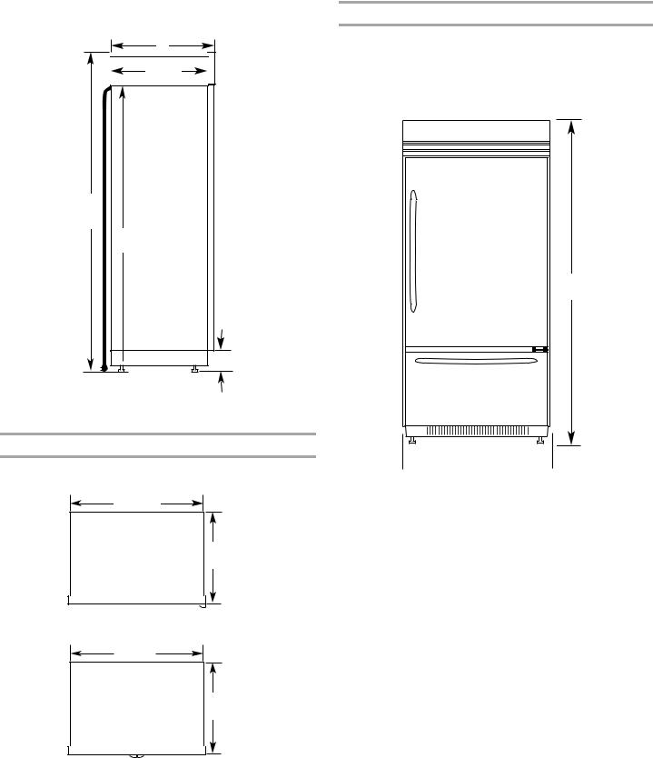
■Height dimensions are shown with leveling legs extended ¹⁄ " (3 mm) below the rollers.
A
23¹⁄ "
(59.7 cm)
*83³⁄ "
(211.8 cm)
84" (213.4 cm) Power Cord
 *3¹⁄ " (8.9 cm)
*When leveling legs are fully extended to 1¹⁄ " (3.2 cm) below rollers, add 1¹⁄ " (2.9 cm) to the height dimensions.
Top View
36" (91.4 cm) Models
35¹⁄ "
(89.5 cm)
25³⁄ "
(64.5 cm)
42" (106.7 cm) Models
41¹⁄ "
(105 cm)
25³⁄ "
(64.5 cm)
Front View
■Width dimensions were measured from trim edge to trim edge.
■Height dimensions are shown with leveling legs extended ¹⁄ " (3 mm) below the rollers.
36" (91.4 cm) Models
*83³⁄ "
(211.8 cm)
 36¹¹⁄32" (92.3 cm)
*When leveling legs are fully extended to 1¹⁄ " (3.2 cm) below rollers, add 1¹⁄ " (2.9 cm) to the height dimensions.
9
42" (106.7 cm) Models
36" (91.4 cm) French Door Models
*83³⁄ "
(211.8 cm)
 42¹¹⁄32" (107.5 cm)
*When leveling legs are fully extended to 1¹⁄ " (3.2 cm) below rollers, add 1¹⁄ " (2.9 cm) to the height dimensions.
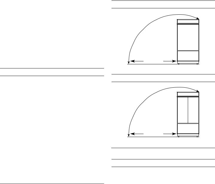
Door Swing Dimensions
The location must permit the door to open to a minimum of 90°. Allow 5" (12.7 cm) minimum space between the side of the refrigerator and a corner wall.
NOTE: The required thickness for all panels is ³⁄ " (1.91 cm). More clearance may be required if you are using overlay panels or custom handles.
To adjust the door swing, see “Adjust Door Swing.”
36" (91.4 cm) Single Door Models
23" (58 cm) max.
51" (130 cm)
59" (150 cm)
90˚
110˚
130˚
39³⁄ "
(101 cm)
41" (104 cm)
90˚ |
90˚ |
110˚ |
110˚ |
42" (106.7 cm) French Door Models
42³⁄ "
(108.6 cm)
44¹⁄ "
(112.3 cm)
90˚ |
90˚ |
110˚ |
110˚ |
10
Overlay Series Custom Panels
Custom overlay panels allow you to blend the exterior of your refrigerator into the overall kitchen décor and to use custom handles for additional design flexibility.
The custom panels must have backer panels attached in order to mount them to the refrigerator. It is most common to work with three panels, as shown in the following graphic: a decorative overlay panel, a ¹/ " (3.18 mm) spacer panel or spacer strips and a ¹/ " (6.35 mm) backer panel.
Overlay Panel |
|
Spacer Panel |
|
|
|
||
⁄ " to ³⁄ " |
|
Backer Panel |
|
|
¹⁄ " |
||
(15.88 to |
|
||
¹⁄ " |
(6.35 mm) |
||
19.05 mm) |
|||
(3.18 mm) |
|||
|
|||
Spacer Panel |
¹⁄ " |
(3.18 mm) |
Overlay Panel |
Backer Panel |
1" minimum |
(2.54 cm) |
Door/Grille Trim |
Offset Dimension |
In some cases, your cabinet manufacturer may choose to work with one panel routed for the different dimensions. Follow these panel dimension and placement instructions to be sure that the custom overlay panels will fit properly.
IMPORTANT:
■For 36" (91.4 cm) single-door models, the refrigerator door overlay panel cannot exceed 50 lbs (23 kg) and the freezer drawer overlay panel cannot exceed 20 lbs (9.1 kg).
■For 36" (91.4 cm) and 42" (106.7 cm) French-door models, the refrigerator door overlay panel cannot exceed 30 lbs (13.5 kg) and the freezer drawer overlay panel cannot exceed 25 lbs (11.4 kg).
■The weight of the top grille overlay panel cannot exceed 10 lbs (4.5 kg) for both models.
To minimize panel weight, you may use 2" (5.08 cm) spacer strips around the perimeter in place of full-sheet solid spacer panels. The spacer strips must be set in at least 1" (2.54 cm) from the top, bottom and side edges of the backer panel. If you use spacer strips, it is also recommended that you use two 2" (5.08 cm) strips horizontally centered for added support.
11
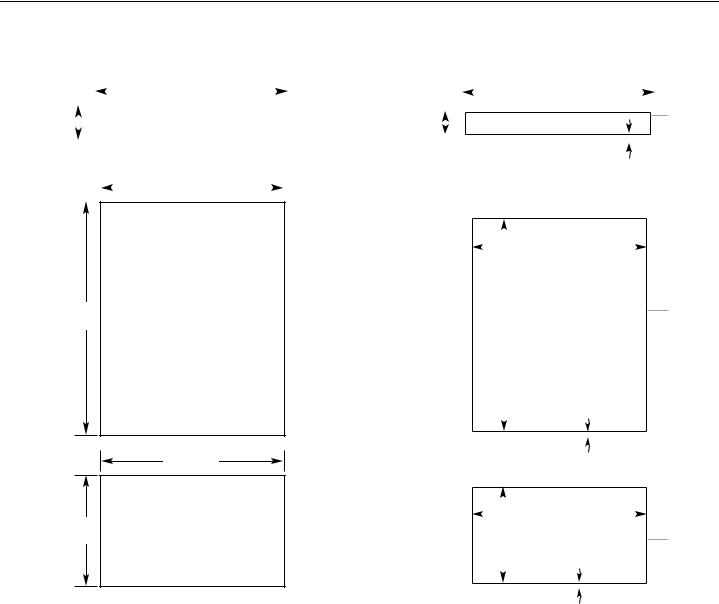
Custom Overlay Panel Dimensions
Custom Overlay Panels
(36" [91.4 cm] Single Door Models)
|
|
|
|
|
|
|
|
|
|
|
34³⁄ " |
|
|
|
||
|
|
|
|
|
|
|
|
|
|
|
(88.27 cm) |
|
|
|
|
|
|
|
|
|
|
|
|
|
|
|
|
|
|
|
|
|
|
7¹⁄ " |
|
|
|
|
|
|
TOP GRILLE PANEL |
|||||||||
|
|
|
|
|||||||||||||
(18.42 cm) |
|
|
|
|
|
|
Maximum Weight: 10 lbs (4.5 kg) |
|||||||||
|
|
|
|
|||||||||||||
|
|
|
|
|
|
|
|
|
|
|
|
|
|
|
|
|
|
|
|
|
|
|
|
|
|
|
|
34³⁄ " |
|
|
|||
|
|
|
|
|
|
|
|
|
|
|
|
|
||||
|
|
|
|
|
|
|
|
|
|
|
(88.27 cm) |
|
|
|
||
|
|
|
|
|
|
|
|
|
|
|
|
|
|
|
|
|
51 |
¹⁄ " |
REFRIGERATOR DOOR PANEL |
(129.86 cm) |
Maximum Weight: 50 lbs (23 kg) |
|
34³⁄ "
(88.27 cm)
20³⁄ " FREEZER DOOR PANEL
(52.71 cm) Maximum Weight: 20 lbs (9.1 kg)
|
|
|
|
|
Custom Backer Panels |
|
|
|
||||
|
|
(36" [91.4 cm] Single Door Models) |
||||||||||
|
|
|
|
|
|
|
33³⁄ " |
|
|
|
|
Center |
|
|
|
|
|
|
|
|
|
|
|
||
|
|
|
|
|
|
|
(85.73 cm) |
|
|
|
|
|
|
|
|
|
|
|
|
|
|
|
|
Backer |
|
|
|
|
|
|
|
|
|
|
|
|
|
|
6³⁄ " |
|
|
|
|
|
|
|
|
|
|
|
Panel |
(15.72 cm) |
|
|
|
|
|
|
|
|
|
|
left to |
|
|
|
|
|
|
|
|
|
|
|
|||
|
|
|
|
|
|
|
|
|
|
|
|
right |
|
|
|
|
|
|
|
|
|
|
|
|
|
|
|
|
|
|
|
|
|
|
|
Bottom Offset |
||
|
|
|
|
|
|
|
|
|
|
³⁄ " (9.5 mm) |
||
|
|
|
34¹⁄ " |
|
|
|
|
|
|
|
|
||
|
|
|
(87.00 cm) |
|
|
Center |
|
|
|
|
|
|
|
|
49¹⁄ " |
|
|
|
||
(124.78 cm) |
|
|
|
Backer |
||
|
|
|
|
|
|
Panel |
|
|
|
|
|
|
|
|
|
|
|
|
|
left to |
|
|
|
|
|
|
right |
|
|
|
|
|
|
|
|
|
|
|
|
|
|
|
|
|
|
Bottom Offset |
||
|
|
|
|
⁄ " (11.1 mm) |
||
|
|
|
|
|
|
|
|
|
|
34¹⁄ " |
|
|
Center |
|
|
|
|
|
||
|
|
|
(87.00 cm) |
|
|
|
|
|
|
|
|
Backer |
|
|
|
|
|
|
|
|
|
20³⁄ " |
|
|
|
Panel |
|
(51.28 cm) |
|
|
|
left to |
||
|
|
|
|
|
|
right |
|
|
|
|
|
|
|
|
|
|
|
|
|
|
|
|
|
|
|
|
|
|
|
|
|
Bottom Offset |
||
|
|
|
|
¹⁄ " (6.35 mm) |
||
12
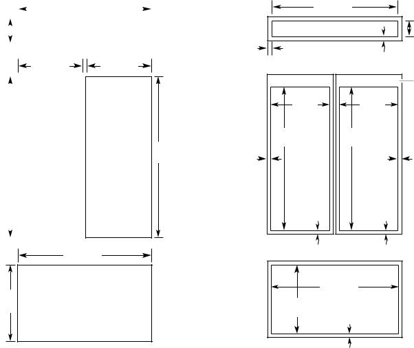
Custom Overlay Panels |
Custom Backer Panels |
(36" [91.4 cm] French Door Models) |
(36" [91.4 cm] French Door Models) |
|
|
|
|
|
|
|
3417⁄32" |
|
|
|
|
|
|
|
|
|
(87.7 cm) |
|
|
|
|
|
|
|
|
|
|
|
|
7¹⁄ " |
|
|
|
TOP GRILLE PANEL |
|||||
|
|
||||||||
(18.4 cm) |
|
|
|
Maximum Weight: 10 lbs (4.5 kg) |
|||||
|
|
|
|
|
|
|
|
|
|
171/16" (43.3 cm)
|
|
|
|
REFRIGERATOR |
|
|
|
|
|
513⁄8" |
|
|||
(130.5 cm) |
|
DOOR PANEL |
||
|
|
|
|
Maximum Weight: |
|
|
|
|
|
|
|
|
|
30 lbs (13.5 kg) |
|
|
|
|
|
|
|
|
|
|
171/16" (43.3 cm)
REFRIGERATOR DOOR PANEL
Maximum Weight: 30 lbs (13.5 kg)
3417⁄32" (87.7 cm)
207⁄16" FREEZER DOOR PANEL
(51.9 cm) Maximum Weight: 25 lbs (11.4 kg)
513⁄8" (130.5 cm)
3323/32" |
|
|
|
(85.6 cm) |
|
|
|
|
|
|
61/4" |
|
|
|
(15.9 cm) |
Side Offset |
|
Bottom Offset |
|
7/16" (1.1 cm) |
|
||
|
1/2" (1.27 cm) |
||
|
|
|
Exterior |
|
|
|
Panel |
|
|
|
extends |
1611/16" |
|
1611/16" |
above |
|
door. |
||
(42.4 cm) |
|
(42.4 cm) |
|
|
|
||
495/16" |
495/16" |
|
|
(125.2 cm) |
(125.2 cm) |
|
|
Side |
|
|
Side |
Offset |
|
|
Offset |
3/16" |
|
|
3/16" |
(4.7 mm) |
|
|
(4.7 mm) |
Bottom |
|
Bottom |
|
Offset |
|
Offset |
|
5/8" |
|
5/8" |
|
(1.6 cm) |
|
(1.6 cm) |
|
|
347/32" |
|
Side |
|
|
Offset |
|
(86.9 cm) |
|
5/32" |
|
203/32" |
|
|
(4 mm) |
(51.0 cm) |
|
|
|
|
|
Bottom offset |
|
|
|
3/16" (4.7 mm) |
|
13
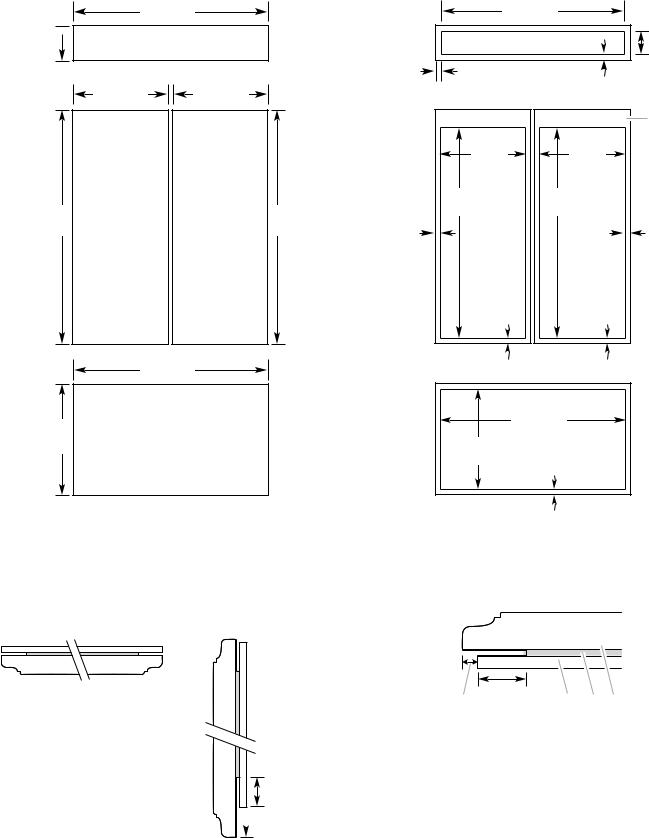
Custom Overlay Panels |
Custom Backer Panels |
(42" [106.7 cm] French Door Models) |
(42" [106.7 cm] French Door Models) |
7¹⁄" 
(18.4 cm)
51¹⁄"
(130.2 cm)
20¹⁄"
(51.4 cm)
40⁄" |
|
395/8" |
|
||
(102.7 cm) |
|
(100.6 cm) |
|
||
TOP GRILLE PANEL |
|
|
|
61/4" |
|
Maximum Weight: 10 lbs (4.5 kg) |
|
|
|
(15.9 cm) |
|
|
|
|
Side Offset |
Bottom Offset |
|
|
|
|
3/8" (9.5 mm) |
||
20" |
20" |
|
1/2" (1.27 cm) |
||
|
|
|
|
||
(50.8 cm) |
(50.8 cm) |
|
|
|
|
|
|
|
|
|
Exterior |
|
|
|
|
|
Panel |
|
|
|
|
|
extends |
|
|
|
195/8" |
195/8" |
above |
|
|
|
door. |
||
|
|
|
(49.85 cm) |
(49.85 cm) |
|
|
|
|
|
||
|
|
|
493/16" |
493/16" |
|
REFRIGERATOR |
REFRIGERATOR |
51¹⁄" |
(124.93 cm) |
(124.93 cm) |
|
|
|
|
|||
DOOR PANEL |
DOOR PANEL |
|
|
|
|
(130.2 cm) |
Side |
|
Side |
||
Maximum Weight: |
Maximum Weight: |
|
|
||
|
Offset |
|
Offset |
||
30 lbs (13.5 kg) |
30 lbs (13.5 kg) |
|
|
||
|
3/16" |
|
3/16" |
||
|
|
|
|
||
|
|
|
(4.7 mm) |
|
(4.7 mm) |
|
|
|
Bottom |
Bottom |
|
|
|
|
Offset |
Offset |
|
|
|
|
1/2" |
1/2" |
|
|
|
|
(1.27 cm) |
(1.27 cm) |
|
40⁄" |
|
|
|
|
|
(102.7 cm) |
|
|
|
|
|
|
|
|
|
40" |
|
FREEZER DOOR PANEL |
|
(101.6 cm) |
|
||
|
|
|
|
||
Maximum Weight: 25 lbs (11.4 kg) |
|
197/8" |
|
|
|
|
|
|
(50.48 cm) |
|
|
|
|
|
|
Offset all sides |
|
|
|
|
|
3/16" (4.7 mm) |
|
Spacer Panels (all models)
NOTE: Spacer panels must be at least 1" (2.54 cm) from the top, bottom, and side edges of the backer panel.
3-Piece Grille Overlay Panel Configuration
Top View
A.Offset dimension
B.¹ " (6.25 mm) Backer panel
C.¹ " (3.18 mm) Spacer panel
D.³ " (1.92 cm) Decorative overlay panel
Side View
 D
D
 C
C  B
B
1"
(2.54 cm)
 A
A
3-Piece Door Overlay Panel Configuration
1"
(2.54 cm)
A B C D
A.Offset dimension
B.¹ " (6.25 mm) Backer panel
C.¹ " (3.18 mm) Spacer panel
D.³ " (1.92 cm) Decorative overlay panel
1-Piece Overlay Panel Configuration
In some cases, your cabinet manufacturer may choose to work with one panel routed for the different dimensions. Follow these panel dimensions and placement instructions to be sure that the custom overlay panels will fit properly.
14
Stainless Steel and Overlay Series Both 36" and 42" models have the same cabinet side trim
All factory parts are available through your KitchenAid dealer or by calling KitchenAid Parts and Accessories at 1-800-442-9991. In Canada, call 1-800-807-6777.
Overlay Series Door Handle Kits
The following handle style is available. Contact your KitchenAid dealer or KitchenAid Parts and Accessories at
1-800-442-9991. In Canada, call 1-800-807-6777.
Knurl grip handle with chrome endcaps
W10782871 - French Door Bottom Mount Handle Kit
W10782874 - Two Door Bottom Mount Handle Kit
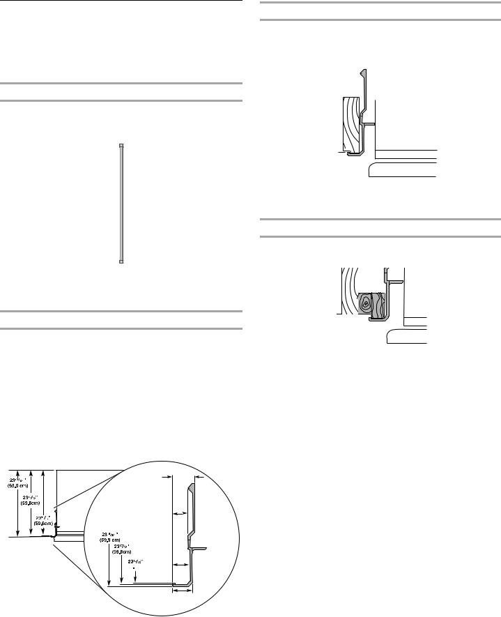
Refrigerator and Side Trim Dimensions
The width and height of a side panel are determined by the type of installation you are planning.
NOTES:
■The dimensions shown are actual product dimensions and may not reflect the needed panel installation dimensions.
■The side panel should be a minimum of ¹⁄ " (1.27 cm) thick to avoid warping.
■If the opening depth is 25" (63.5 cm) or more, you may want to install a support board on the rear wall.
Refrigerator
11/16" |
(18.0 mm) |
1/2" |
(12.2 mm) |
9/16"


 (13.9 mm)
5/8"
(15.7 mm)
Installation Dimensions - Option 1
1.Measure the distance from point A (as shown) to the back
wall. Add 1⁄16" (1.6 mm) to this measurement to allow the side panel to fit into the trim.
A
2.If the panel is more than ¹¹⁄ " (8.7 mm) thick, rout the front edge to allow the side panel to fit into the trim.
Installation Dimensions - Option 2
1. Measure the distance from point A (as shown) to back wall.
A |
2.Rout the front edge of the support board or attach a
¹¹⁄ " (8.7 mm) board to hold the panel in the cabinet side trim.
15
 Loading...