


KBSN608ESS
KitchenAid KBSN608ESS, KBSD608ESS, KBSN602ESS, KBSD618ESS, KBSN602EPA Installation Guide
...
SIDE BY SIDE BUILT-IN REFRIGERATOR
RÉFRIGÉRATEUR ENCASTRÉ CÔTE À CÔTE
REFRIGERADOR INCORPORADO DE LADO A LADO
Installation Guide/Guide d’installation/Guía de instalación
IMPORTANT: READ AND SAVE THESE INSTRUCTIONS. INSTALLATION REQUIRES 2 OR MORE PEOPLE.
IMPORTANT: LIRE ET CONSERVER CES INSTRUCTIONS. L’INSTALLATION NÉCESSITE 2 PERSONNES OU PLUS.
IMPORTANTE: LEA Y GUARDE ESTAS INSTRUCCIONES. PARA REALIZAR LA INSTALACIÓN SE REQUIEREN 2 O MÁS PERSONAS.
Table of Contents/Table des matières/Índice..................................................................2
W11311784A

TABLE OF CONTENTS/TABLE DES MATIÈRES/ÍNDICE
REFRIGERATOR SAFETY ..........................3
MODELS ......................................................4
INSTALLATION REQUIREMENTS .............5
Tools and Parts ........................................5
Location Requirements ............................5
Electrical Requirements ...........................6
Water Supply Requirements ....................7
Tipping Radius .........................................7
Product Dimensions .................................8
Door Swing Dimensions ...........................9
Overlay Series Door Panel and
Cabinetry Clearance...............................10
Overlay Series Custom Panels and
Handle Kits .............................................12
Custom Side Panels ...............................13
INSTALLATION INSTRUCTIONS .............14
Unpack the Refrigerator .........................14
Reduce Tipping Radius
(if required) ..............................................15
Move the Refrigerator into House ..........15
Install Anti-Tip Boards ............................15
Connect the Water Supply .....................16
Plug in Refrigerator ................................18
Move Refrigerator to Final Location ......18
Level and Align Refrigerator ...................18
Install Overlay Series Custom Panels ...19
Adjust Doors ...........................................20
Install Side Panel ....................................21
Install Base Grille ....................................21
Complete Installation .............................22
Water System Preparation .....................22
SÉCURITÉ DU RÉFRIGÉRATEUR...........23
MODÈLES .................................................24
EXIGENCES D’INSTALLATION ...............25
Outils et pièces ......................................25
Exigences d’emplacement .....................25
Spécications électriques ......................26
Spécications de l’alimentation en eau .27
Rayon de basculement ..........................27
Dimensions du produit ...........................28
Dimensions pour l’ouverture
des portes ..............................................29
Dégagement des panneaux de porte
de série Overlay et des armoires ...........30
Panneaux personnalisés de série
Overlay et ensembles de poignées........32
Panneaux latéraux personnalisés ..........33
INSTRUCTIONS D’INSTALLATION .........34
Déballage du réfrigérateur......................34
Réduire le rayon de basculement
(le cas échéant) ......................................35
Déplacement du réfrigérateur
dans le domicile .....................................35
Installation de planches
antibasculement .....................................35
Raccordement à la canalisation
d’eau .......................................................36
Brancher le réfrigérateur ........................38
Déplacement du réfrigérateur à son
emplacement dénitif .............................38
Réglage de l’aplomb et alignement
du réfrigérateur .......................................39
Installation des panneaux
personnalisés de série Overlay .............39
Ajustement des portes ...........................40
Installation du panneau latéral ...............41
Installation de la grille de la base ...........41
Terminer l’installation ..............................42
Préparation du circuit d’eau ...................42
SEGURIDAD DEL REFRIGERADOR .......44
MODELOS .................................................45
REQUISITOS DE INSTALACIÓN .............46
Herramientas y piezas ...........................46
Requisitos de ubicación .........................46
Requisitos eléctricos ..............................47
Requisitos del suministro de agua .........48
Arco de vuelco .......................................48
Dimensiones del producto .....................49
Medidas de oscilación de las puertas ...50
Espacio para el panel de la puerta de
la serie Overlay y para los gabinetes .....51
Paneles a la medida y juegos de
agarraderas de la serie Overlay .............53
Paneles laterales a la medida ................54
INSTRUCCIONES DE INSTALACIÓN .....55
Desembale el refrigerador ......................55
Cómo reducir el arco de vuelco
(de ser necesario) ...................................56
Cómo hacer entrar el refrigerador
en la casa ...............................................56
Cómo instalar los tableros
anti-vuelco ..............................................56
Conexión del suministro de agua ..........57
Cómo enchufar el refrigerador ...............59
Cómo mover el refrigerador a su
ubicación nal ........................................59
Nivelación y alineamiento
del refrigerador .......................................59
Instalación de los paneles a la medida
de la Serie Overlay ................................60
Cómo ajustar las puertas .......................61
Cómo instalar el panel lateral .................62
Instalación de la rejilla de la base ..........62
Completar la instalación ........................63
Preparación del sistema de agua ..........63

REFRIGERATOR SAFETY
Your safety and the safety of others are very important.
We have provided many important safety messages in this manual and on your appliance. Always read and obey all safety
messages.
This is the safety alert symbol.
This symbol alerts you to potential hazards that can kill or hurt you and others.
All safety messages will follow the safety alert symbol and either the word “DANGER” or “WARNING.”
These words mean:
You can be killed or seriously injured if you don't immediately
DANGER
WARNING
All safety messages will tell you what the potential hazard is, tell you how to reduce the chance of injury, and tell you what can
happen if the instructions are not followed.
WARNING
follow instructions.
You
can be killed or seriously injured if you don't
instructions.
follow
Tip Over Hazard
Refrigerator is top heavy and tips easily when not
completely installed.
Keep doors taped closed until refrigerator is
completely installed.
Use two or more people to move and install
refrigerator.
Failure to do so can result in death or serious injury.
3
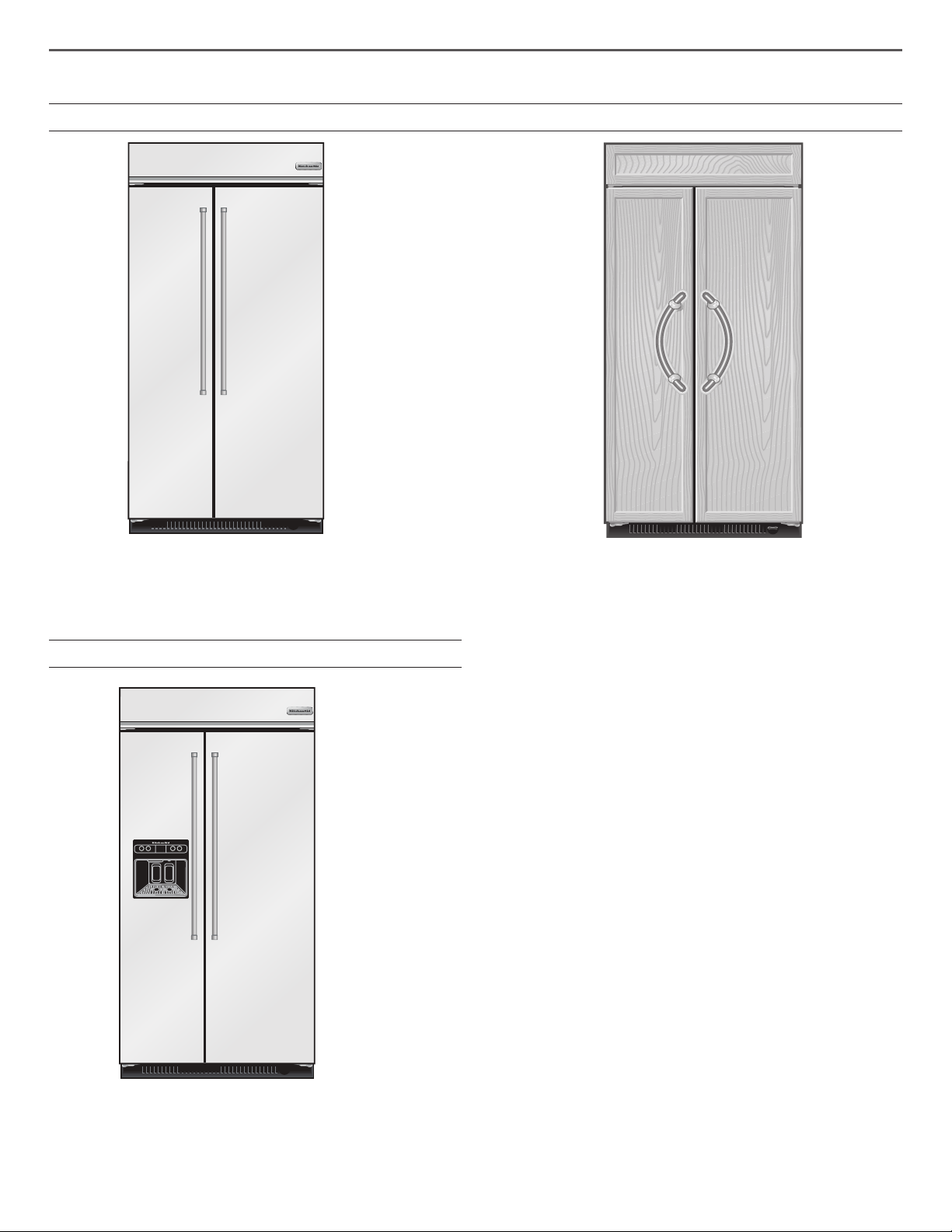
Side by Side Non-Dispensing Refrigerators
MODELS
Stainless Series
This series provides a warm commercial-looking built-in
refrigerator.
KBSN602ESS, KBSN608ESS
Side by Side Dispensing Refrigerators
Overlay Series
Features factory-installed, overlay style trim to provide a
“frameless” look. This series requires the installation of custom
panels, handles, and standoffs.
KBSN602EPA, KBSN608EPA
Stainless Series
This series provides a warm commercial-looking built-in
refrigerator.
KBSD606ESS,KBSD602ESS, KBSD608ESS, KBSD608EBS
4
INSTALLATION REQUIREMENTS
Tools and Parts
IMPORTANT:
■ Installer: Leave Installation Instructions with the homeowner.
■ Homeowner: Keep Installation Instructions for future
reference. Save these Installation Instructions for the local
electrical inspector’s use.
Tools Needed
Gather the required tools and parts before starting installation.
Read and follow the instructions provided with any tools listed
here.
■ Cordless drill ■ Torx
■ Drill bits ■ 11/32" nut driver
■ Adjustable wrenches (2) ■ 3/8", 1/4", and 1/2"
†
T27 screwdriver
open-end wrenches
■ Phillips screwdriver ■ 5/32" hex key
■ Small level ■ 1/4" and 5/16" socket
drivers
■ Appliance dolly ■ Tape measure
■ Utility knife
Parts Needed
■ #8 x 3" (7.6 cm) wood screws (longer screws may be needed)
(6)
■ 2" x 4" x 32" (5 cm x 10 cm x 81 cm) wood board(s) (1 or 2)
■ Make custom panels or consult a qualied cabinetmaker or
carpenter to make the panels.
Overlay Series: Make custom panels, or consult a qualied
cabinetmaker or carpenter to make the panels. See “Overlay
Series Custom Panels and Handle Kits” for more information.
Stainless is shipped complete.
■ If you are conneckting the water line directly to copper tubing
and not to a shutoff valve, you need a ferrule, a union, and a
1/4" (6.35 mm) compression tting.
Location Requirements
The refrigerator can be recessed in an opening between cabinets
or installed at the end of a cabinet run using a side panel to
enclose the refrigerator.
WARNING
■ Staff kitchen areas in shops, ofces and other working
environments.
■ Farm houses and by clients in hotels, motels and other
residential type environments.
■ Bed and breakfast type environments.
■ Catering and similar non-retail applications.
■ Observe all governing codes and ordinances.
■ Floor must support the refrigerator weight, more than
600 lbs(272 kg), door panels and contents of the refrigerator.
■ Ceiling height must allow for side tipping radius. See “Tipping
Radius.”
■ Location should permit door to open fully. See “Door Swing
Dimensions.”
■ Location must permit top grille removal. See “Opening
Dimensions.”
NOTE: The refrigerator is intended for use in a location where
the temperature ranges from a minimum of 55°F (13°C) to a
maximum of 110°F (43°C). The preferred room temperature range
for optimum performance, which reduces electricity usage and
provides superior cooling, is between 60°F (15°C) and 90°F (32°C).
It is recommended that you do not install the refrigerator near a
heat source, such as an oven or radiator.
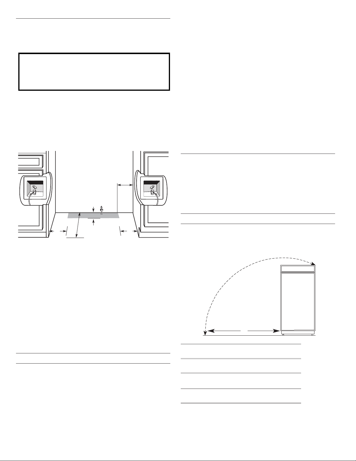
Opening Dimensions
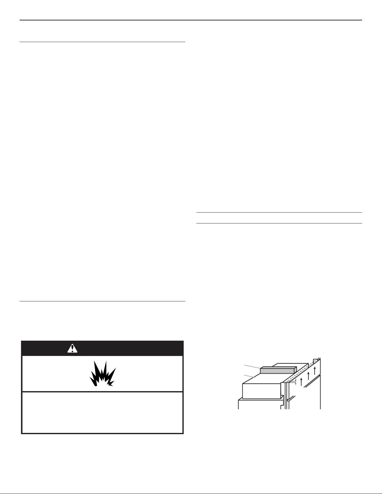
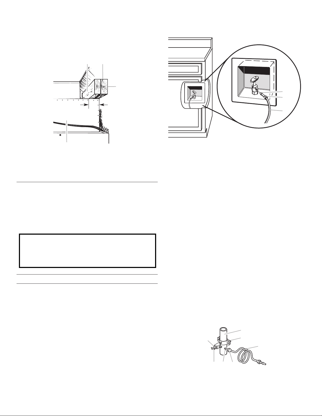
■ To avoid tipping during use, the solid soft must be within
1" (2.5 cm) maximum above the refrigerator. If the solid soft
is higher than 1" (2.5 cm) or one is not available, then the
refrigerator must be braced.
If anti-tip boards are needed, they must be installed to the
rear wall studs so that the bottom of the anti-tip board is
84" (213.4 cm) from the oor. See “Install Anti-Tip Boards” for
more information.
NOTES:
■ A clearance of 1/2" (1.3 cm) must be maintained above
the top grille in order for the top grille to be removed.
■ Do not remove the foam gasket on top of the compressor
cover unless removal is necessary to t the unit under a
soft. Removal of the gasket will cause loss in cooling
efciency.
■ If installing under a solid soft, after, installation raise the
leveling legs so that the gasket is pressed snugly against
the soft.
Explosion Hazard
Keep flammable materials and vapors, such as
gasoline, away from refrigerator.
Failure to do so can result in death, explosion, or fire.
IMPORTANT: This refrigerator is designed for indoor, household
use only.
This appliance is intended to be used in household and similar
applications such as:
†
TORX is a trademark of Acument Intellectual Properties, LLC
A
B
1/2"
(1.3 cm)
A. Gasket
B. Compressor cover
■ A grounded 3 prong electrical outlet should be located
within a specied number of inches from the right-hand
side cabinets or end panel. See the chart following the
graphic for the number of inches required for your model.
For more information, see “Electrical Requirements.”
5
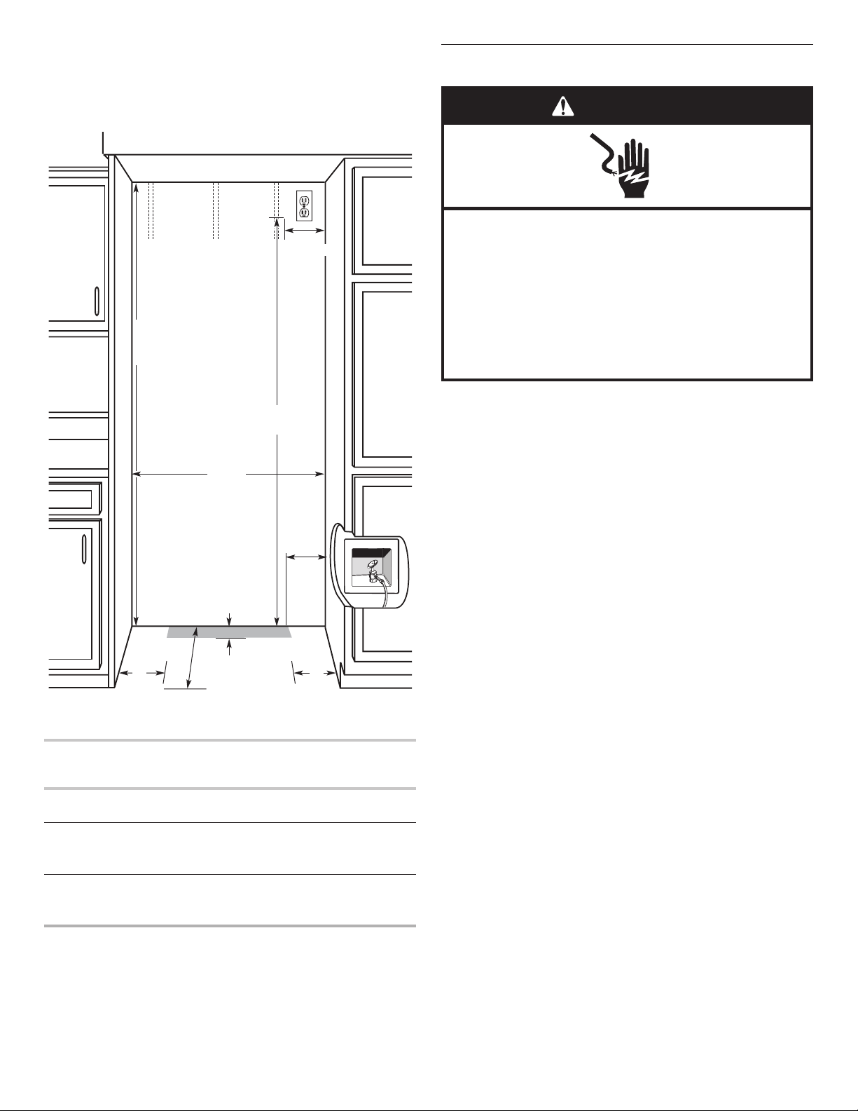
■ The water shutoff should be located in the base cabinet on
either side of the refrigerator or some other easily accessible
area. If the water shutoff valve is not in the cabinets, the
plumbing for the water line can come through the oor or the
back wall. See “Water Supply Requirements” for more
information.
80" - 90"
(203-229 cm)
B
Dimension
83¹⁄2" (212.1 cm) min.
84³⁄4" (215 cm) max.
to bottom of solid soffit
Electrical Requirements
WARNING
Electrical Shock Hazard
Plug into a grounded 3 prong outlet.
Do not remove ground prong.
Do not use an adapter.
Do not use an extension cord.
Failure to follow these instructions can result in death,
fire, or electrical shock.
77"
(196 cm)
A
Width
(see chart following)
6"
(15.2 cm)
24"
(60.96 cm) min.
1"
(2.54 cm)
Model Width A (as shown
above)
36 35½" to 35¾"
(90.2 cm to 90.8 cm)
42 41½" to 41¾"
(105.4 cm to 106 1 cm)
6"
(15.2 cm)
6"
(15.2 cm)
Dimension
B (as shown
above)
4" (10.2 cm)
7½" (19 1 cm)
Before you move your refrigerator into its nal location, it is
important to make sure you have the proper electrical connection.
If the supply cord is damaged, it must be replaced by the
manufacturer or its service agent or a similar qualied person. Do
not use a cord that shows cracks or abrasion damage along its
length or at either the plug or connection end.
Recommended Grounding Method
A 115 V, 60 Hz, AC only, 15 or 20 A fused, grounded electrical
supply is required. It is recommended that a separate circuit
serving only your refrigerator be provided. Use an outlet that
cannot be turned off by a switch. Do not use an extension cord.
IMPORTANT: If this product is connected to a GFCI (Ground
Fault Circuit Interrupter) protected outlet, nuisance tripping of the
power supply may occur, resulting in loss of cooling. Food quality
and avor may be affected. If nuisance tripping has occurred, and
if the condition of the food appears poor, dispose of it.
NOTE: Before performing any type of installation or cleaning,
remove the top grille and turn the master power switch to OFF or
disconnect power at the circuit breaker box.
When you are nished, turn ON the master power switch or
reconnect power at the circuit breaker box. Then reset the control
to the desired setting.
48 47½" to 47¾"
13½" (34.3 cm)
(120.7 cm to 121.3 cm)
NOTE: Flooring under refrigerator must be at same level as the
room. Face of cabinetry must be plumb.
6
Water Supply Requirements
■ All installations must meet local plumbing code requirements.
■ Connect to potable water supply only
Do not use with water that is microbiologically unsafe or
of unknown quality without adequate disinfection before
or after the system. Systems certified for cyst reduction
may be used on disinfected waters that may contain
filterable cysts.
■ The water shutoff should be located in the base cabinet on
either side of the refrigerator or some other easily accessible
area. The right-hand side is recommended. The access hole
through the cabinet must be within 1/2" (1.3 cm) of the rear
wall.
NOTE: If the water shutoff valve is in the back wall behind the
refrigerator, it must be at an angle so that the tube is not
kinked when the refrigerator is pushed into its nal location.
6"
(15.2 cm)
Reverse Osmosis Water Supply
IMPORTANT: The pressure of the water supply coming out of
a reverse osmosis system going to the water inlet valve of the
refrigerator needs to be between 30 and 120 psi
(207 and 827 kPa).
If a reverse osmosis water ltration system is connected to your
cold water supply, the water pressure to the reverse osmosis
system needs to be a minimum of 40 to 60 psi (276 to 414 kPa).
If the water pressure to the reverse osmosis system is less than
40 to 60 psi (276 to 414 kPa):
■ Check to see whether the sediment lter in the reverse
osmosis system is blocked. Replace the lter if necessary.
■ Allow the storage tank on the reverse osmosis system to rell
after heavy usage.
■ If your refrigerator has a water lter, it may further reduce
the water pressure when used in conjunction with a reverse
osmosis system. Remove the water lter. See “Water Filtration
System.”
If you have questions about your water pressure, call a licensed,
qualied plumber.
Tipping Radius
Be sure there is adequate ceiling height to stand the refrigerator
upright when it is moved into place.
■ The dolly wheel height must be added to the tipping radius
when a dolly is used.
■ If needed, the tipping radius can be reduced. See “Reduce
Tipping Radius.
1"
6"
(15.2 cm)
(60.96 cm) min
■ If the water shutoff valve is not in the cabinets, the plumbing
(2.54 cm)
24"
6"
(15.2 cm)
for the water line can come through the oor. A 1/2" (12.7 mm)
hole for plumbing should be drilled at least 6" (15.2 cm) from
the right-hand or left-hand side cabinet or panel. On the oor,
the hole should be no more than 1" (2.54 cm) away from the
back wall. See “Connect the Water Supply.”
■ If additional tubing is needed, use copper tubing and check
for leaks. Install the copper tubing only in areas where the
household temperatures will remain above freezing.
■ Do not use a piercing-type or 3/16" (4.76 mm) saddle valve
which reduces water ow and clogs more easily.
NOTE: Your refrigerator dealer has a kit available with a
1/4" (6.35 mm) saddle-type shutoff valve, a union, and copper
tubing. Before purchasing, make sure a saddle-type valve
complies with your local plumbing codes.
Water Pressure
A cold water supply with water pressure between 30 and 120 psi
(207 and 827 kPa) is required to operate the water dispenser and
ice maker. If you have questions about your water pressure, call a
licensed, qualied plumber.
NOTE: If the water pressure is less than what is required, the ow
of water from the water dispenser could decrease or ice cubes
could be hollow or irregular shaped. If you have questions about
your water pressure, call a licensed, qualied plumber.
Side Tapping Radius
The side tipping radius varies depending upon the width of the
model. Use the chart provided to determine the side tipping
radius.
NOTE: Tip on side only.
A
Model Tipping Radius A
36 90½" (229.9 cm)
42 93" (236.2 cm)
48 96" (243.8 cm)
7
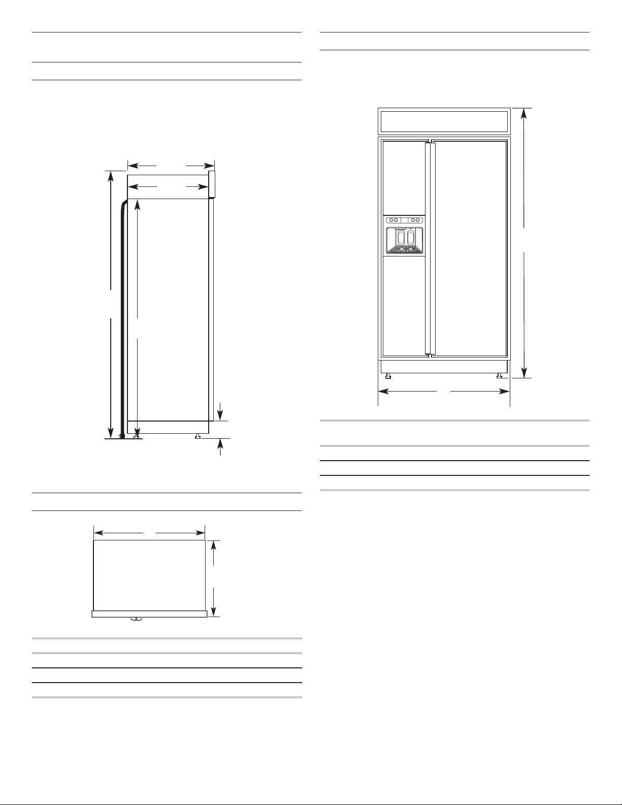
Product Dimensions
Side View
■ The depth from the front of the top grille to the back of the
refrigerator cabinet is 253/8" (64.5 cm).
■ The power cord is 84" (213 cm) long.
■ Height dimensions are shown with leveling legs extended
1/8" (3 mm) below the rollers.
253/8"
(64.5 cm)
231/2"
(59.7 cm)
*833/8"
(211.8 cm)
84"(213.4 cm)
Power Cord
Front View
■ Width dimensions were measured from trim edge to trim
edge.
■ Height dimensions are shown with leveling legs extended
1/8" (3 mm) below the rollers.
*83³⁄8"
(211.8 cm)
*3¹⁄2" (8.9 cm)
*When leveling legs are fully extended to 1¹⁄4" (3.2 cm) below
rollers, add 1¹⁄8" (2.9 cm) to the height dimensions.
Top View
A
25³⁄8"
(64.5 cm)
Model Width A
36
42
48
35" (88.9 cm)
41" (104.1 cm)
47" (119.4 cm)
(see chart following)
A
Model Width A (Trim edge to trim
edge)
36 36¹¹⁄32" (92.3 cm)
42 42¹¹⁄32" (107.5 cm)
48 48¹¹⁄32" (122.8 cm)
*When leveling legs are fully extended to 1¹⁄4" (3.2 cm) below
rollers, add 1¹⁄8" (2.9 cm) to the height dimensions.
8
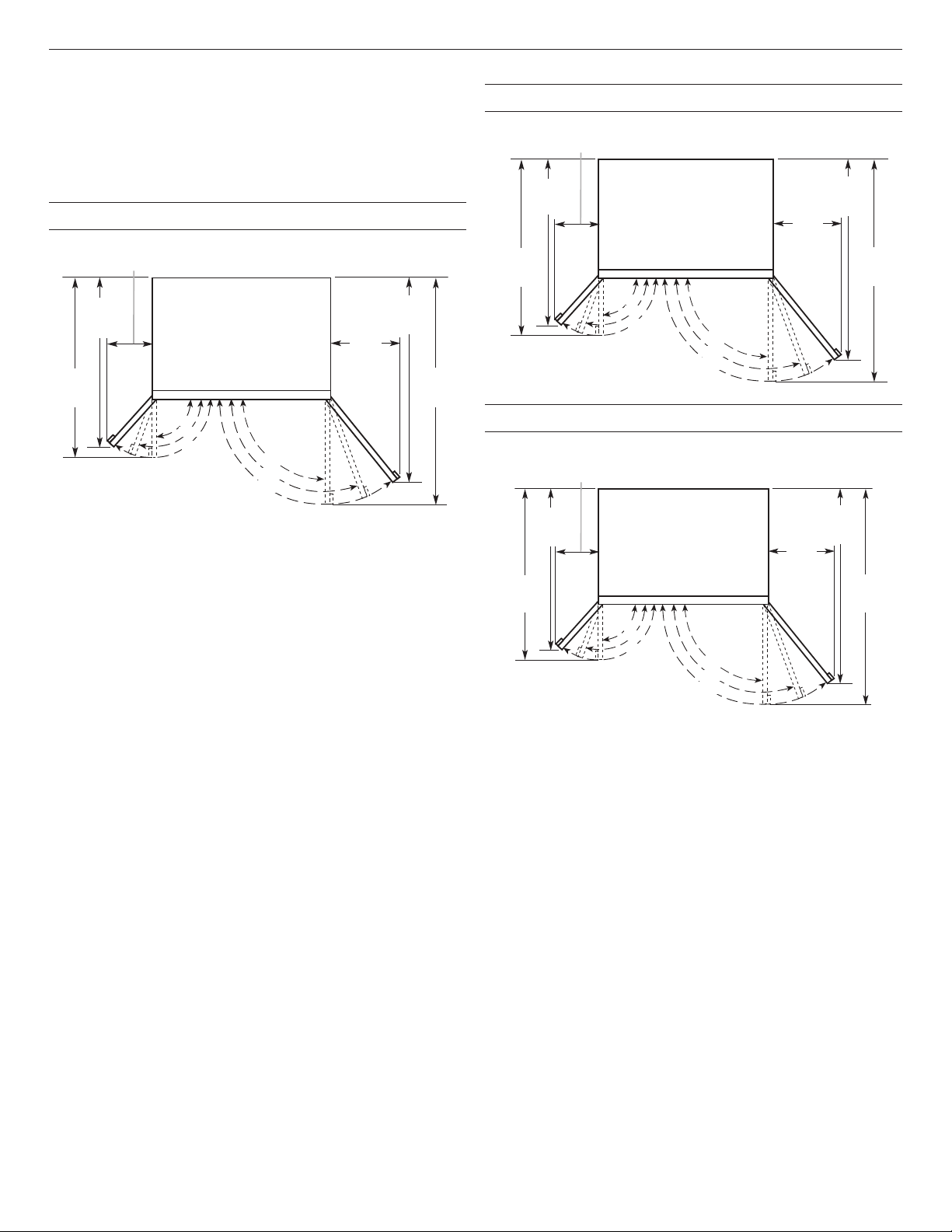
Door Swing Dimensions
The location must permit both doors to open to a minimum of
90°. Allow 5" (12.7 cm) minimum space between the side of the
refrigerator and a corner wall.
NOTE: More clearance may be required if you are using overlay
panels, custom handles, or extended handles on a Classic model.
To adjust the door swing, see “Adjust Doors.”
36" (91.4 cm) Models
107⁄8"
(27.6 cm)
42" (106.7 cm) Models
125⁄8"
(32.1 cm)
371⁄4"
(94.6 cm)
413⁄8"
(105.1 cm)
411⁄2"
(105.4 cm)
167⁄8"
(42.9 cm)
477⁄8"
(121.6 cm)
(90.2 cm)
387⁄8"
(98.7 cm)
351⁄2"
90°
110°
130°
110°
130°
90°
143⁄8"
(36.5 cm)
39"
(99.1 cm)
(112.7 cm)
443⁄8"
90°
110°
130°
48" (121.9 cm) Models
143⁄8"
(36.5 cm)
39"
(99.1 cm)
437⁄8"
(111.4 cm)
90°
110°
130°
130°
90°
110°
130°
90°
110°
44"
(111.8 cm)
191⁄4"
(48.9 cm)
513⁄8"
(130.5 cm)
9
Overlay Series Door Panel and Cabinetry Clearance
The custom door panels and adjacent cabinetry must be designed so that there is sufcient clearance for the doors to swing open. If the
refrigerator is to be installed close to the wall, see “Door Swing 90°” on next page.
Door Swing 110°
Actual Size
Refrigerator to
Cabinetry Clearance
Refrigerator
Side Trim
11⁄2"
(3.8 cm)
11⁄4"
(3.2 cm)
1"
(2.5 cm)
Cabinetry
1/4"
(6.35 mm)
Hinge
1/2"
(1.3 cm)
3/4"
(1.9 cm)
1"
(2.5 cm)
NOTE: For Overlay Series models, rout
the hinge side of the custom door panels
to a radius that is equal to at least half the
thickness of the panel if a 130° door swing
is desired. See “Adjust Doors.”
Door
1/2"
(1.3 cm)
Backer Panel
3/4"
(1.9 cm)
Overlay Panel
Spacer Panel
NOTE: Allow
1/2" (1.3 cm) clearance
between overlay panel
and cabinetry.
1"
(2.5 cm)
11⁄4"
(3.2 cm)
11⁄2"
(3.8 cm)
When the doors are closed the refrigerator will extend beyond the face of the adjacent cabinetry to some degree.
10
90° Door
Stop Position
Hinge
Refrigerator
Side Trim
(1.3 cm)
Cabinetry
Door Swing 90°
Actual Size
Refrigerator to
Cabinetry Clearance
(2.5 cm)
3/4"
(1.9 cm)
1/2"
1"
1/4"
(6.35 mm)
1/2"
(1.3 cm)
3/4"
(1.9 cm)
1"
(2.5 cm)
1/2"
(1.3 cm)
3/4"
(1.9 cm)
1"
(2.5 cm)
11⁄4"
(3.2 cm)
11⁄2"
(3.8 cm)
Door
Backer Panel
Spacer Panel
Overlay Panel
Allow a minimum of 5" (12.7 cm) of space between the side of the refrigerator and a corner wall. More clearance may be needed if
thicker custom panels or custom handles are used. Do not overlook base boards.
11
Overlay Series Custom Panels and Handle
Kits
Custom overlay panels allow you to blend the exterior of your
refrigerator into the overall kitchen decor, and to use custom
handles for additional design exibility.
The custom panels must have backer panels attached in order to
mount them to the refrigerator. It is most common to work with
three panels, as shown in the following graphic: a decorative
overlay panel, a 1/8" (3.18 mm) spacer panel or spacer strips and
a 1/4" (6.35 mm) backer panel.
In some cases, your cabinet manufacturer may choose to work
with one panel routed for the different dimensions. Follow these
panel dimension and placement instructions to be sure that the
custom overlay panels will t properly.
IMPORTANT:
■ The weight of the refrigerator door overlay panel cannot
exceed 50 lbs (23 kg).
■ The weight of the freezer door overlay panel cannot exceed
40 lbs (18.1 kg).
■ The weight of the top grille overlay panel cannot exceed
10 lbs (4.5 kg).
To minimize panel weight, you may use 2" (5.08 cm) spacer strips
around the perimeter in place of full-sheet solid spacer panels. The
spacer strips must be set in at least 1" (2.54 cm) from the top,
bottom and sides edges of the backer panel. If you use spacer
strips, it is also recommended that you use two 2" (5.08 cm) strips
horizontally centered for added support.
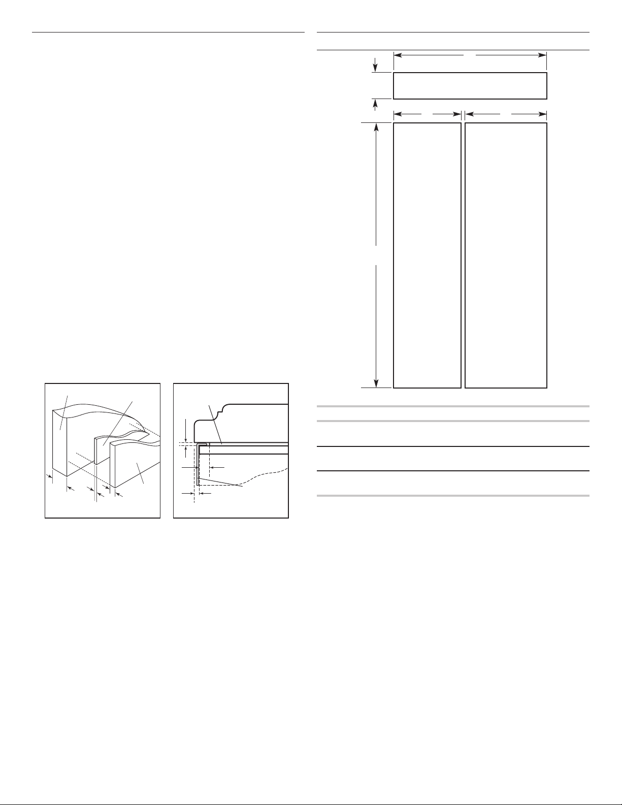
Decorative Overlay Panel
71⁄4"
(18.4 cm)
A B
721⁄4"
(183.5 cm)
Freezer
Door Panel
(Non-Dispenser)
C
Grille Panel
Refrigerator
Door Panel
Overlay Panel
5/8" to 3/4"
(15.88 to
19.05 mm)
1/8"
(3.18 mm)
Spacer Panel
Backer Panel
1/4"
(6.35 mm)
Spacer Panel
1/8"
(3.18 mm)
Overlay Panel
Backer Panel
1" minimum
(2.54 cm)
Offset Dimension
Door/Grille Trim
Model A B C
36 14³/4"
(37.47 cm)
42 17¹/4"
(43.82 cm)
48 19³/4"
(50.17 cm)
19³/4"
(50.17 cm)
23¹/4"
(59.06 cm)
26³/4"
(67.95 cm)
34³/4"
(88.27 cm)
40³/4"
(103.51 cm)
46³/4"
(118.75 cm)
12
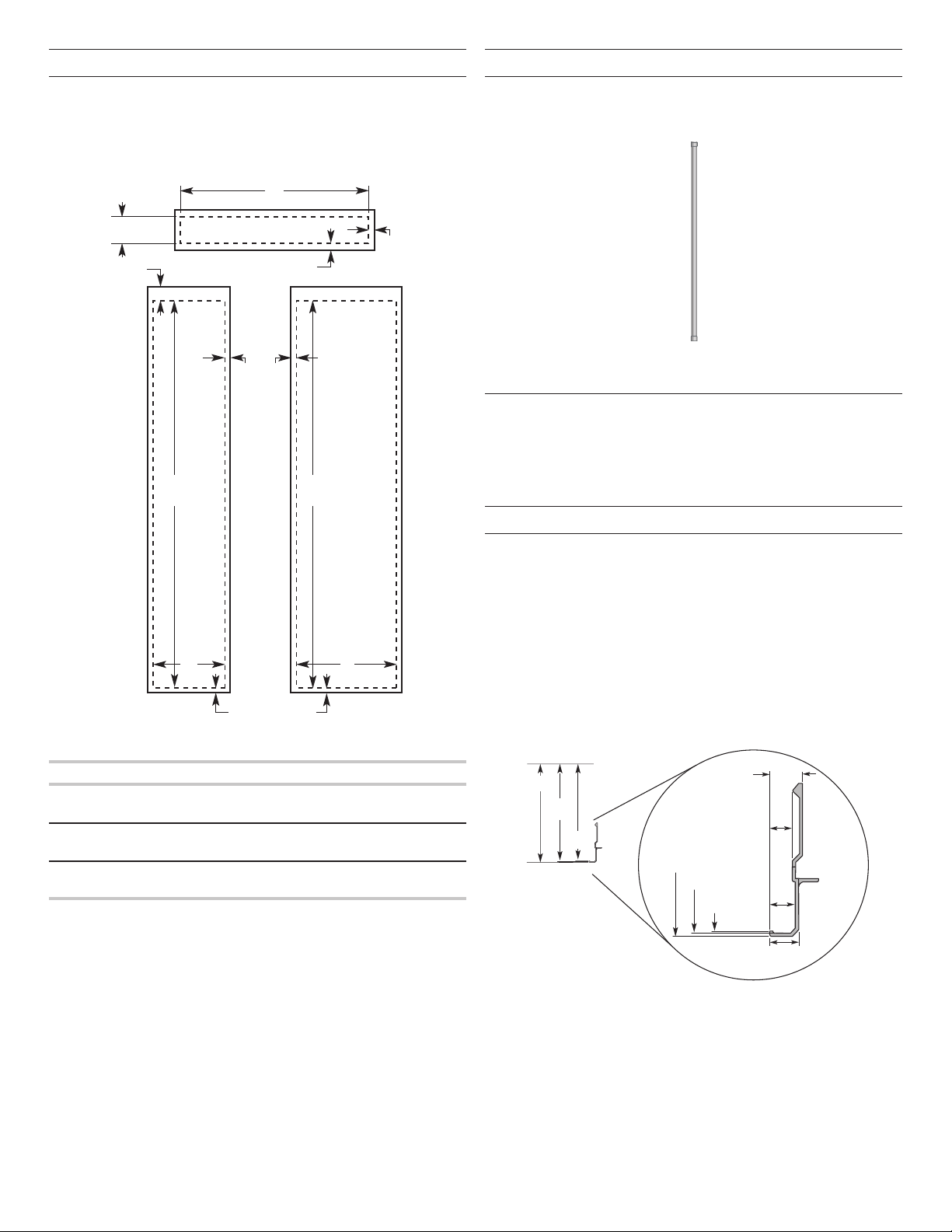
Backer Panels
Overlay Series Door Handle Kits
NOTES:
■ Dashed lines represent placement of backer panels on overlay
panels.
■ Illustration shows backer panels placed on decorative
overlays.
C
63⁄16"
(15.7 cm)
Top Offset
15⁄8" (4.13 cm)
701⁄2"
(179.1 cm)
Bottom Offset
1/2" (1.27 cm)
Handle
Side Offset
1/4"
(6.4 cm)
701⁄2"
(179.1 cm)
Side Offset
1/2" (1.27 cm)
The following handle style is available. Contact your KitchenAid
dealer or KitchenAid Parts and Accessories at 1-800-442-9991. In
Canada, call 1-800-807-6777.
Knurl grip handle with chrome endcaps - W10782873
Custom Side Panels
Custom side panels may be needed when not enough space is
available to have cabinets on both sides of the refrigerator or when
the refrigerator is placed at the end of a cabinet run. You may
choose an Inset, Flush, or Recessed Inset panel installation.
Refrigerator and Side Trim Dimensions
BA
Bottom Offset
1/8" (3.2 mm)
Model D E F
36 14¹/4"
(36.20 cm)
42 16³/4"
(42.55 cm)
48 19¹/4"
(48.90 cm)
19¹/4"
(48.90 cm)
22³/4"
(57.79 cm)
26¹/4"
(66.68 cm)
33³/4"
(85.73 cm)
39³/4"
(100.97 cm)
45³/4"
(116.21 cm)
The width and height of a side panel are determined by the type of
installation you are planning.
NOTES:
■ The dimensions shown are actual product dimensions and
may not reect the needed panel installation dimensions.
■ The side panel should be a minimum of 1/2" (1.27 cm)
thick to avoid warping.
■ If the opening depth is 25" (63.5 cm) or more, you may
want to install a support board on rear wall.
Side Trim
11/16"
2317⁄32"
(59.8 cm)
2315⁄32"
(59.6 cm)
(18.0 mm)
(12.2 mm)
(13.9 mm)
1/2"
9/16"
5/8"
(15.7 cm)
2319⁄32"
(59.9 cm)
2317⁄32"
(59.8 cm)
2315⁄32"
(59.6 cm)
2319⁄32"
(59.9 cm)
13
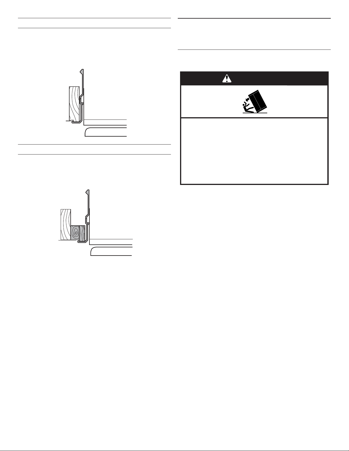
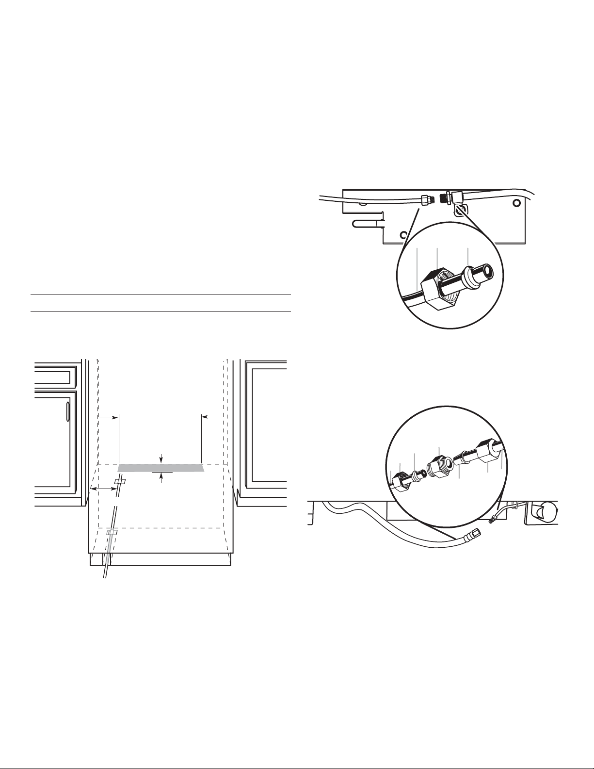
Installation Dimensions (Option 1)
A
1. Measure the distance from point A (as shown) to the back
wall. Add 1/16" (1.6 mm) to this measurement to allow the side
panel to t into the trim.
2. If the panel is more than 11/32" (8.7 mm) thick, route the front
edge to allow the side panel to t into the trim.
Installation Dimensions (Option 2)
1. Measure the distance from point A (as shown) to back wall.
2. Route the front edge of the support board or attach a
3/8" (9.5 mm) board to hold the panel in the cabinet side trim.
INSTALLATION
INSTRUCTIONS
Unpack the Refrigerator
WARNING
Tip Over Hazard
Refrigerator is top heavy and tips easily when not
completely installed.
Keep doors taped closed until refrigerator is
completely installed.
Use two or more people to move and install
refrigerator.
Failure to do so can result in death or serious injury.
IMPORTANT:
■ Do not remove the lm covering until the refrigerator is in its
operating location.
■ All four leveling legs must contact the oor to support and
stabilize the full weight of the refrigerator.
■ Keep the cardboard shipping piece or plywood under the
A
refrigerator until it is installed in the operating location.
1. Remove and save the literature package bag taped to the side
of the refrigerator and the parts bag behind the grille. Remove
the four brackets (two on each side) that attach the shipping
base to the refrigerator bottom.
NOTE: Do not remove tape and door bracing until the
refrigerator is in its nal location.
2. If necessary, reduce the tipping radius. See “Tipping Radius”
for ceiling height requirements or “Reduce Tipping Radius”
for step-by-step instructions. If you do not need to reduce the
tipping radius, proceed to “Move the Refrigerator into House.”
14

Reduce Tipping Radius
(if required)
Before bringing the refrigerator into the home, be sure there is
adequate ceiling height to stand the refrigerator upright. See
“Tipping Radius” in the “Installation Requirements” section for
more information.
If you do not have adequate ceiling height to stand the refrigerator
upright, the tipping radius can be reduced by removing the top
grille and side trims (see the following chart).
Model Reduced Tipping Radius
36 89" (225.9 cm)
42 90¹⁄2" (229.9 cm)
48 91¹⁄4" (231.8 cm)
1. Grasp both ends of the top grille.
2. Push the top grille straight up; then pull straight out. Lay the
grille on a soft surface.
B BA
NOTE: Pass the dolly strap under the handles for the Stainless
Series.
2. Place pieces of the shipping carton on the oor when rolling
the dolly and refrigerator into the house. Move the refrigerator
close to the built-in opening.
3. Place top of cardboard carton or plywood under refrigerator.
4. Stand the refrigerator up. First, place the left bottom edge of
the refrigerator on the oor, stand the refrigerator upright and
then lower the right-hand side of the refrigerator to the oor.
5. Reassemble the trim and top grille after the dolly has been
removed from the refrigerator.
A. Top grille
B. Cabinet side trim
3. Remove the six screws attaching each cabinet side trim to the
refrigerator and remove the side trims.
Move the Refrigerator into House
WARNING
Tip Over Hazard
Refrigerator is top heavy and tips easily when not
completely installed.
Keep doors taped closed until refrigerator is
completely installed.
Use two or more people to move and install
refrigerator.
Failure to do so can result in death or serious injury.
Install Anti-Tip Boards
IMPORTANT:
■ To avoid tipping during use, the solid soft must be within
1" (2.5 cm) maximum above the refrigerator. If the solid soft
is higher than 1" (2.5 cm) or one is not available, then the
refrigerator must be braced.
■ It is recommended that board(s) be installed before the
refrigerator is installed.
■ Board(s) must be long enough to fully cover the width of the
compressor cover.
■ Locate the board(s) so the bottom surface(s) of the board(s)
is(are) 84" (213 cm) from the oor.
■ During installation, raise the refrigerator up so there is
1/4" (6.35 mm) maximum between the top of the refrigerator
and the bottom of the anti-tip board(s). Do not crush the
compressor cover when raising the rear leveling legs.
NOTE: The foam gasket, on top of the compressor cover, will
compress to t under the anti-tip board(s). There is no need to
trim the gasket.
1. Place an appliance dolly under the left side of the refrigerator
as shown. Place the corner posts from the packing materials
over the trims and handles as appropriate to avoid damage.
Slowly tighten the strap.
15
To Install Anti-tip Boards
1. Mark the stud locations on rear wall.
2. Securely attach one or two 2" x 4" x 32" (5 cm x 10 cm x 81
cm) boards to wall studs behind refrigerator. Use six #8 x 3"
(7.6 cm) (or longer) wood screws. The wood screws must be
screwed into the studs at least 11/2" (3.8 cm). The board(s)
must overlap the compressor cover.
BA
2. Connect the exible, codes-approved water supply line to the
water shutoff valve by threading the provided nut onto the
shutoff valve as shown.
C
2" (5 cm)
D
A. Center board 1/4" (6.35 mm)
max. above refrigerator
B. Two 2" x 4" x 32"
(5 cm x 10 cm x 81 cm) boards
C. Attach to studs with six
#8 x 3" (7.6 cm) screws
D. Compressor cover
Connect the Water Supply
Read all directions before you begin.
IMPORTANT:
■ If you turn the refrigerator on before the water line is
connected, turn the ice maker OFF.
■ Connect to potable water supply only.
Do not use with water that is microbiologically unsafe or
of unknown quality without adequate disinfection before
or after the system. Systems certified for cyst reduction
may be used on disinfected waters that may contain
filterable cysts.
Connect to Water Line
Parts Needed
■ Minimum 7 ft (2.13 m) exible, codes-approved water supply
line
Style 1—Shutoff Valve Connection
NOTE: If your water line connection does not look like Style 1, see
“Style 2—Copper Line Connection.”
1. Unplug refrigerator or disconnect power supply.
IMPORTANT:
■ There is not enough clearance to achieve a ush installation
if a water shutoff valve is located in the wall behind the
refrigerator. The water shutoff should be located in the base
cabinet on either side of the refrigerator.
■ Before attaching the tubing to shutoff valve, ush the main
water supply line to remove particles and air in the water line.
Allow enough ow so that water becomes clear. Flushing the
water line may help avoid lters and/or water valves from
becoming clogged.
16
A
B
C
A. Bulb
B. Nut
C. Water tubing
3. Place the end of the tubing into a bucket, and turn shutoff
valve ON.
4. Check for leaks. Tighten any nuts or connections (including
connections at the valve) that leak.
Style 2—Copper Line Connection
NOTE: If there is a water supply line that meets the specications
in “Water Supply Requirements,” proceed to “Connecting to
Refrigerator.” If not, use the following instructions to connect to
the household cold water supply.
1. Unplug refrigerator or disconnect power.
2. Turn OFF main water supply. Turn ON nearest faucet long
enough to clear line of water.
3. Locate a 1/2" to 1¹⁄4" (1.3 cm to 3.18 cm) vertical cold water
pipe near the refrigerator.
IMPORTANT:
■ Make sure it is a cold water pipe.
■ Horizontal pipe will work, but drill on the top side of the
pipe, not the bottom. This will help keep water away from
the drill and keep normal sediment from collecting in the
valve.
4. Determine the length of copper tubing you need. Measure from
the connection on the refrigerator to the water pipe. Add
7 ft (2.1 m) to allow for cleaning. Use 1/4" (6.35 mm) O.D.
(outside diameter) copper tubing. Be sure both ends of copper
tubing are cut square.
5. Using a cordless drill, drill a 1/4" (6.35 mm) hole in the cold
water pipe you have selected.
A
G
B
C
DEF
A. Cold water pipe
B. Pipe clamp
C. Copper tubing
D. Compression nut
E. Compression sleeve
F. Shutoff valve
G. Packing nut
6. Fasten the shutoff valve to the cold water pipe with the pipe
clamp. Be sure the outlet end is solidly in the 1/4" (6.35 mm)
drilled hole in the water pipe and that the washer is under the
pipe clamp. Tighten the packing nut. Tighten the pipe clamp
screws slowly and evenly so washer makes a watertight seal.
Do not overtighten.
IMPORTANT: Before attaching the tubing to shutoff valve, ush
the main water supply line to remove particles and air in the water
line. Allow enough ow so that water becomes clear. Flushing
the water line may help avoid lters and/or water valves from
becoming clogged.
7. Slip the compression sleeve and compression nut on the
copper tubing as shown. Insert the end of the tubing into the
outlet end squarely as far as it will go. Screw compression nut
onto outlet end with adjustable wrench. Do not overtighten the
clamp or the sleeve. This will crush the copper tubing.
8. Turn off the shutoff valve on the water pipe. Coil the copper
tubing.
9. Connect the exible, codes-approved water supply line to the
water shutoff valve by threading the provided nut onto the
shutoff valve.
10. Place the end of the tubing into a bucket, and turn shutoff
valve ON.
11. Check for leaks around the saddle valve. Tighten any nuts or
connections (including connections at the valve) that leak.
Connect to Refrigerator
4. Tape the 7 ft (2.13 m) exible codes-approved water supply
line to the oor, 7" (17.78 cm) from the left side of the
refrigerator. Tape along the length of the tubing, which will
allow it to pass beneath the refrigerator without interference.
NOTE: Allow a minimum of 26" (66.04 cm) of exible codesapproved water supply line to be loose at the front of the
refrigerator for connecting to the refrigerator.
5. Connect the 7 ft (2.13 m) exible codes-approved water supply
line to the refrigerator.
NOTE: If the main water shutoff valve is behind the refrigerator,
a secondary water shutoff valve may be installed in line with
the water supply line at the front of the product.
Overmold Coupling (on some models)
AB C
Parts Supplied
■ 1/4" to 1/4" (6.35 mm to 6.35 mm) male-to-male coupling (on
some models)
6" (15.2 cm) 6" (15.2 cm)
7"
(17.78 cm)
1" (2.54 cm)
NOTE: The exible, codes-approved water supply line should
connect to the supply valve through the oor.
1. Unplug the refrigerator or disconnect power.
2. Connect the 7 ft (2.13 m) exible codes-approved water tube
to the water supply valve.
3. Flush the main water supply line to remove particles and air in
the water line. Allow enough ow so that water becomes clear
A. Household water line
B. Nut (purchased)
C. Ferrule (purchased)
Discrete Coupling (on some models)
D
C
B
A
A. Household water line
B. Nut (purchased)
C. Ferrule (purchased)
D. Coupling
E
E. Bulb
F. Nut
G. Refrigerator water tubing
G
F
6. Turn on the water supply valve and check all connections for
leaks.
17
Plug in Refrigerator
A
B
Level and Align Refrigerator
WARNING
Electrical Shock Hazard
Plug into a grounded 3 prong outlet.
Do not remove ground prong.
Do not use an adapter.
Do not use an extension cord.
Failure to follow these instructions can result in death,
fire, or electrical shock.
If the supply cord is damaged, it must be replaced by the
manufacturer or its service agent or a similar qualied person. Do
not use a cord that shows cracks or abrasion damage along its
length or at either the plug or connection end.
1. Set control switch at top of cabinet to the OFF position.
2. Plug into a grounded 3 prong outlet.
WARNING
Tip Over Hazard
Refrigerator is top heavy and tips easily when not
completely installed.
Keep doors taped closed until refrigerator is
completely installed.
Use two or more people to move and install
refrigerator.
Failure to do so can result in death or serious injury.
IMPORTANT: All four leveling legs must contact the oor to
support and stabilize the full weight of refrigerator. Rollers are for
moving refrigerator and not for permanent support.
After moving the refrigerator to its nal location:
1. Use a 5/16" socket driver to turn the leveling bolts clockwise
to extend the legs to the oor as shown. The rollers should be
off the oor.
Move Refrigerator to Final Location
WARNING
Tip Over Hazard
Refrigerator is top heavy and tips easily when not
completely installed.
Keep doors taped closed until refrigerator is
completely installed.
Use two or more people to move and install
refrigerator.
Failure to do so can result in death or serious injury.
IMPORTANT: To avoid oor damage, make sure levelers are raised
(not touching oor) and refrigerator is on rollers before moving.
1. Place top of cardboard carton or plywood under refrigerator.
Remove dolly.
2. Do not remove lm or cover.
3. Move the refrigerator straight back and evenly into the
opening. Be sure that the refrigerator side trims are not
interfering with the door opening. Also, be sure that the water
tubing is not kinked and the power supply cord is on top of the
refrigerator.
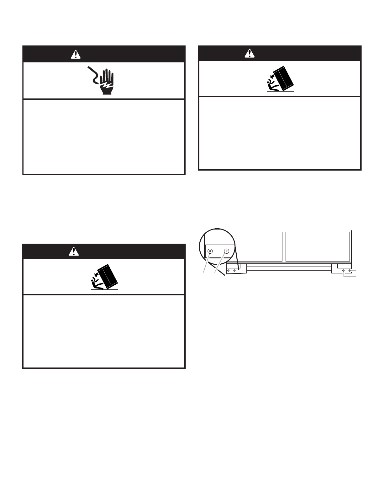
A B
A. Rear leveling bolt
B. Front leveling bolt
2. Adjust the leveling legs to level and align the refrigerator from
left to right and front to back so that the refrigerator is level
and aligned with the cabinetry. The cabinetry surface must be
plumb for the ideal t of the refrigerator side trim.
18
3. Continue adjusting all of the leveling legs to raise the
A
A
refrigerator until the top is within at least 1" (2.54 cm) of the
top soft.
NOTE: If an anti-tip board has been used, adjust the leveling
legs until the top of the refrigerator is within 1/4" (6.35 mm) of
the bottom of the anti-tip board as shown. Do not crush the
compressor cover.
BA
C
1/4" (6 mm)
max.
2" (5 cm)
D
A. Center board 1/4" (6.35 mm) max. above refrigerator
B. 2" x 4" x 32" (5 cm x 10 cm x 81 cm) boards (2)
C. Attach to studs with six #8 x 3" (7.6 cm) screws
D. Compressor cover
3. Remove the handle-side and top trims.
A
A. Trims
4. Slide the custom panels into the bottom and hinge side trims
on the refrigerator compartment and freezer compartment
doors, making sure that the backer panel ts into the hinge
side trims.
IMPORTANT: Adjust in small increments to keep from
damaging the cabinet trim and causing problems with the door
alignment or top grille t. To avoid damage to the cabinet or
leveling legs, do not apply more than 50 inch-pounds
(5.65 Nm) of torque to the leveling bolts. The leveling legs can
be extended to a maximum of 1¹⁄4" (3.18 cm) below the rollers.
4. For Overlay models, additional adjustments may be needed
after the custom panels are installed.
Install Overlay Series Custom Panels
IMPORTANT:
■ Install the custom handles prior to installing the panels on the
refrigerator. For more information on KitchenAid custom handle
selection, refer to the KitchenAid Catalog, visit
www.kitchenaid.com, or call 1-800-442-9991. In Canada,
visit www.kitchenaid.ca, or call 1-800-807-6777.
■ Create custom door overlay panels according to the
specications in the “Overlay Series Custom Panels” section.
■ KitchenAid is not responsible for the removal or addition of
molding or decorative panels that would not allow access to
the refrigerator for service.
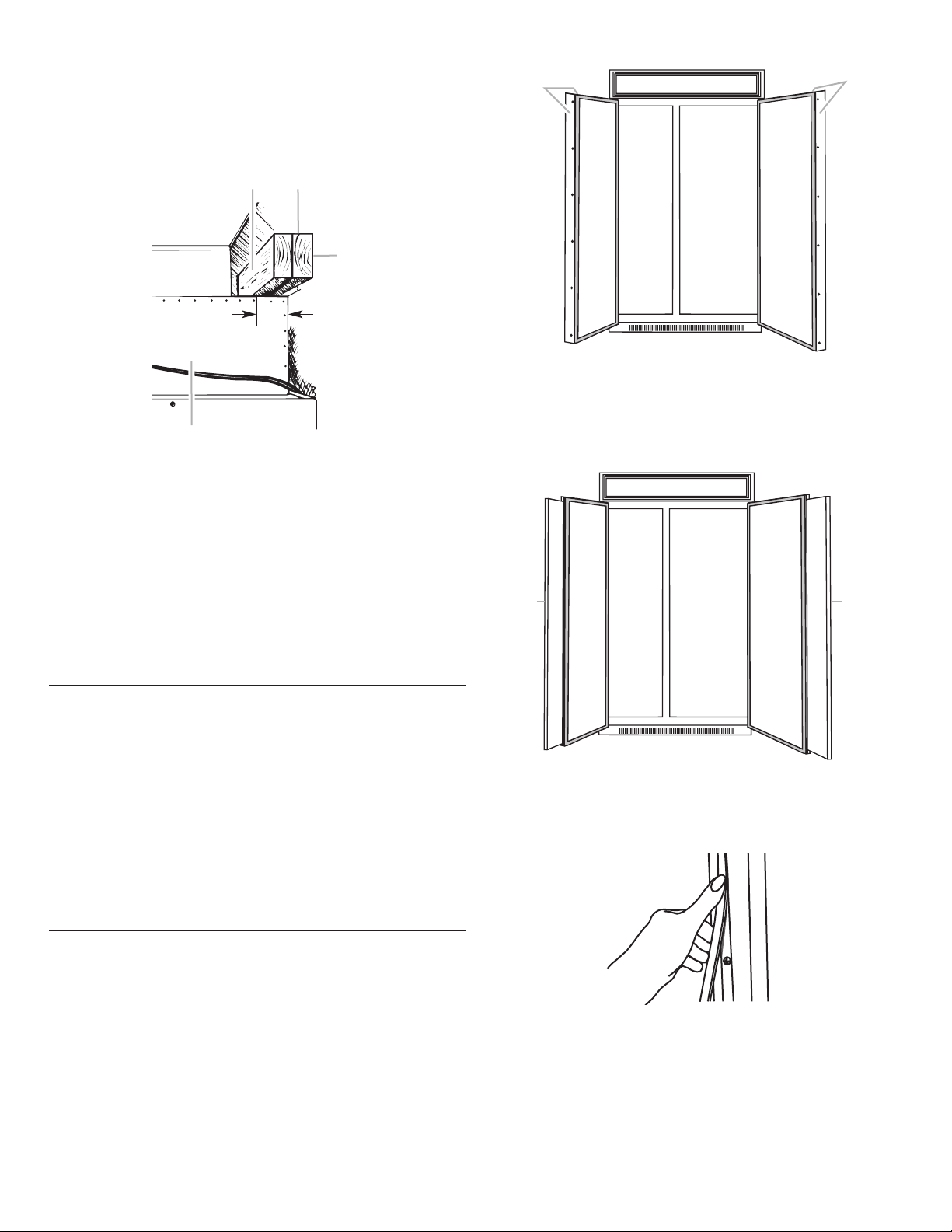
Door Panel Installation
1. Remove all tape and door bracing from the refrigerator and
freezer doors.
2. Open the refrigerator and freezer compartment doors.
A
A. Panels
5. Reinstall the handle-side and top trims.
6. Remove the skin from the screw covers. Slide or snap the
screw covers into the handle trim section.
7. Check refrigerator level and alignment. Adjust if needed.
19
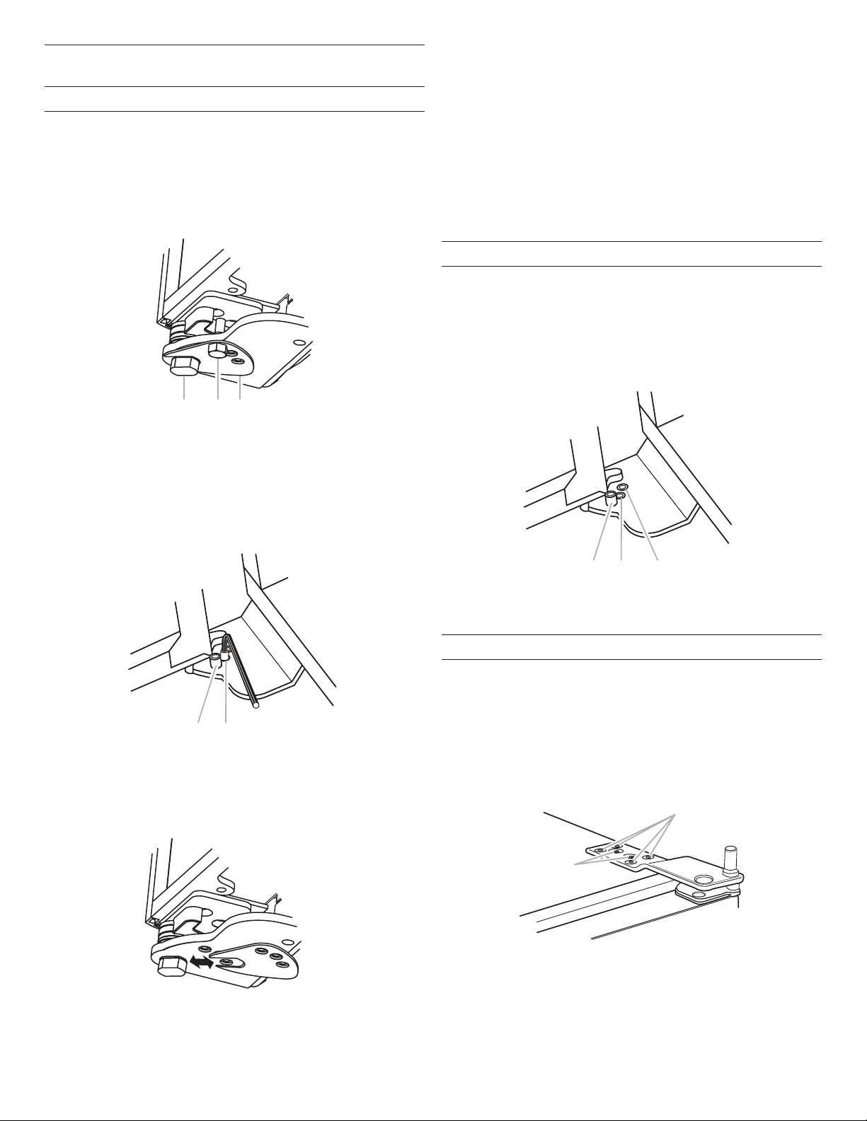
Adjust Doors
Door Height Adjustment
Use the following steps to adjust the door height, up or down,
after the doors have been leveled.
1. Open the freezer or refrigerator door. Locate the bottom hinge
and remove the door stop screw.
Stainless Models
Remove the door stop screw from the bottom side of the hinge
with a 3/8" open end wrench.
A BC
4. After adjusting, check the doors to make sure they are even at
the top and bottom. If the doors are not even, continue to turn
the bushing to adjust the door height.
5. Replace the locking plate.
6. Turn the bushing slightly to align the hinge and locking plate
screw holes.
7. Replace the door stop screw or screws and tighten.
IMPORTANT: Do not place the door stop screw in the 130°
position on Overlay Series models unless the custom panels
have been routed on the hinge side. See “Overlay Series Door
Panel and Cabinetry Clearance.”
8. Recheck to make sure the doors are aligned and even.
Door Swing Adjustment
1. Check that the refrigerator door can open freely. If the door
opens too wide, remove the door stop screw or screws
(depending on your model) from the bottom hinge. See “Door
Height Adjustment” earlier in this section.
2. Hold the door open to a position that is less than 90°.
3. Replace the door stop screw or screws in the bottom hinge
and tighten.
A. Bushing
B. Door stop screw
C. Locking plate
Overlay Models
Remove the 2 door stop screws: one from the bottom side
using a 3/8" open end wrench and one from the top side using
a 5/32" hex key.
AB
A. Door stop screw from bottom
B. Door stop screw from top (110°)
2. Remove the locking plate as shown.
AB C
A. 130°
B. 110° (Overlay series)
C. 90°
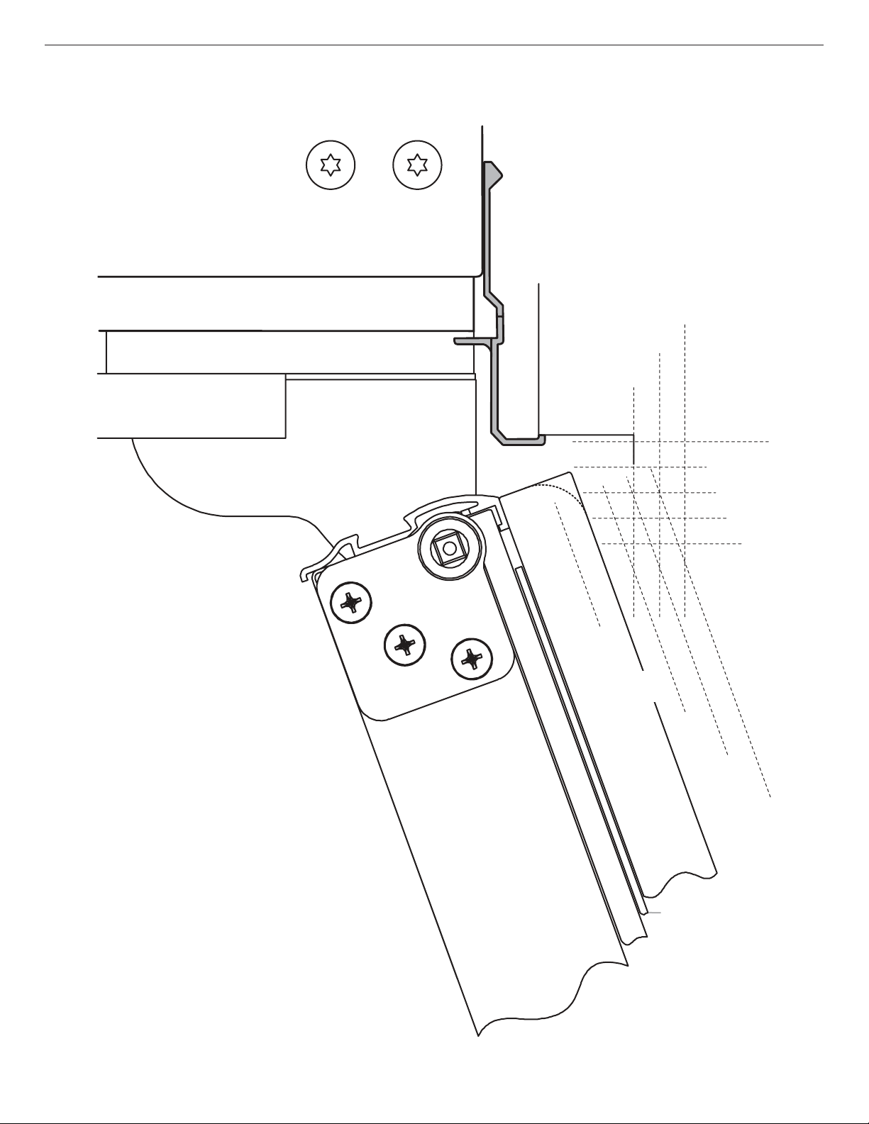
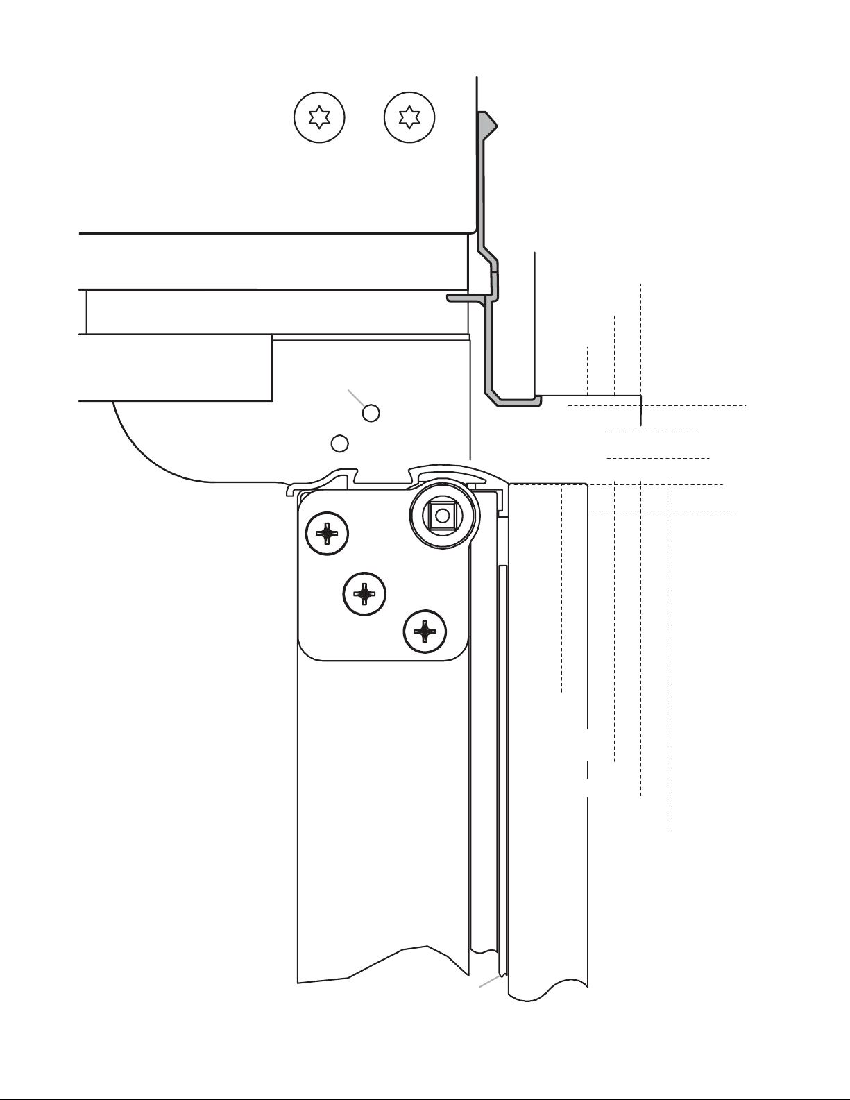
Door-to-Door or Door-to-Refrigerator Trim Adjustment
1. Loosen, but do not remove, the four Torx† 27 at-head
mounting screws. Remove and discard the two 1/4" hex-head
mounting screws.
2. Adjust the top hinge of either door to align it with the other
door or the refrigerator trim.
3. Tighten the four Torx† 27 at-head mounting screws to a
torque of approximately 100 inch-pounds (11.3 Nm).
A
3. Turn the bushing located underneath the bottom of the hinge
using a 1/2" open end wrench. Turning the bushing to the left
will lower the door. Turning the bushing right will raise the door.
†
TORX is a trademark of Acument Intellectual Properties, LLC
20
B
A. Torx 27 at-head mounting screws
B. 1/4" hex-head mounting screws
 Loading...