

Page 1
96050E
Setup software TM-H1
for the TM-3000 Series
TM-Navigator
User’s Manual
Read this manual before using the system in order to achieve
maximum performance.
Keep this manual in a safe place after reading it so that it can
be referenced at any time.
Page 2

Safety Precautions
This manual explains the functions, usage, and configurations for TM-H1 <TM-Navigator>, Setup software for the TM3000 Series. Read this manual carefully before starting to use the software to ensure the optimum performance and full
functionality of the <TM-Navigator>. Keep this manual in a safe place for future reference.
Read the TM-3000 Series User's Manual as well as this manual when using the <TM-Navigator>. The controller portion
of the TM-3000 Series is referred to as the "controller" in this manual.
Symbols
This manual indicates symbols as follows.
Reference
Provides advanced and useful information for operation.
Page 3

Contents
Contents
Chapter 1 Getting Started
System Environment ......................................... 1-2
Installing TM-Navigator ..................................... 1-2
Before Installation ........................................ 1-2
Installing TM-Navigator ............................... 1-3
Uninstalling TM-Navigator ........................... 1-3
Starting and Exiting TM-Navigator .................... 1-4
Start ............................................................. 1-4
Exit ............................................................... 1-6
Connecting via USB .......................................... 1-7
Connection Method ..................................... 1-7
Configuring Communication Settings ......... 1-7
Installing the USB Driver ............................. 1-8
Connecting via Ethernet ................................... 1-9
Connecting .................................................. 1-9
Configuring Communication Settings ......... 1-9
Chapter 2 Main Window
Main Window .................................................... 2-2
Part Names and Functions .......................... 2-2
Chapter 3 Operations with the Setting
Files
Reading and Saving Setting Files ..................... 3-2
Reading and Saving Program Files ............ 3-2
Reading and Saving Environment
Setting Files ........................................... 3-3
Sending and Receiving Settings ....................... 3-4
Sending All Settings .................................... 3-4
Receiving All Settings ................................. 3-4
Chapter 4 Displaying the Measure-
ment Data
View measurement value ..................................4-2
Functions and Display .................................4-2
View Image ........................................................4-5
Functions and Display .................................4-5
Functions and Usage of Re-measure
(Ref.Value) ...........................................4-10
Help:Ref.Value ...........................................4-11
How to Set Re-measure (Ref.Value) ..........4-11
Inspection Areas ........................................4-12
Data Storage ...................................................4-13
Functions and Display ...............................4-13
Image Storage .................................................4-19
Functions and Display ...............................4-19
How to Set Re-measure (Ref.Value) ..........4-24
Chapter 5 Setting Each Function
Setting Items ......................................................5-2
Head Settings ..............................................5-3
Position Correction .......................................5-9
Measurement Settings ...............................5-10
OUT Settings ..............................................5-11
Common Settings ......................................5-15
Setting List .................................................5-20
Environment Settings .......................................5-21
Setting Methods .........................................5-21
Appendix
USB Communication Failure .............................A-2
Excel File ...........................................................A-5
Excel Transfer Contents of Data Storage ....A-5
Error Messages .................................................A-6
Shortcut Key List ...............................................A-9
Software License Agreement ..........................A-10
Index ................................................................A-11
96050E
1
Page 4

Contents
MEMO
2
- Setup software TM-H1 TM-Navigator User’s Manual -
Page 5

Chapter
1
Getting Started
Getting Started
This chapter describes installing or uninstalling the TM-Navigator,
installing the USB driver, and connecting the controller to a computer.
System Environment . . . . . . . . . . . . . . . . . . . . . . . . . . . . . . .1-2
Installing TM-Navigator . . . . . . . . . . . . . . . . . . . . . . . . . . . . .1-2
Starting and Exiting TM-Navigator . . . . . . . . . . . . . . . . . . . .1-4
Connecting via USB. . . . . . . . . . . . . . . . . . . . . . . . . . . . . . . .1-7
Connecting via Ethernet . . . . . . . . . . . . . . . . . . . . . . . . . . . .1-9
- Setup software TM-H1 TM-Navigator User’s Manual -
1-1
Page 6

System Environment • Installing TM-Navigator
System Environment
Getting Started
The following computer environments are necessary to
use the TM-Navigator.
• CPU:
Pentium III 1GHz or more (1.7GHz or more
recommended)
• Supported OS:
Windows 7*
Windows Vista*
Windows XP Professional Edition/Home Edition
Windows 2000
• Memory capacity:
512MB or more (1GB or more recommended)
• Display:
XGA (1024 x 768 pixels) or greater, 256 colors or
greater
• Hard disk drive space:
1GB or more
• Interface*
Includes one of the following:
USB2.0/1.1*
* Use this software in recommended environments
according to your OS.
*1 Compatible with each edition of Home Premium,
Professional, Ultimate.
*2 Compatible with each edition of Ultimate, Business,
Home Premium and Home Basic.
*3 Select one for communication. Multiple interfaces
cannot be used for communication at the same time.
*4 Function is not guaranteed when connected through
a USB hub.
*5 Function is not guaranteed when connected through
a router or a LAN connection.
To use the Excel transmission function, install any of the
following applications in addition to the above
requirements.
Excel2007 / Excel2003 / Excel2002 / Excel2000
1
2
3
:
4
or Ethernet*
5
Installing TM-Navigator
This section describes how to install the TM-Navigator
and "USB driver" to a computer.
Before Installation
Check the following items before installing.
Reference
• We recommend making a backup of the master disc in
case the CD-ROM becomes damaged.
• Close all programs before installing.
User privileges
• For Windows XP/2000
When TM-Navigator is installed into the default folder
(C:\Program Files\Keyence\TM-Navigator\), set the
following access privileges.
Users must be given rights for “User” or greater in
order to use TM-Navigator.
• For Windows VISTA/7
When TM-Navigator is installed into the default folder
(C:\Program files\Keyence\TM-Navigator\), set the
following access privileges.
Users must be given rights for "User" or greater in
order to use TM-Navigator.
Free space on the hard disk
TM-Navigator can only be installed on a hard disk drive.
The hard disk drive where the software will be installed
must have at least 1GB of free space. If there is
insufficient free space, delete unnecessary items to
secure the free space.
Pre-installation Windows environment
TM-Navigator is a Windows application and the software
is installed in Windows. Check that Windows 7/Vista/XP/
2000 is installed on the computer and is working
properly.
1-2
- Setup software TM-H1 TM-Navigator User’s Manual -
Page 7

Installing TM-Navigator
Getting Started
Installing TM-Navigator
Reference
Log onto the computer as a user with "Administrator"
privileges for installation.
This section explains how to install TM-Navigator using
the following drive configuration as an example.
C Drive: Hard drive
E Drive: CD-ROM drive
Start up Windows and insert "TM-H1"
1
into the CD-ROM drive.
Select "Run..." from the Start menu.
2
Enter "e:\set up" into the [File name]
dialog box and click the [OK] button.
Follow the directions on the installation
3
program for installation.
Reference
• The driver necessary for the USB connection is
installed.
• TM-Navigator installation folder
When installing TM-Navigator with the default
settings, the program is installed into the following
folder:
C:\Program files\Keyence\TM-Navigator\
Uninstalling TM-Navigator
Reference
Log onto the computer as a user with "Administrator"
privileges for uninstallation.
Select Control Panel for the Start menu.
1
[Control Panel] appears.
Select Add or Remove Programs.
2
[Add or Remove Programs] window appears.
Select TM-Navigator from Currently
3
installed programs and click the
Remove button.
[Add or Remove Programs] window appears.
Click [Yes].
4
TM-Navigator is uninstalled from the computer.
- Setup software TM-H1 TM-Navigator User’s Manual -
1-3
Page 8
Starting and Exiting TM-Navigator
Starting and Exiting TM-Navigator
Getting Started
This section describes how to start and exit TM-Navigator.
Reference
• Multiple instances of TM-Navigator cannot be started
up at the same time.
• The USB and Ethernet interfaces on a single controller
cannot be used at the same time.
• Communication is disabled when the controller is in the
"Program mode".
Start
TM-Navigator starts up in one of the following methods:
• Start up with the default values
• Read from a file
• Read the settings of the connected controller
Click the [Start] button and then select
1
TM-Navigator, or double-click on the
TM-Navigator icon on the desktop.
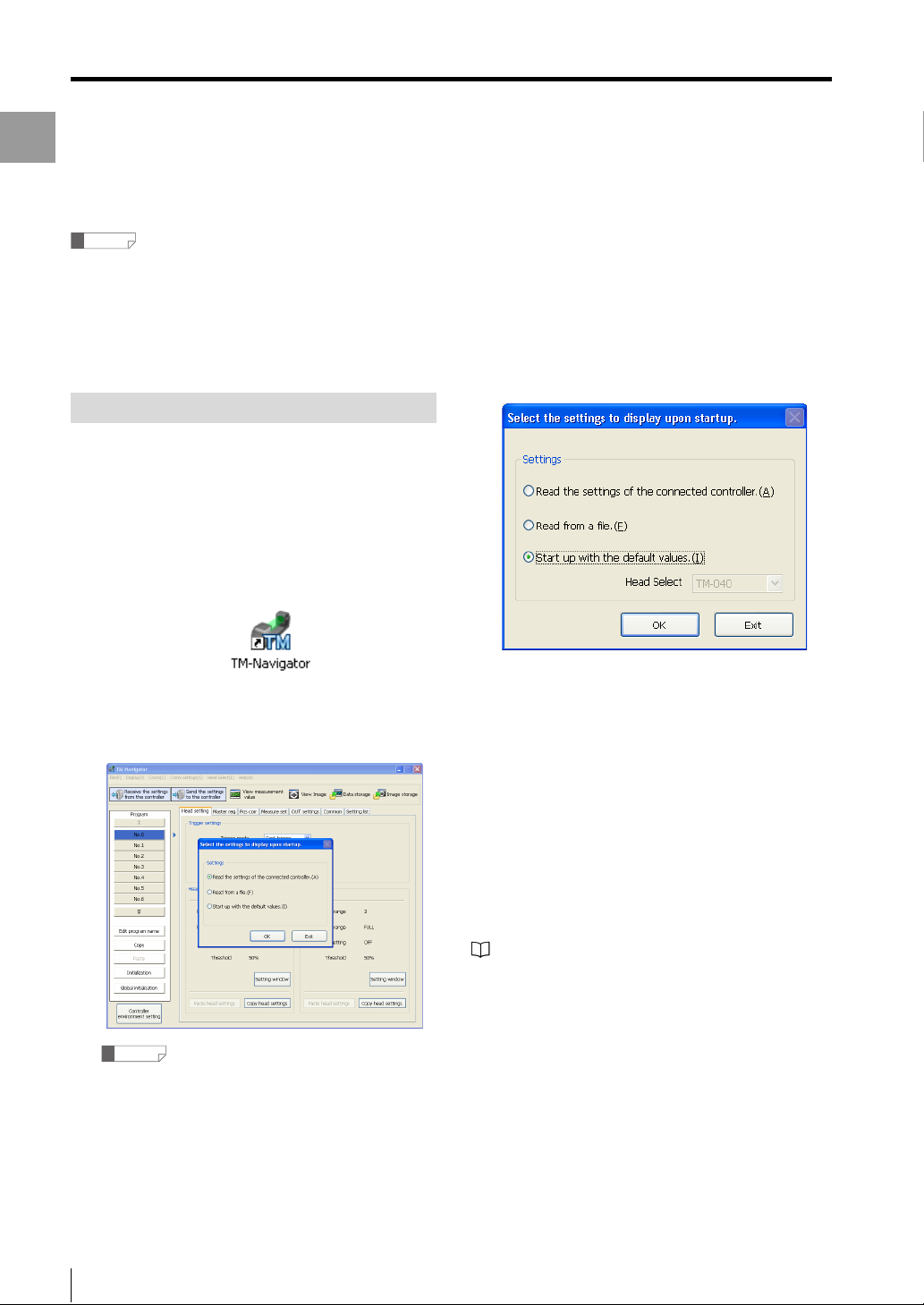
Step 2-1 When [Start up with the default values] is
selected
Select [Start up with the default values] the first time that
TM-Navigator is started up or when creating a new
program.
Use the following procedure to start up.
Select [Start up with the default values]
1
and click the [OK] button.
TM-Navigator starts up. The main screen and the
[Select the settings to display upon startup] dialog
box are displayed.
Reference
Click the [Exit] button to exit TM-Navigator.
Select the setting contents and press
2
the [OK] button.
TM-Navigator starts up with the default states for all
setting files.
The operation when [Start up with the default values] is
selected is determined based on whether the head data
has been saved on the hard disc drive of the computer or
not.
• If not registered (When using TM-Navigator for the first
time):
Select the head model to use from the pull-down menu
and start up.
• If registered:
The head data already recorded is used at start up. The
head model cannot be selected.
"Help:Ref.Value" (page 4-11)
1-4
- Setup software TM-H1 TM-Navigator User’s Manual -
Page 9
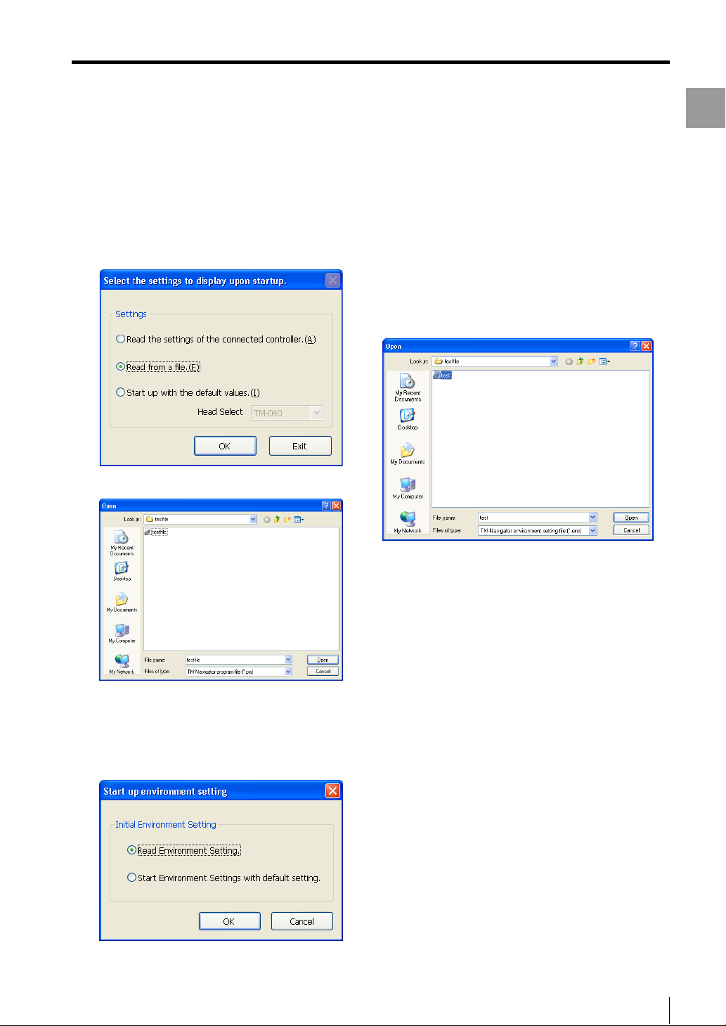
Step 2-2 When [Read from a file] is selected
When [Read from a file] is selected, TM-Navigator loads
a program file and an environment setting file that have
been saved on the computer.
Select [Read from a file] and click the
1
[OK] button.
Starting and Exiting TM-Navigator
Select [Read Environment Setting] or
3
select [Start Environment Settings with
default setting].
The operation procedure will differ depending on the
status that [Read Environment Setting] is selected
or [Start Environment Settings with default setting] is
selected.
(1) When [Read Environment Setting] is selected
Select the environment setting file (*.ens)and click the
[Open] button.
Getting Started
The [Open] dialog box appears.
Select a program file to read and click
2
the [Open] button.
The [Start up environment setting (2/2)] dialog
appears.
The environment setting file is read and TM-Navigator
starts up.
(2) [Start Environment Settings with default setting] is
selected
TM-Navigator starts up with the defaults for the
environment settings.
- Setup software TM-H1 TM-Navigator User’s Manual -
1-5
Page 10
Starting and Exiting TM-Navigator
Getting Started
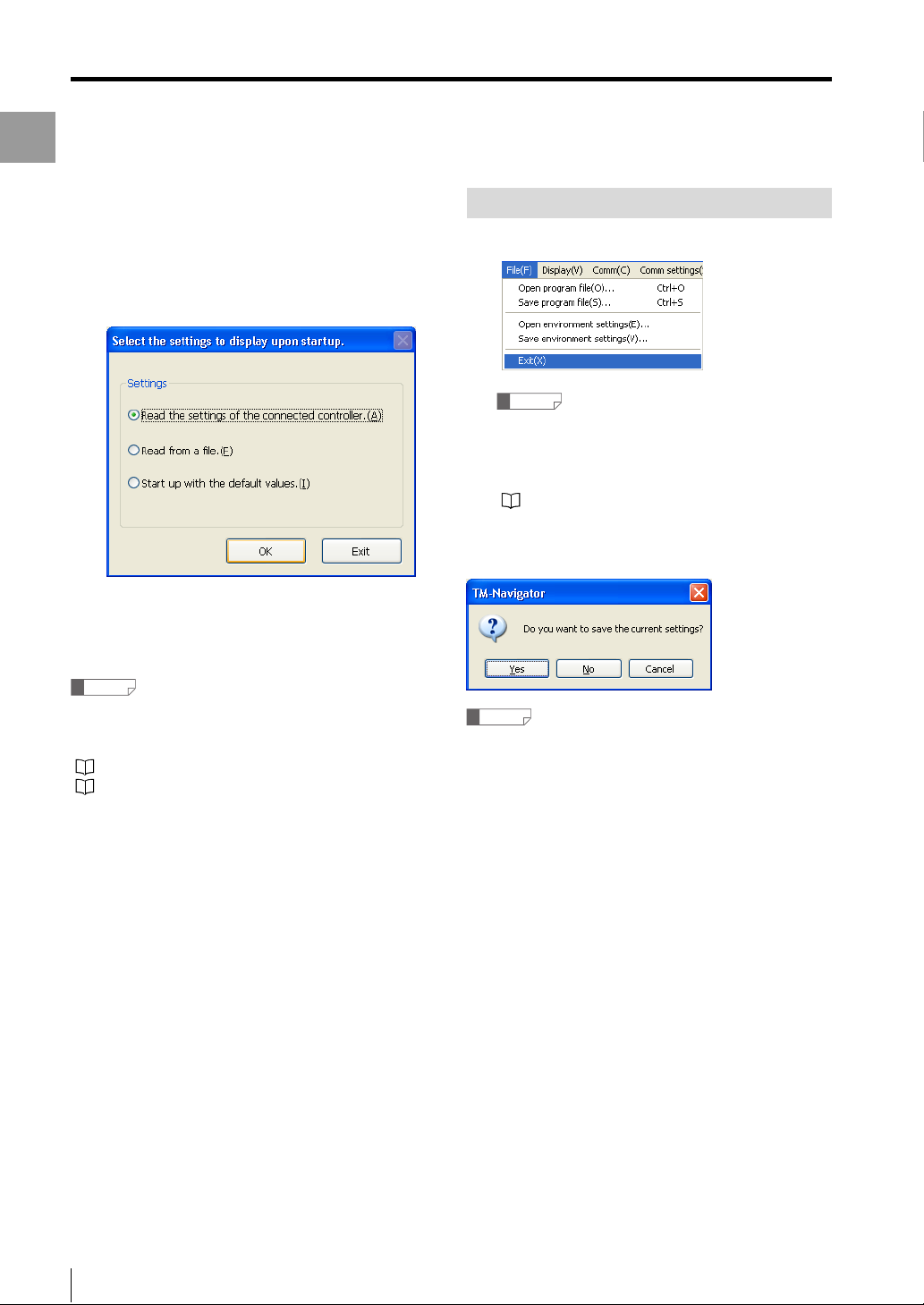
Step 2-3 When [Read the settings of the connected
controller] is selected
Select [Read the settings of the
1
connected controller] and click the
[OK] button.
Exit
Select [Exit] from the [File] menu.
1
Reference
If the settings have been changed, make sure to
save the program file and environment setting file
before exiting TM-Navigator. The changes will be
lost if the files are not saved before exiting.
"Reading and Saving Setting Files" (page 3-2)
If the settings have been changed, a confirmation
window appears.
The setting files (environment setting file and
program file) on the connected controller are read
and TM-Navigator starts up.
Reference
In order to read the controller settings, communication
must be established between the controller and
computer beforehand.
"Connecting via USB" (page 1-7)
"Connecting via Ethernet" (page 1-9)
Reference
If the [No] button is clicked, TM-Navigator exits without
saving the settings.
1-6
- Setup software TM-H1 TM-Navigator User’s Manual -
Page 11
Connecting via USB
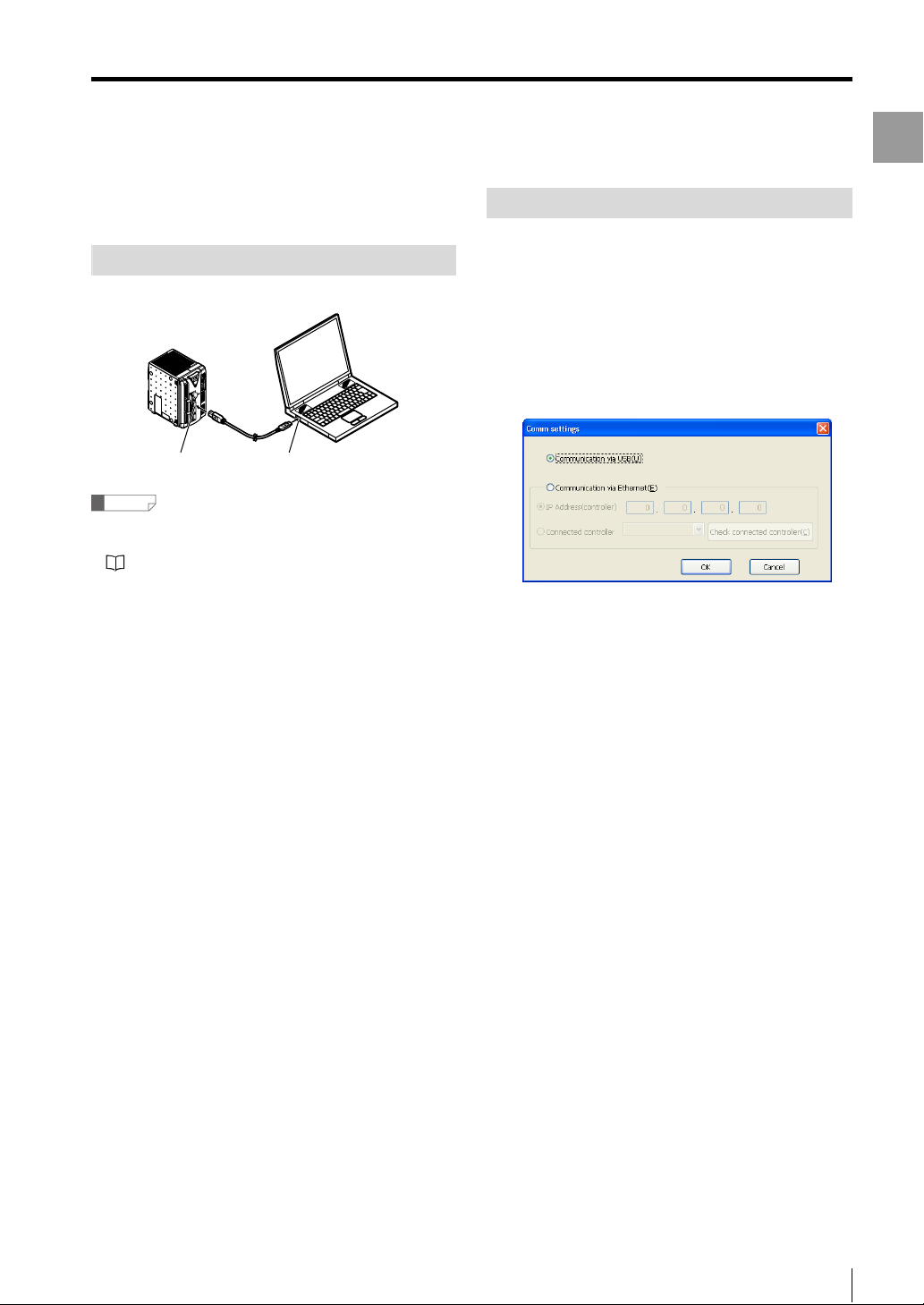
This section describes how to connect the controller to a
computer with a USB connection.
Connection Method
Use a USB cable (included).
LE
O
S
N
O
C
R
TO
I
N
3000
-
MO
TM
R
E
W
O
P
ON
/O
I
D
R
A
C
SD
B
EAD
H
T
OU
B
US
A
EADH
2C
RS-23
NET
R
E
ETH
USB connector USB port
Reference
• Install the USB driver when connecting the computer
and controller with the USB interface for the first time.
"Installing the USB Driver" (page 1-8)
• Do not remove the USB cable while the controller is
running. Otherwise, the controller may not function
correctly. If the communication is disabled due to
accidental disconnection of the USB cable, restart both
TM-Navigator and the controller.
Connecting via USB
Configuring Communication Settings
Start up TM-Navigator.
1
Select [PC communication setting]
2
from the [Comm settings] menu.
The [Comm settings] dialog appears.
Select [Communication via USB] from
3
the [Comm settings] dialog.
Getting Started
- Setup software TM-H1 TM-Navigator User’s Manual -
1-7
Page 12
Connecting via USB
Getting Started
Installing the USB Driver
The driver is installed at the same time as the application
software for Windows 7, Vista, XP, and 2000. Normally
following operations are not necessary.
If the driver installation is cancelled while installing the
application software, follow the procedure below to
manually install the USB driver.
Installing on Windows XP
Connect the controller to a computer with Windows XP. If
the controller is being connected for the first time, the
USB driver for the TM-3000 Series must be installed. The
connection is automatically recognized after the USB
driver has been installed once and does not need to be
installed again.
This section explains how to install the driver for the TM3000 Series on a computer with Windows XP for the first
time.
Hardware detection must be performed when installing
the USB driver for the TM-3000 Series.
Use the following methods to install the driver.
Start up Windows XP and log in as a
1
user that has Administrator privileges
(or similar privileges that permit
changing system settings).
Connect the USB port on the computer
2
with the USB port on the TM-3000
Series controller using the USB cable.
The message "Found New Hardware" appears and
the Hardware Update Wizard starts up.
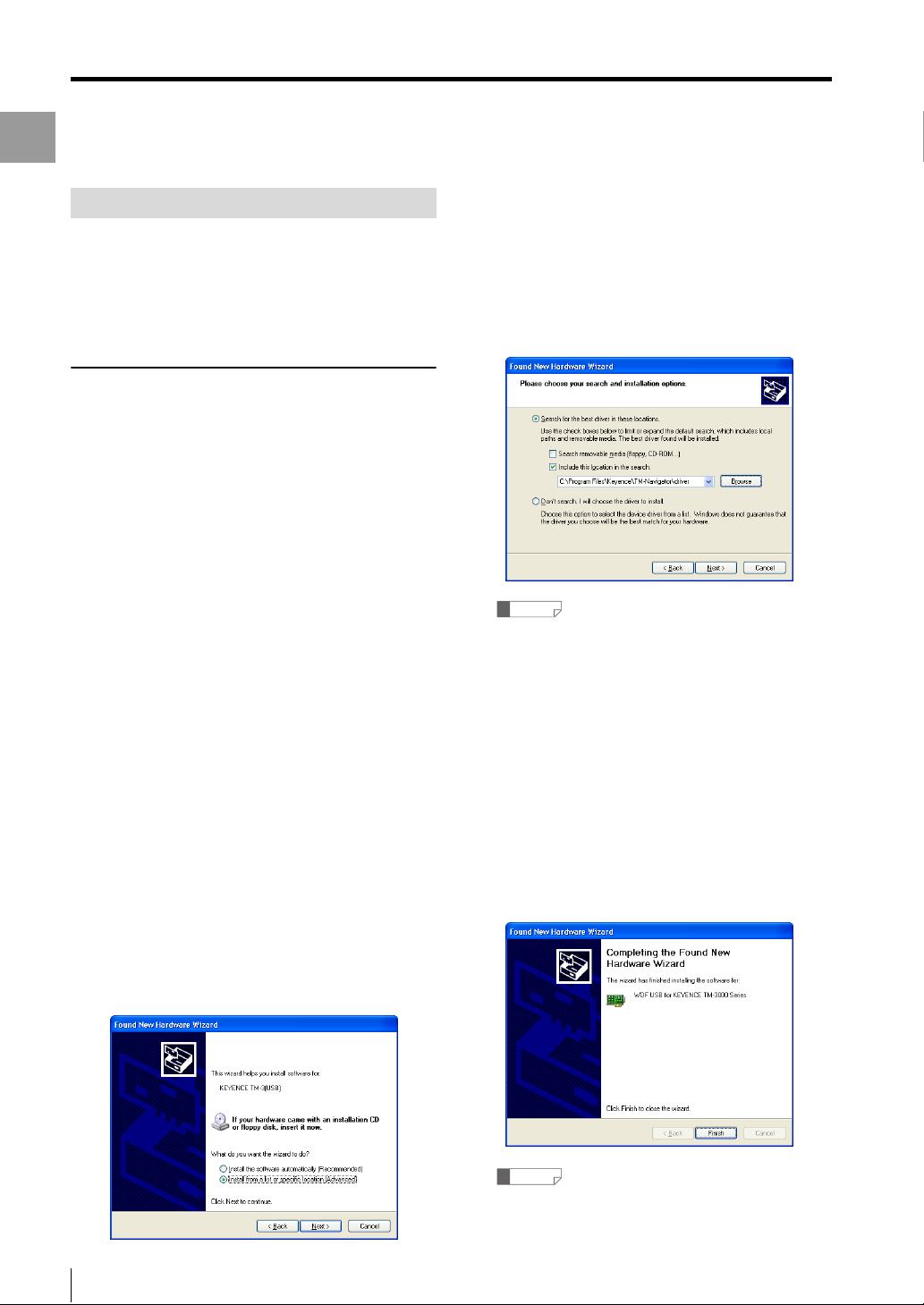
Select [Search for the best driver in
4
these locations.] and check the box
next to [Include this location in the
search:].
Then, enter "C:\Program Files\KEYENCE\TMNavigator\driver" in the text box and click the [Next]
button.
Reference
"C:\Program Files\KEYENCE\TM-Navigator\driver"
represents the location where TM-Navigator will be
installed.
Change the location depending on the system
environment.
Continue installation according to the
5
on-screen instructions.
When installation of the USB driver ends
successfully, the [Completing the Hardware Update
Wizard] dialog appears.
Click the [Finish] button to complete
6
installation of the USB driver.
Select [Install from a list or specific
3
location (Advanced)], and click the
[Next] button.
1-8
- Setup software TM-H1 TM-Navigator User’s Manual -
Reference
When installing onto a computer with Windows 2000,
install the USB driver according to the wizard.
Page 13
Connecting via Ethernet
This section describes how to connect the controller to a
computer with an Ethernet connection. When using Ethernet
communication, one computer can be connected to multiple
controllers. One of the connected controllers can be selected
for communication. The communication protocol is TCP / IP,
while the connection uses peer-to-peer communication.
Reference
• Configure the settings so that there are different IP
addresses used for the computer and each controller
on the network.
• function is not guaranteed when connected through a
router or a separate LAN connection.
• One computer cannot communicate with multiple
controllers at the same time.
Multiple computers cannot be connected to one controller.
•
•
Do not set 0.0.0.0 or 255.255.255.255 for the IP address.
Connecting
Connecting via Ethernet
Getting Started
Configuring Communication Settings
Set the following communication settings when
communicating with Ethernet.
• IP address
Configure unique addresses for the computer and each
controller. Do not set 0.0.0.0 or 255.255.255.255 for the
IP address.
Ex.: When using two controllers and one computer
Controller No. 1 192.168.0.10
Controller No. 2 192.168.0.11
Computer 192.168.0.12
• Subnet mask
Configure the same settings on the computer and
controllers. Use the default value normally.
(Default: 255.255.255.0)
• Default gateway
Use the default value normally.
(Default: 0.0.0.0)
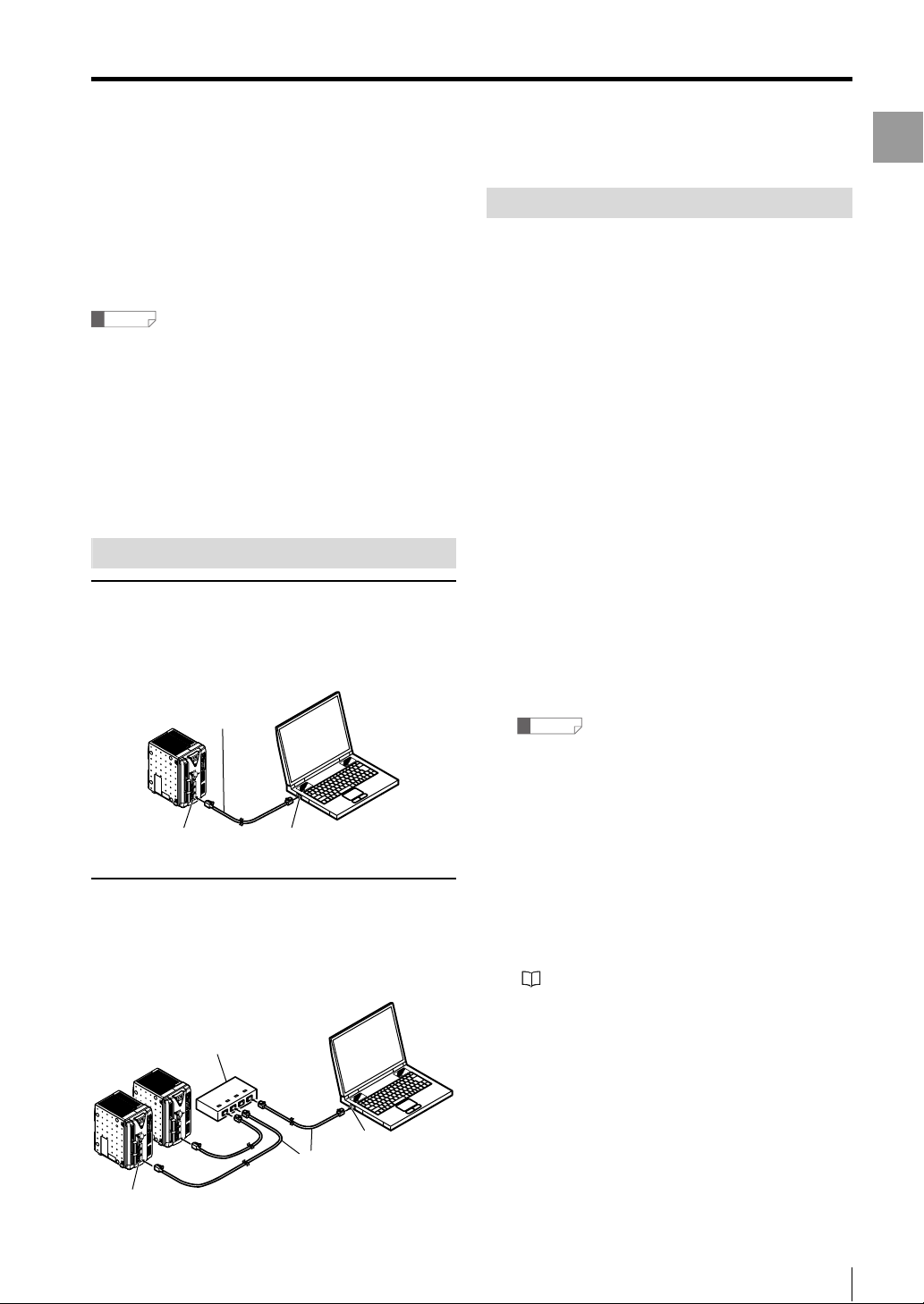
Connecting one controller directly to one
computer
Use a commercial Ethernet cross cable (*) for connection.
* Use cables supporting the communication speed.
Cross cable
LE
O
S
N
O
C
MONITOR
TM-3000
R
E
OW
P
N
O
/O
I
D
R
A
C
SD
HEAD-B
T
U
O
USB
A
HEAD-
RS-232C
ETHERNET
Ethernet connector Ethernet port
Connecting to two or more controllers
A 1000BASE-T / 100BASE-TX / 10BASE-T hub is required
to connect to two or more controllers. Use commercial
Ethernet straight cables to connect between the hub and
the computer or controllers.
Hub
LE
O
S
N
O
C
R
MONITO
TM-3000
R
E
W
O
P
ON
I/O
D
R
A
DC
S
HEAD-B
E
L
O
S
N
O
C
OUT
USB
TOR
MONI
TM-3000
R
HEAD-A
WE
O
P
N
O
I/O
RS-232C
D
ET
SDCAR
ETHERN
HEAD-B
OUT
USB
HEAD-A
RS-232C
ETHERNET
Straight cable
Ethernet port
Set the Ethernet settings for the
1
controller.
Set the IP address, subnet mask, and default
gateway.
For more information about configuring settings, see
"TM-3000 Series User's Manual".
Reference
Restart all of the controllers after configuring the
settings to activate the changes to the Ethernet
settings.
Set the Ethernet settings (TCP / IP) for
2
the computer.
The method for configuring the settings depends on
the version of Windows. For more details, see the
instruction manual for the computer or LAN card.
Starts up TM-Navigator.
3
"Starting and Exiting TM-Navigator" (page 1-4)
Select [PC communication setting]
4
from the [Comm settings] menu.
The [Comm settings] dialog appears.
Ethernet connector
- Setup software TM-H1 TM-Navigator User’s Manual -
1-9
Page 14
Connecting via Ethernet
Getting Started
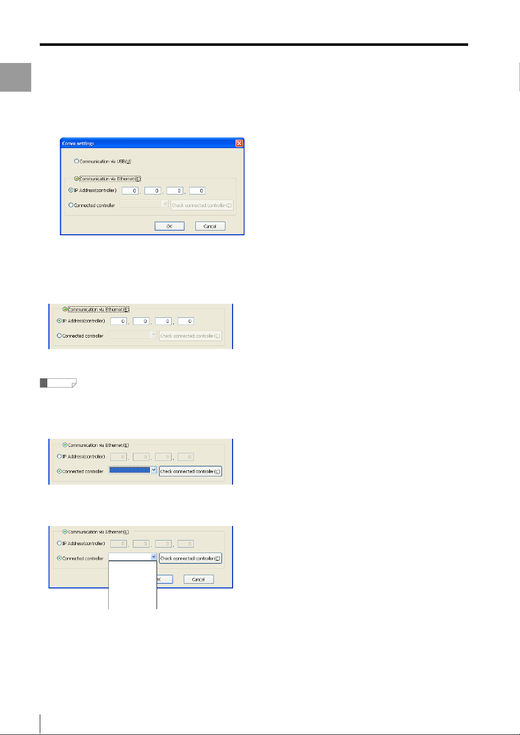
Select [Communication via Ethernet]
5
from the [Comm settings] dialog.
To enter the IP address for the connected controller
directly
Select [IP address (controller)] and enter the IP address
for the connected controller.
To search for the connected controller and specify
Reference
Turn the controller on beforehand and check that it is
communicating properly.
(1) Select [Connected controller] and click the [Check
connected controller] button.
(2) Search for the connected controller automatically. The
detected IP address is displayed on the pull-down
menu. Then, select the controller for communication.
192.168.0.10
192.168.0.11
192.168.0.13
Click the [OK] button.
6
The [Comm settings] dialog is closed.
1-10
- Setup software TM-H1 TM-Navigator User’s Manual -
Page 15

Chapter
2
Main Window
Main Window
This chapter describes the names and functions of each part of the
TM-Navigator main window and how to operate them.
Main Window . . . . . . . . . . . . . . . . . . . . . . . . . . . . . . . . . . . . .2-2
- Setup software TM-H1 TM-Navigator User’s Manual -
2-1
Page 16
Main Window
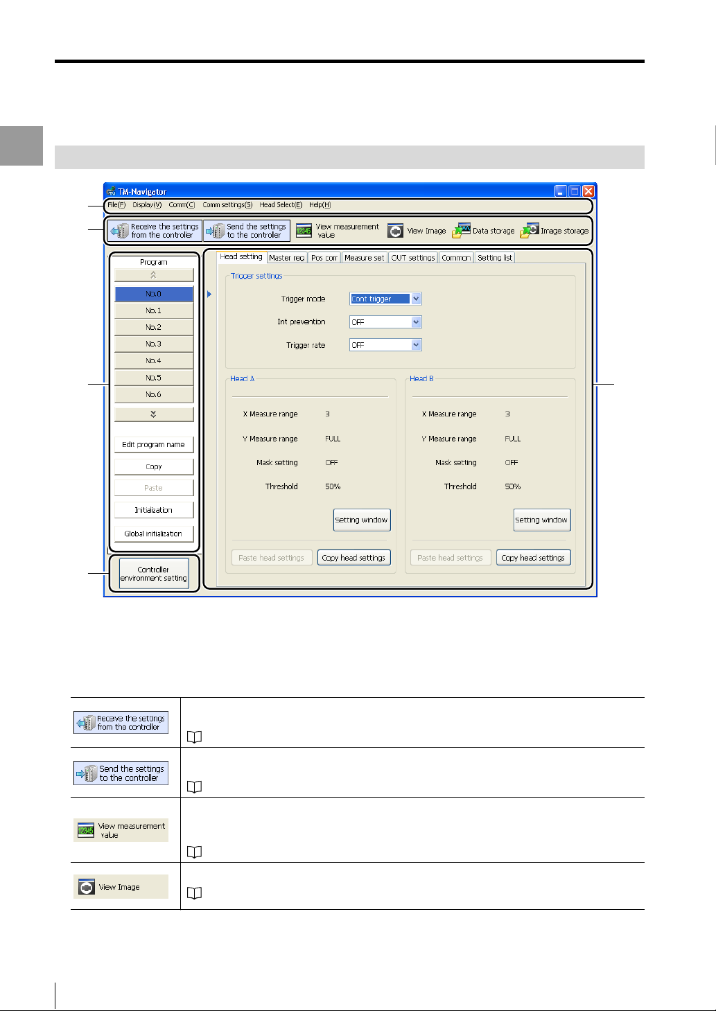
Main Window
Part Names and Functions
Main Window
(1)
(2)
(3)
(4)
(1) Menu bar
Displays the operational menus for TM-Navigator.
(2) Tool bar
Displays the buttons for frequently used menus, such as the displays for measurement values and communication
with the controller.
TM-Navigator reads the setting data (program file and environment setting file) that is saved
in the controller.
"Receiving All Settings" (page 3-4)
TM-Navigator writes changed setting data (program file and environment setting file) to the
controller.
"Sending All Settings" (page 3-4)
Displays the value measured by the head on TM-Navigator.
Clicking [Measurement value acquisition start] button displays and updates the
measurement data.
"View measurement value" (page 4-2)
(5)
2-2
Displays the image viewed by the head on TM-Navigator.
"View Image" (page 4-5)
- Setup software TM-H1 TM-Navigator User’s Manual -
Page 17
Main Window
Configures the settings for storing measurement data in the controller.
Stored data can be displayed on TM-Navigator or saved as a file on the computer.
"Data Storage" (page 4-13)
Configures the settings for storing measured image data in the controller.
Stored image data can be displayed on TM-Navigator or saved as a file on the computer.
"Image Storage" (page 4-19)
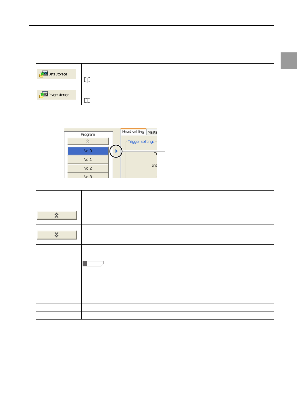
(3) Setting and operation area for program settings
Switches the program No. of which the setting will be changed.
No. 0 to 15
The settings for the selected program No. can be checked and changed. (Program No.)
Clicking on the selected program No. changes the color of the button to blue.
Clicking on this button displays the preceding program No.
Main Window
The currently displayed program
No. is shown.
Clicking on this button displays the following program No.
Clicking on this button displays the [Edit program name] dialog. Set the program name in this
dialog box.
Edit program name
Reference
• Enter up to 16 characters for the program name.
• Letters and numbers can be used for the program name.
Copy Copies the settings* in the currently selected program No. for pasting.
Paste
Pastes the settings* that were copied by using the [Copy] button into the program No. that is
being edited.
Initialization Initializes the settings* in the currently selected program No.
Global initialization Initializes the settings* for all of the program No. 0 to 15.
* "Copy", "Paste", and "Initialization" act on the following settings:
• Head Settings
• Master Registration (including the master image)
• Position Correction
• Measurement Settings
• OUT Settings
• Common Settings
- Setup software TM-H1 TM-Navigator User’s Manual -
2-3
Page 18

Main Window
(4) Controller environment setting
Configures settings such as communication conditions for the controller.
Main Window
"Environment Settings" (page 5-21)
(5) Program setting area
Sets the measurement conditions for each program. The tabs toggle between each setting.
• Head Settings ................."Head Settings" (page 5-3)
• Master Registration........."Master registration" (page 5-6)
• Position Correction.......... "Position Correction" (page 5-9)
• Measurement Settings .... "Measurement Settings" (page 5-10)
• OUT Settings................... "OUT Settings" (page 5-11)
• Common Settings ..........."Common Settings" (page 5-15)
• Setting List ......................"Setting List" (page 5-20)
Reference
For more information about each setting, see "TM-3000 Series User's Manual".
2-4
- Setup software TM-H1 TM-Navigator User’s Manual -
Page 19

Chapter
3
Operations with the Setting Files
Operations with the Setting Files
This chapter describes receiving, loading, saving, and sending
setting files.
Reading and Saving Setting Files . . . . . . . . . . . . . . . . . . . .3-2
Sending and Receiving Settings . . . . . . . . . . . . . . . . . . . . .3-4
- Setup software TM-H1 TM-Navigator User’s Manual -
3-1
Page 20
Reading and Saving Setting Files
Reading and Saving Setting Files
There are two types of setting files used by TM-Navigator:
Program files (*.prs)
Environment setting files (*.ens)
This section describes how to read setting files from the
Operations with the Setting Files
computer and save files to the computer.
Reference
• Program files include all of the settings in program No. 0
to 15.
• Program files and environment setting files are
managed separately.
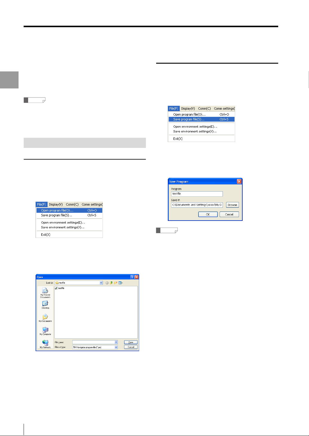
Reading and Saving Program Files
Reading program files
Select [Open program file] from the
1
[File] menu.
The [Open] dialog appears.
Select a program file (*.prs) to read and
2
click the [Open] button.
The program file is read.
Saving program files
Select [Save program file] from the
1
[File] menu.
The [Save] dialog appears.
Enter a program name and click on the
2
[Save] button.
The program file is saved.
Reference
• If a previously saved program file exists with the same
name, the file is overwritten.
• When a master image is registered in the saved
program file, the master registration image is saved in
the BMP format (extension: .bmp).
3-2
- Setup software TM-H1 TM-Navigator User’s Manual -
Page 21

Reading and Saving Setting Files
Reading and Saving Environment Setting Files
Reading environment setting files
Select [Open environment settings]
1
from the [File] menu.
The [Open] dialog appears.
Select an environment setting file
2
(*.ens) to read and click the [Open]
button.
The environment setting file is read.
Saving environment setting files
Select [Save environment settings] from
1
the [File] menu.
Enter a file name and click on the
2
[Save] button.
The environment setting file is saved.
Operations with the Setting Files
Reference
If a previously saved environment setting file exists with
the same name, the file is overwritten.
- Setup software TM-H1 TM-Navigator User’s Manual -
3-3
Page 22
Sending and Receiving Settings
Sending and Receiving Settings
This section describes how to transmit all settings
between TM-Navigator and the controller.
Settings that are changed in TM-Navigator are updated
to the controller immediately after being sent. Settings
Operations with the Setting Files
from the controller are reflected to TM-Navigator
immediately after being received.
This function transmits the following data to the controller.
• All of the settings for program No. 0 to 15 (Head
settings, Master registration, Position correction,
Measurement settings, OUT settings, Common
settings)
• Controller environment settings
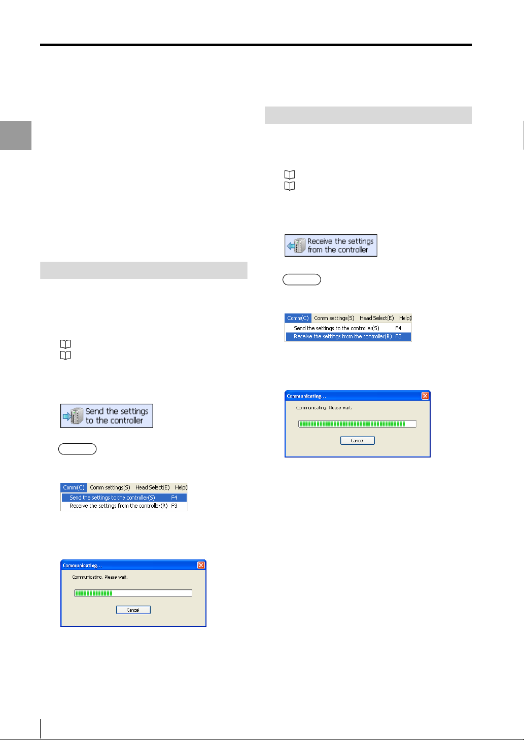
Sending All Settings
Connect TM-Navigator and the
1
controller, and check that
communication is normal.
"Connecting via USB" (page 1-7)
"Connecting via Ethernet" (page 1-9)
Click the [Send settings to controller]
2
icon on the tool bar.
Receiving All Settings
Connect TM-Navigator and the controller,
1
and check that communication is normal.
"Connecting via USB" (page 1-7)
"Connecting via Ethernet" (page 1-9)
Click the [Receive settings from
2
controller] icon of the tool bar.
Alternative
Select [Receive the settings from the controller] from
the [Comm] menu.
The [Communicating] dialog appears.
The dialog closes when receiving the settings is
complete.
Alternative
Select [Send the settings to the controller] from the
[Comm] menu.
The [Communicating] dialog appears.
The dialog closes when sending the settings is
complete.
3-4
- Setup software TM-H1 TM-Navigator User’s Manual -
Page 23

Chapter
4
Displaying the Measurement Data
Displaying the Measurement Data
This chapter describes how to display and operate the view
measurement value screen.
View measurement value. . . . . . . . . . . . . . . . . . . . . . . . . . . .4-2
View Image . . . . . . . . . . . . . . . . . . . . . . . . . . . . . . . . . . . . . . .4-5
Data Storage . . . . . . . . . . . . . . . . . . . . . . . . . . . . . . . . . . . . .4-13
Image Storage . . . . . . . . . . . . . . . . . . . . . . . . . . . . . . . . . . .4-19
- Setup software TM-H1 TM-Navigator User’s Manual -
4-1
Page 24
View measurement value
View measurement value
This section describes displaying the values measured with the controller in real time on the TM-Navigator.
Functions and Display
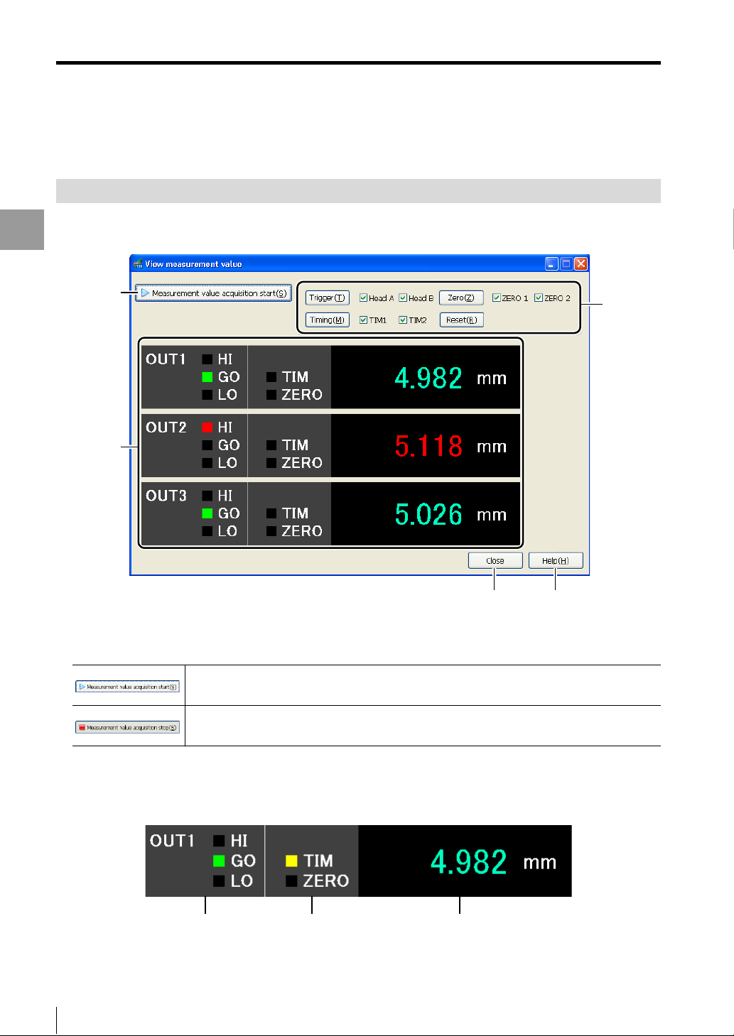
The values measured by the controller can be displayed in real time in the [View measurement value] window.
Measurement controls to the controller such as a trigger and timing input can also be performed.
Displaying the Measurement Data
(1)
(2)
(1) [Measurement value acquisition start] button
Displays the values being measured by the controller in real time on TM-Navigator.
Displayed while the measurement value acquisition is stopped. Click this button to start
receiving measurement values.
(3)
(4) (5)
Displayed while the measurement values are being received. Click this button during
measurement to stop receiving the values.
(2) View measurement value
Displays the measurement result from the controller for each OUT setting.
The values for all of the OUT settings (OUT1 to OUT16) that are set on the controller are displayed.
Tolerance evaluation output Timing/Zero display Measurement value
4-2
- Setup software TM-H1 TM-Navigator User’s Manual -
Page 25

(3) Measurement control
Inputs a control signal into the connected controller.
Inputs a trigger to the specified head.
: When inputting a trigger to only Head A
: When inputting a trigger to only Head B
: When inputting a trigger to both Head A and Head B
Inputs a TIMING input to the specified TIM.
Assign the TIMING input for each OUT setting by using the [Common] tab.
: When inputting TIMING on only TIM1
: When inputting TIMING on only TIM2
: When inputting TIMING on both TIM1 and TIM2
Inputs an auto-zero for the specified ZERO.
Assign the ZERO input for each OUT setting by using the [Common] tab.
: When inputting auto-zero on only ZERO1
View measurement value
Displaying the Measurement Data
: When inputting auto-zero on only ZERO2
: When inputting auto-zero on both ZERO1 and ZERO2
Resets the measured values that are displayed.
For more information about each control signal, see "TM-3000 Series User's Manual".
(4) [Close] button
Closes the [View measurement value] window.
(5) [Help] button
Opens the help menu for TM-Navigator.
- Setup software TM-H1 TM-Navigator User’s Manual -
4-3
Page 26
View measurement value
Operating the [View measurement value]
window
Connect TM-Navigator and the
1
controller, check that communication
Displaying the Measurement Data
can be established, and then measure
the target.
"Connecting via USB" (page 1-7)
"Connecting via Ethernet" (page 1-9)
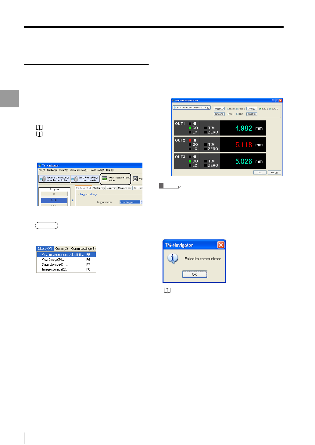
Click the [View measurement value]
2
icon on the tool bar.
The [View measurement value] window appears.
Alternative
• Select [View measurement value] from the
[Display] menu.
Click the [Measurement value acquisition
3
start] button.
The measurements for the OUT settings that are
configured in the controller appear in the window.
Reference
• If communication is not possible between TM-Navigator
and the controller, or if a head is not connected, the
following dialog appears shortly after clicking the
[Measurement value acquisition start] button or
[Trigger] button.
Check the connection between each head and
between TM-Navigator and the controller.
• Press the "F-5" key.
4-4
For more information about the OUT settings, see
"TM-3000 Series User's Manual".
- Setup software TM-H1 TM-Navigator User’s Manual -
Page 27

View Image
View Image
This section describes displaying images that are being measured with the controller in real time on the TM-Navigator.
Functions and Display
The images measured by the controller can be displayed in real time in the [View Image] window.
(1) (2) (3) (4) (5) (6)
Displaying the Measurement Data
(7)
(8)
(9)
(10)
(11) (12) (13) (14) (15)
(1) [Start image capturing] button
Displays the images being measured by the controller in real time on TM-Navigator.
Displayed while the image capturing is stopped. Clicking the button starts capturing the
image being measured by the controller into TM-Navigator.
Displayed while the image capturing is proceeding. Image capturing is stopped by clicking
this button while capturing.
- Setup software TM-H1 TM-Navigator User’s Manual -
4-5
Page 28
View Image
(2) [Re-measure (Ref.Value)] button
This function changes or confirms the measurement settings using saved images.
The confirmed setting conditions can be saved and sent to the controller.
"Functions and Usage of Re-measure (Ref.Value)" (page 4-10)
(3) [Help:Ref.Value] button
The help file for Re-measure (Ref.Value) is displayed.
Displaying the Measurement Data
(4) [Excel transfer start] button
By clicking this button, the function to collect values being currently measured into Excel is set to ON.
(5) [Excel transfer] button
When the [Excel transfer] button is clicked with the [Excel transfer start] button pressed down, the currently
measured value is added to the cell on the Excel.
(6) [Trigger] button
Inputs a trigger to the selected head.
For more information about triggers, see "TM-3000 Series User's Manual".
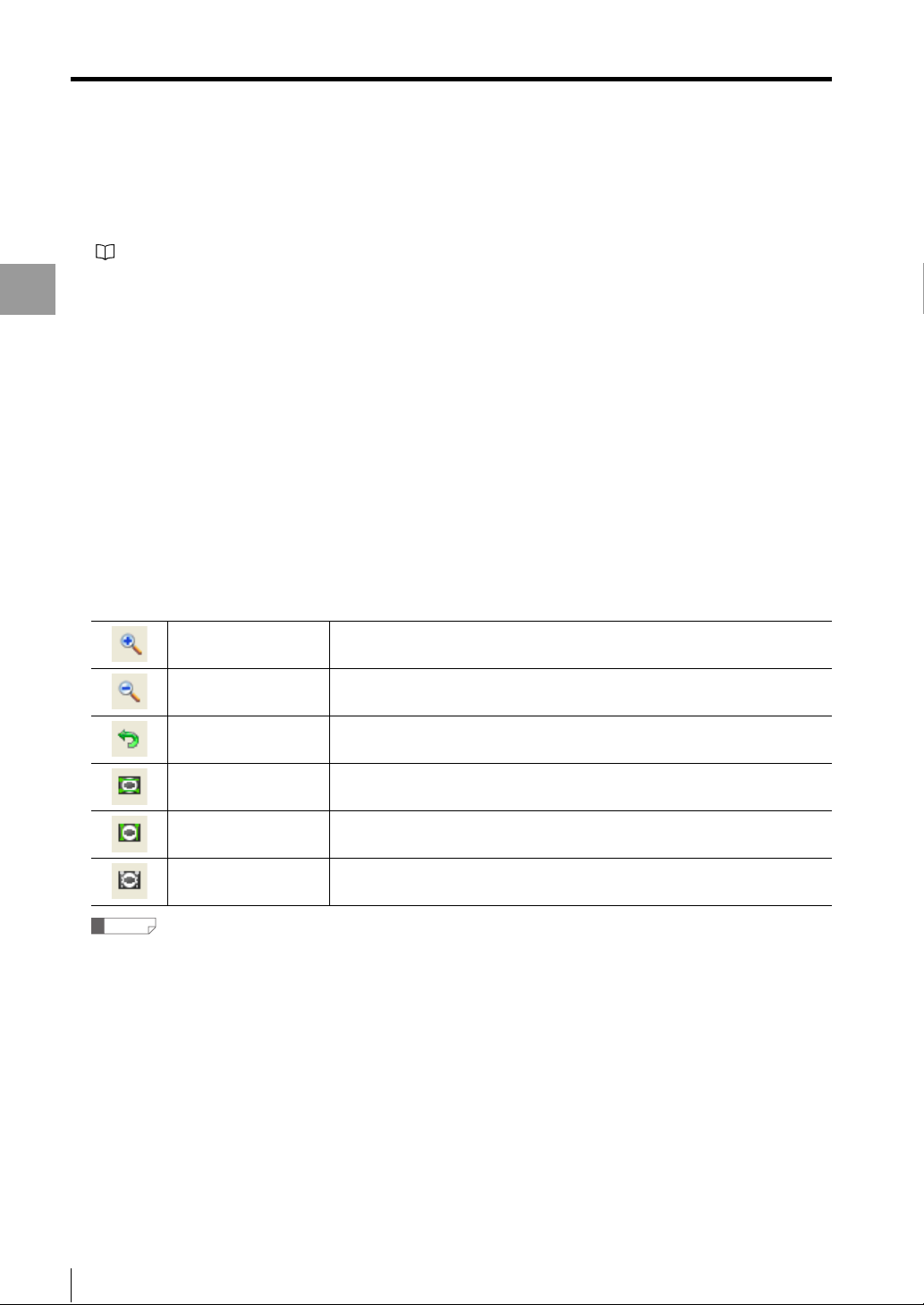
(7) Display setting menu bar
Performs operations on the displayed image.
When two screens (left: Head A, right: Head B) are displayed, this operation is possible for each display.
Zoom in This button zooms in the displayed image.
Zoom out This button zooms out the displayed image.
Default display This button returns the displayed image to the default display size.
Horizontal cursor This button displays the horizontal cursors on the view image area.
Vertical cursor This button displays the vertical cursors on the view image area.
Hide the cursor This button hides the cursors.
Reference
When the view area is zoomed in, it is possible to pan the field of view by dragging in the image area.
(8) View image area
This displays the image obtained from the controller or the image saved on the computer.
(9) Display setting
Select the head to display on the view image area.
4-6
- Setup software TM-H1 TM-Navigator User’s Manual -
Page 29

(10)
View measurement value area
This displays the measurement value in each OUT number.
(11)
[Save image] button
The image in the view image area is saved as a file in BMP format.
Reference
The cursor is not saved.
(12)
[Read image] button
This displays the saved image in the view image area.
(13)
[Cursor information] area
This displays the position information of the cursor displayed in the view image area.
(14)
[Close] button
This closes the [View Image] window.
(15)
[Help] button
Opens the help menu for TM-Navigator.
View Image
Displaying the Measurement Data
- Setup software TM-H1 TM-Navigator User’s Manual -
4-7
Page 30

View Image
Displaying the [View Image] window
Connect TM-Navigator and the
1
controller, check that communication
can be established, and then measure
Displaying the Measurement Data
the measurement target.
"Connecting via USB" (page 1-7)
"Connecting via Ethernet" (page 1-9)
Click the [View Image] icon on the tool
2
bar.
The [View Image] window appears.
Alternative
• Select [View Image] from the [Display] menu.
Updating the image display
This updates the image displayed on TM-Navigator to the
latest image data in the controller.
Connect TM-Navigator and the
1
controller, check that communication
can be established, and then measure
the measurement target.
"Connecting via USB" (page 1-7)
"Connecting via Ethernet" (page 1-9)
Click the [View Image] icon on the tool
2
bar.
The [View Image] window appears.
Click the [Start image capturing] button.
3
The latest image obtained with the controller appears.
• Press the "F6" key.
4-8
- Setup software TM-H1 TM-Navigator User’s Manual -
Page 31

View Image
Transferring the measurement value to
Excel
The measurement value loaded to TM-Navigator from the
controller can be loaded to the Excel file.
Reference
"Re-measure (Ref.Value)" data cannot be loaded.
Connect TM-Navigator and the
1
controller, check that communication
can be established, and then measure
the measurement target.
"Connecting via USB" (page 1-7)
"Connecting via Ethernet" (page 1-9)
Click the [Excel transfer start] button on
2
the [View Image] window.
The [Excel setting] window appears.
Set the transfer conditions.
(1)
(2)
(3)
(4) [All ON] button
Check marks are added to all of the items.
(5) [All OFF] button
Check marks are removed from all of the items.
(6) [Excel transfer start] button
Click the button to start Excel.
(7) [Cancel] button
This cancels the set contents and closes the
[Excel setting] window.
Click the [Excel transfer start] button on
3
the [Excel setting] window.
The [Excel setting] window is closed and Excel
transfer is now possible.
• When Excel has not started up:
Start Excel and create the Excel sheet set for
"Forward sheet name".
• When Excel has started up:
If the sheet name set for "Forward sheet name"
does not exist in the active Excel book, create the
sheet with the name that has been set.
Click the [Excel transfer] button on the
4
[View Image] window.
Each time the button is clicked, the measurement
value is added in the cells on Excel.
Displaying the Measurement Data
(6)
(1) Forward sheet name
Enter the Excel sheet name to which the data is
transferred.
(2) Transfer list
Click the items to be transferred.
Items (date or OUT number) and the cell number
of the first row to be transferred are displayed.
(3) Start writing cell
Specify the cell on the upper left of the table
when transferring the data.
(7)
- Setup software TM-H1 TM-Navigator User’s Manual -
(4)
(5)
To finish the Excel transfer, click the [Excel transfer start]
button again.
4-9
Page 32

View Image
Functions and Usage of Re-measure (Ref.Value)
This function measures images obtained from the controller or images saved with the image storage.
The measurement settings can be changed while confirming the measurement result (measurement value).
Use this function to analyze the cause for NG data and to optimize the measurement setting.
Displaying the Measurement Data
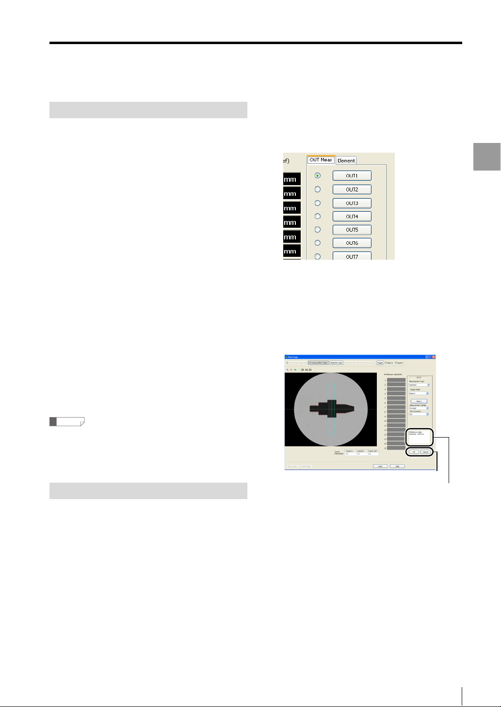
Re-measure (Ref.Value) screen
When [Re-measure (Ref.Value)] is clicked, reference values are displayed on the right side of the image display screen
(or image storage screen).
(1)
(1) [Re-measure (Ref.Value)]
This displays the measurement values in OUT1 to OUT16 according to the setting contents for (2).
The measurement results from the controller are displayed in green or red. Re-measure (Ref.Value) values are
displayed in white.
For details of Re-measure (Ref.Value), see page 4-11.
(2) "OUT meas" / "Element"
This sets "OUT meas" / "Element" for Re-measure (Ref. Value).
For setting procedures, see "How to Set Re-measure (Ref.Value)" (page 4-11).
(3) Load from setting
This loads the setting contents currently registered with TM-Navigator.
(4) Reflect to setting
This displays the setting contents in the setting for TM-Navigator.
To send the new settings to the controller, establish the communication status between TM-Navigator and the
controller, and click "Send settings to controller" (page 2-2).
(2)
(3)
(4)
4-10
- Setup software TM-H1 TM-Navigator User’s Manual -
Page 33
View Image
Help:Ref.Value
The Re-measure (Ref.Value) function of TM-Navigator
displays the measurement result (Re-measure
(Ref.Value)) by using the measurement image obtained
from the head and head data to make adjustments. The
head data to be used is saved on the hard disk drive in
the computer and is changed according to the following
conditions.
• When receiving the settings from the controller:
The head data for the connected head is overwritten
and saved.
• When selecting "Head Select":
The initial data in TM-Navigator is overwritten and
saved.
In the following cases, the measurement result by Remeasure may differ from the actual measurement value
by the controller. In these cases, use the Re-measure
value as a reference value.
• When the head that measured the image for Remeasure is different from the head that obtained the
head data saved on the computer
• When the head data is the initial data in TM-Navigator
To match the Re-measure value with the actual value
measured by the controller, receive the settings from the
controller before re-measurement.
Click the [Re-measure (Ref.Value)] button.
4
The display shows that the [Re-measure (Ref.Value)]
button is pressed down, and "OUT meas" and
"Element" are displayed.
Press the "OUT meas" or "Element" tab
5
to select the number to set and make
the settings for each item.
The master registration image is displayed on the
view image area, and the measurement result is
updated and displayed.
Displaying the Measurement Data
Reference
The following contents will not be reflected in the Remeasure value.
• Auto-zero
• Average (Always set to 1.)
How to Set Re-measure (Ref.Value)
This section describes how to set the area for "OUT
meas" and "Element".
For more information on each item, see "TM-3000 Series
User's Manual".
Display the [View Image] window.
1
Click the [Start image capturing] button.
2
Load the image from the controller to display.
Click the [Stop image capturing] button.
3
Image capturing stops.
- Setup software TM-H1 TM-Navigator User’s Manual -
OK / Cancel
Reference value
The Re-measure result using the master image is displayed
as a reference value according to the setting contents.
Clicking [OK] button enables the setting contents
and the Re-measure (Ref.Value) is displayed. If this
is not needed, cancel it.
Click the [Reflect to setting] button on
6
the [View Image] window.
The contents set for "OUT meas" or "Element" are
reflected in TM Navigator software and not in the
controller.
To reflect the settings in the controller,
7
click the [Send settings to controller]
button on the main window.
4-11
Page 34

View Image
Inspection Areas
Drag angles or sides of each figure to draw areas.
Shapes that can be set beforehand are determined
according to the setting contents. Shapes that can be set
are as follows.
Displaying the Measurement Data
Rectangle /
Rotated rectangle
Circle Line Point
Moving the angle
When the mouse pointer is placed on the angle with
marker, the shape of the pointer changes to . It can
be moved by dragging.
<Display example>
Triangle Circular arc
Moving the whole area
When the mouse pointer is placed within the area, the
shape of the pointer changes to . The whole area
moves can be moved by dragging.
<Display example>
Rotating
When the mouse pointer is placed on the angle with
marker after clicking the [Rotation] button, the shape of
the pointer changes to . The area can be rotated by
dragging.
[Rotation] button:
<Display example>
Moving the side
When the mouse pointer is placed on the side of area, the
shape of the pointer changes to . The shape can be
changed by dragging.
<Display example>
Reference
• When the following modes are selected, the area can
be rotated.
"Line edge" for "Auxil.Meas."
"Arc edge" for "Auxil.Meas."
• Click the [Rotation] button again to move the angle.
4-12
- Setup software TM-H1 TM-Navigator User’s Manual -
Page 35

Data Storage
Data Storage
Data storage is a function for storing measurement data in the internal memory of the controller.
Stored data can be displayed on TM-Navigator with a graph and can be transferred to an Excel file.
Functions and Display
In the [Data storage] window, measurement data that is stored in the controller can be loaded, displayed and
transferred to an Excel file.
The settings for data storage and directions for starting or stopping measurement data acquisition can be changed.
(1) (2) (3) (4) (5)
Displaying the Measurement Data
(6)
(7)
(8)
(9)
(10)
(11)
(12) (13) (14) (15)
(1) [Start storage] button
Starts storing the measurement data from the controller.
(2) [Stop storage] button
Stops storing the measurement data from the controller.
(3) [Clear storage data] button
Clears all of the measurement data from all of the OUT settings that are stored in the internal memory of the
controller.
- Setup software TM-H1 TM-Navigator User’s Manual -
4-13
Page 36

Data Storage
(4) [Excel transfer start] button
Stored data can be transferred to Excel and saved as a file.
For operation method, see "Transferring the storage data to Excel" (page 4-18).
For the contents of the Excel file, see "Excel File" (page A-5).
(5) [Data storage] button
Displays the [Data storage] dialog box.
Displaying the Measurement Data
This dialog box can be used to configure the controller's data storage settings.
No. of data points
Skipping
Received
Send
Sets the number of data points to store.
Setting range: 1 to 65536
Sets the number of data point skipped before being stored as data.
Setting range: 1 / 2 / 5 / 10 / 20 / 50 / 100
Receives all of the storage settings (program No. 00 to 15 and environment settings) from the
controller.
Sends all of the storage settings (program No. 00 to 15 and environment settings) that are
being edited from TM-Navigator to the controller.
Close Closes the [Data storage] dialog box.
(6) Amount of stored data and current status display
Displays the amount of data that is stored on the controller and current operation status of the controller.
(7) Graph display information for each OUT setting
Changes the graph display for each OUT setting.
Switches between showing and hiding the graph.
Check this checkbox to display the graph.
Displays the name of the graph. The name can be changed.
Moves the graph in the horizontal direction.
Displays the color used for the graph line. Any color can be set.
(8) Cursor information display area
Displays the information for cursor A and cursor B on the graph display area.
Cursors A and B can be moved by dragging the mouse.
(9) [Read storage data] button
Reads the data that is stored in the connected controller on TM-Navigator.
4-14
- Setup software TM-H1 TM-Navigator User’s Manual -
Page 37

(10)
Data storage tool bar
Performs operations on the displayed graph of stored data.
Display the graph
separately
Display the graph
overlapping
When there are multiple OUT settings for stored data, the graphs for the OUT
settings are displayed one above another.
When there are multiple OUT settings for stored data, the graphs for the OUT
settings are displayed on top of each other.
Zoom in vertically This button zooms in on the displayed graph in the vertical direction.
Zoom out vertically This button zooms out on the displayed graph in the vertical direction.
Zoom in horizontally This button zooms in on the displayed graph in the horizontal direction.
Zoom out horizontally This button zooms out on the displayed graph in the horizontal direction.
Data Storage
Displaying the Measurement Data
Automatically adjust the
vertical scale
Raise display position
Lower display position
This button automatically changes the vertical width of the graph to fill the
current size of the [Data storage] window.
This button moves the graph upwards when the data extends beyond the view
graph area.
This button moves the graph downwards when the data extends beyond the
view graph area.
Hide the cursor This button hides the cursor.
Select cursor A This button allows cursor A to be operated in the view graph area.
Select cursor B This button allows cursor B to be operated in the view graph area.
(11)
View graph area
Select cursor A and
cursor B
Reverse the
background and grid
display colors
This button allows cursor A and cursor B to be manipulated in the view graph
area simultaneously.
Change the back ground of the view graph area. (The color is reversed in
black/white.)
Displays the graph of data that is stored in the controller.
The graphs are displayed in different colors for each OUT setting.
(12)
[Read from file] button
Reads and displays data that is stored on the computer (*.dst).
(13)
[Save to file] button
Reads stored data from the controller and saves it as a file in the data storage format (*.dst).
(14)
[Close] button
Closes the [Data storage] window.
(15)
[Help] button
Opens the help menu for TM-Navigator.
- Setup software TM-H1 TM-Navigator User’s Manual -
4-15
Page 38

Data Storage
Displaying the [Data storage] window
Connect TM-Navigator and the
1
controller, check that communication
can be established, and then measure
Displaying the Measurement Data
the target.
"Connecting via USB" (page 1-7)
"Connecting via Ethernet" (page 1-9)
Click the [Data storage] icon on the tool
2
bar.
The [Data storage] window appears.
Alternative
•
Select [Data storage] from the [View] menu.
• Press the "F7" key.
Changing the data storage settings
Select the [Common] tab in the main
1
window and click the [Storage] button.
Select [Data storage] from the
2
[Storage] pull-down menu.
Click the [Data storage] icon on the tool
3
bar.
The [Data storage] window appears.
Click the [Data storage] button.
4
The [Data storage] dialog appears.
Set the values for [No of data points] and [Skipping].
Click the Send Setting to Controller
5
button.
The setting data (program file and environment
setting file) currently set on TM-Navigator is sent to
the controller.
Reference
The data storage settings can also be changed with the
controller.
"TM-3000 Series User's Manual"
4-16
- Setup software TM-H1 TM-Navigator User’s Manual -
Page 39
Data Storage
Starting data storage
Connect TM-Navigator and the
1
controller, check that communication
can be established, and then measure
the target.
"Connecting via USB" (page 1-7)
"Connecting via Ethernet" (page 1-9)
Set the storage settings to "Data
2
storage" in the common settings for
the controller.
"TM-3000 Series User's Manual"
Click the [Data storage] icon on the tool
3
bar.
The [Data storage] window appears.
Click the [Start storage] button.
4
The controller starts storing the measurement
values.
When the amount of stored data matches the value
set for [No of data points] in the [Data storage]
dialog box, the storage stops automatically.
Reference
• The storage interval depends on the trigger settings
and data output timing settings. Data can be stored in
succession or at a specified timing. To stop the data
storage halfway, click the [Stop storage] button.
When you click the [Start storage] button again after the
storage is stopped once, the storage is resumed from
the point where the storage was stopped.
• If communication is not possible between TM-Navigator
and the controller, or if a head is not connected, the
following dialog appears shortly after clicking the [Start
storage] button or the [Read storage data] button.
Check the connection between each head and
between TM-Navigator and the controller. Check that
the controller is set to [Data storage].
Loading the storage data
Displays the data stored in the controller on TMNavigator.
Connect TM-Navigator and the
1
controller, check that communication
can be established, and then measure
the target.
"Connecting via USB" (page 1-7)
"Connecting via Ethernet" (page 1-9)
Start or stop data storage according to
2
"Starting data storage" (page 4-17).
Click the [Read storage data] button.
3
The storage data is displayed on TM-Navigator.
Displaying the Measurement Data
- Setup software TM-H1 TM-Navigator User’s Manual -
4-17
Page 40

Data Storage
Transferring the storage data to Excel
The storage data loaded to TM-Navigator from the
controller can be loaded to an Excel file.
Reference
"Re-measure (Ref.Value)" data cannot be loaded.
Displaying the Measurement Data
Connect TM-Navigator and the
1
controller, check that communication
can be established, and then measure
the target.
"Connecting via USB" (page 1-7)
"Connecting via Ethernet" (page 1-9)
Click the [Start storage] button.
2
3
4
"Starting data storage" (page 4-17)
Click the [Read storage data] button.
The storage data is loaded into TM-Navigator.
Click the [Excel transfer start] button on
the [Data storage] window.
The [Excel setting] window appears.
(3) Start writing cell
Specify which cell to begin transferring data to.
(4) [All ON] button
Check marks are added to all of the items.
(5) [All OFF] button
Check marks are removed from all of the items.
(6) [Transfer] button
When the button is clicked, Excel starts up and
the measurement values are entered in the
specified cells.
(7) [Cancel] button
This cancels the set contents and closes the
[Excel setting] window.
Click the [Transfer] button.
5
Excel starts up and is displayed. Then, the data is
transferred to the specified sheet.
(1)
(2)
(6)
(1) Forward sheet name
Enter the Excel sheet name to which the data is
to be transferred.
(2) Transfer list
Check the items to be transferred.
Items (date or OUT number) and the cell number
of the first row to be transferred are displayed.
4-18
(7)
- Setup software TM-H1 TM-Navigator User’s Manual -
(3)
(4)
(5)
Page 41
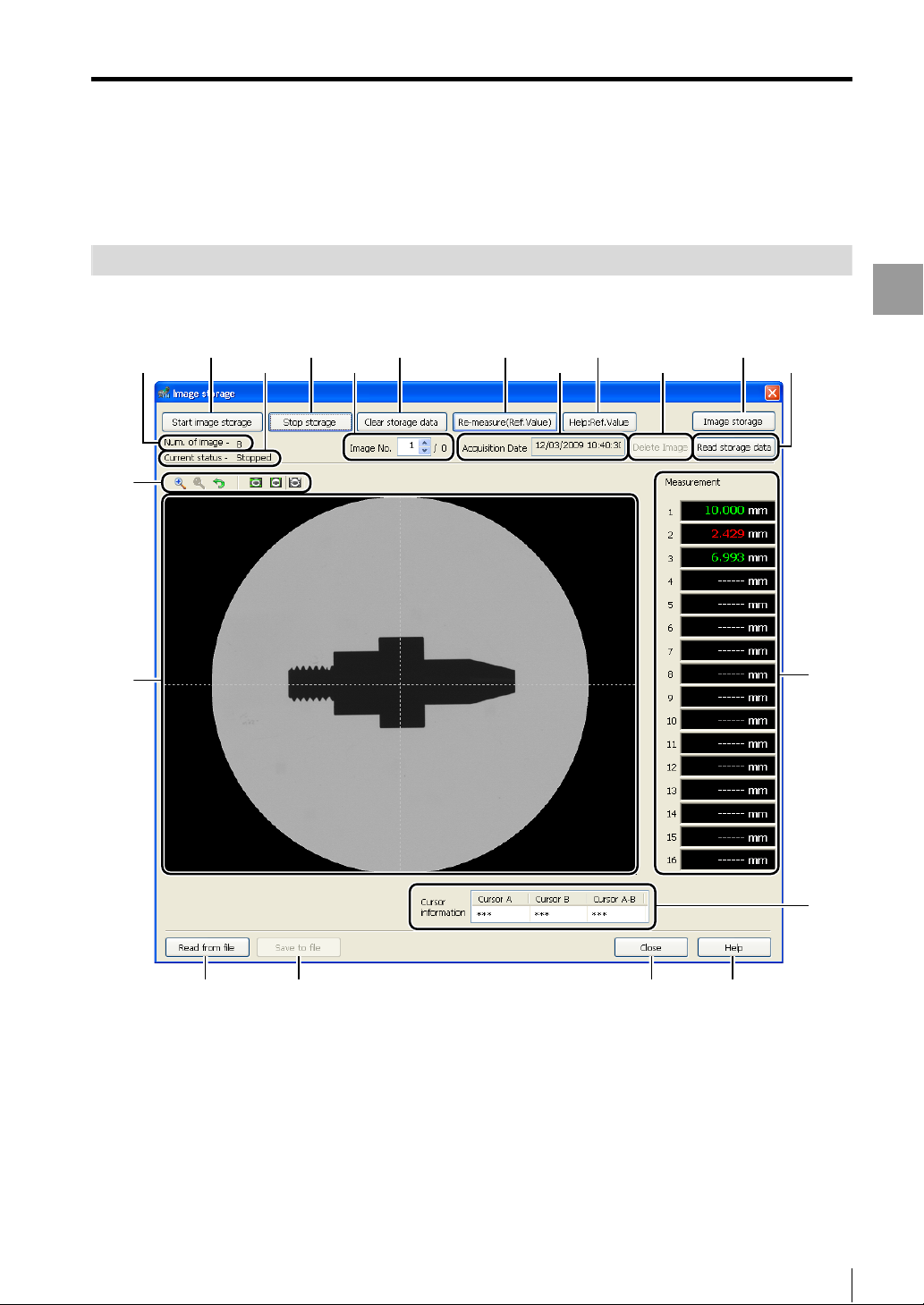
Image Storage
Image Storage
Image storage is a function for storing the image during measurement in the internal memory of the controller.
Using the TM-Navigator allows the stored data to be checked.
Functions and Display
In the [Image storage] window, image data that is stored in the controller can be loaded, displayed and saved as a file.
The settings for image storage and directions for starting or stopping image data acquisition can be changed.
(13)
(7)
(2) (3) (5) (6)
(8) (9) (10) (11) (12)
(4)(1)
Displaying the Measurement Data
(14)
(15)
(16)
(17) (18) (19) (20)
- Setup software TM-H1 TM-Navigator User’s Manual -
4-19
Page 42

Image Storage
(1) [Start image storage] button
Starts storing the image data from the controller.
(2) [Stop storage] button
Stops storing the image data from the controller.
(3) [Clear storage data] button
Displaying the Measurement Data
Clears all of the image data that is stored in the internal memory of the controller.
(4) [Re-measure (Ref.Value)] button
This function changes or confirms the measurement settings using saved images.
The confirmed setting conditions can be saved and sent to the controller.
"Functions and Usage of Re-measure (Ref.Value)" (page 4-10)
(5) [Help:Ref.Value] button
The help file for Re-measure (Ref.Value) is displayed.
(6) [Image storage] button
Displays the [Image storage] dialog box.
This dialog box can be used to configure the controller's image storage settings.
"Changing the image storage settings" (page 4-22)
(7) Num. of image
Displays the number of images that are stored on the controller.
(8) Current status
Displays the storage status (Storing / Stopped)
(9) Image No.
Displays the number of images and selects the image No. that is displayed on the view image area.
(10)
Acquisition Date
Displays the date and time when the image selected for (9) Image No. was stored on the controller.
(11)
[Delete Image] button
Deletes the displayed image data.
(12)
[Read storage data] button
Reads the image data in the connected controller on TM-Navigator.
4-20
- Setup software TM-H1 TM-Navigator User’s Manual -
Page 43

(13)
Image storage tool bar
Zoom in This button zooms in the displayed image.
Zoom out This button zooms out the displayed image.
Image Storage
Default display This button returns the displayed image to the default display size.
Horizontal cursor This button displays the horizontal cursors on the view image area.
Vertical cursor This button displays the vertical cursors on the view image area.
Hide the cursor This button hides the cursors.
(14)
View image area
Displays the loaded storage data.
(15)
View measurement value area
This displays the measurement values in OUT numbers 1 to 16.
According to the evaluation results, green (GO evaluation), red (HI/LO evaluation) or white (evaluation standby) is
displayed.
(16)
Cursor information
This displays the position information of the cursor displayed in the view image area.
(17)
[Read from file] button
When opening the image storage file (*.bst) saved on the computer, the corresponding image file is read and
displayed.
If reading fails, the following window appears.
Displaying the Measurement Data
(18)
[Save to file] button
Sets the image for saving.
Reads stored data from the controller and saves it as a file in the Bitmap format (*.bmp).
The image storage file (*.bst) is saved also.
(19)
[Close] button
This closes the [Image storage] window.
(20)
[Help] button
Opens the help menu for TM-Navigator.
- Setup software TM-H1 TM-Navigator User’s Manual -
4-21
Page 44
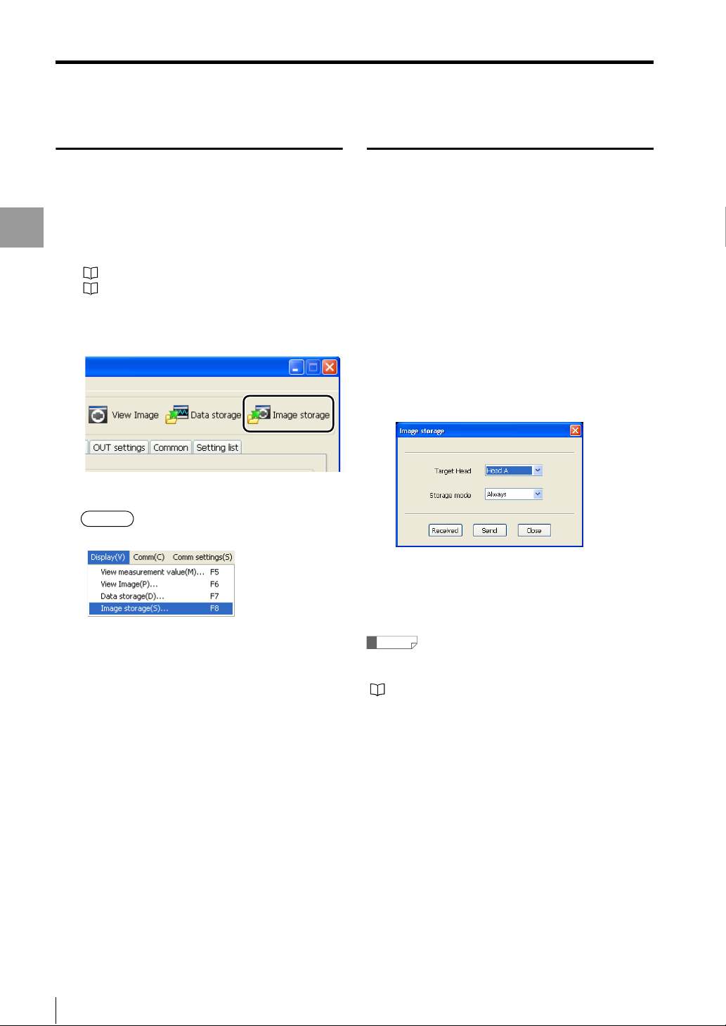
Image Storage
Displaying the [Image storage] window
Connect TM-Navigator and the
1
controller, check that communication
can be established, and then measure
Displaying the Measurement Data
the target.
"Connecting via USB" (page 1-7)
"Connecting via Ethernet" (page 1-9)
Click the [Image storage] icon on the
2
tool bar.
The [Image storage] window appears.
Alternative
• Select [Image storage] from the [Display] menu.
Changing the image storage settings
Select the [Common] tab in the main
1
window and click the [Storage] button.
Select [Image storage] from the
2
[Storage] pull-down menu.
Click the [Image storage] icon on the
3
tool bar.
The [Image storage] window appears.
Click the [Image storage] button.
4
The [Image storage] dialog appears.
Set the "Target Head" and "Storage item".
• Press the "F8" key.
Click the [Send] button on the [Image
5
storage dialog.
All of the setting data is sent to the controller.
Reference
The image storage settings can also be changed with the
controller.
"TM-3000 Series User's Manual"
4-22
- Setup software TM-H1 TM-Navigator User’s Manual -
Page 45
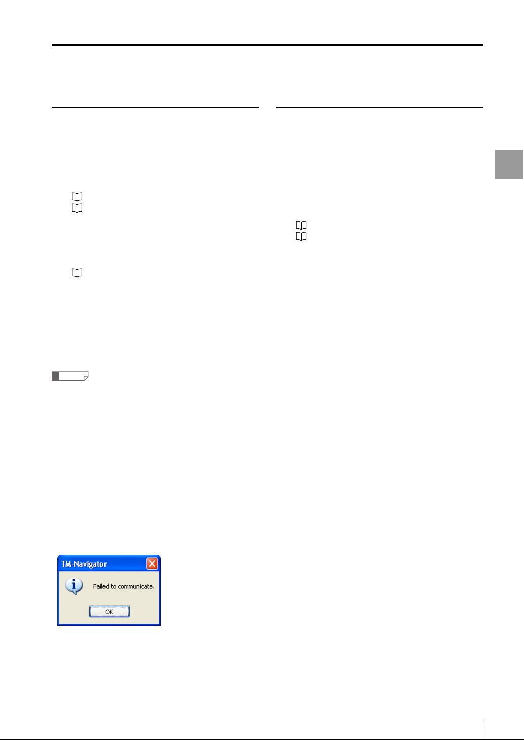
Image Storage
Starting image storage
Connect TM-Navigator and the
1
controller, check that communication
can be established, and then measure
the target.
"Connecting via USB" (page 1-7)
"Connecting via Ethernet" (page 1-9)
Set the storage settings to "Image
2
storage" in the common settings for
the controller.
"TM-3000 Series User's Manual"
Click the [Image storage] icon on the
3
tool bar.
The [Image storage] window appears.
Click the [Start image storage] button.
4
The controller starts storing the measurement values.
Reference
• The storage interval is determined based on the
storage settings. Data can be stored in succession or at
a specified timing. To stop the data storage before the
buffer is full, click the [Stop storage] button.
When you click the [Start image storage] button again
after the storage is stopped once, the storage is
resumed from the point where the storage was stopped.
• If communication is not possible between TM-Navigator
and the controller, or if a head is not connected, the
following dialog appears shortly after clicking the [Start
image storage] button or the [Read storage data]
button.
Check the connection between each head and
between TM-Navigator and the controller. Check that
the controller is set to [Image storage].
Loading the storage data
Displays the data stored in the controller on TMNavigator.
Connect TM-Navigator and the
1
controller, check that communication
can be established, and then measure
the target.
"Connecting via USB" (page 1-7)
"Connecting via Ethernet" (page 1-9)
Start or stop data storage according to
2
"Starting image storage" (page 4-23).
Click the [Read storage data] button.
3
The storage data is displayed on TM-Navigator.
Displaying the Measurement Data
- Setup software TM-H1 TM-Navigator User’s Manual -
4-23
Page 46
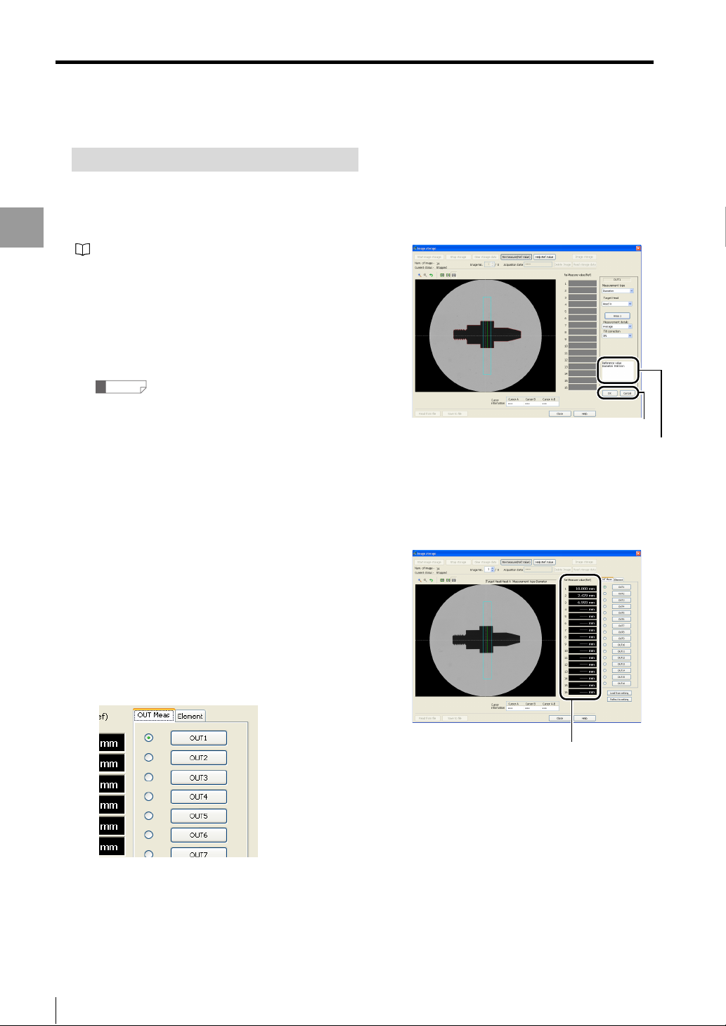
Image Storage
How to Set Re-measure (Ref.Value)
This section describes how to set the area for "OUT meas"
and "Element".
For more information on each item, see "TM-3000 Series
User's Manual".
Displaying the Measurement Data
"Help:Ref.Value" (page 4-11)
Display the [Image storage] window.
1
Click the [Start image storage] button.
2
Stores images into the internal memory of the
controller.
Reference
If images have already been stored, skip steps 2
and 3.
Click the [Stop storage] button.
3
This stops storing the image data.
Click the [Read storage data] button.
4
Stored image data is loaded into TM-Navigator and
displayed.
Press the "OUT meas" or "Element" tab
7
to select the available settings for each
item.
The master registration image is displayed on the view
image area.
OK / Cancel
Reference value
The Re-measure result using the master image is
displayed as a reference value according to the
settings. Clicking [OK] button enables the settings
and the Re-measure (Ref.Value) to be displayed. If
this is not needed, cancel it.
Select the image to re-measure with
5
[Image No.].
Click the [Re-measure (Ref.Value)]
6
button.
The display shows that the [Re-measure (Ref.Value)]
button is pressed down, and "OUT meas" and
"Element" are displayed.
[Re-measure (Ref.Value)]
Click the [Reflect to setting] button on
8
the "Image storage" window.
The contents set for "OUT meas" or "Element" are
reflected in the TM Navigator software.
To send the settings to the controller,
9
click the [Send settings to controller]
button on the main window.
4-24
- Setup software TM-H1 TM-Navigator User’s Manual -
Page 47

Chapter
5
Setting Each Function
This chapter describes setting each function for TM-Navigator.
Setting Items. . . . . . . . . . . . . . . . . . . . . . . . . . . . . . . . . . . . . .5-2
Environment Settings . . . . . . . . . . . . . . . . . . . . . . . . . . . . .5-21
Setting Each Function
- Setup software TM-H1 TM-Navigator User’s Manual -
5-1
Page 48
Setting Items
Setting Items
This section describes the settings that can be configured in TM-Navigator.
Select the tabs to switch between the settings.
Reference
• Each setting can be configured for each program No.
• Send the settings to the controller after configuration is complete.
Setting Each Function
Ta b
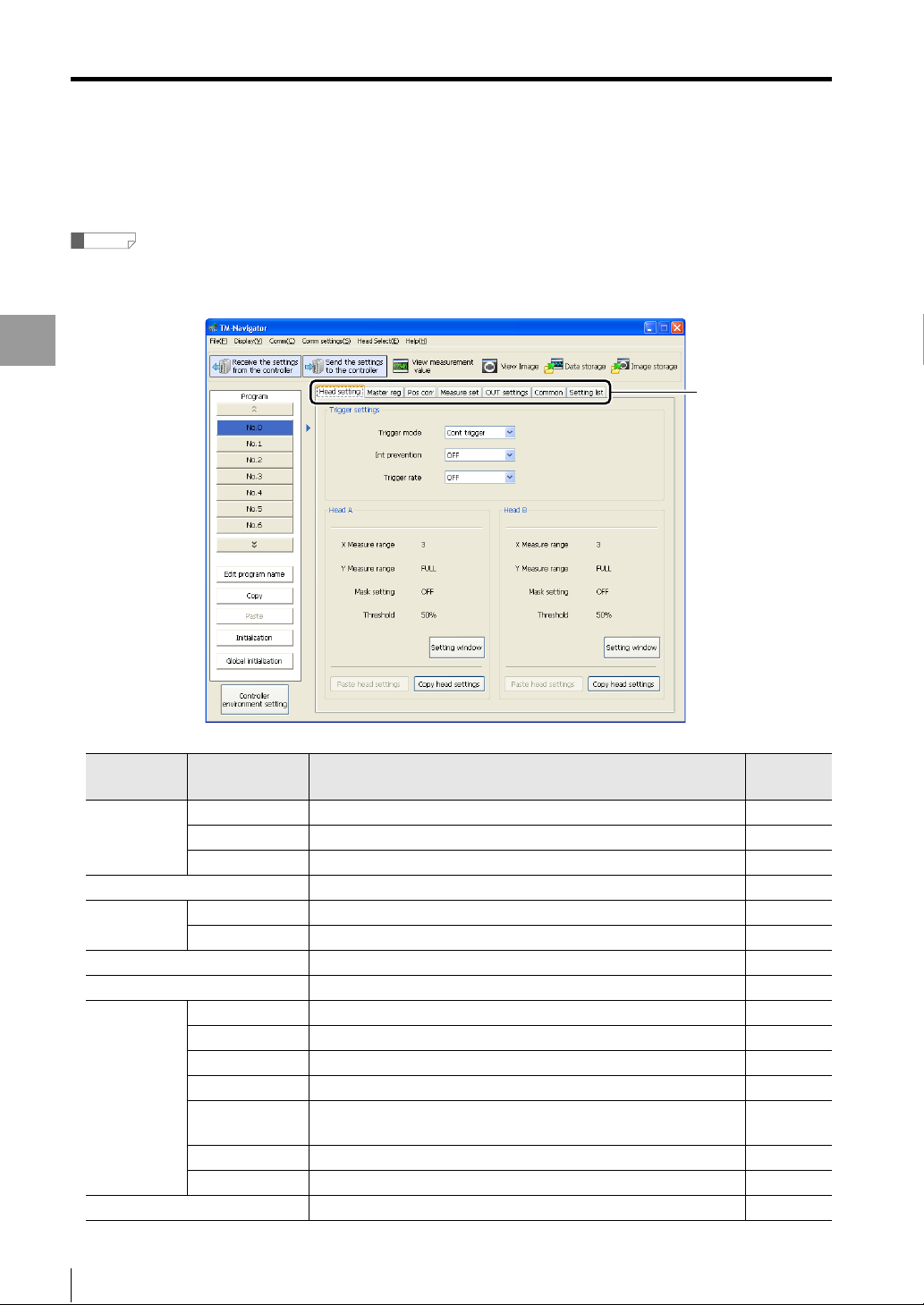
Tab Setting items Description
Head setting Trigger settings
Head A Sets the measurement conditions for Head A. 5-4
Head B Sets the measurement conditions for Head B. 5-4
Master reg
Pos corr Head A Sets the position correction for the displayed image for Head A. 5-9
Head B Sets the position correction for the displayed image for Head B. 5-9
Measure set Set the inspection and element tools. 5-10
OUT settings Sets the OUT conditions for OUT1 to OUT16. 5-11
Common TIMING terminal Sets TIMING1 /TIMING2 for each OUT setting. 5-16
ZERO terminal Sets ZERO1 /ZERO2 for each OUT setting. 5-16
Binary output Sets binary output for each OUT setting. 5-17
Analog output
Storage When storing data in the controller, select either data storage or
Auto-send Sets auto-send for each OUT setting. 5-19
Data out timing Sets the output timing for data. 5-19
Setting list Displays the list of the settings. 5-20
5-2
Configures the trigger settings that are common for Head A and Head B.
Loads standard images for measurement setting and position correction.
Sets the analog output conditions separately for CH1 and CH2.
image storage.
- Setup software TM-H1 TM-Navigator User’s Manual -
Reference
page
5-3
5-6
5-17
5-18
Page 49

Head Settings
Sets the measurement conditions for Head A and Head B.
For more information about the head settings, see "TM-3000 Series User's Manual".
Setting Items
Setting Each Function
(1)
(2)
(3)
(4)
(7)
(5) (6) (7) (5) (6)
Trigger settings
Setting items Setting range Default value
(1) Trigger mode Cont trigger / External trigger Cont trigger
(2) Int prevention ON / OFF OFF
(3) Trigger rate ON / OFF OFF
Head A / Head B
Setting items Description
(4) View head setting area Displays the setting overview for the head settings.
(5) Paste head settings Pastes the copied head settings into the currently displayed program number.
(6) Copy head settings Copies the currently selected head settings.
The copied head settings can be pasted with [Paste head settings].
(7) Setting window
Displays the [Head setting] window and performs advanced settings for the head.
The settings are displayed in (4) [View head setting area].
- Setup software TM-H1 TM-Navigator User’s Manual -
5-3
Page 50
Setting Items
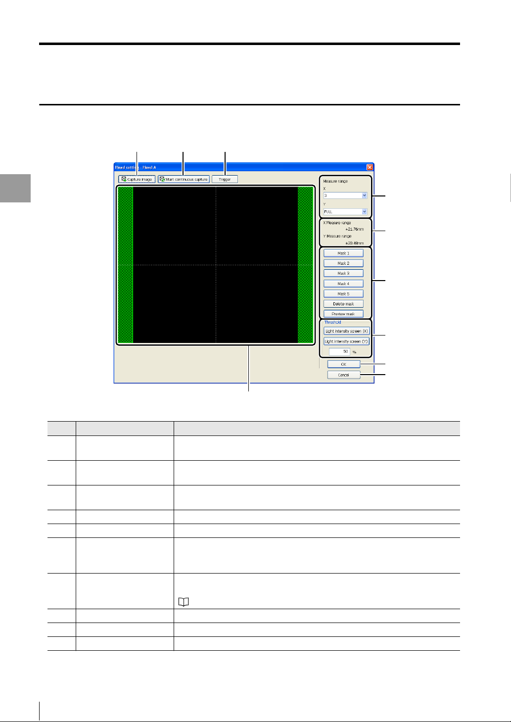
Setting window (Head A / Head B)
Setting Each Function
(1)
(2) (3)
(4)
(5)
(6)
(7)
(8)
(9)
(10)
Setting items Description
(1) Capture image This captures the latest image from the controller only once and displays the
image on the view image area.
(2) Start continuous capture This captures the latest image from the controller in succession and displays the
images on the view image area.
(3) Trigger When the trigger mode is "External trigger", a trigger is input by clicking the
[Trigger] button.
(4) Measure range (X / Y) This sets the measurement range for X direction and Y direction.
(5) Measure range display This displays the range actually measured based on the setting in (4).
(6) Mask setting / Preview This sets the mask areas (Mask1 to Mask5) or deletes them.
Clicking [Preview mask] button displays the image and the mask area on the
view image area.
(7) Threshold setting The sets the threshold to judge as bright or dark.
Clicking Light intensity screen (X) or (Y) displays each screen and cursor.
"Light intensity (X)/Light intensity (Y) screen" (page 5-5)
(8) OK This confirms the set contents and closes the window.
(9) Cancel This cancels the set contents and closes the window.
(10) View image area This displays images and mask areas.
5-4
- Setup software TM-H1 TM-Navigator User’s Manual -
Page 51

Setting Items
Light intensity (X)/Light intensity (Y) screen
On this screen, the threshold can be set while confirming the the amount of light at the position specified by the cursor.
< Light intensity (X)>
(1)
(3)
(2)
Setting Each Function
< Light intensity (Y)>
(1)(2)
(3)
Setting items Description
(1) Position cursor Place the mouse cursor on the position cursor and move to the position for
confirming the light intensity.
(2) Threshold cursor Move the threshold cursor while confirming the light intensity.
Moving the threshold cursor changes (3) [Threshold] value.
(3) Threshold The sets the value to judge as bright or dark.
Changing the threshold also moves the (2) Threshold cursor.
- Setup software TM-H1 TM-Navigator User’s Manual -
5-5
Page 52

Setting Items
Master registration
For more information about the master registration, see "TM-3000 Series User's Manual".
Setting Each Function
(1)
Setting items Description
(1) View master image area This displays the registered master image.
(2) Register the master image The master image registration window appears.
"Master image registration window" (page 5-7)
* Without registration, images are not displayed.
(2)
*
5-6
- Setup software TM-H1 TM-Navigator User’s Manual -
Page 53
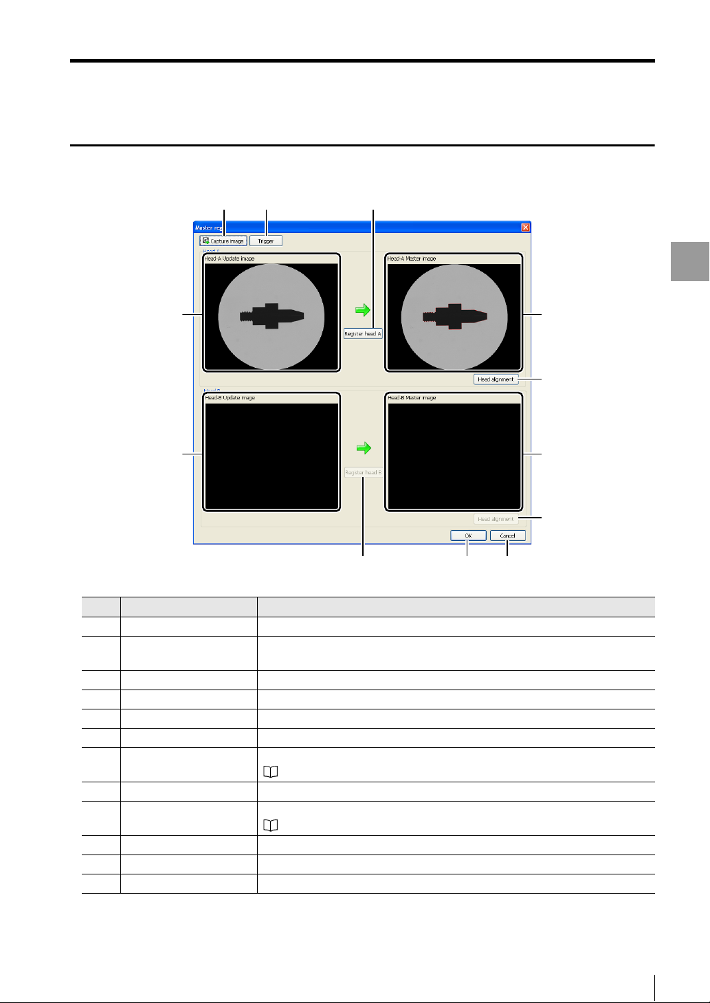
Master image registration window
Setting Items
(4)
(5)
(1)
(2) (3)
(10)
Setting Each Function
(6)
(7)
(8)
(9)
(11) (12)
Setting items Description
(1) Capture image This captures images of Head A and Head B from the controller.
(2) Trigger When the "External trigger" is set for "Trigger settings" in "Head setting", a trigger
is input by clicking the [Trigger] button.
(3) Register head A This registers (4) "Head-A Update image" as a master image.
(4) Head-A Update image This displays the image of Head A captured from the controller.
(5) Head-B Update image This displays the image of Head B captured from the controller.
(6) Head-A Master image This displays the set master image of Head A.
(7) Head Alignment This displays the head alignment window for Head A.
"Head alignment window" (page 5-8)
(8) Head-B Master image This displays the set master image of Head B.
(9) Head Alignment This displays the head alignment window for Head B.
"Head alignment window" (page 5-8)
(10) Register head B This registers (5) "Head-B Update image" as a master image.
(11) OK This confirms the set contents and closes the window.
(12) Cancel This cancels the set contents and closes the window.
- Setup software TM-H1 TM-Navigator User’s Manual -
5-7
Page 54

Setting Items
Head alignment window
For more information about the head alignment, see "TM-3000 Series User's Manual".
(1)
Setting Each Function
(8)
Setting items Description
(1) Zoom in/Zoom out/Return This button zooms in/out the image in the view image area or returns to the
original view.
(2) Correction This selects whether to correct (ON) or not (OFF).
(3) Correction direction This sets the edge in the area set for Range 1/Range 2 to Horizontal/Vertical.
(4) Range 1/Range 2/Add/
Delete
(5) Correction angle display/
Preview correction
(6) OK This confirms the set contents and closes the window.
(7) Cancel This cancels the set contents and closes the window.
(8) View image area This displays the image.
* If the correction range exceeds ±20 degrees, [Preview correction] button is not displayed.
This sets the edge range for correction.
To add or delete Range 2, click the [Add]/[Delete] button.
This displays the correction angle according to the set range.
Clicking the [Preview correction] button displays the image after correction.
(2)
(3)
(4)
(5)
(6)
(7)
*
5-8
- Setup software TM-H1 TM-Navigator User’s Manual -
Page 55
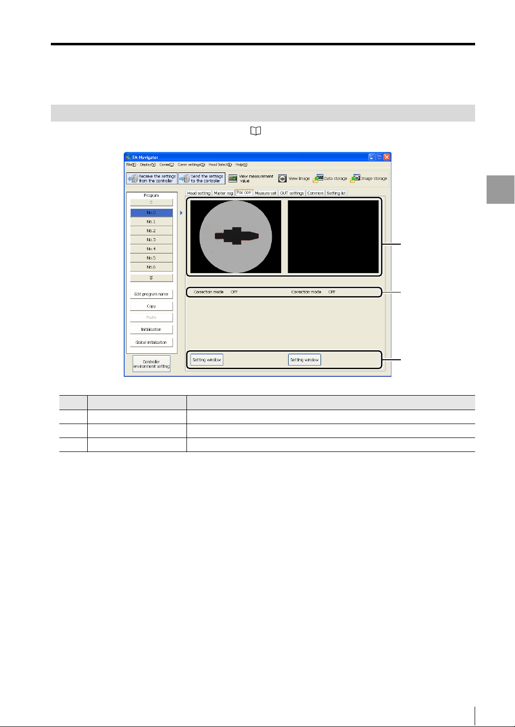
Position Correction
For more information about the position correction, see "TM-3000 Series User's Manual".
Setting Items
Setting Each Function
(1)
(2)
Setting items Description
(1) View master image area*The master image is displayed.
(2) Correction mode The currently set correction mode is displayed.
(3) Setting Window The position correction window appears.
* This is not displayed when the master image has not been registered.
(3)
- Setup software TM-H1 TM-Navigator User’s Manual -
5-9
Page 56

Setting Items
Measurement Settings
For more information about the measurement settings, see "TM-3000 Series User's Manual".
Setting Each Function
(1)
Setting items Description
(1) Setting list display This displays the currently set modes.
(2) Setting Window The setting window appears.
(2)
5-10
- Setup software TM-H1 TM-Navigator User’s Manual -
Page 57
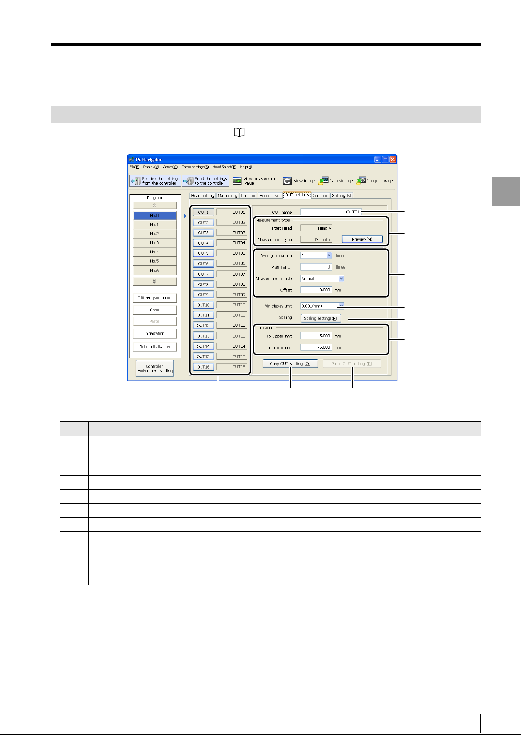
OUT Settings
For more information about the OUT settings, see "TM-3000 Series User's Manual".
Setting Items
(1)
(2)
(3)
(4)
(5)
(6)
(7)
(8) (9)
Setting items Description
(1) OUT name This changes the name of the selected OUT setting.
(2) Measurement type This displays the measurement type. Clicking the [Preview] button displays the
setting area.
(3) Measurement conditions This sets the measurement conditions.
(4) Minimum display unit This selects the minimum display unit for the measurement value.
(5) Scaling settings The [Scaling settings] dialog box appears and sets the scaling.
(6) Tolerance settings This sets the upper and lower limits for tolerance.
(7) OUT setting No. This selects the OUT setting No. that you want to configure.
(8) Copy OUT settings This copies the currently selected OUT settings.
The copied OUT settings can be pasted with [Paste OUT settings].
(9) Paste OUT settings This pastes the copied OUT settings into the currently displayed OUT settings.
Setting Each Function
- Setup software TM-H1 TM-Navigator User’s Manual -
5-11
Page 58

Setting Items
Measurement type
The target head and measurement type (mode) set for the measurement settings are displayed.
Clicking [Preview] button displays the master image and measurement area.
Measurement conditions
The measurement conditions can be set in the following range.
Setting Each Function
Setting items Setting range Default value
Average measure 1 / 2 / 4 / 8 / 16 / 32 / 64 / 128 / 256 / 512 / 1024 / 2048 / 4096 1
Alarm error 0 to 255 0
Measurement
mode
Offset 0.000 to 999.999 0.000
Normal / Peak hold 1 /Bottom hold 1 /
P-to-p hold 1 / Average hold 1 /
Peak hold 2 / Average hold 2 /P-to-p hold 2 /
Average hold 2 / Sample hold
Normal
Minimum display unit
The minimum display unit can be set in the following range.
The display ranges for offset, scaling setting and tolerance setting will also be changed in addition to the display range
for the measured value.
Setting items Setting range Default value
Min display unit*1 mm / 0.1 mm / 0.01 mm / 0.001 mm / 1 Pm / 0.1 Pm / 0.01 Pm
* The setting range varies depending on the measurement mode.
For details, see "TM-3000 Series User's Manual".
2
/ 0.1 mm2 / 0.01 mm2 / 0.001 mm2 / 0.0001 mm
1 mm
1 deg / 0.1 deg / 0.01 deg
2
0.001 mm
5-12
- Setup software TM-H1 TM-Navigator User’s Manual -
Page 59

Scaling
The displayed value for the measurement value can be scaled (calibrated) as desired.
Scaling setting screen
When the [Scaling settings] button is clicked, the following setting screen appears.
1
Setting Items
Setting Each Function
Click the [Acquire measure] button.
2
The setting values on TM-Navigator are sent to the controller and the measurement value is acquired.
(1)
(2)
(4) (5) (6) (7) (8)
Setting items Description
(1) Acquire measure
(2) Measurement value This displays the acquired measurement value.
(3) Trigger input The trigger is input as an external trigger.
(4) MeasureoInput 1 /
MeasureoInput 2
(5)
Input value 1 / Input value 2
(6) OK This confirms the set contents and closes the window.
(7)
Display value 1 / Display value 2
(8) Cancel This cancels the set contents and closes the window.
This acquires the measurement value from the controller. The value is updated
each time this button is clicked.
This sets the acquired measurement value as Input value 1 or Input value 2.
This sets the input value.
This sets the display value corresponding to the input value.
(3)
- Setup software TM-H1 TM-Navigator User’s Manual -
5-13
Page 60
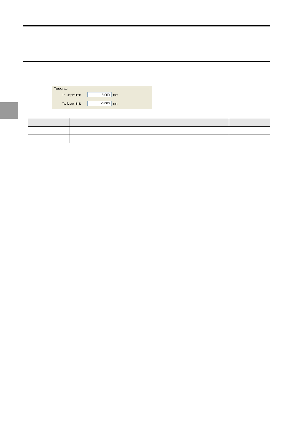
Setting Items
Tolerance settings
The tolerance settings can be set in the following range.
Setting Each Function
Setting items Setting range Default value
Tol upper limit -999.999 to 999.999 5.000
Tol lower limit -999.999 to 999.999 -5.000
5-14
- Setup software TM-H1 TM-Navigator User’s Manual -
Page 61

Common Settings
For more information about the common settings, see "TM-3000 Series User's Manual".
Setting Items
Setting Each Function
(1) (2)
Setting items Description
(1) Common setting items This selects the items to configure in common settings.
(2) Setting contents This configures the settings selected in (1).
- Setup software TM-H1 TM-Navigator User’s Manual -
5-15
Page 62

Setting Items
TIMING terminal
This setting configures the TIMING terminal.
For details, see "TM-3000 Series User's Manual".
Setting Each Function
Setting items Description
TIMING settings This configures the TIMING settings for each OUT setting.
All TIMING1 This sets all of the OUT settings to TIMING1.
All TIMING2 This sets all of the OUT settings to TIMING2.
ZERO terminal
This setting configures the ZERO terminal.
For details, see "TM-3000 Series User's Manual".
Setting items Setting range
ZERO settings This configures the ZERO settings for each OUT setting.
All ZERO1 This sets all of the OUT settings to ZERO1.
All ZERO2 This sets all of the OUT settings to ZERO2.
5-16
- Setup software TM-H1 TM-Navigator User’s Manual -
Page 63

Binary output
This setting configures the binary output.
For details, see "TM-3000 Series User's Manual".
Setting Items
Setting Each Function
Setting items Description
Binary output settings This configures the binary output settings for each OUT setting.
Check the [Judgment] checkbox to use the tolerance comparators instead of the
binary output.
All ON This checks all of the checkboxes.
All OFF This unchecks all of the checkboxes.
Analog output
This setting configures the analog output.
For details, see "TM-3000 Series User's Manual".
Setting items Description
CH1 output selection This selects the OUT setting to output with CH1.
CH1 analog scaling This sets the output voltage value for CH1 compared to the measurement value.
CH2 output selection This selects the OUT setting to output with CH2.
CH2 analog scaling This sets the output voltage value for CH2 compared to the measurement value.
- Setup software TM-H1 TM-Navigator User’s Manual -
5-17
Page 64
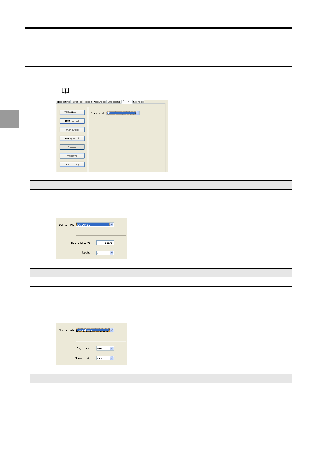
Setting Items
Storage
This setting configures the storage.
For details, see "TM-3000 Series User's Manual".
Setting Each Function
Setting items Setting range Default value
Storage OFF / Data storage / Image storage OFF
Data Storage
Setting items Setting range Default value
No. of data points 1 to 65536 65536
Skipping
* Sampling is performed once for the entire skipping sample size and the data is stored.
Image storage
*
1 / 2 / 5 / 10 / 20 / 50 / 100 1
Setting items Setting range Default value
Target head Head A / Head B / Both heads Head A
Storage conditions
Always / NG only / Manual Always
5-18
- Setup software TM-H1 TM-Navigator User’s Manual -
Page 65

Auto-send
This setting configures Auto-send.
For details, see "TM-3000 Series User's Manual".
Setting Items
Setting Each Function
Setting items Description
Auto-send settings This configures the Auto-send settings for each OUT setting.
All ON This checks all of the checkboxes.
All OFF This unchecks all of the checkboxes.
Data output timing
This setting configures output timing for data.
For details, see "TM-3000 Series User's Manual".
Setting items Setting range Default value
Data out timing Image update / TIMING 1 Image update
- Setup software TM-H1 TM-Navigator User’s Manual -
5-19
Page 66

Setting Items
Setting List
This tab displays a list of the configurations for the settings (head setting, master registration, position correction,
measure set, OUT settings, common settings, environment settings) and the head types.
Setting Each Function
(1)
(2)
Setting items Description
(1) Setting list This tab displays a list of the configurations for the settings (head setting, master
registration, position correction, measure set, OUT settings, common settings,
environment settings) and the head types.
(2) Copy setting list to
clipboard
This copies the currently displayed setting list to the clipboard.
The setting list is tab deliminated, so it can be pasted into Excel or a text editor.
5-20
- Setup software TM-H1 TM-Navigator User’s Manual -
Page 67
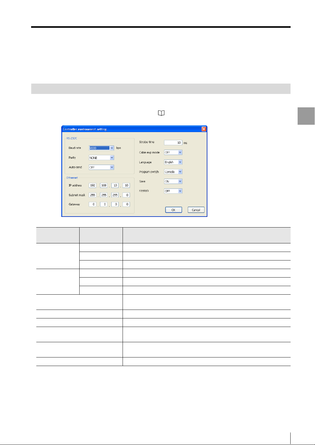
Environment Settings
Environment Settings
These settings set the operating environment of the controller.
The environment settings are saved in a separate file (*.ens) from the program file.
Setting Methods
Click the [Controller environment setting] button in the main window to display the [Controller environment setting]
dialog.
For more information about the environment settings, see "TM-3000 Series User's Manual".
Setting Each Function
Setting items
RS-232C Baud rate This sets the transmission speed.
Ethernet IP address This sets the IP address of the controller.
Strobe time This sets the output refresh time (unit: ms) for the strobe signal when using
Cable exp mode Turn on this setting when using a 30 m head-controller cable (CB-A30).
Language This switches the interface language on the controller.
Program switch This sets whether to switch programs with the console or with an external
Save When this is turned on, the auto zero and program switching settings are
Keylock When this is turned ON, input cannot be accepted from the console.
Detailed
settings
Parity This sets the parity.
Auto-send This sets the auto-send.
Subnet mask This sets the subnet mask.
Gateway This sets the default gateway.
binary output.
input.
saved to the FLASH memory.
Description
- Setup software TM-H1 TM-Navigator User’s Manual -
5-21
Page 68

Environment Settings
Setting Each Function
MEMO
5-22
- Setup software TM-H1 TM-Navigator User’s Manual -
Page 69

Appendix
This chapter describes information such as the troubleshooting
methods and the contents of the error messages.
USB Communication Failure. . . . . . . . . . . . . . . . . . . . . . . . A-2
Excel File. . . . . . . . . . . . . . . . . . . . . . . . . . . . . . . . . . . . . . . . A-5
Error Messages . . . . . . . . . . . . . . . . . . . . . . . . . . . . . . . . . . A-6
Shortcut Key List . . . . . . . . . . . . . . . . . . . . . . . . . . . . . . . . . A-9
Software License Agreement . . . . . . . . . . . . . . . . . . . . . . A-10
Index . . . . . . . . . . . . . . . . . . . . . . . . . . . . . . . . . . . . . . . . . . A-11
Appendix
- Setup software TM-H1 TM-Navigator User’s Manual -
A-1
Page 70

USB Communication Failure
USB Communication Failure
If the "Cannot connect" warning screen appears when the computer cannot correctly recognize the controller.
Perform the following procedure so that the controller can be recognized correctly.
Select "System" from [Control Panel].
1
Double-click on the [System] icon to display the [System Properties] window.
Open "Device Manager".
2
Select the [Hardware] tab at the top of the [System Properties] screen and click the [Device Manager] button to
Appendix
open the device manager.
A-2
- Setup software TM-H1 TM-Navigator User’s Manual -
Page 71

USB Communication Failure
Select the device that is not recognized correctly on the device manager.
3
Look for a device with the "?" or "!" mark next to the name.
If the controller is not recognized correctly, it appears as one of the following:
• "?" or "!" mark next to "KEYENCE TM-3 (USB)"
• An "Unknown device"
If either of these devices is displayed, double-click on the device name. The property window for the selected
device is displayed.
Reference
If there are no device classified as "Unknown device", check for the device under "USB controller".
Appendix
- Setup software TM-H1 TM-Navigator User’s Manual -
A-3
Page 72
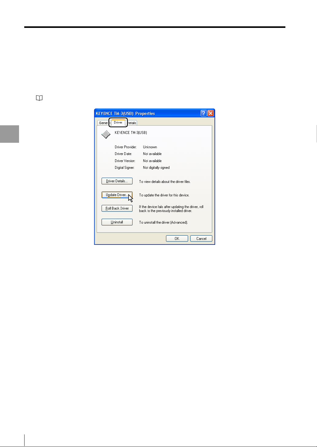
USB Communication Failure
Update the Driver.
4
Select the [Driver] tab and click the [Update Driver] button.
[Search New Hardware Wizard] starts up and begins installing the USB driver.
"Installing the USB Driver" (1-8 page)
Appendix
A-4
- Setup software TM-H1 TM-Navigator User’s Manual -
Page 73

Excel File
This section explains the saved contents when data storage is transferred to Excel.
"Data Storage" (page 4-13)
Excel Transfer Contents of Data Storage
Data storage transferred to Excel is shown as below.
Excel File
Appendix
(1) (2)
(1) Measurement date (month/day/year) and time for points 1 to n for each OUT setting (OUT1 to OUT16)
Reference
The data points that are saved in the file are displayed from top to bottom.
(2) Measurement values 1 to n for each OUT setting (OUT1 to OUT16, starting from the left)
Some measurement values may be displayed on Excel as follows.
Measurement
value
------- -1000000
-FFFFFF -1000000
+FFFFFF +1000000
Reference
The data points that are saved in the file are displayed from top to bottom.
Values on cells
- Setup software TM-H1 TM-Navigator User’s Manual -
A-5
Page 74

Error Messages
Error Messages
This section explains information about the displayed error messages that appear when an error occurs.
Item Display contents Remedy
File operations Failed to read the file ( ).
Verify that the correct file is set.
* The path name is entered in the
parentheses ( ).
Failed to read the environment settings.
( )
The failed item is entered in the parentheses ( ).
*
Appendix
Sending and
receiving
settings
Head setting Image capture failed. Perform "Trigger input" with the controller to
Master
registration
Position
correction
Measurement
setting
Master image is short. Change short master
image for non-reg.
Communication failed. Set the controller to "Measurement screen
Transfer setting failed.
Receive settings failed.
The threshold exceeds the setting range. Set
the value between 10 and 99.
The master image is not registered and
cannot be set. Register the master image in
"Master Image registration".
Correction angle is over the setting range. Set the correction angle to within ±20q.5-8
The correlation value exceeds the setting
range.
The master image is not registered and
cannot be set. Register the master image in
"Master Image registration".
Check whether the selected file is an TMNavigator program file (*.prs) or an
environment setting file (*.ens).
Check the unreadable environment setting
items and set correctly on the controller. 3-3
This occurs when the master image saved
during program saving does not exist in the
same folder as for the selected file.
Put the master image (.bmp) in the same
folder.
(during measurement)".
• Check whether communication is possible
between the controller and computer.
• Set the controller to "Measurement screen
(during measurement)".
• Check whether communication is possible
between the controller and computer.
• Set the controller to "Measurement screen
(during measurement)".
capture the image.
Set the threshold within the displayed range.
Register the master image.
Set the correlation value within the setting
range.
This is displayed when the master image is
not registered when "Search" is selected in
"Measurement type".
Register the "Master image".
Reference
page
3-2
5-6
-
3-4
3-4
5-3
5-3
5-6
5-9
5-10
A-6
- Setup software TM-H1 TM-Navigator User’s Manual -
Page 75

Error Messages
Item Display contents Remedy
OUT settings OUT name length exceeds the setting range.
Enter a name that is no longer than 20
characters long.
The value for the alarm error exceeds the
setting range.
Set the value between 0 and 255.
The value for offset exceeds the setting range.
Set the value between ( ) and ( ).
* The values displayed within the parentheses
( ) vary depending on the units and the
minimum display unit.
The Tol upper limit value exceeds the setting range.
Set the value between ( ) and ( ).
* The values displayed within the parentheses
( ) vary depending on the units and the
minimum display unit.
The Tol lower limit value exceeds the setting range.
Set the value between ( ) and ( ).
* The values displayed within the parentheses
( ) vary depending on the units and the
minimum display unit.
The input value exceeds the setting range.
Set the value between ( ) and ( ).
* The values displayed within the parentheses
( ) vary depending on the units and the
minimum display unit.
The display value exceeds the setting range.
Set the value between ( ) and ( ).
* The values displayed within the parentheses
( ) vary depending on the units and the
minimum display unit.
Common
settings
The measurement value exceeds the setting
range.
Set the value between ( ) and ( ).
* The values displayed within the parentheses
( ) vary depending on the units and the
minimum display unit.
The value for output voltage exceeds the
setting range.
Set the value between -10.500 and 10.500.
Set the span value between -10 and 10.
The same value cannot be set for
measurement.
The amount of storage data exceeds the setting
range.
Set the value between 1 and 65536.
Set the OUT name to 20 or fewer characters.
Set the value for the alarm error between 0
and 255. 5-12
Set the offset within the displayed range.
Set the upper limit within the displayed range.
Set the lower limit within the displayed range.
Set the input value within the displayed range.
Set the display value within the displayed
range.
Set the measurement value within the displayed
range.
Set the value for output voltage between
-10.500 and 10.500. 5-17
Set the value again to meet the input conditions.
Set different values for the input values.
Set the amount of storage data between 1
and 65536. 5-18
Reference
page
5-11
5-12
5-14
5-14
5-13
5-13
5-17
-
5-17
Appendix
- Setup software TM-H1 TM-Navigator User’s Manual -
A-7
Page 76
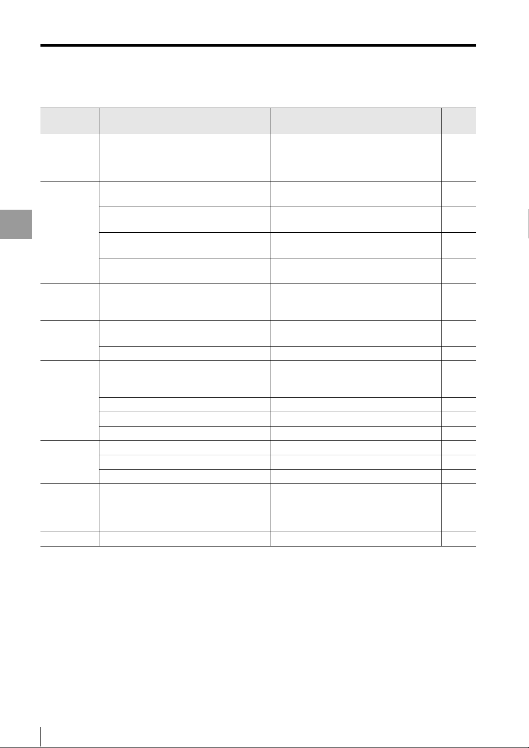
Error Messages
Item Display contents Remedy
Program name
setting
Environment
settings
Appendix
View
measurement
value
View image Image capture failed. Perform "Trigger input" with the controller to
Data storage
Image storage
Communication
process
Help Cannot open HELP file. Install Adobe Reader on the computer. -
The length of the program name exceeds the
setting range.
Enter a name that is no longer than 16
characters long.
The IP address exceeds the setting range.
Set the value between 0 and 255.
The subnet mask exceeds the setting range.
Set the value between 0 and 255.
The gateway exceeds the setting range.
Set the value between 0 and 255.
The strobe time exceeds the setting range.
Set the value between 2 and 100.
Failed to acquire measurement. Set the controller to "Measurement screen
No image is displayed. Capture the image to TM-Navigator. 4-5
The amount of storage data exceeds the setting
range.
Set the value between 1 and 65536.
Change unit settings to data storage. Change unit settings to data storage. -
There is no data to delete.
There is no data to read.
Change unit settings to Image storage. Change unit settings to Image storage. -
There is no data to delete.
There is no data to read.
Failed to communicate.
Set the program name to 16 or fewer
characters.
Set the IP address to groups of numbers
between 0 and 255.
Set the subnet mask to groups of numbers
between 0 and 255.
Set the gateway to groups of numbers
between 0 and 255.
Set the strobe time between 2 and 100.
(during measurement)". -
capture the image.
Set the number of data points for data storage
between 1 and 65536. 4-14
Store measurement data in the controller.
Store measurement data in the controller.
Store image data in the controller.
Store image data in the controller.
• Set the correct communication parameters
for the computer and selected controller.
• Set the controller to "Measurement screen
(during measurement)".
Reference
page
2-3
5-21
5-21
5-21
5-21
4-6
4-13
4-13
4-20
4-20
1-7
-
A-8
- Setup software TM-H1 TM-Navigator User’s Manual -
Page 77

Shortcut Key List
This section provides the TM-Navigator menus and the shortcut keys that can be used.
Menu Submenu Shortcut keys
File(F) Open program file(O) Ctrl+O
Save program file(S) Ctrl+S
Display(V) View measurement value(M)... F5
View Image(P)... F6
Data storage(D)... F7
Image storage(S)... F8
Comm(C) Send the settings to the controller(S) F4
Receive the settings from the controller(R) F3
Help(H) View help(H) F1
Shortcut Key List
Appendix
- Setup software TM-H1 TM-Navigator User’s Manual -
A-9
Page 78

Software License Agreement
Software License Agreement
By using or copying all or any portion of TM-H1 (hereinafter referred to as "This Software"), you accept all the terms and
conditions of this Software License Agreement (hereinafter referred to as "This Agreement").
1. Definition
1.1 "use" or "using" means to access, install, download, copy, or otherwise benefit from using the functionality of This
Software.
1.2 "This Software" means the software and all associated documentation provided by KEYENCE.
2. Grant of License.
2.1 As long as you comply with all of the terms and conditions of This Agreement, KEYENCE grants to you a nonexclusive license to use This Software.
2.2 You may install This Software on a single computer in order to use the products produced by KEYENCE.
Appendix
3. Limitation on Copying.
3.1 You may make one copy of this software for backup purposes only.
4. Restrictions.
4.1 Other than installation of updates or new functions provided by KEYENCE, you may not modify or add any
functions to This Software.
4.2 You may not reverse engineer, decompile, or disassemble This Software.
4.3 You may not create derivative works based on This Software.
4.4 Other than expressly stated by KEYENCE, you may not resell, retransfer, rent, or otherwise redistribute This
Software to any third parties.
5. Copyright.
5.1 This Software is the property of KEYENCE. Other than expressly stated herein, This Agreement does not grant
you any intellectual property rights.
6.Disclaimer.
6.1 This Software is being delivered to you "AS IS" and KEYENCE makes no warranty as to its use or performance. In
no event will KEYENCE or its suppliers be liable to you for any damages, claims, costs, or any lost profits caused
by using This Software.
7. Termination.
7.1 This Agreement will automatically expire when you stop using This Software.
7.2 The license will terminate if you fail to comply with the terms and conditions of This Agreement. KEYENCE may
terminate the license by notifying you that your continued use of This Software is prohibited. In the event the
license is terminated for any reason, you must destroy This Software including its backup copy.
7.3 You will compensate KEYENCE for costs or any lost profits caused by your violation of This Agreement.
8. Governing Law.
8.1 This Agreement will be governed by Japanese laws and regulations.
8.2 If any part of This Agreement is found void and unenforceable, it will not affect the validity of the balance of This
Agreement, which shall remain valid and enforceable according to its terms and conditions.
Trademarks
• Windows 2000/XP/Vista/7 are the registered trademarks of Microsoft Corporation, U.S.A.
• Adobe, the Adobe logo, and Reader are the trademarks or registered trademarks of Adobe System Incorporated in
the United States and other countries.
• Other company or product names mentioned in this manual are trademarks or registered trademarks of their
respective companies. The ™ and ® marks are not used in this manual.
A-10
- Setup software TM-H1 TM-Navigator User’s Manual -
Page 79

Index
Index
B
Before Installation ............................................. 1-2
C
Common settings ............................................ 5-15
Configuring Communication Settings ........ 1-7, 1-9
Connecting ....................................................... 1-9
Connecting via Ethernet ................................... 1-9
Connecting via USB .......................................... 1-7
Connection Method .......................................... 1-7
D
Data Storage ................................................... 4-13
E
Environment Settings ...................................... 5-21
Error Messages .................................................A-6
Excel File ........................................................... A-5
Excel Transfer Contents of Data Storage ..........A-5
Exit .................................................................... 1-6
F
Functions and Display .............4-2, 4-5, 4-13, 4-19
Functions and Usage of Re-measure
(Ref.Value) ...................................................... 4-10
R
Reading and Saving Environment
Setting Files .......................................................3-3
Reading and Saving Program Files ...................3-2
Reading and Saving Setting Files ..................... 3-2
Receiving All Settings ........................................3-4
S
Sending All Settings ..........................................3-4
Sending and Receiving Settings .......................3-4
Setting items ......................................................5-2
Setting List .......................................................5-20
Setting Methods ..............................................5-21
Shortcut Key List ...............................................A-9
Start ...................................................................1-4
Starting and Exiting TM-Navigator ....................1-4
System Environment ..........................................1-2
T
Terms of License Agreement on Use of the
Software ...........................................................A-10
U
Uninstalling TM-Navigator .................................1-3
USB Communication Failure .............................A-2
Appendix
H
Head setting ..................................................... 5-3
Help:Ref.Value ................................................ 4-11
How to Set Re-measure (Ref.Value) ...... 4-11, 4-24
I
Image storage ................................................. 4-19
Inspection Areas ............................................. 4-12
Installing the USB Driver ................................... 1-8
Installing TM-Navigator .............................. 1-2, 1-3
M
Main Window .................................................... 2-2
Measure set .................................................... 5-10
O
OUT Settings ................................................... 5-11
P
Part Names and Functions ............................... 2-2
Position Correction ............................................ 5-9
- Setup software TM-H1 TM-Navigator User’s Manual -
V
View Image ........................................................4-5
View measurement value ..................................4-2
A-11
Page 80

Index
MEMO
Appendix
A-12
- Setup software TM-H1 TM-Navigator User’s Manual -
Page 81

MEMO
Index
Appendix
- Setup software TM-H1 TM-Navigator User’s Manual -
A-13
Page 82

Revision History
Date of printing Version Revision contents
January 2010 Official release -
January 2011 Second edition
Page 83

GENERAL TERMS AND CONDITIONS
The following terms and conditions will govern KEYENCE products ("Product(s)"). Any terms and conditions in Buyer's
purchase orders or other communications which are contradictory to the terms and conditions herein will be void.
KEYENCE reserves the right to modify the terms and conditions herein from time to time in writing.
1. PRODUCT MODIFICATION; DISCONTINUANCE:
KEYENCE reserves the right to modify the Products, prior to their order, from time to time without notice, including the
right to discontinue the Products.
2. WARRANTIES AND DISCLAIMERS:
(1) KEYENCE warrants the Products to be free of defects in materials and workmanship for a period of one (1) year from
the date of shipment. If any models or samples were shown to Buyer, such models or samples were used merely to
illustrate the general type and quality of the Products and not to represent that the Products would necessarily
conform to said models or samples. Any Products found to be defective must be shipped to KEYENCE with all
shipping costs paid by Buyer or offered to KEYENCE for inspection and examination. Upon examination by
KEYENCE, KEYENCE, at its sole option, will refund the purchase price of, or repair or replace at no charge any
Products found to be defective. This warranty does not apply to any defects resulting from any action of Buyer,
including but not limited to improper installation, improper interfacing, improper repair, unauthorized modification,
misapplication and mishandling, such as exposure to excessive current, heat, coldness, moisture, vibration or
outdoors air. Components which wear are not warranted.
(2) KEYENCE is pleased to offer suggestions on the use of its various Products. They are only suggestions, and it is
Buyer's responsibility to ascertain the fitness of the Products for Buyer's intended use. KEYENCE will not be
responsible for any damages that may result from the use of the Products.
(3) The Products and any samples ("Products/Samples") supplied to Buyer are not to be used internally in humans, for
human transportation, as safety devices or fail-safe systems, unless their written specifications state otherwise.
Should any Products/Samples be used in such a manner or misused in any way, KEYENCE assumes no
responsibility, and additionally Buyer will indemnify KEYENCE and hold KEYENCE harmless from any liability or
damage whatsoever arising out of any misuse of the Products/Samples.
(4) OTHER THAN AS STATED HEREIN, THE PRODUCTS/SAMPLES ARE PROVIDED WITH NO OTHER WARRANTIES
WHATSOEVER. ALL EXPRESS, IMPLIED, AND STATUTORY WARRANTIES, INCLUDING, WITHOUT LIMITATION,
THE WARRANTIES OF MERCHANTABILITY, FITNESS FOR A PARTICULAR PURPOSE, AND NON-INFRINGEMENT
OF PROPRIETARY RIGHTS, ARE EXPRESSLY DISCLAIMED. IN NO EVENT SHALL KEYENCE AND ITS AFFILIATED
ENTITIES BE LIABLE TO ANY PERSON OR ENTITY FOR ANY DIRECT, INDIRECT, INCIDENTAL, PUNITIVE,
SPECIAL OR CONSEQUENTIAL DAMAGES (INCLUDING, WITHOUT LIMITATION, ANY DAMAGES RESULTING
FROM LOSS OF USE, BUSINESS INTERRUPTION, LOSS OF INFORMATION, LOSS OR INACCURACY OF DATA,
LOSS OF PROFITS, LOSS OF SAVINGS, THE COST OF PROCUREMENT OF SUBSTITUTED GOODS, SERVICES
OR TECHNOLOGIES, OR FOR ANY MATTER ARISING OUT OF OR IN CONNECTION WITH THE USE OR
INABILITY TO USE THE PRODUCTS, EVEN IF KEYENCE OR ONE OF ITS AFFILIATED ENTITIES WAS ADVISED OF
A POSSIBLE THIRD PARTY'S CLAIM FOR DAMAGES OR ANY OTHER CLAIM AGAINST BUYER. In some
jurisdictions, some of the foregoing warranty disclaimers or damage limitations may not apply.
3. EXPORT CONTROL LAWS:
The Products/Samples are subject to the export laws and regulations of the United States and other countries. Any
diversion or re-export contrary to, or any violation of, applicable export control laws and regulations is prohibited.
4. BUYER'S TRANSFER OBLIGATIONS:
If the Products/Samples purchased by Buyer are to be resold or delivered to a third party, Buyer must provide such third
party with a copy of this document, all specifications, manuals, catalogs, leaflets and written information provided to
Buyer pertaining to the Products/Samples.
Page 84

2010
218001E 1011-2 96050E
 Loading...