

Page 1
Fixed Mount 2D Code Reader
Important
Point
Reference
300GB
Table of Contents
General Precautions..........................................................................2
Safety Information for SR-750 Series................................................2
SR-750 Series
User's Manual Rev.4.0
Read this manual together with the SR-750 Series Additional Functions Manual.
Read this manual before use.
Keep this manual in a safe place for future reference.
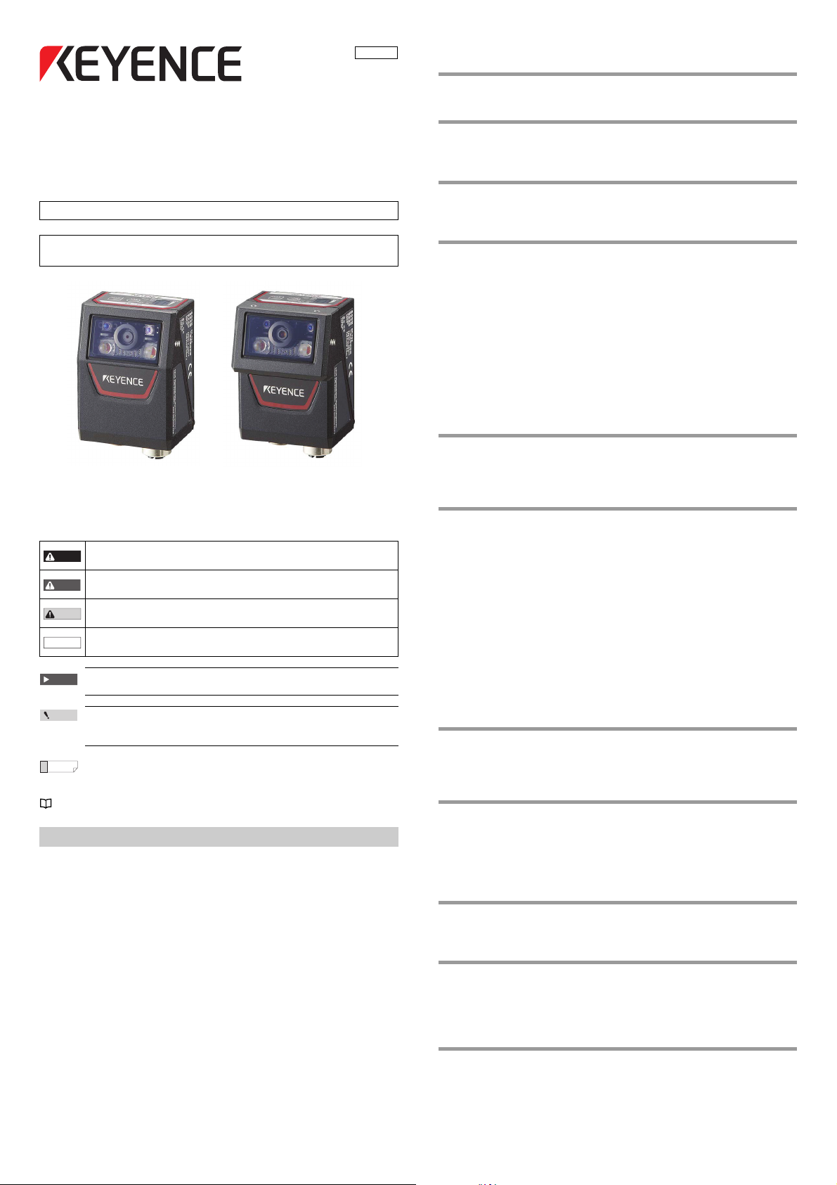
Symbols
This user's manual uses the following symbols that alert you to important
messages. Be sure to read these messages carefully.
It indicates a hazardous situation which, if not avoided, will result
DANGER
in death or serious injury.
It indicates a hazardous situation which, if not avoided, could
WARNING
result in death or serious injury.
It indicates a hazardous situation which, if not avoided, could
CAUTION
result in minor or moderate injury.
It indicates a situation which, if not avoided, could result in
NOTICE
product damage as well as property damage.
Cautions as to operation that is always performed are shown.
Cautions as to operation that can be easily performed incorrectly
are shown.
Matters that will help the user improve understanding of the text and
useful information are shown.
The items and pages to be referred to in this document are shown.
Introduction
This instruction manual describes the connection/wiring procedure, setting
instructions, and precautions for using the "SR-750 Series 2D Code Reader".
Please read this manual thoroughly before using the SR-750 Series to ensure
optimum performance. Keep this manual handy for quick future reference.
1-1 Checking the Package Contents ....................................................... 3
1-2 Part Names and Functions ................................................................ 3
1-3 System Configuration and Setup Flow .............................................. 4
2-1 Connecting the Power Source ........................................................... 6
2-2 Connecting the Control Cable and Wiring ......................................... 6
2-3 Connecting the Ethernet Cable ......................................................... 8
3-1 Using the SR-750 Series ................................................................... 9
3-2 Quick Calibration ............................................................................. 10
3-3 Alternate Function ........................................................................... 11
3-4 Test Mode........................................................................................ 12
3-5 Preset/Verification Function.............................................................14
3-6 Multi-I/O Function ............................................................................ 14
3-7 Image Saving Function.................................................................... 16
3-8 Silent Mode...................................................................................... 18
3-9 SR-600 Compatible Output Mode ...................................................19
3-10 Batch Setting Code.......................................................................... 20
3-11 Code quality verification function..................................................... 20
3-12 Duplicate reading prevention interval reset.....................................24
3-13 Edit data function/Edit image file name function..............................24
4-1 Reading Operations......................................................................... 26
4-2 Timing Mode.................................................................................... 26
4-3 Data Transmission Timing ............................................................... 27
4-4 Read Mode ...................................................................................... 28
5-1 Installing, Starting, and Shutting Down............................................30
5-2 Screen Layout .................................................................................33
5-3 AutoID Network Navigator Operation Flow...................................... 34
5-4 Details of Settings View ................................................................... 34
5-5 Sending/Receiving Configuration.................................................... 49
5-6 Saving/Reading a Configuration File...............................................49
5-7 Quick Setup Code ........................................................................... 50
5-8 Terminal........................................................................................... 50
5-9 LiveView .......................................................................................... 51
5-10 ImageView....................................................................................... 52
5-11 FileView ........................................................................................... 53
5-12 Installation Guide ............................................................................. 53
5-13 Export Reader Configuration ........................................................... 54
5-14 Report Generator Function..............................................................55
5-15 Creating Reports for the SR-750 Series.......................................... 56
6-1 Before Mounting the SR-750 Series................................................60
6-2 Mounting the SR-750 Series ........................................................... 60
6-3 Adjusting the Mounting Position ...................................................... 61
6-4 Confirming the Reading Stability ..................................................... 61
7-1 Communication of the SR-750 Series ............................................. 63
7-2 Data Communication Format........................................................... 63
7-3 RS-232C Communication................................................................67
7-4 Ethernet Communication ................................................................. 68
7-5 Socket Communication.................................................................... 69
7-6 FTP Communication ........................................................................ 69
8-1 Details of Command Communication .............................................. 71
8-2 Operation Commands ..................................................................... 71
8-3 Details of Configuration Commands................................................ 75
9-1 PLC Link .......................................................................................... 85
9-2 Configuration ................................................................................... 85
9-3 Device Assignment.......................................................................... 87
9-4 Reference Program ......................................................................... 90
9-5 PLC Link Error ................................................................................. 91
10-1 Master/Slave function ...................................................................... 92
10-2 Setting procedure ............................................................................92
10-3 Multi drop link mode ........................................................................93
10-4 Multi head mode .............................................................................. 93
1
E SR-750 UM
Page 2
11-1 EtherNet/IP ...................................................................................... 94
WARNING
CAUTION
NOTICE
WARNING
NOTICE
11-2 Cyclic communication...................................................................... 95
11-3 Message Communication..............................................................101
11-4 Reference Program ....................................................................... 105
12-1 PROFINET .................................................................................... 109
12-2 Cyclic communication.................................................................... 109
13-1 Installing MultiMonitor.................................................................... 112
13-2 Using MultiMonitor......................................................................... 113
14-1 Installing FileView.......................................................................... 114
14-2 Using FileView............................................................................... 115
15-1 SR-750 Series Specifications ........................................................ 116
15-2 Dimensions.................................................................................... 117
15-3 SR-750 Series Field of View Size ................................................. 118
15-4 Troubleshooting.............................................................................119
15-5 Checksum Calculation Method...................................................... 121
15-6 ASCII Code List ............................................................................. 121
15-7 Software License ........................................................................... 122
15-8 Precautions on Regulations and Standards..................................122
15-9 Copyright indications ..................................................................... 123
General Precautions
• Do not use this product for the purpose to protect a human
body or a part of human body.
• This product is not intended for use as explosion-proof product.
Do not use this product in a hazardous location and/or
potentially explosive atmosphere.
• Be sure to check that the SR-750 Series performs properly
before starting the work or operation.
• If the SR-750 Series malfunctions, take adequate safety
precautions to prevent various types of damage.
• Do not use the SR-750 Series in a manner not specified herein. It
may result in fire, electric shock or malfunction.
• It should be noted that functions and performances will not be
guaranteed if the SR-750 Series is used in any way not specified
or described in the product specifications or it is modified.
• When the SR-750 Series is used in combination with other
devices, functions and performance may be degraded,
depending on the operating conditions and environment.
Safety Information for SR-750 Series
Safety precautions on Laser product
The SR-750 Series Fixed Mount 2D Code Reader uses a visible semiconductor
laser, with a wavelength of 660 nm, as a Laser pointer for adjusting the reading
position.
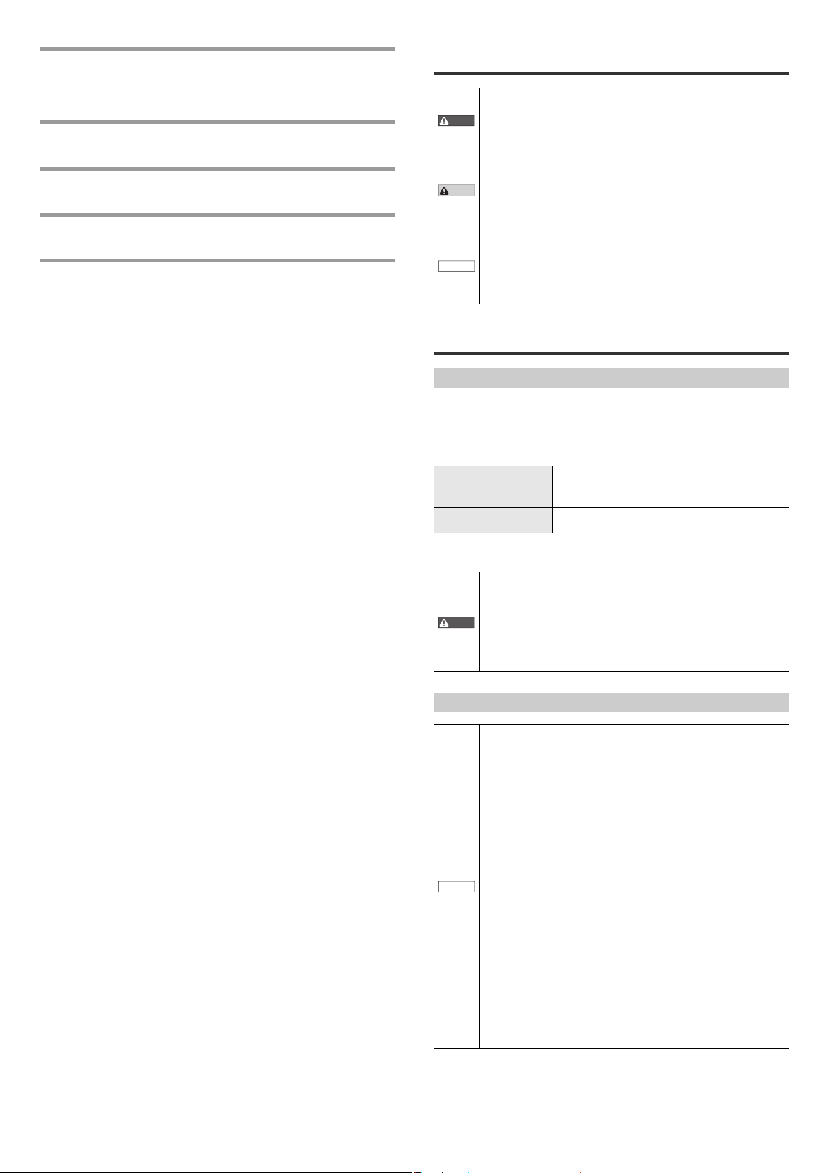
Laser Pointer Specifications
Wavelength 660nm
Output 60μW
Pulse duration 200μs
Laser class
* The classification is based on IEC60825-1 standard following the Laser Notice
No. 50 from FDA (CDRH).
• Use of controls or adjustments or performance of procedures
other than those specified herein may result in hazardous
radiation exposure.
• Do not disassemble this product. The laser radiation emission
from this product is not automatically stopped when it is
disassembled.
Precautions on Class 1 Laser Product
• Do not stare into the direct or specularly reflected beam.
Class 1 Laser Product
(IEC60825-1, FDA(CDRH) Part 1040.10*)
Precautions on Proper Use
• Do not use a voltage other than that described in the
specifications with the SR-750 Series. Doing so may damage to
the unit.
• The SR-750 Series employs 2 power connection methods,
which are 24 V DC supply and supply from PoE power supply
devices. When connecting the SR-750 Series to the power
source, be sure to use one of these methods. Using both power
sources simultaneously may cause damage to the units.
• Be sure to turn off the power to devices attached to the SR-750
Series when you plug in or unplug the cables.
Failure to do so may cause damage to the SR-750 Series.
• Do not disassemble or modify the SR-750 Series. Doing so may
damage to the unit.
• Place cables as far away as possible from high-voltage lines
and power lines. Otherwise, electrical noise can be generated
that may cause product failure or malfunction.
• The SR-750 Series is a precision instrument. Do not impact or
drop the instrument. Pay particular attention when transporting
or installing the unit.
• Do not hold the unit by its cable when carrying. The units may
become damaged if the cables are disconnected or the units
strike each other.
• Do not allow water, oil, dust, or other foreign substances to
stick to the scanner. This may cause read errors.
Use a soft, dry cloth to wipe any substance from the scanner.
(Do not use a cloth dipped in alcohol or other cleaning
substance.)
E SR-750 UM
2
Page 3
1-1 Checking the Package
1
E SR-750-IM
Fixed Mount 2D Code Reader
SR-750 Series
Instruction manual
Read this instruction manual before using the product in order to achieve
maximum performance.
Keep this instruction manual in a safe place after reading it so that it can be
used at any time.
Symbols
The following symbols alert you to important messages. Be sure to read
these messages carefully.
Important
It indicates cautions and limitations that must be followed during operation.
Point
It indicates additional information on proper operation.
Reference
It indicates tips for better understanding or useful information.
indicates the reference pages in this manual or the reference pages in separate manuals.
Safety Information for SR-750 Series
General Precautions
Safety precautions on Laser product
The SR-750 Series Fixed Mount 2D Code Reader uses a visible semiconductor
laser, with a wavelength of 660 nm, as a Laser pointer for adjusting the reading
position.
Laser Pointer Specifications
* The laser classification for FDA(CDRH) is implemented based on
IEC60825-1 in accordance with the requirements of Laser Notice No.50.
Precautions on Proper Use
Precautions on Regulations and Standards
CE Marking
Keyence Corporation has confirmed that this product complies with the
essential requirements of the applicable EC Directive, based on the
following specifications. Be sure to consider the following specifications
when using this product in the Member State of European Union.
zEMC Directive (2004/108/EC)
•Applicable standards EMI : EN61326-1, Class A
EMS: EN61326-1
Remarks:
These specifications do not give any guarantee that the end-product with
this product incorporated complies with the essential requirements of
EMC Directive. The manufacturer of the end-product is solely responsible
for the compliance on the end-product itself according to EMC Directive.
zLow-voltage Directive (2006/95/EC)
•Applicable Standard EN60825-1,
Class 1 Laser Product
EN62471
CSA Certificate
This product complies with the following CSA and UL standards and has
been certified by CSA.
•Applicable standards: CAN/CSA C22.2 No.61010-1
UL61010-1
Be sure to consider the following specifications when using this product as a
product certified by CSA.
•Overvoltage category
•Use this product under pollution degree 3.
•Use this product at the altitude of 2000 m or less.
•Indoor use only.
•When using this product, use the following power supply.
•CSA or UL certified power supply that provides Class 2 output as defined
in the CEC (Canadian Electrical Code) and NFPA79 (NEC: National
Electrical Code), or
•CSA or UL certified power supply that has been evaluated as a Limited
Power Source as defined in CAN/CSA-C22.2 No. 60950-1/UL60950-1.
•Either PoE or 24V power supply shall be used.
•The symbol on the product means "Direct current".
FDA (CDRH) Regulations
This product complies with the following FDA (CDRH) regulations.
•FDA(CDRH) Part 1040.10, Class 1 Laser Product
The laser classification for FDA(CDRH) is implemented based on IEC608251 in accordance with the requirements of Laser Notice No.50.
FCC Regulations
This product complies with the following FCC EMI regulations.
•FCC Part 15 Subpart B, Class A Digital Device
IC (Industry Canada) Regulations
This product complies with the following IC EMI regulations.
•ICES-003, Class A Digital Apparatus
It indicates a hazardous situation which, if not avoided, will result in death or
serious injury.
It indicates a hazardous situation which, if not avoided, could result in death
or serious injury.
It indicates a hazardous situation which, if not avoided, could result in minor
or moderate injury.
It indicates a situation which, if not avoided, could result in product damage
as well as property damage.
•Do not use this product for the purpose to protect a human body or a part
of human body.
•This product is not intended for use as explosion-proof product. Do not
use this product in a hazardous location and/or potentially explosive
atmosphere.
•Be sure to check that the SR-750 Series performs properly before starting
the work or operation.
•If the SR-750 Series malfunctions, take adequate safety precautions to
prevent various types of damage.
•Do not use the SR-750 Series in a manner not specified herein. It may
result in fire, electric shock or malfunction.
•It should be noted that functions and performances will not be guaranteed
if the SR-750 Series is used in any way not specified or described in the
product specifications or it is modified.
•When the SR-750 Series is used in combination with other devices,
functions and performance may be degraded, depending on the operating
conditions and environment.
Wavelength 660nm
Output 60PW
Pulse duration 200Ps
Laser class
Class 1 Laser Product
(IEC60825-1:2007, FDA(CDRH) Part 1040.10*)
•Use of controls or adjustments or performance of procedures other than
those specified herein may result in hazardous radiation exposure.
•Do not disassemble this product. The laser radiation emission from this
product is not automatically stopped when it is disassembled.
Precautions on Class 1 Laser Product
•Do not stare into the direct or specularly reflected beam.
96M12458
DANGER
WARNING
CAUTION
NOTICE
WARNING
CAUTION
NOTICE
WARNING
•Do not use a voltage other than that described in the specifications with
the SR-750 Series. Doing so may damage to the unit.
•The SR-750 Series employs 2 power connection methods, which are 24 V
DC supply and supply from PoE power supply devices. When connecting
the SR-750 Series to the power source, be sure to use only one of these
methods. Using both power sources simultaneously may cause damage
to the units.
•Be sure to turn off the power to devices attached to the SR-750 Series
when you plug in or unplug the cables.
Failure to do so may cause damage to the SR-750 Series.
•Do not disassemble or modify the SR-750 Series. Doing so may damage to
the unit.
•Place cables as far away as possible from high-voltage lines and power
lines. Otherwise, electrical noise can be generated that may cause product
failure or malfunction.
•The SR-750 Series is a precision instrument. Do not impact or drop the
instrument. Pay particular attention when transporting or installing the
unit.
•Do not hold the unit by its cable when carrying. The units may become
damaged if the cables are disconnected or the units strike each other.
•Do not allow water, oil, dust, or other foreign substances to stick to the
scanner. This may cause read errors.
Use a soft, dry cloth to wipe any substance from the scanner. (Do not use
a cloth dipped in alcohol or other cleaning substance.)
NOTICE
TEST
TUNE
POW
ERR
NET
IN
STB
OK/NG/
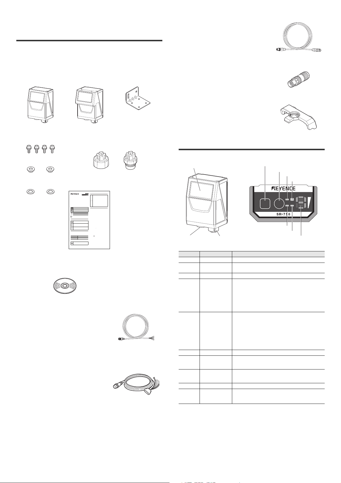
(4) TEST button
(5) TUNE button
(6) POW LED
(7) OK/NG/ERR LED
(8) NET LED
(9) IN LED
(10) Multiple LED indicator
(1) Scanner
(2) Power supply and
control port
(3) Ethernet port
Contents
The packages of the SR-750 Series main units and the SR-750 Series
configuration software contain the following components.
Check that you have all the package contents before use.
SR-750 Series (Fixed mount 2D code reader)
Main unit
SR-750/751/750HA SR-752
Mounting screw (M4) x 4 Port cover (Power supply and control port,
Ethernet connection port) x 1 each
Mounting bracket x 1
NFPA79 compliant Ethernet cable
• OP-87359 (2 m cable)
• OP-87360 (5 m cable)
• OP-87361 (10 m cable)
Ethernet assembly plug
• OP-87362
Long distance lens
400 mm lens
• SR-75L4
600 mm lens
• SR-75L6
1-2 Part Names and Functions
Insulating spacer x 2
Washer x 2 Instruction Manual
SR-H3W
AutoID Network Navigator
Cable and connector
Control cable (Power supply, I/O, RS-232C)
• OP-87224 (2 m cable)
• OP-87225 (5 m cable)
• OP-87226 (10 m cable)
NFPA79 compliant Control cable
• OP-87353 (2 m cable)
• OP-87354 (5 m cable)
• OP-87355 (10 m cable)
Control cable (NFPA79-compliant) with D-Sub9 pin
(Power supply, I/O, RS-232C)
• OP-87527 (2 m cable)
• OP-87528 (5 m cable)
• OP-87529 (10 m cable)
This section describes the part names and functions of the SR-750 Series.
Number Name Function
(1) Scanner Reads 2D codes and bar codes.
Power supply and
(2)
control port
(3) Ethernet port Connect the Ethernet cable.
(4) TEST button
(5) TUNE button
(6) POW LED When the power is turned ON, the "green" light turns on.
(7) OK/NG/ERR LED
(8) NET LED
(9) IN LED When an input terminal is on, this lights up.
(10)
Multiple LED
indicator
Connect the control cable.
Use this button to perform the following operations:
• Run 1 reading operation.
• Start and stop test mode.
• Run the multi-reading mode.
• Fix the communication settings of RS-232C to the default
values.
• Reset PLC link error.
Use this button to perform the following operations:
• Turn on the laser pointer for reading position adjustment.
• Start parameter tuning.
• Display the number of parameter banks of which the
alternate function is effective.
• Read the quick setup code.
• Reset errors.
• Start Ethernet communication BootP mode connection.
• When OK output is ON, the "green" light turns on.
• When NG output is ON, the "orange" light turns on.
• When ERR output is ON, the "red" light turns on.
• When connected to Ethernet, the "green" light turns on.
• When the Ethernet data is sent/received, the "green" light
turns on.
This displays the operation status including the bank
number upon successful reading, reading stability and
operation mode.
300GB
3
E SR-750 UM
Page 4
Operation status on the multiple LED indicator
Numeric
value
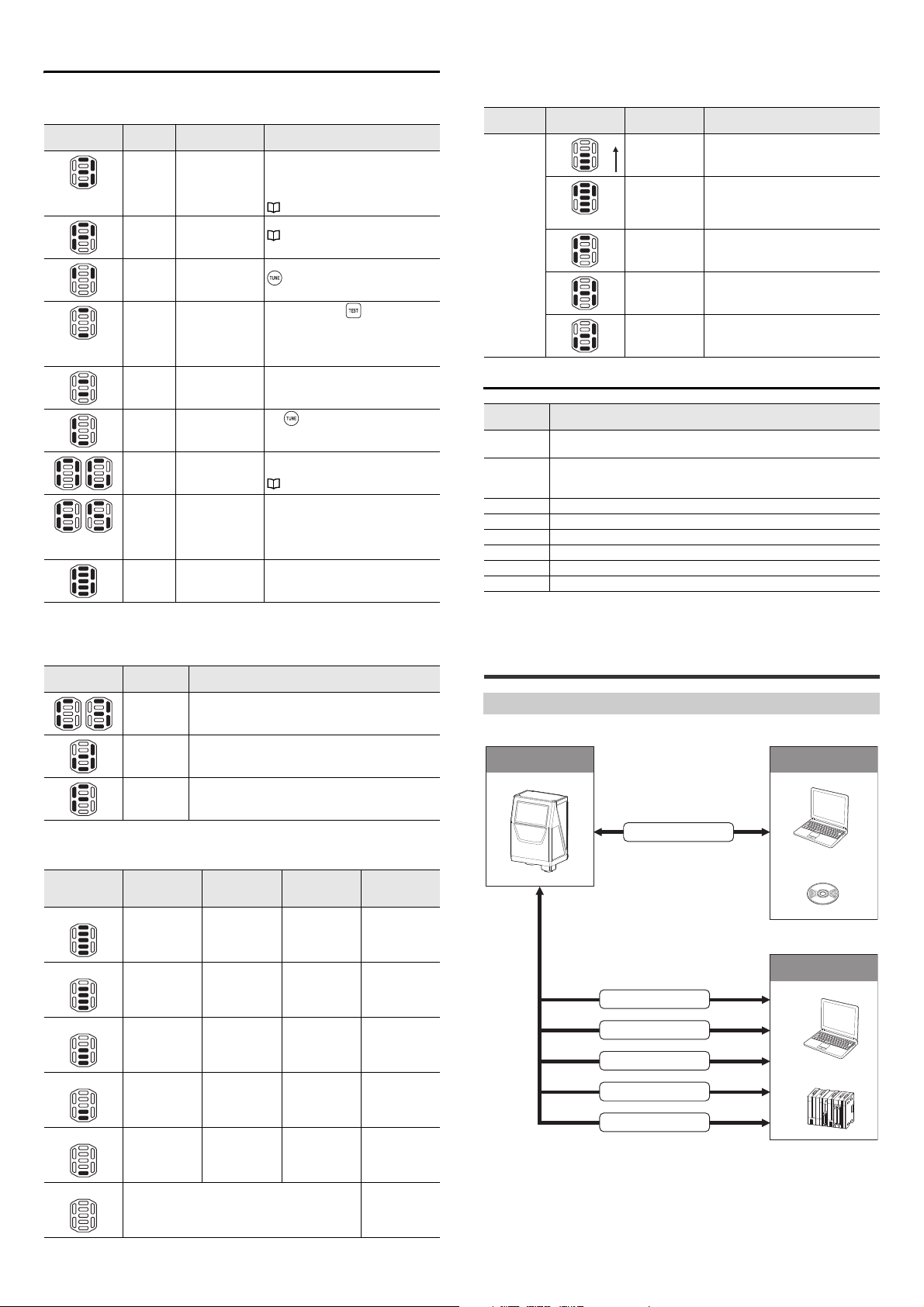
SR-750 Series Setup PC
Ethernet
AutoID Network
Navigator
Host
PC
PLC
Ethernet
EtherNet/IP
RS-232C
I/O terminal
PROFINET
Run mode
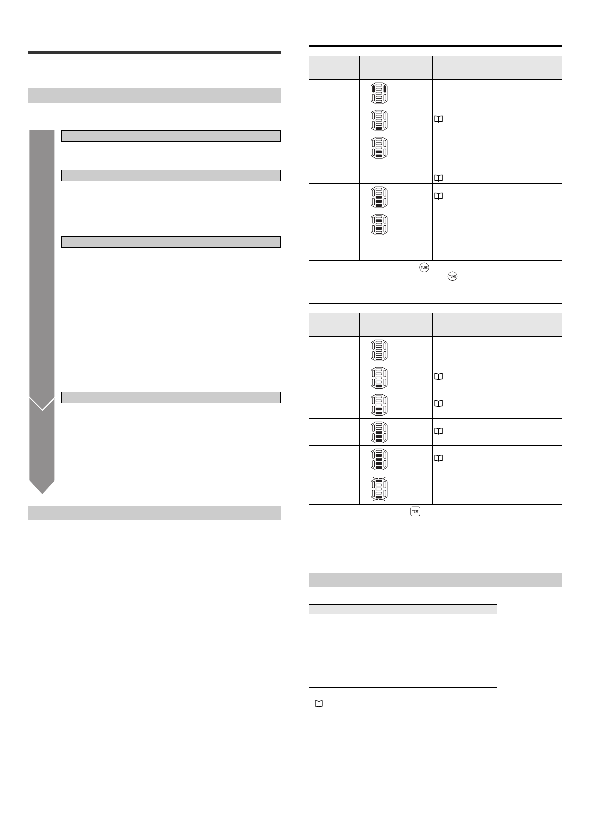
In Run mode, the multiple LED displays a number, letter, or other symbol.
Multiple LED
indicator
Display
content
0 to 10 When reading
P Preset Preset successful
2 points
light up
2 points
flashing
2 points
flashing
L TUNE button lock
NG Saving the read
←→
E
Error code
All LEDs
light up
Operation Meaning
successful
Laser pointer
emission
Set the
communication
parameters of the
RS-232C to the
default state.
Temporary IP
address setting
mode
error image
Error occurred. This shows that an error, such as buffer
At power-on All LEDs light up for 500 ms when the
The parameter bank number is displayed
(1 to 10).
When the parameter bank is 10, the first
digit value and "1" are displayed alternately.
"3-3 Alternate Function (Page 11)"
"3-5 Preset/Verification Function
(Page 14)"
The laser pointer is turned on when the
button is pressed quickly.
Press and hold the button for at least
6 seconds. The LED flashes and the RS232C communication condition returns to
the factory default state.
Press the TUNE button for at least 5
seconds. The LED flashes in the
temporary IP address setting mode.
The button is locked according to the
settings. The laser pointer cannot be turned
on and quick calibration cannot be performed.
The LED lights up while the read error
image is being written into the ROM.
"3-7 Image Saving Function (Page 16)"
over or IP address duplication has
occurred.
E and error code (number) lights up
alternately.
power is turned on.
Other operations
In the quick calibration operation, the multiple LED displays bars, a number, or a
letter.
Action
Quick
calibration
Multiple LED
indicator
Display content Meaning
Bar LEDs light up
in series.
Bar LEDs and
upper 2 points
light up.
This shows the progress of the quick
calibration.
The quick calibration is complete and the
test mode is running. Changing the
position of the code fluctuates the bar
LEDs.
Quick calibration failed
(Data for successful quick calibration was
F
not provided.)
Quick calibration failed
(Data for successful quick calibration was
H
provided.)
Saving complete
d
Error indications on the multiple LED indicator
Display
content
E0, E1
Main unit system error
* Abnormal operation of the main unit. Contact your nearest KEYENCE office.
Configuration file reading error, image save error
E2
* If the operation is not restored even after the main unit is initialized, there may
be problems with the main unit . Contact your nearest KEYENCE office.
E3 PROFINET error
E4 Transmission buffer overflow
E5 IP address duplication error
E6 Main unit system firmware update error
E7 PLC link error
E8 Script error
Description
Quick setup code reading mode
In Quick setup code reading mode, the multiple LED displays a number, alphabet,
etc.
Multiple LED
indicator
←→
C
Display
content
d
F
Meaning
C: Starts reading the quick setup code.
Numeric value: The number "C" of quick setup codes being
read and the numeric value are displayed alternately.
Reading successful or program successful
Reading failed or program failed
Test Mode
In Test mode, the multiple LED displays measurement results.
Multiple LED
status
5 bars lit
4 bars lit
3 bars lit
Reading rate
measurement
(%)
90 to 100 Up to 99 LEVEL 5 Green
70 to 80 100 to 199 LEVEL 4 Green
50 to 60 200 to 299 LEVEL 3 Green
Processing time
(ms)
Position
OK/NG/ERR
1-3 System Configuration and
Setup Flow
System configuration
The SR-750 Series has the following configuration.
LED
2 bars lit
1 bar lit
0 bars lit
E SR-750 UM
30 to 40 300 to 399 LEVEL 2 Green
10 to 20 400 or more LEVEL 1 Green
Reading error Red
4
Page 5
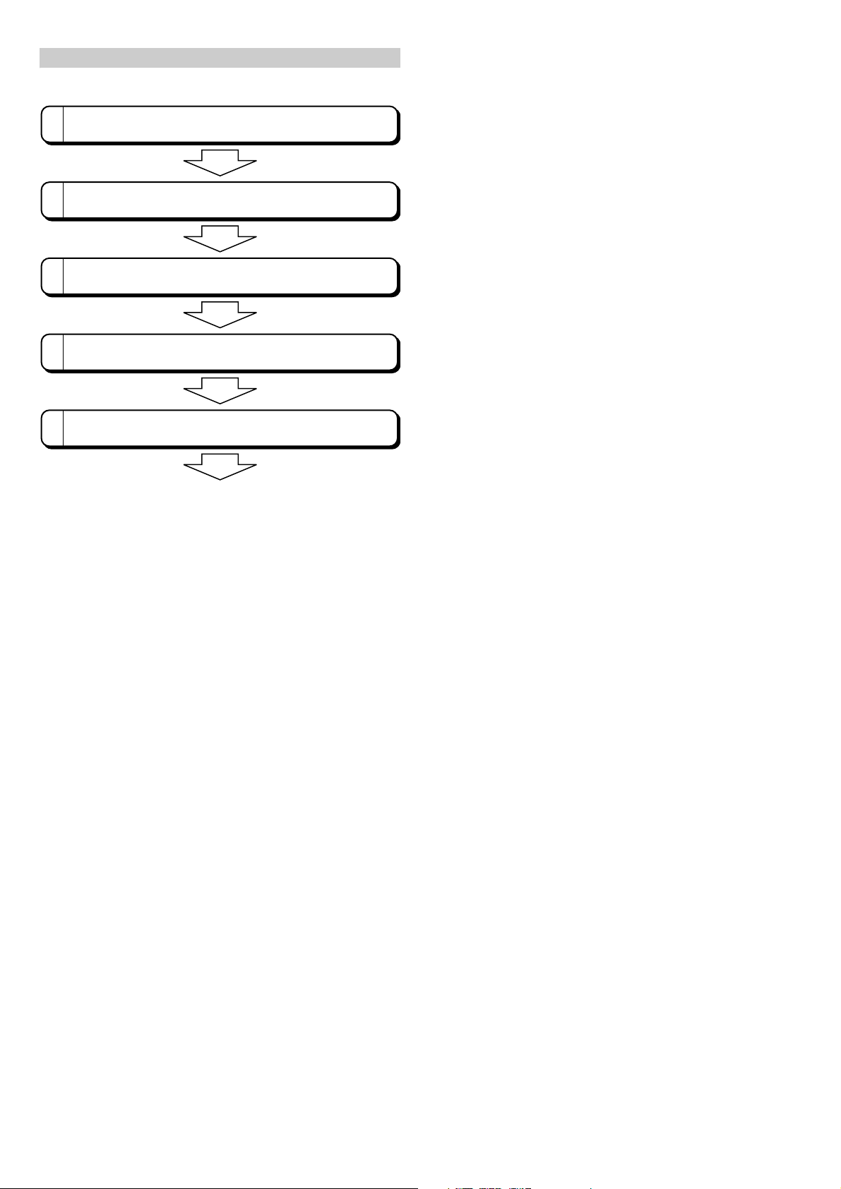
Setup Flow
After unpacking the package, first check the package contents.
1
Start operation.
Connect the SR-750 Series to a communication unit or a PC.
2
Use the AutoID Network Navigator to configure and send settings to the
SR-750 Series.
3
Install the SR-750 Series according to the location.
4
Adjust the reading conditions and make the operation settings of the SR750 Series.
5
This section describes the flow of the setup procedure required for starting the
operation of the SR-750 Series.
5
E SR-750 UM
Page 6
2-1 Connecting the Power
NOTICE
+24 V
+
24 V DC ±10%
Brown
0 V Blue
SR-750 Series HUB compatible with PoE power supply
Ethernet cable for the
SR-750 Series
NOTICE
NOTICE
Align the notch with the
marking position.
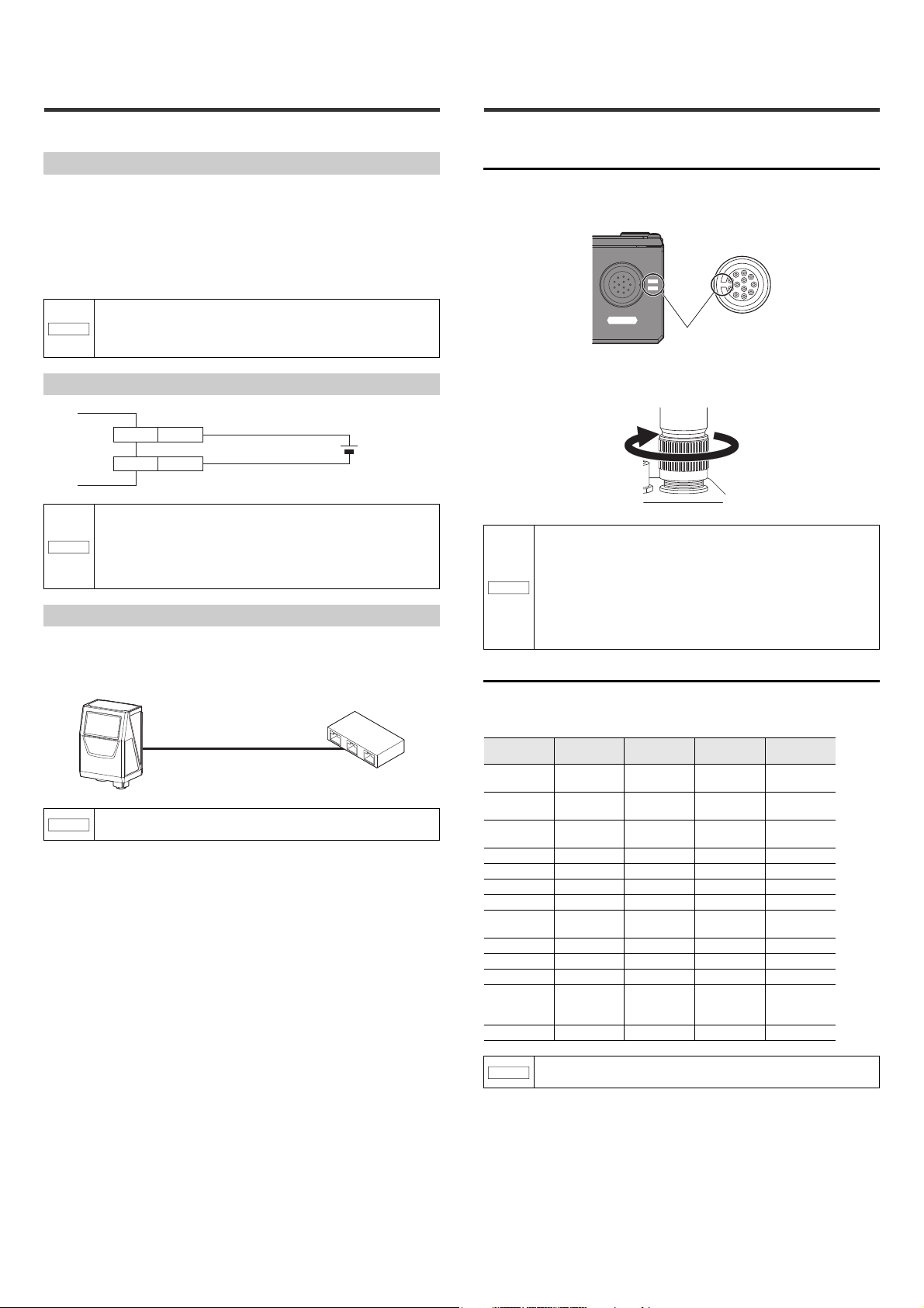
2-2 Connecting the Control
Source
This section describes how to connect the SR-750 Series and the power source.
Power supply to the SR-750 Series
There are 2 methods employed for connecting power source to the SR-750 Series.
• Connect the power supply wire of the control cable to a 24 V DC power supply
device.
• Connect to a PoE (Power over Ethernet) power supply device using the Ethernet
port.
Use only one of the above methods to connect to the power source according to
the usage.
Make sure to use either one of the connection methods for power
supply.
NOTICE
If power is supplied both from the control cable and PoE power
supply device at the same time, the unit may be damaged.
Wiring when supplying 24 V to the control cable
• Use a steady power supply voltage of 24 V DC ±10%.
• Do not use a power supply other than 24 V DC. Otherwise, it
may cause failure.
• Before connecting or disconnecting cables, make sure to turn
off power to the equipment connected to the SR-750 Series.
Otherwise, it may cause the failure of the SR-750 Series.
Connection when supplying power from a PoE device
Use the Ethernet cable for the SR-750 Series for connection. Connect the RJ-45
connector of the Ethernet cable to a device (switching hub, etc.) compatible with
the PoE power supply feature.
Cable and Wiring
Connect the control cable to the SR-750 Series.
Control cable connection method
1 Align the dent of the cable connector with the marking position next
to the control port.
POWER
2 Tighten the connector screw by turning clockwise. Set the screw
tightening torque to 1.5 - 2.0 N•m.
When connecting the connector, insert it not to lean toward one
side and securely tighten it. Under-tightening can lead to loose
connector due to vibrations, resulting in poor contact.
Insufficient tightening may not meet the requirements of the
protective structure.
* To get a rough idea, after tightening it by hand, retighten it
approximately 90° - 120° using a tool such as pliers.
Do not repeatedly bend the root of the connector of control cable.
Loose connection may result.
Control cable color and the meaning of signal
Be sure to connect with a PoE power supply device compliant
NOTICE
with IEEE802.3af.
The following different color lead wires are drawn out of the control cable. Solder
the lead wire to the connector using the wire attached to the device to be
connected.
Wire color Symbol Description
Brown 24 V
Blue 0 V
Orange RXD
Yellow TXD RS-232C Send Output 28
Purple SGND RS-232C GND – 28
Green IN1 IN1 Input Input 26
Gray IN2 IN2 Input Input 28
White and blue INCOM
Pink OUT1 OUT1 Output Output 28
Aqua blue OUT2 OUT2 Output Output 28
White OUT3 OUT3 Output Output 28
Black OUTCOM
Black tube FG FG – –
Make sure to turn the power off when attaching or removing the
control cable.
+24 V power
supply
Power supply
GND
RS-232C
Receive
Input common
mode voltage
Output
common mode
voltage
Signal
direction
Input 26
–26
Input 28
–28
–28
AWG si ze
E SR-750 UM
6
Page 7
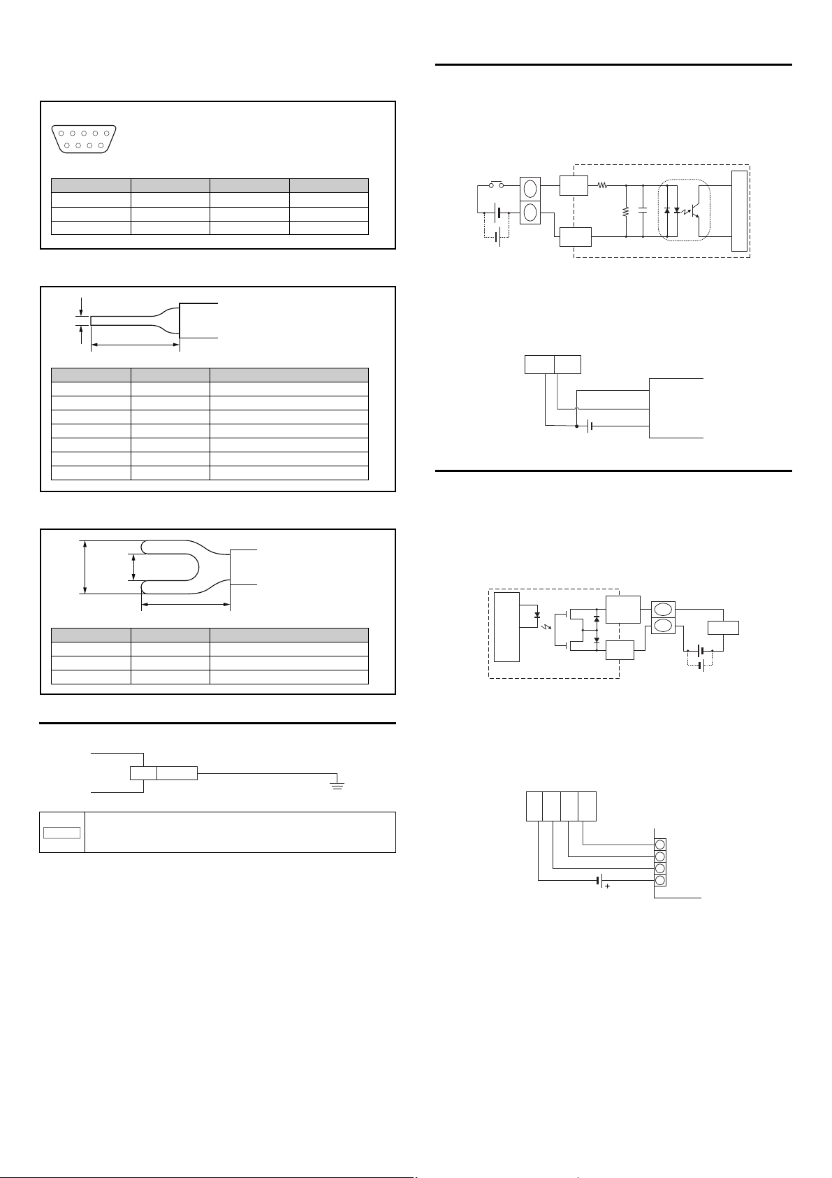
Control cable (NFPA79-compliant) with D-Sub9 pin
D-sub9 pin (Female)
DTE specifications (Terminal definition)
M2.6 screw
54321
9876
Pin No. Symbol Description Signal direction
2 TXD Data Send Output
3 RXD Data Receive Input
5 SGND Signal GND -
Wire color Symbol Description
Green IN1 IN1 Input
Gray IN2 IN2 Input
White and blue INCOM Input common
Pink OUT1 OUT1 Output
Aqua blue OUT2 OUT2 Output
White OUT3 OUT3 Output
Black OUTCOM Output common
1 mm
10 mm
Wire color Symbol Description
Brown 24 V +24 V Power supply
Blue 0 V Power supply GND
Black tube FG FG
6.6 mm
11 m m
4.3 mm
FG Black tube
10kΩ
+
5.6kΩ
Photocoupler isolation
Contact
or
non-contact
Internal circuit
IN1 (Green)
IN2 (Gray)
INCOM
(White and blue)
IN1
(Green)
INCOM
(White and blue)
Brown (red)
Black (white)
Blue (black)
Photoelectric Sensor (NPN)
0002
0001
0000
C
PLC
OUT
COM
(Black)
OUT
1
(Pink)
OUT
2 (Aqua
blue)
OUT
3
(White)
z RS-232C wire
The tip of the RS-232C wire is a D-sub9-pin.
IN1/IN2 wire connection
• The IN1 (timing) input means the input that causes the SR-750 Series to start
reading.
• The IN2 (preset) input means the input that causes the SR-750 Series to register
preset data.
IN1/IN2 inputs operate by voltage inputs.
z Control wire (Input/Output signal wire)
The tip of the control wire is a rod terminal.
z Power wire
The tip of the power wire is a Y-shape terminal.
• Input rating : 15 - 26.4 V DC
• Repetitive peak off-state current : 0.2 mA
Connecting a photoelectric sensor manufactured by
KEYENCE
Connection example when the IN1 terminal is used as the trigger input terminal.
Connecting the OUT1/OUT2/OUT3 wires
• The OUT1 (OK) output is used as an output for successful reading and
verification of OK as a result of checking against the preset data.
• The OUT2 (NG/ERROR) output is used as an output for reading failure and
verification of NG reading as a result of checking against the preset data.
• OUT3 (BUSY) is output any time the trigger input cannot be accepted. For
example, a busy signal will be output at initial start-up, during the key operation,
reading operation, etc.
The output form of each signal is photo MOS relay.
Internal circuit
OUT 1(Pink),
OUT2 (Aqua blue),
OUT3 (White)
OUT COM
(Black)
Load
+
Connecting the FG wire
Be sure to provide Class D ground for the FG wire.
The shield and FG wire of the control cable and the shield of the
Ethernet cable are electrically connected via the main unit case.
NOTICE
Provide them with a common ground.
• Maximum rated load : 30 V DC (1 output maximum 50 mA, 3 outputs
total 100 mA or less)
• Leakage current when OFF : 0.1 mA or less
• Residual voltage when ON : 1 V or less
Connection with KEYENCE PLC (Programmable
controller)
7
E SR-750 UM
Page 8
Wiring the RS-232C signal line
PC SR-750 Series
D-Sub 9 pin
(female)
#4-40 screw
Yel lo w
Orange
Purple
3
5
RD
SD
TxD
SGND
RxD
4SG
Handheld programmer SR-750 Series
Modular
Connector
Yel l ow
Orange
Purple
2
7
3
8
4
5
6
RD
RS
SD
CS
ER
SG
DR
TxD
SGND
RxD
KV-L20V/L20R (Port 1)
KV-N10L
SR-750 Series
D-Sub 9 pin
(female)
#4-40 screw
Yel lo w
Orange
Purple
KV-L20V/L20R (Port 2) SR-750 Series
Yellow
Orange
Purple
2
3
5
8
4
7
1
6
RD
SD
RS
CS
ER
DR
SG
CD
TxD
SGND
RxD
QJ71C24N/-R2 SR-750 Series
D-Sub 9 pin
(male)
M2.6 screw
Yellow
Orange
Purple
SD
RD
RS
CS
SG
TxD
SGND
RxD
2
3
4
5
9
PLC SR-750 S eries
D-Sub 9 pin
(male)
M2.6 screw
Yellow
Orange
Purple
N-R4 SR-750 Series
Round connector
12-pin
(male)
Yel l ow
Orange
Purple
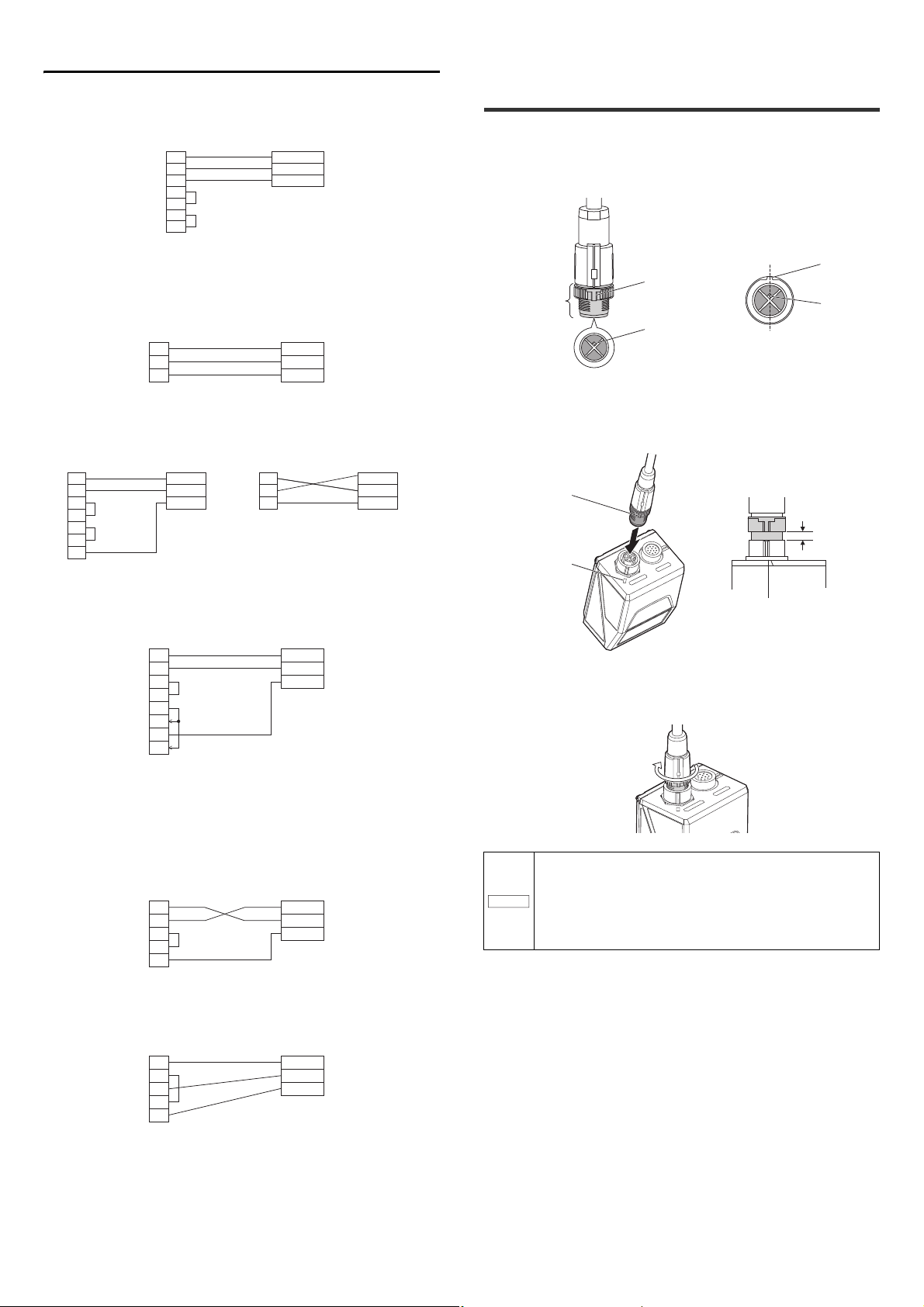
NOTICE
protrusion
positioning pin
connector screw
View from the connector side
protrusion
positioning pin
Rotate the connector screw so that the
protrusion and the positioning pin come
to the above position.
Approx. 4 mm of clearance remains when
inserted fully.
Approx. 4 mm
white mark
protrusion
POWER
ETHERNET
Connect to host devices (PC, PLC, etc.) as illustrated below:
Connection to a PC
2
RxD
TxD
GND(SG)
RTS
CTS
DTR(ER)
DSR(DR)
3
5
7
8
4
6
TxD
RxD
SGND
Connection to the handheld programmer for the
KEYENCE KV Series
Connection to the KV-L21V/L20V/L20R/N10L
2-3 Connecting the Ethernet
Cable
Connect the Ethernet cable to the SR-750 Series in the following procedure.
1 Preparation of Ethernet cable
First, rotate the connector screw and align the protrusion position with the
positioning pin position in the connector.
2 Connect to the SR-750 main unit
Align the protrusion position of the connector screw with the white mark
position of the SR-750 Series Ethernet port. Then, insert straight to avoid tilting
the connector.
3
SD
5
RD
1
SG
Connection to the QJ71C24N/-R2
Connection to the SYSMAC Series PLC
CJ1W-SCU(-V1)
CS1W-SCU-V1
CS1W-SCB-V1
CP1W-CIF01
TxD
RxD
SGND
POWER
ETHERNET
3 Tighten the connector
Rotate the connector screw in the arrow direction until it stops (approx. 180
degrees) and tighten it.
• When connecting the connector, insert it straight so it does not
tilt. Otherwise, the connector pin may be damaged.
• Tighten the connector screw correctly. If it is not tightened
properly, the connector may become loose due to vibration, etc.
and connection failure may occur.
• Do not repeatedly bend the root of the connector of Ethernet
cable. Loose connection may result.
Wiring with the N-R4 Series
RD
RS
SD
CS
GND
E SR-750 UM
3
4
7
8
12
TxD
RxD
SGND
8
Page 9
3-1 Using the SR-750 Series
Preparations
Start of
Operation
TUNE Button Operation Procedure
This section describes basic uses for performing reading operation using the SR750 Series.
Basic steps
Before using the SR-750 Series, register codes and conduct read test by
performing the following steps:
(1) Read condition setting
Perform the quick calibration on the SR-750 Series.
• 3-2 Quick Calibration
• 5-4 Details of Settings View
(2) Read test
Once the quick tuning is complete, confirm that reading is stable.
Using the test mode of the SR-750 Series, confirm the reading
stability and the read processing time.
• 3-1 Using the SR-750 Series (TEST Button Operation).
• 3-4 Test Mode
• 5-8 Terminal
(3) Determination of operation
Let's consider the usage of the SR-750 Series.
The SR-750 Series has functions that lead to stable operation or
reduction in control man-hours.
Function leading to stable read
• 3-3 Alternate Function
• SR-750 Series Operations
Function leading to reduction in control man-hours
• 3-5 Preset/Verification Function
• 3-6 Multi-I/O Function
• 3-8 Silent Mode
• Edit data function and edit image file name function
• Duplicate reading prevention interval reset
• Master/Slave function
Connection method with a control device
• Connection and Wiring
• SR-750 Series Communication Specifications
(4) Start of Operation
Once the operation procedure and installation conditions have been
determined, you can start the operation.
The SR-750 Series has the functions that are useful for analyzing
read errors, etc. that occur during operation.
• Matching function
• 3-11 Code quality verification function
• 3-7 Image Saving Function
• 7-2 Data Communication Format
• 7-6 FTP Communication
Multiple
Operation
Press once
quickly
(less than 1 s)
Press for 2
seconds
Press for 3
seconds
Press for 4
seconds
Press for 5
seconds
indicator
LED
Lighting Action
The laser pointer emits a laser beam.
(Reading is disabled while the laser pointer is
on.)
Illuminates
Illuminates
Illuminates
Illuminates
Activates the quick calibration function.
1 time
2 times
3 times
3 times
"3-2 Quick Calibration (Page 10)"
The number of parameter banks (0 to 10) for
which the alternate function can be used is
shown on the multiple LED indicator. When the
number of registered parameter banks is 10, "0"
and "1" are displayed alternately.
"3-3 Alternate Function (Page 11)"
Activates the batch setting reading mode.
"3-10 Batch Setting Code (Page 20)"
Activates the temporary IP address setting
mode.
* Only in this mode, the operation does not
finish even if the TUNE button is briefly
pressed once. Assign the temporary IP
address or turn the power on again.
* To quit an action/mode, press the button once briefly.
To quit the quick calibration, hold down the button for at least 2 seconds.
TEST Button Operation Procedure
Multiple
Operation
Press once
quickly
(less than 1 s)
Press for 2
seconds
Press for 3
seconds
Press for 4
seconds
Press for 5
seconds
Press for 6
seconds
indicator
LED
Lighting Action
Illuminates
Illuminates
Illuminates
Illuminates
Illuminates
Illuminates
One reading operation is performed.
Activates the reading rate test mode.
1 time
2 times
3 times
4 times
5 times
"Reading rate test mode" (Page 12)
Activates the tact measurement test mode.
"Read time test mode (Page 13)"
Activates the bar code position test mode.
"Code position measurement test mode"
(Page 13)
Runs the multi 1 read mode.
"4-4 Read Mode (Page 28)"
Sets the communication settings of RS-232C to
the default state temporarily.
SR-750 Main Unit Buttons
The SR-750 Series main unit has 2 buttons for registering and adjusting the
reading operation.
• TUNE button : used for turning on the laser-aimer, starting quick calibration and
• TEST button : used for starting the test mode and changing the RS-232C
According to the operating status of each button, the status is also displayed on the
multiple LED.
This section describes the operation procedure of the 2 buttons.
reading the quick setup code
communication settings to the default condition.
* To quit an operation, press the button once briefly.
* The default state of the RS-232C communication settings is as follows.
• The default settings for the RS-232C communication
Baud rate : 115200 bps Header : None
Data bits : 8 bit Terminator : CR
Parity : Even Stop bit length : 1 bit
Operation of I/O terminals
The default settings of the I/O terminals of the SR-750 Series are as follows:
Terminal Function
Input terminal IN1 Trigger input
Output terminal OUT1 OK
IN2 Preset input
OUT2 NG/ERROR
OUT3 TRG BUSY
LOCK BUSY
MODE BUSY
ERR BUSY
* Functions of each terminal can be changed according to the settings.
"3-6 Multi-I/O Function (Page 14)"
9
E SR-750 UM
Page 10
3-2 Quick Calibration
TEST TUNE
SR-625
POWERR
NET IN
STB
OK/NG/
Focal distance : SR-750H A : 38 mm
SR-750 : 60 mm
SR-751 : 100 mm
SR-752 : 250 mm
Illuminating LEDs
increase upward.
Reading rate
Test result display
Illuminates
Flash alternately
Flash alternately
Parameter bank No.
Indicates whether the
initial settings have
been changed or not.
Green: Not changed.
Red: Changed
Illuminates in green
Illuminates in red
This section describes the Quick Calibration function.
Quick Calibration
The SR-750 Series automatically adjusts parameters for reading the target codes
through the main unit button operation or AutoID Network Navigator and store the
settings in its internal memory.
This function is called "Quick Calibration".
Set the calibration condition by using AutoID Network Navigator or sending the
setting commands.
Setting items of calibration conditions
• Camera settings
Set the brightness adjustment mode, exposure on high speed mode, offset and
dynamic range.
• Tuning options
Set the tuning method, multi read and inverse read.
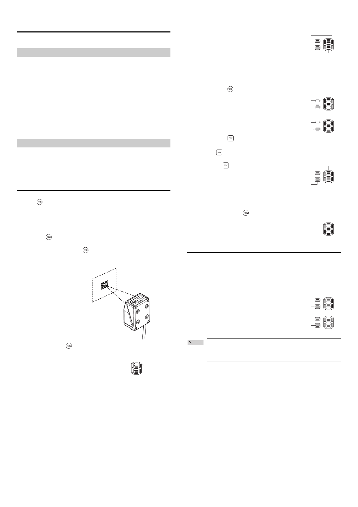
Quick Calibration Function Operation
The following are the quick calibration methods.
• Using the main unit buttons
• Using the input terminal
• Using AutoID Network Navigator
Each operation method is described.
Activation using the button on the panel
Use the button on the panel of the SR-750 Series to activate the quick calibration.
When the button is held down for 2 seconds in Quick Calibration mode, the
quick calibration is canceled and the SR-750 Series returns to Run mode.
1 Set up the SR-750 Series and prepare the code that is going to be
read.
2 Press the button quickly to start the laser pointer emission and
adjust the reading position.
After the adjustment, press the button quickly to turn off the laser pointer.
* When SR-75L4 or SR-75L6 is attached, the emission of the laser pointer is
not visible.
4 After the calibration, the reading rate measurement is performed
automatically.
Once the calibration finishes successfully, the
SR-750 Series starts the reading rate
measurement.
Check the level of reading stability on the
multiple LED indicator.
If the reading failure continues for a certain period of time, the quick calibration
is performed again.
If the calibration fails, "F" or "H" is displayed
By pressing the button, you can perform the quick calibration again.
• F: Displayed when the quick calibration
failed.
• H: Displayed when the quick calibration was
completed successfully but the reading
failed and another quick calibration was
attempted but failed.
By pressing the button, you can register
the result of the successful calibration.
5 Press the button and select the parameter bank in which to
register the parameters.
Every time the button is pressed, the
parameter bank number changes by one.
When the initial settings have been changed
for the parameter bank being displayed, the
OK/NG/ERROR LED illuminates in red.
When the parameter bank number is 10, "0"
and "1" are displayed alternately.
6 When the parameter bank in which to register the parameters is
determined, press the button to register the parameters.
When the parameters are registered
successfully, the multiple LED indicator
shows "d".
Activation using the input terminal
By assigning "Quick Calibration Operation" to an input terminal, you can use that
terminal to activate the quick calibration.
1 Turn on the input terminal to which the function has been assigned.
The quick calibration starts.
2 "1" is displayed.
Parameter bank 1 is overwritten with the
calibration result and the TUNING OK output
turns on.
When the calibration fails, the OK/NG/ERROR
LED illuminates in red, the ERROR signal is
output, and the calibration operation ends.
3 Press and hold the button for two seconds to perform quick
calibration.
During the quick calibration, the multiple
LED indicator illuminates as shown on the
right.
E SR-750 UM
Point
When the input terminal is used to activate the quick calibration,
the calibration result is automatically written to parameter bank
No. 1.
3 Turn off the input terminal.
10
Page 11
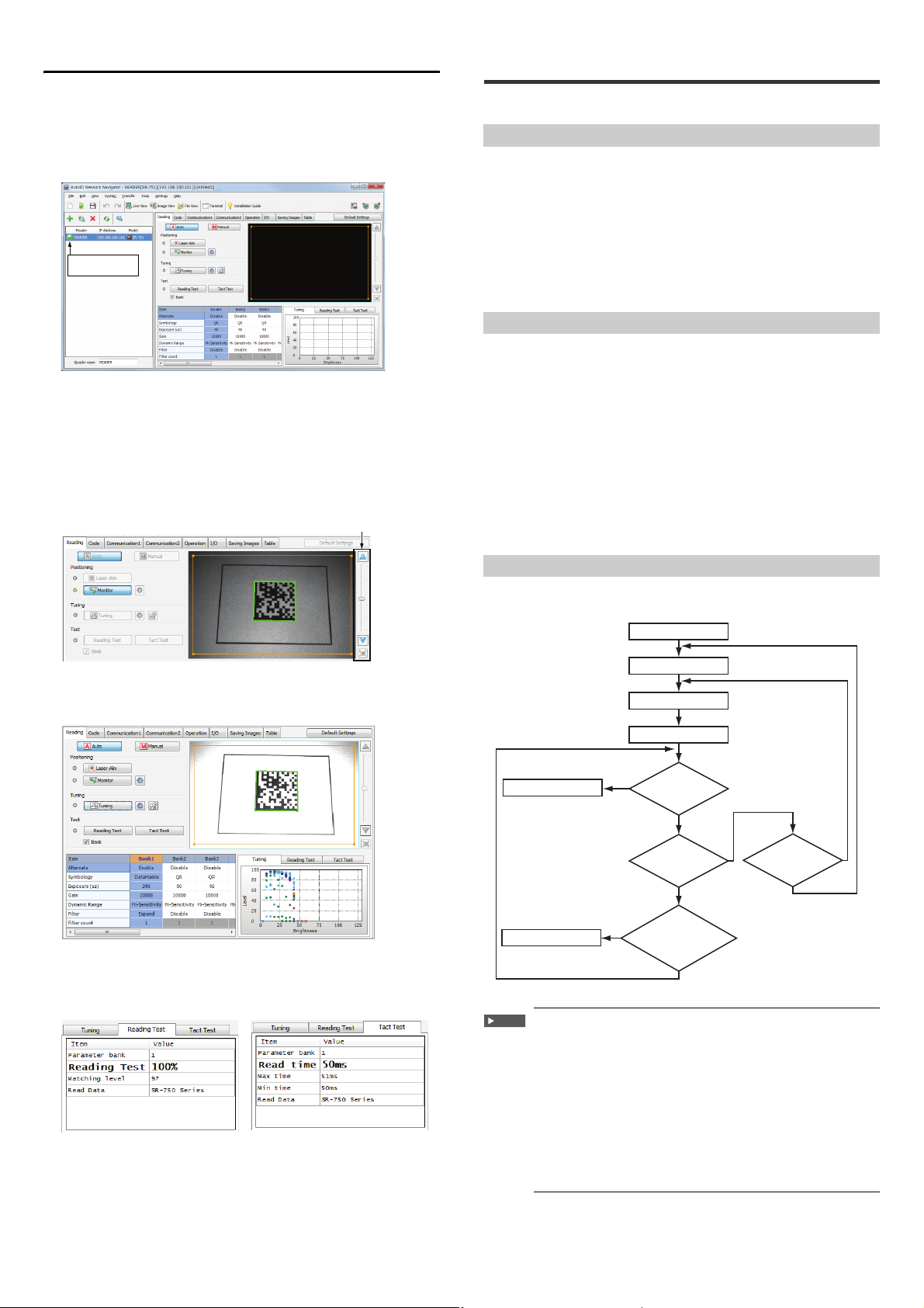
Activation using AutoID Network Navigator
Lights up in green
or blue
Brightness adjustment bar
YES
YES
YES
YES
NO
NO
NO
NO
Reading success
Start reading
Scanning
Decoding
Read error
Select parameter bank
Was re ading
successful?
Level trigger
turned off?
or
One-shot
timeout?
Decode timeout
period remains?
Retry possible?
Quick calibration is performed using AutoID Network Navigator.
Confirming the actual scanned image, you can operate calibration.
1 Connects the SR-750 Series to the AutoID Network Navigator
The following screen will appear when the SR-750 Series is detected.
Confirm that the indicator displayed on the left of the reader name lights up in
green or blue.
2 Click the [Pointer] button.
The laser pointer of the SR-750 Series lights up. Adjust the center of the code
to the position where the laser pointer emitted.
3 Click the [Monitor] button.
Looking at real-time scanned images, you can confirm the code positions.
Adjust the brightness using the "Brightness adjustment bar" on the right.
After the code position is determined, press the "Monitor" button to finish the
setting.
3-3 Alternate Function
This section describes the alternate function.
Alternate Function
The SR-750 Series can perform the reading operation while switching between
multiple parameter banks that are registered for the code being read.
The function that performs reading operation with the most appropriate parameter
while automatically switching the parameter bank - this is called "Alternate
Function".
Even when there are fluctuations in printing conditions or reading distance, since it
operates by switching between multiple parameter banks during a single read
operation, a stable read operation is provided.
By default, read operation is performed using the parameter bank 0 (bank for read
quick setup code).
Parameter banks
The SR-750 Series sets parameters necessary for code recognition such as scan
conditions and filter conditions.
Location where this setting is stored is called a "Parameter Bank".
The SR-750 Series has 10 parameter banks. Multiple optimal parameters can be
registered according to work conditions and printing conditions.
The following settings are stored in the parameter bank.
• Code type............................Set the version of the code to be read, the number of
codes, and the output length limitation function.
• Internal light/External light... Set whether or not to use internal lighting and
external lighting.
• Scan conditions................... Set exposure time, gain, and dynamic range.
• Filter .................................... Set the filter condition to be used.
• Others ................................. Set the alternate, decoding area, algorithm, etc.
4 Click [Calibration] button.
The most appropriate scan condition is automatically set according to the code.
Settings are registered with bank, and the operation finishes.
5 Perform the reading test.
Perform the reading rate test and processing time test, and confirm the reading
stability of the calibration result.
• Reading rate test display screen • Processing time test display screen
Alternate Function Operations
The following flow chart illustrates operations that occur during the alternate
function:
* Reading starts from the bank set as the "Alternate start bank".
Important
Since the alternate function cycles through the parameter banks
one at a to determine the optimal settings, overall processing time
may increase. (The processing time depends on the decode
timeout period setting.)
The alternate function is turned off by default. The function is
enabled automatically after the Tuning operation has been
performed on any of the parameter banks.
The alternate function is disabled in the following cases:
• When using the read mode in the burst mode
• When the alternate function is turned off for all parameter banks
• When the bank specify trigger input command (LON01 to 10) is
sent to directly specify the parameter bank for reading.
11
E SR-750 UM
Page 12
Bank prioritizing function
Point
Reference
Reading
order
Parameter bank
No.
Reading
order
Parameter bank
No.
1
1
1
3
2
2
2
1
3
3
3
2
4
4
4
4
Reading
Success
Activate the test. Stop the test.
Tes t in g
Test operations
Tes tin g
Test commands
Timing operation
Testing
Tes t i ng
Activate the test. Stop the test.
Timin g ON Timing OFF
When the alternate setting order is set to "Begin with successful bank", the next
reading starts from the parameter bank of the most recent successful reading.
When codes with similar conditions are read in sequence, prioritizing according to
the last successful bank may result in a shorter reading processing time.
Operation of the bank prioritizing function when parameter banks 1 to 4 are
used
The reading order is changed to start reading from the parameter bank of the
previous successful reading.
The bank prioritizing function is effective only in Operation mode.
The reading order is reset to the default setting when one of the
following operations is performed:
• Stopping the power supply
• Entering the test mode
• Entering Setting mode or Test mode
• Changing the alternate setting
Online mode
Online mode is useful for troubleshooting issues during run-time operation.
Online test mode can only be enabled through serial command input.
"8-2 Operation Commands (Page 71)"
To begin the test, turn the timing input on. To end the test and output results, turn
the timing input off.
Test Mode Measurement Status
The measurement status of the test mode can be checked on the multiple LED
indicator.
The multiple LED displays the following symbols during test mode.
Multiple LED status
5 bars lit
4 bars lit
Reading rate
(%)
90 to 100 Up to 99 LEVEL5 Green
70 to 80 100 to 199 LEVEL4 Green
Processing
time (ms)
Code position
measurement
OK/NG/
ERROR LED
3-4 Test Mode
This section describes the test mode of the SR-750 Series.
SR-750 Series Test Mode
Function Description
Reading rate test mode Offline Scans codes 10 times and measures the
Offline This test mode checks the number of
Read time test mode Offline This test mode measures the amount of
Offline This test mode measures the amount of time
Code position measurement
test mode
Offline In this test mode, the level that indicates how
For more information about the TEST button operations of the SR-750 Series or
the multiple LED status display, refer to "3-1 Using the SR-750 Series (Page
9)".
•
It is also possible to perform the test mode by specifying a parameter
bank.
"8-2 Operation Commands (Page 71)"
• If no parameter banks have setting values, the test mode is
performed for the parameter bank 0 (bank for read quick setup
code).
reading rate according to the number of times
that the code was read correctly.
successful decodes against the number of
decodes attempted while the trigger input is
turned ON.
decode time that it takes to read a code and
outputs the result every 10 decodings are
performed.
that it takes to read a code and outputs the
result when the trigger input turns OFF.
far the code shifts from the center of the field of
view is measured.
3 bars lit
50 to 60 200 to 299 LEVEL3 Green
2 bars lit
30 to 40 300 to 399 LEVEL2 Green
1 bar lit
10 to 20 400 or more LEVEL1 Green
0 bars lit
Reading error Red
Test Mode Details
This section describes the advanced details of each test mode.
Reading rate test mode
This test mode scans codes and measures the number of successful reads.
The offline mode scans 10 times and outputs the number of successful reads.
The offline test mode outputs the reading rate which is obtained from the number of
decodes against the number of decodes attempted while the trigger input is ON.
The parameter bank switches while scanning, just as when reading with the
alternate function. When reading is successful, the parameter bank used for
reading is fixed and the reading rate is calculated.
When a read error occurs, the test mode switches to another parameter bank and
continues the measurement.
Online and offline modes
Offline mode
Offline mode is useful for fine-tuning the installation position, distance or angle
during initial setup.
Data is continuously output as long as the test is active.
The test result data is output in real time.
E SR-750 UM
12
Page 13

Starting reading rate test mode
Reference
a = Pa rameter bank numbers
(01 to 10)
b = Rea ding rate
(1 to 100)
d = Average b rightness value in co de
region
(0 to 255)
a = Pa rameter bank numbers
(01 to 10)
b = Rea ding rate
(1 to 100)
c = Number of decoding successes/
Number of decoding operations
d = Average b rightness value in co de
region
(0 to 255)
a = Parameter bank No.
(00 to 10)
b = Lat est reading time
c = Maximum read time
(Maximum value of the read
operation from starting the read
time test mode to outputting data)
d = Mi nimum read time
(Maximum value of the read
operation from starting the read
time test mode to outputting data)
* The values for b, c, and d will be
zero suppressed.
a = Parameter bank No.
(00 to 10)
b = Po sition level (0 to 5)
The following procedures can be used to start and stop the reading rate test mode:
• Start: Hold the button for 2 seconds.
Stop: Tap the button once briefly.
• Start: Send the TEST1 (#TEST1) command from the control host.
Stop: Send the QUIT command (#QUIT) from the control host.
• Using AutoID Network Navigator or direct serial commands, assign "TEST" and
"Reading rate test mode" to one of the IN terminals.
Start: Turn the input on
Stop: Turn the input off
Reading rate test mode output data
Offline mode
The offline mode outputs data in the following format every 10 reading operations.
Read data
Online mode
The online mode outputs data in the following format when the trigger input is
turned off.
Read data
:a:b%:d
:a:b%:c:d
Read time test mode output data
Offline mode
The offline mode outputs data in the following format every 10 successful
decodings or every time the decoding fails.
Online mode
The online mode outputs data in the following format when the trigger input is
turned off.
(The format is the same for offline and online modes.)
Read data
Reference
: a : now = b ms : max = c ms : min = d ms
• When starting test mode, the data addition function is inactive.
• When TEST2nn (#TEST2nn) (nn: Parameter bank No.) is sent, the
read time test mode is run for the bank with the specified parameter
bank number.
• When the TEST2nn (#TEST2nn) command is sent or when there is
only 1 parameter bank for reading, the specified decode timeout
period is ignored and read operation is performed with a decode
timeout period of 2550 ms. If it has been determined that the image
cannot be decoded, measurement of the image is stopped without
waiting for the decode timeout period expiration.
Code position measurement test mode
• When starting test mode, the data addition function is inactive.
• When TEST1nn (#TEST1nn) (nn: Parameter bank No.) is sent, the
reading rate test mode is run for the bank with the specified
parameter bank number.
Read time test mode
This test mode measures the amount of time that it takes to read a code and
outputs the result.
The parameter bank switches while scanning, just as when reading with the
alternate function. If reading is successful, the amount of time required from the
start of reading until the completion of reading is measured and output. If the
decoding fails, the read time becomes 0 ms.
Starting read time test mode
The following procedures can be used to start and stop read time test mode:
• Start: Hold the button for 3 seconds.
Stop: Tap the button once briefly to finish.
• Start: Send the TEST2 (#TEST2) command from the control host.
Stop: Send the QUIT command (#QUIT) from the control host to finish.
• Assign "TEST" and "Reading rate test" to one of the IN terminals.
Start: Turn on the input
Stop: Turn off the input
This test mode measures how far the code shifts from the center of the field of
view.
This test mode can be used to perceive the amount of displacement and adjust
both the code position and the SR-750 Series installation location.
Ideal position (LEVEL5) Shifted position (LEVEL1)
The center of the code should coincide with
the center of the field of view.
The code is displaced from the center of the
field of view.
Starting code position measurement test mode
The following procedures can be used to start and stop code position
measurement mode:
• Start: Hold the button for 4 seconds.
Stop: Tap once briefly to finish.
• Start: Send the TEST3 command from the control host.
Stop: Send the QUIT command from the control host.
• Assign "TEST" and "Positioning Test" to one of the IN terminals.
Start: Turn the input on
Stop: Turn the input off
Code position measurement test mode output data
During code position measurement test mode, data of the average of 10 scans (the
fractional portion is dropped) is sent to the computer in the following format after
scanning 10 times:
Read data
:a: level = b
13
• When starting test mode, the data addition function is inactive.
Reference
• The code position measurement test mode does not run in online
mode.
• When TEST3nn (nn: Parameter bank No.) is sent, the code position
test mode is run for the bank with the specified parameter bank
number.
E SR-750 UM
Page 14
3-5 Preset/Verification
Reference
NOTICE
NOTICE
Data
A0 96 B···
First reading
Preset value
98
Preset value
+2
A0 98 B···
Reading + Verification
98
Verification
A0 96 B···
Reading + Verification
00
Verification
Numerical value
+ 2
"Verification
OK"
Numerical value
+ 2
A0 00 B···
Reading + Verification
00
Verification
"Verification
NG"
"Verification
OK"
Function
This section describes the preset/verification function.
Preset/Verification Function
This function allows the SR-750 Series to verify the read code data against the
registered code data (preset data), and output an OK/NG signal to indicate whether
or not they match. This allows the SR-750 Series to perform simple detection of
different codes without a sensor or other devices.
One set of preset data can be stored in the SR-750 Series (maximum 494 digits).
The starting digit (starting position) and range (number of digits) for the verification
can be set in the preset data, so even codes with more than 494 digits can be
verified.
* If the multi 2 read mode or multiple read mode is set, the preset verification
function cannot be used.
The verification starts at the specified starting position on the
preset data and continues for the specified number of digits. Data
cannot be verified at multiple points.
Registering preset data
Use one of the following procedures to register preset data with the SR-750 Series:
• Read a target code by turning on the external input terminal.
* You need to assign the preset data input function to the external input terminal
in advance.
"3-6 Multi-I/O Function (Page 14)"
• Set with the AutoID Network Navigator "5-4 Details of Settings View (Page
34)"
• Set with a setup command "8-3 Details of Configuration Commands (Page
75)"
Output data format for the preset registration result
The following output data format is used when the preset data is registered.
PR nn : Result data nn = Preset registration result (00 to 05)
Sequence Verification Function
This function allows verification of codes including numerical values which change
in series, such as workpiece serial numbers.
When the verification is OK, a value is added to/subtracted from the preset value.
When the verification is NG, neither addition nor subtraction is performed.
When the sequence verification is set, the first data read after the setup or poweron is used as the preset data, and the numerical data for the number of digits set is
verified.
When the PRESET input terminal is turned on during the automatic increment
verification, the current preset value is cleared, and the data to be loaded next is
used as the first load data.
The sequence verification requires the following settings:
• Verification method .........Select "Sequential".
• Starting digit ....................Set the number of digits where the value verification
starts.
• No. of digits ("Length") .... For the numerical verification, the acceptable number
of digits is 1 to 9 digits.
• Increment ........................Enter a value used to add to or subtract from the read
code value. (-9999 to 9999)
The following is the operation example when the starting digit is the third one, two
digits are referenced and an increment of +2 is specified:
The following restrictions are placed on the sequence verification
function:
• The verification results in NG when a value other than a
numerical value is read.
• The preset data cannot be registered through communication.
nn Description Result data
00 Preset registration success Read data
01 Preset read failure Read error data
02 The preset effective digit is specified as 0.
The number of digits of read data is less
03
than the number of digits for preset start.
The preset registration is not possible
04
because the operation mode is set to multi
2 or multiple read.
05 Two or more "!" exist in preset data.
[null]
Output terminal operation
The output terminals perform the following operation:
• Reading successful and matches preset data ............. OK is output
• Reading successful but does not match preset data ... NG is output
• Read error .................................................................... ERROR is output
• Preset data is registered successfully.......................... PRESET OK is output
By default, the PRESET OK output is not assigned to any of the
OUT1 to OUT3 terminals. To connect the PRESET OK output to an
NOTICE
external device, assign the PRESET OK output to an appropriate
OUT terminal.
Functions of "!" and "?" in the preset data (wild cards)
Registering "!" or "?" with the preset data increases the flexibility when comparing
and verifying the code data against the preset data.
"!" .......This character represents an unlimited number of digits and can be used
when any character for any number of digits is OK. If the preset data is "A B
C!", all codes that begin with "ABC" are verified as a match. If the preset
data is "!ABC", all codes that end with "ABC" are verified as a match. A
maximum of 1 "!" can be registered with the preset data.
"?" ......This character represents 1 digit and can be used when any one character
is OK. If the preset data is "A B??5 6", any 2 characters positioned in ?? are
verified as a match. If the preset data has not been registered, "!" is
registered instead. Consequently, OK is output when a barcode is read
successfully and ERROR is output when reading fails, regardless of the
data of the bar code.
By default, the PRESET output is not assigned to any of the OUT1 to
OUT4 terminals. To connect the PRESET OK output to an external
device, you need to assign the PRESET OK output to an appropriate
E SR-750 UM
OUT terminal.
3-6 Multi-I/O Function
You can assign various operating conditions to the I/O terminals of the SR-750
Series. This section describes operations available with the Multi-I/O function.
Function and Operation of the Input Terminals (IN1 and IN2)
Functions assigned to the input terminals
Only 1 of the following functions can be assigned to each of the input terminals IN1
and IN2:
• Trigger input: Use as the input terminal to start/stop reading codes.
• Preset data input: Use as the input terminal to register preset data.
• Start test mode: Use as an input terminal to activate the specified test mode.
(This function cannot be used to start the online test mode.)
• Clear PLC link error: Use as the terminal to clear the PLC link error.
• Tuning operation: Use the terminal to activate the quick calibration function.
• None: Select this option when the terminal is not used as an input terminal.
Use AutoID Network Navigator or setup command to change the setting or assign
the desired function.
* By default, the functions are assigned as follows:
IN1: Trigger input
IN2: Preset input
14
Page 15

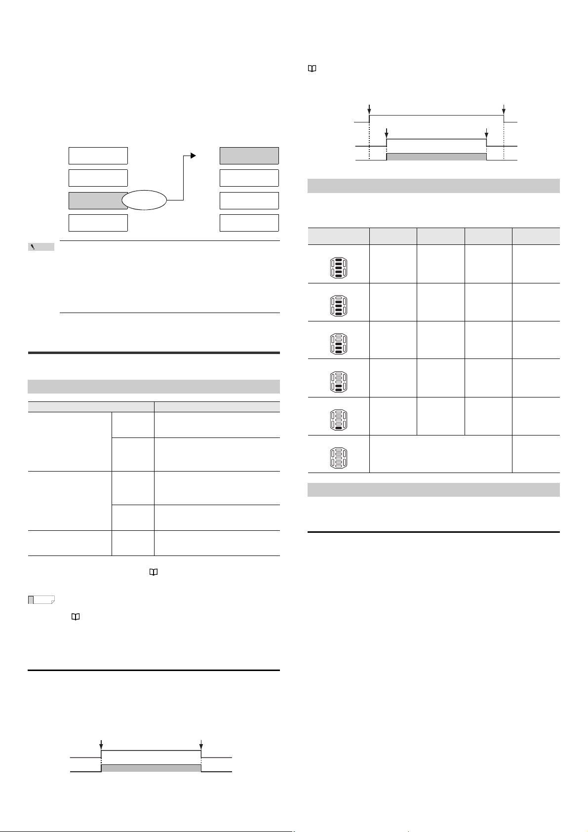
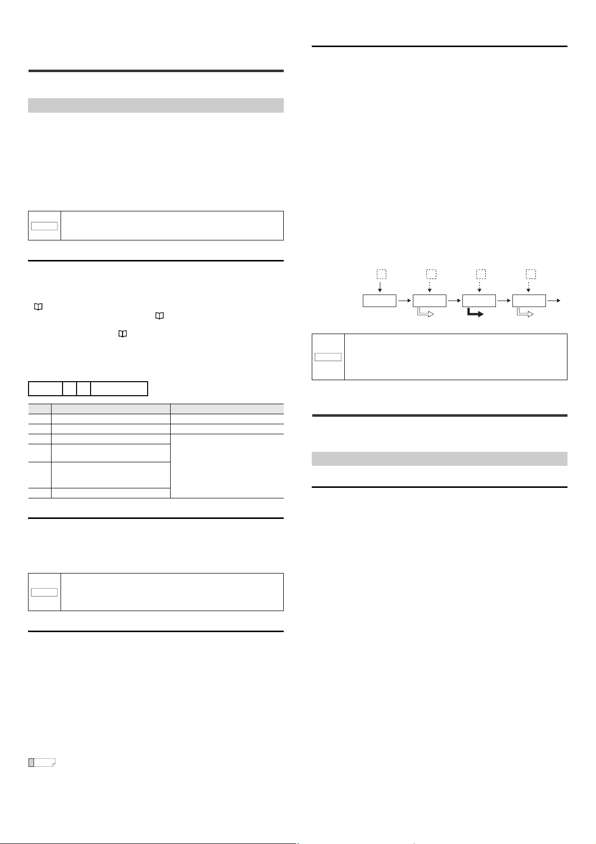
Input terminal status and operation
ON
Timing input
Reading operation
ON
Timing input
Reading operation
Timing input
Reading operation
NOTICE
ON
OK/NG/ERROR
STABLE/UNSTABLE
PRESET OK/TUNING OK
ON
Event occurrence
Period of time set for output ON time
The table below shows the relationship between the status of the input terminal
and the operation of the assigned function.
Function assigned to the
input terminal
Trigger input (TIMING) Start reading. Stop reading.
Preset input (PRESET) Start preset data registration. Finish preset data registration.
Start test mode. (TEST) Activate the test mode. Quit the test mode.
Stop PLC error Stop error ―
Tuning operation (TUNING) Start quick calibration Quit quick calibration
ON OFF
Synchronous IN LED
Users can set the SR-750 Series to illuminate its IN LED when the IN1 or IN2
terminal turns on. When both IN1 and IN2 terminals synchronize with the IN LED,
the LED illuminates based on the OR condition of the terminal status.
(By default, only the IN1 terminal synchronizes with the LED.)
Input polarity setting
The polarity of the input terminal can be selected from "N.O. (normally open)
contact" or "N.C. (normally closed) contact".
(By default, "N.O. contact" is selected.)
The same input polarity is set for IN1 and IN2.
Power-on trigger setting
Normally, the input terminal recognizes the change in the input signal (ON/OFF)
after the SR-750 Series is turned on and its operation stabilizes.
The input terminal does not operate if the input signal turns on before the operation
stabilizes (approximately 500 ms after power on).
If "Power-on trigger" is enabled, the SR-750 Series recognizes the input ON status
during the start-up period, and after the operation stabilizes, it performs the
operation specified for the input signal.
(By default, "Power-on trigger" is disabled.)
Operation of Norm. open and Norm. closed
Norm. open (Normally open)
•Normal
Norm. closed (Normally closed)
•Normal
Function and Operation of the Output Terminals (OUT1, OUT2 and OUT3)
Functions assigned to the output terminals
The following functions can be assigned to the output terminals (OUT1 to OUT3).
You can assign one or more functions to each output terminal.
Result output
This function outputs judgment results according to the SR-750 Series operation.
• OK .................... This signal is output when a bar code is read successfully or
when the comparison/verification against preset data matches.
• NG.................... This signal is output when the comparison/verification against
the preset data does not match.
• ERROR ............ This signal is output when a read error occurs.
• STABLE............ This signal is output when reading is stable ("Matching level
assessment function" or "Code quality verification function" is
enabled and the matching level or Code quality verification result
exceeds the set threshold).
• UNSTABLE ...... This signal is output when reading is unstable ("Matching level
assessment function" or "Code quality verification function" is
enabled and the matching level or Code quality verification result
falls below the set threshold).
• PRESET OK .... This signal is output when the preset data is registered
successfully.
• TUNING OK ..... This signal is output when the calibration is complete.
Operation output
This output function notifies that the SR-750 Series is currently running.
• TRG BUSY.......... During the start-up period, trigger input, preset data
registration, calibration, test mode, or while images are being
sent to FTP, bank numbers are being displayed, live view data
are being sent, monitoring is being performed, while the laser
pointer is on, images are being saved to ROM, the quick setup
codes are being read or being scripted
• LOCK BUSY ....... Forced trigger lock is being applied.
• MODE BUSY....... The quick setup code is being read, during test mode
• ERR BUSY.......... Error occurred (buffer full, setting save error)
External light control output
• EXT. LIGHT......... This signal is output to control external illumination.
• The result outputs (OK, NG, ERROR, STABLE, UNSTABLE,
PRESET OK, TUNING OK) and the outputs in operation (TRG
BUSY, LOCK BUSY, MODEBUSY, ERR BUSY) and EXT.LIGHT
cannot be set for the same terminal.
• EXT.LIGHT can be assigned to OUT3 only. Also, when
EXT.LIGHT is assigned to OUT3, no other output can be
assigned to OUT3.
• Power-on trigger setting
ON
Required input duration setting
Users can set the "Required input duration", which is the period required for the ON
status of the input terminal to be recognized. The function assigned to the input
terminal is activated after the input stays on for specified time or longer.
(Required input duration setting range: Selectable from 1 ms, 2 ms or 10 ms;
default setting is 1 ms.)
Output terminal operation
The output terminals operate differently depending on the assigned function. There
are three types of operations as shown below:
OK, NG, ERROR, STABLE, UNSTABLE, PRESET OK, and
TUNING OK output
The above signals turn on the output for the specified output ON time when the
respective event occurs.
* For the above output functions, a higher priority is assigned to the output of the
function which occurred last.
Consequently, when the next operation occurs during the output ON time of the
previous operation, the signal is switched to output the signal of the higher priority
function.
15
E SR-750 UM
Page 16
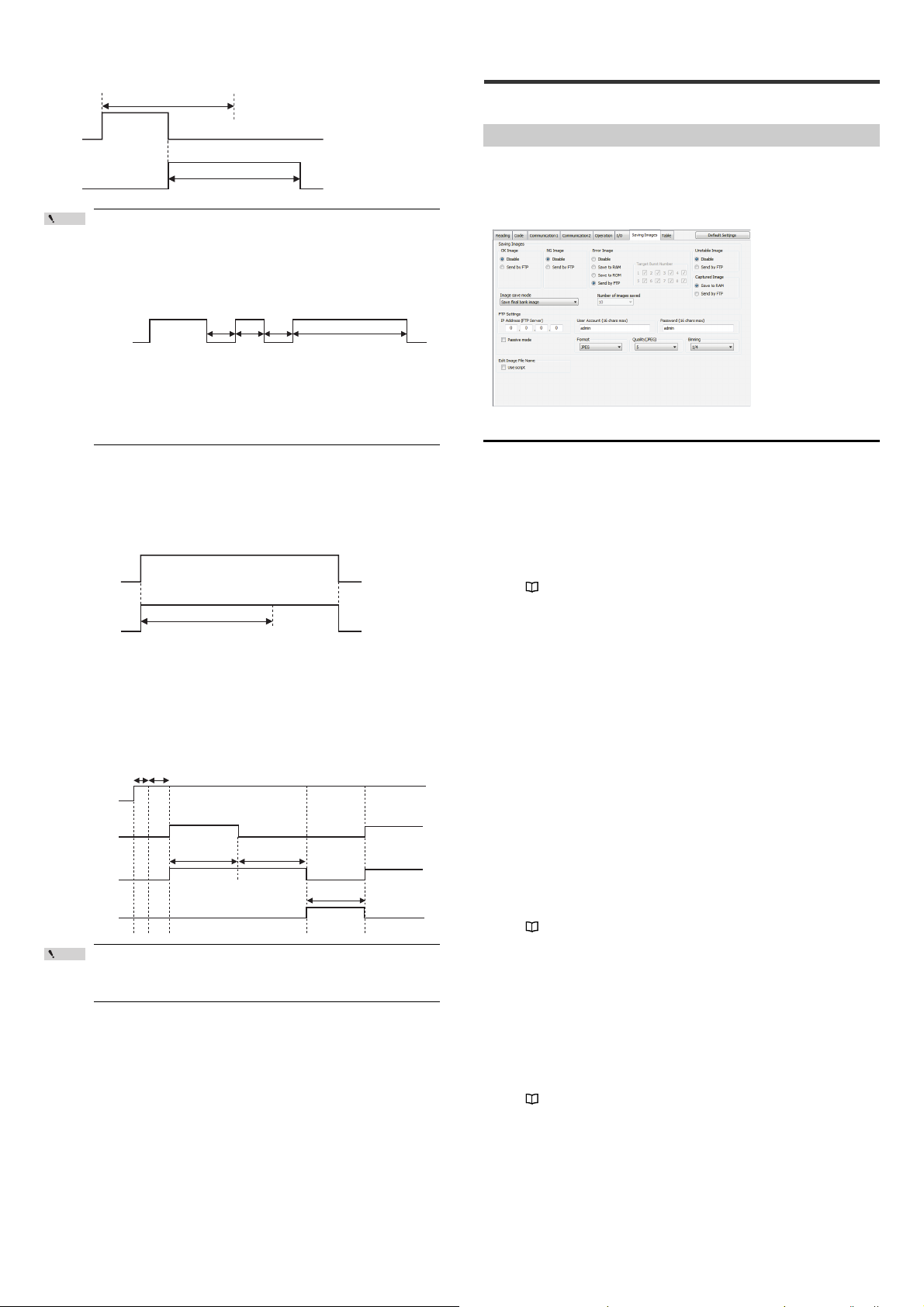
Timing diagram (When OUT1 outputs an OK signal and then OUT2
Point
Point
Period of time set for output ON time
Period of time set for output ON time
10 ms 10 ms 10 ms
OUT1
(OK)
ON
Period of time set for output ON time
TRG BUSY/
LOCK BUSY/
MODE BUSY/
ERR BUSY
ON
Period of time set for output ON time
Event occurrence
Event occurrence Event end
Trigger input
EXT.LIGHT output
Scanning
Decoding
Input pulse width Scan delay time
0.09 to 9.99 ms Approx. 16 ms
Exposure time
Image capture time
Decode timeout
period
Decoding process
not performed
outputs a NG signal)
ON
OUT1
(OK)
ON
OUT2
(NG)
If the same operation occurs again within the period of the output
ON time, the output turns off for 10 ms and then turns on again to
output the signal of the next operation. (If the same operation
occurs continuously at short intervals, the output turns on for at
least 10 ms before it turns off and then turns on again.)
Timing diagram (When OUT1 outputs signals continuously)
Other than the example described above, the signal is switched
when any of the following events occurs:
• Change to Test mode/Read quick setup mode
• Laser pointer is turned on
•Error
•Buffer full
3-7 Image Saving Function
This section describes the image saving function of the SR-750 Series.
Image Saving Function
The image saving function is used to save the scan image into RAM/ROM of the
SR-750 Series based on the image saving mode settings or to send to PC via FTP
communication.
Saved images can be used for analyzing causes of read error, etc.
• AutoID Network Navigator setting screen
Type of images to be saved
TRG BUSY, LOCK BUSY, MODE BUSY and ERR BUSY
output
The above signals are retained until the corresponding event ends.
(The period is not affected by the period of time set for the output ON time.)
* If multiple BUSY outputs are assigned to one output terminal, the output signal is
turned off when all events finish.
EXT.LIGHT (external illumination) output
The above signal is output in synchronization with the scan timing.
The output polarity can be selected from "N.O. (normally open) contact" or "N.C.
(normally closed) contact".
The timing diagram shows the operation for the N.O. contact:
• EXT. LIGHT can be assigned to OUT3 only.
• When EXT. LIGHT is assigned to OUT3, no other output can be
assigned to OUT3.
Latest image
The SR-750 Series stores a scanned image to RAM temporarily and performs
decoding process for the image data.
The image before decoding process is called the "Latest image".
• The "Latest image" saves up to 10 images to RAM in one time reading operation.
• The type of image of the "Latest image" is set to "L" for the file name.
• To confirm the "Latest image", use the image view function and file view function
of the AutoID Network Navigator.
Refer to "5-10 ImageView (Page 52)""5-11 FileView (Page 53)"
Judged image
An Image for which decoding process is performed and the read result is judged is
called "Judged image".
The "Judged image" can be set for each judged result.
• Read OK, Verification NG, Unstable image
: Not save or FTP transmission
• Read error : Not save, RAM save, ROM save or FTP
transmission
The "Judged image" is saved according to the following rules.
•
The number of judged images to be saved varies according to the reading operation
and image saving mode. (Max. 10)
•
The type of image for the file name of the "Judged image" is set as follows
according to the judged result.
Reading success : S
Reading error : E
Verification NG : N
Unstable image : W
: X....... The image was scanned in the burst read mode,
but the decoding process was not performed.
• To confirm the "Judged image" saved into RAM/ROM, use the image view
function and file view function of the AutoID Network Navigator.
Refer to "5-10 ImageView (Page 52)""5-11 FileView (Page 53)"
Capture image
This is an image scanned using the capture function of the SR-750 Series. One
image is saved with one-time capture operation.
You can select either RAM or FTP transmission as the save destination for capture
images.
• Capture operation can be performed using the image view function or operation
command.
• The type of image is set to "C" for the file name of the "Capture image".
• To confirm the "Capture image" saved into RAM, use the image view function and
file view function of the AutoID Network Navigator.
Refer to "5-10 ImageView (Page 52)""5-11 FileView (Page 53)"
E SR-750 UM
16
Page 17
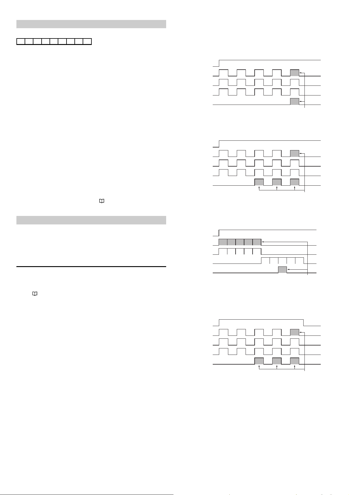
Image file name
Trigger input
Latest image
Reading
Success/Failed
Parameter bank
Bank
1
Images to be saved
Judged image
Bank2Bank3Bank1Bank
2
Failed Failed Failed Failed
Success
Bank
2
Trigger input
Latest image
Reading
Success/Failed
Parameter bank
Bank
1
Images to be saved
Judged image
Bank2Bank3Bank1Bank
2
Failed Failed
Success Success Success
Bank
2
Bank3Bank
1
Trigger input
Latest image
Reading
Success/Failed
Parameter bank
Scanning
1
Images to be saved
Judged image
Bank
1
Scanning 1
Failed
Bank
1
Scanning
5
Scanning2Scanning3Scanning
4
Bank
1
Bank
1
Bank
1
Bank
1
Scanning 5
-
Scanning 4
-
Scanning 3
Success
Scanning 2
Failed
Trigger input
Latest image
Reading
Success/Failed
Parameter bank
Bank
1
Images to be saved
Judged image
Bank2Bank3Bank1Bank
2
Failed Failed Failed Failed Failed
Bank
2
Bank3Bank
1
An image file name is set in the following format.
(1) _ (2) _ (3) _ (4) . (5)
(1) Image count value (3 bytes) IMG : When saved in ROM/RAM
000 to 999 : When sent via FTP
• The number is counted from 000
at startup.
• The counter value is
incremented each time one
image is sent.
• When the counter value of 999 is
incremented, the value returns to
000.
(2) Image type (1 byte) S : OK image
L : Latest
E : Error image
W : Unstable image
N : Comparison NG
C : Captured image
X : No decoding process
(3) Operation number (2 bytes) 00 : Latest
01 to 10 : From timing ON/OFF to specified
number
#1 to #8 : Burst number
(4) Bank number (2 bytes) 01 to 10
(5) Image file extension ROM/RAM : bmp
FTP : bmp or jpg
When the edit image file name function is enabled
When sending images via FTP transmission with [Edit image file name] – [Use
script] set to Enable, image file names can be freely changed.
For the edit image file name function, refer to "3-13 Edit data function/Edit
image file name function (Page 24)".
Image save mode
The following 3 image save modes are available:
• Save final bank image
• Save images after timing input ON
• Save images of the specified number before trigger input OFF
This section describes each mode.
Read OK/Comparison NG (When the preset/comparison
function is used)/Unstable image
(1) When the reading mode is the single read mode or multi 1 read mode
Only successfully read images of both the latest images and judged images are
saved.
(This is the example of when the parameter banks 1 to 3 are used.)
(2) When the reading mode is the multi 2 read mode
Judged images and parameter bank images successfully read are all saved.
For the latest images, only the image obtained last is saved.
(This is the example of when the parameter banks 1 to 3 are used.)
(3) When the reading mode is the burst read mode
For the latest images, all burst scanned images are saved.
For the judged images, only the images that can be decoded are saved.
(This is the example of when the burst execution bank is 1 and the number of
burst scans is 5.)
Save the latest bank image
In this mode, the SR-750 Series performs reading operation and saves the image
at the timing when the read result is judged.
Depending on the reading mode of the SR-750 Series, saved images and the
determination timing for images to be saved are as follows.
Refer to "4-4 Read Mode (Page 28)"
Read error
(1) When the reading mode is the single read mode or multi 1 read mode
When a reading error occurs, all parameter bank images used for reading
operation are saved one by one as judged images.
For the latest images, only the image obtained last is saved.
17
E SR-750 UM
Page 18
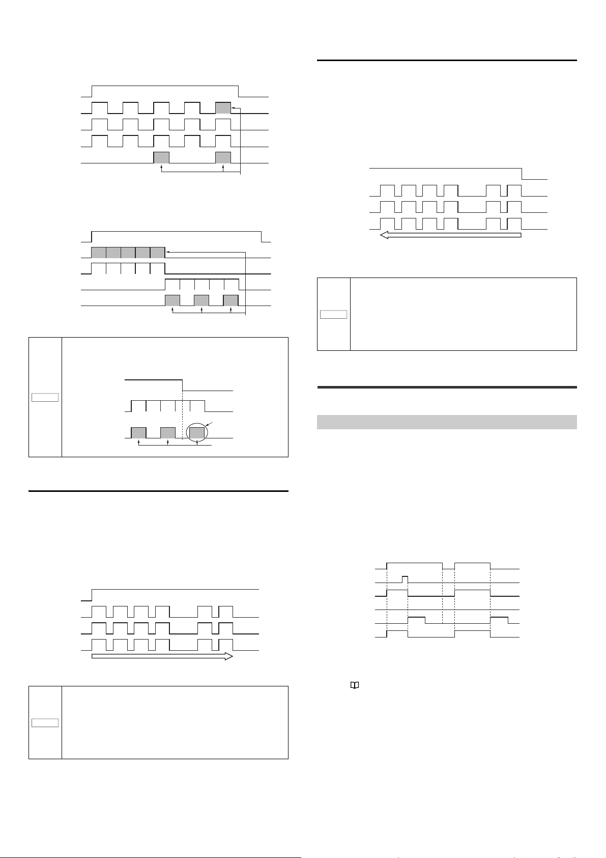
(2) When the reading mode is the multi 2 read mode
Trigger input
Latest image
Reading
Success/Failed
Parameter bank
Bank
1
Images to be saved
Judged image
Bank2Bank3Bank1Bank
2
Failed Failed Failed
Success
Failed
Bank
2
Bank
3
Trigger input
Latest image
Reading
Success/Failed
Parameter bank
Scanning
1
Images to be saved
Judged image
Bank
1
Scanning 1
Failed
Save
target
Scanning
5
Scanning2Scanning3Scanning
4
Bank
1
Bank
1
Bank
1
Bank
1
Scanning 5
Failed
Scanning 4
Failed
Scanning 3
Failed
Scanning 2
Failed
Save
target
Save
target
Trigger input
Reading
Success/Failed
Judged image
Images to be saved
Scanning 1
Failed
Save
target
Scanning 5
Failed
Scanning 4
Failed
Scanning 3
Failed
Scanning 2
Failed
Save
target
Save
target
The type of image is "X"
because decoding process
is not performed.
Trigger input
Latest image
Judged image
Parameter bank
Latest
1
Bank
1
Latest
n-1
Latest2Latest3Latest
4
Bank
3
Bank
1
Bank
3
Bank
2
The SR-750 Series saves images of the s pecified number (n) after the trigger input
turns ON.
Latest
n
Bank
1
Judged
1
Judged
n-1
Judged
4
Judged
3
Judged
2
Judged
n
NOTICE
Trigger input
Latest image
Judged image
Parameter bank
Latest
1
Bank
1
Latest
n-1
Latest2Latest3Latest
4
Bank
3
Bank
1
Bank
3
Bank
2
The SR-750 Series saves images of the specified n umber going back from the
image with the read result judged or the image when t he trigger input turns OFF.
Latest
n
Bank
1
Judged
1
Judged
n-1
Judged
4
Judged
3
Judged
2
Judged
n
Trigger input
Code
Data communication
Scanning + decoding
OK/NG/ERROR output
OK/NG ERROR
(When reading is successful) (When re ading failed)
TRG BUSY output
In the multi 2 read mode, if reading judgments (Success or Failed) differ among
parameter banks, the judged images of parameter banks that were judged as
reading error are saved.
For the latest images, the image obtained last is saved.
Save images of the specified number before trigger
input OFF
When the read result is judged or the trigger input turns OFF, the SR-750 Series
saves images of the specified number before then.
Image saving timing
The timing when images to be saved are determined is the same as the timing
when Read OK/Verification NG is determined, or the trigger input turns OFF and
Read error is determined.
The number of images to be saved can be specified by using AutoID Network
Navigator or setting commands for both the latest images and judged images.
(Max. 10 for each)
(3) When the reading mode is the burst read mode
If a read error occurs in the burst read mode, the judged images for the save
target burst numbers are only saved.
For the latest images, all burst scanned images are saved.
If the trigger input turns off before the decoding process for
scanned images are not complete, the judged images as save
targets are saved with the type of image "X" (Decoding process
not performed).
NOTICE
Save images of the specified number after trigger input
ON
When the read result is judged, the SR-750 Series saves images of the specified
number after the reading operation began.
Image saving timing
The timing when images to be saved are determined is the same as the timing
when Read OK/Verification NG/Read error is judged.
The number of images to be saved can be specified by using AutoID Network
Navigator or setting commands for both the latest images and judged images.
(Max. 10 for each)
·····
·····
·····
• Image number is counted in the obtained order as 1, 2, 3···.
• When the reading mode is the multi 1 read mode, image saving
is impossible with this operation.
• When the reading result can be judged before reaching the
specified number, the images until that point are saved.
• When the reading mode is the burst read mode, up to 8 images
are saved. In the burst read mode, the SR-750 Series saves
images of the specified number (burst scan count) for both the
latest images and judged images.
3-8 Silent Mode
This section describes the silent mode of the SR-750 Series.
Silent mode
A typical code reader outputs data of the result when the code is read or the read
error code when it is not read.
The SR-750 Series can be configured to restrain data communication and not to
output the result data to the host computer.
This function is called "Silent mode".
For example, if the application only uses the OK, NG or Read Error terminal
outputs, this information can be suppressed.
By configuring the SR-750 Series not to send all data, it eliminates the time
required for data transmission to/from the host computer. As a result, overall
reading time can be reduced.
Timing diagram (when OK/NG/ERROR data is restrained)
NOTICE
E SR-750 UM
·····
·····
·····
• When the reading mode is the multi 1 read mode, image saving
is impossible with this operation.
• When the reading result can be judged before reaching the
specified number, the images until that point are saved.
• When the reading mode is the burst read mode, up to 8 images
are saved. In the burst read mode, the SR-750 Series saves
images of the specified number (burst scan count) for both the
latest images and judged images.
Only data is not sent as shown above, but the OUT output terminal performs
normal operation.
* Even with the silent mode set, images can be saved with the condition set using
the image save function.
Refer to "3-7 Image Saving Function (Page 16)"
18
Page 19
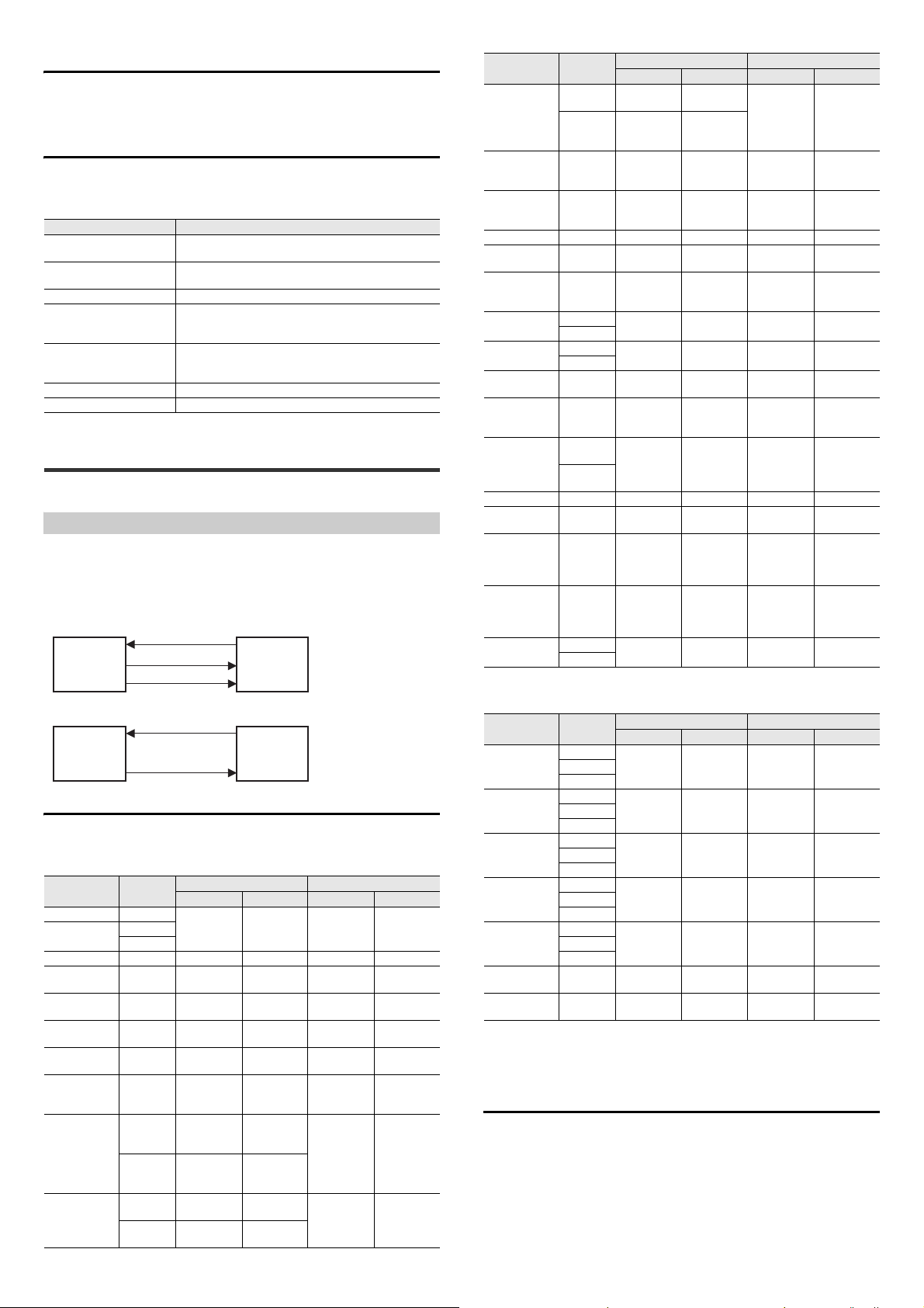
Silent mode setting procedure
The following 2 procedures for setting silent mode are available:
• Setting using the AutoID Network Navigator
• Setting with a command
Data subject to data communication restraint
By configuring the SR-750 Series, the following data communication can be restrained.
Setting items and setting details using the AutoID Network Navigator
Setting item Data subject to output restraint
Read (Comparison) OK
Comparison NG
Read ERROR Read error data
Stable Reading (OK/NG) Stable reading data
Unstable Reading (OK/NG) Unstable reading data
Preset Result Preset registration result data
Test Mode Measured data in test mode
3-9
SR-600 Compatible Output Mode
Read data
Read data judged as Comparison OK as a result of preset verification.
Preset Comparison NG data
Read data judged as Comparison NG as a result of preset verification.
Read data whose matching level or Code quality verification
result is judged as more than the threshold
Read data whose matching level or Code quality verification
result is judged as less than the threshold
This section describes the SR-600 compatible output mode of the SR-750 Series.
SR-600 compatible output mode
The SR-750 Series supports the Ethernet communication, so the operation command
format and response code format have been changed from the previous SR-600 Series.
When using the SR-750 Series in the SR-600 Series operation process or using
the control program for the SR-600 Series, setting the SR-600 compatible output
mode to Enable results in reduction in man-hours for program change.
• Standard mode
(1) LON
SR-750 PC or PLC
(2) OK, LON
(3) Read data
• SR-600 compatible output mode
(1) LON
SR-750 PC or PLC
(2) Read data
SR-600 compatible output mode functions
Commands and responses set to Enable in the SR-600 compatible output mode are as follows.
Operation commands
Command
name
Trigger input ON LON
Trigger input ON
(Bank settings)
Trigger input OFF
Start preset data
registration
End preset data
registration
Start reading the
quick setup code
End reading the
quick setup code
Check the quick
setup code
reading status
Check the input
terminal status
Output terminal
ON control
(individual
control)
Command
LONbb
LON, bb
LOFF OK, LOFF ER, LOFF, ee (N/A) (N/A)
PRON OK, PRON
PROFF OK, PROFF
RCON OK, RCON
RCOFF OK, RCOFF
RCCHK
INCHK, m
INmCHK
OUTON, m OK, OUTON
OUTmON OK, OUTmON
SR-750 Series normal output
Response Error code Response Error code
OK, LON ER, LON, ee (N/A) (N/A)
ER, PRON,
ER, PROFF,
ER, RCON,
ER, RCOFF,
OK, RCCHK,
Obtained
value
OK, INCHK,
Obtained
value
OK, INmCHK,
Obtained
value
ER, RCCHK, eeObtained
ER, INCHK,
ER, INmCHK,
ER, OUTON,
ER,
OUTmON, ee
SR-600 Compatible output
ee
ee
ee
ee
ee
ee
ee
Obtained
Obtained
(N/A) (N/A)
(N/A) (N/A)
OK ERRee
OK ERRee
value
value
value
ERRee
ERRee
ERRee
Command
name
Output terminal
OFF control
(individual
control)
Output terminal
ON control
(batch control)
Output terminal
OFF control
(batch control)
Soft reset RESET OK, RESET (N/A) OK (N/A)
Clearing the
send buffer
Check reading
history
Capture
Start tuning
Cancel tuning TQUIT OK, TQUIT
Obtain the
alternate order
Initialize the
parameter bank
Save setting SAVE OK, SAVE ER, SAVE, ee OK ERRee
Initialize the
settings
Obtain the
command status
Obtain the error
status
Erase error
images
Command
OUTOFF, m OK, OUTOFF
OUTmOFF
ALLON OK, ALLON
ALLOFF OK, ALLOFF
SHOTbb
SHOT, bb
TUNE, bb
TUNEbb
BANKORDER
BANKCLR,
BANKCLRb
CMDSTAT
ERRSTAT
ICLR, bb
ICLRbb
SR-750 Series normal output
Response Error code Response Error code
OUTmOFF
BCLR OK, BCLR (N/A) OK (N/A)
NUM
DFLT OK, DFLT ER, DFLT, ee OK ERRee
OK, NUM,
Obtained
value
OK, SHOT,
File name
OK, TUNE ER, TUNE, ee OK ERRee
BANKORDER,
Obtained value
bb
BANKCLR
b
CMDSTAT,
Obtained
value
ERRSTAT,
Obtained
value
OK, ICLR ER, ICLR, ee OK ERRee
ER, OUTOFF,
OK,
OK,
OK,
OK,
OK,
ER,
OUTmOFF,
ER, ALLON,
ER, ALLOFF,
ER, NUM, ee
ER, SHOT, ee OK ERRee
ER, TQUIT,
ER,
BANKORDER,
ER,
BANKCLR, ee
(N/A)
(N/A)
SR-600 Compatible output
ee
ee
ee
ee
ee
ee
Obtained
value
Obtained
value
Obtained
value
Obtained
value
Obtained
value
ERRee
OK ERRee
OK ERRee
ERRee
OK ERRee
ERRee
OK ERRee
(N/A)
(N/A)
Test mode commands
Command
name
Start reading
rate test mode
(offline)
Start reading
rate test mode
(online)
Start processing
time test mode
(offline)
Start processing
time test mode
(online)
Start position
test mode
(offline)
End test mode
(offline)
End test mode
(online)
Command
TEST1
TEST1bb
#TEST1
#TEST1bb
TEST2
TEST2bb
#TEST2
#TEST2bb
#TEST3
#TEST3bb
SR-750 Series normal output
Response Error code Response Error code
OK, TEST1
OK, #TEST1
OK, TEST2
OK, #TEST2
OK, TEST3
QUIT OK, QUIT ER, QUIT, ee OK ERRee
#QUIT OK, #QUIT ER, #QUIT, ee OK ERRee
ER, TEST1,
ER, #TEST1,
ER, TEST2,
ER, #TEST2,
ER, TEST3,
* bb : Parameter bank No.
ee : Error code
m: Pin No.
Obtained value : Value obtained after command operation
SR-600 Compatible output
ee
ee
ee
ee
ee
OK ERReeTEST1, bb
OK ERRee#TEST1, bb
OK ERReeTEST2, bb
OK ERRee#TEST2, bb
OK ERRee#TEST3, bb
How to set the SR-600 Series compatible output mode
Change the setting according to the following methods to set the SR-600 Series
compatible output mode to Enable.
• Change the setting using AutoID Network Navigator.
On the AutoID Network Navigator, select [Table] tab - [Others] - [Trigger command
response] - [Specify response character], and then specify SR-600 compatible. (Page 48)
• Send the setting command to set
19
E SR-750 UM
Page 20
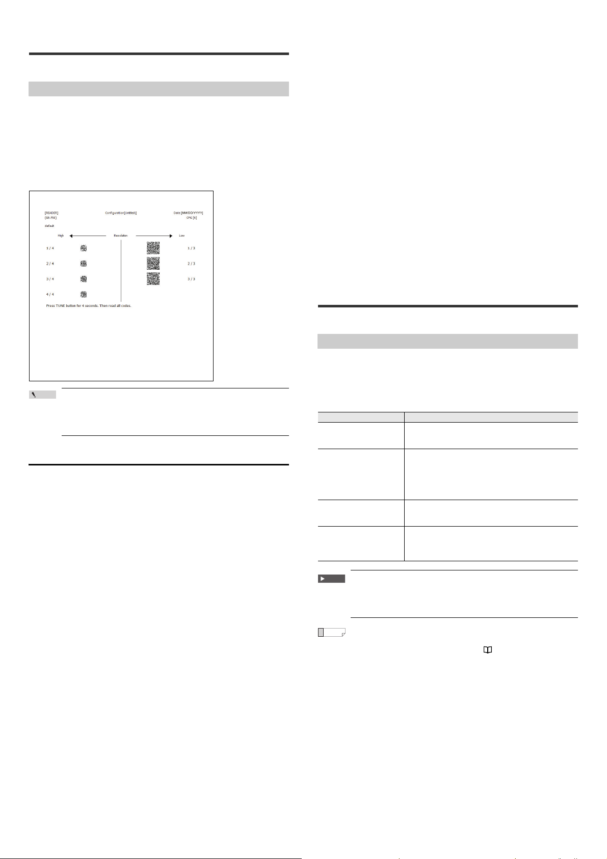
3-10
Point
This section describes the quick setup code.
Batch Setting Code
Quick Setup Code
Users can print the settings specified with AutoID Network Navigator as 2D code
and read the code with the SR-750 Series to change all the settings at once. When
printing the quick setup code, use the AutoID Network Navigator quick setup code
printing function.
Since the settings of the SR-750 Series can be changed by reading the quick setup
code, you can easily change the settings even in a location where a computer
cannot be used.
Print image
Sending the quick setup code reading commands
Send the quick setup code reading command (RCON) to read the quick setup
code.
1 Send the "RCON" command from the control device.
When the SR-750 Series receives the command normally, it returns "OK,
RCON", and "C" and "0" are displayed alternately on the multiple LED indicator
of the SR-750 main unit.
2 Read the quick setup code.
According to the code reading status, values displayed on the multiple LED
indicator of the SR-750 main unit change.
3 When all quick setup codes are read, "d" is displayed on the multiple
LED indicator of the SR-750 main unit.
4 Send the "RCOFF" command from the control device.
When the SR-750 Series receives the command normally, it returns "OK,
RCOFF", and the quick setup code reading operation finishes. (After the setting
is reflected, "d" on the multiple LED goes off.)
• While reading the quick setup code, the TRG BUSY and MODE BUSY
outputs turn ON.
• To cancel the quick setup code reading operation, send the "RCOFF"
command.
When reading the quick setup code with the high-resolution type
unit (SR-750HA), you must use a printer with high print quality.
When a printer with low print quality is used, the cells in the 2D
code may bleed and become unreadable.
How to read quick setup codes
Use one of the following methods to read the quick setup code
Reading the quick setup code using the TUNE button
1 Press and hold the TUNE button on the SR-750 Series for at least 4
seconds.
When the quick setup code reading operation starts, "C" and "O" are displayed
alternately on the multiple LED indicator of the SR-750 main unit.
2 Read the quick setup code.
According to the code reading status, values displayed on the multiple LED
indicator of the SR-750 main unit change.
3 When all quick setup codes are read, "d" is displayed on the multiple
LED indicator of the SR-750 main unit.
4 Press the TUNE button once briefly to finish the quick setup code
reading operation.
• While reading the quick setup code, the TRG BUSY and MODE BUSY
outputs turn ON.
• To cancel the quick setup code reading operation, press the TUNE button
once briefly.
When "F" is displayed on the multiple LED display, press the TUNE button
once briefly again.
3-11
Code quality verification function
This section describes the Code quality verification function.
Code quality verification function for the SR-750 Series
The Code quality verification function evaluates the level (High/Low) of total grade
based on the verification result output and the set threshold by verifying the 2D
code scanned with the SR-750 Series according to the marking quality evaluation
specified by a third-party institution.
The SR-750 Series provides the following 2D code verifications according to the
Code quality verification standards.
Standards Description
ISO/IEC15415
ISO/IEC TR 29158
(AIM DPM-1-2006)
SAE AS9132
SEMI T10-0701
Important
Note that this Code quality verification function is designed to
evaluate marking quality of the standards-compliant 2D codes of
the images scanned with the SR-750 Series, but cannot be used as
an official 2D code verification device.
Reference
When you select ISO/IEC15415, you can perform code quality
verification of standalone PDF 417 and Micro PDF codes. For
information on the verification items, see "Code Verification of
Japanese Pharmaceutical Drugs" in the "SR-750 Series Additional
Functions Manual."
This is the 2D code marking quality evaluation standard
established by International Organization for Standardization.
This is mainly used to evaluate 2D codes printed on labels.
This is the DPM (Direct Part Marking) 2D code marking quality
evaluation standard established by Automatic Identification
Manufacturers.
This is based on ISO/IEC15415.
This was also standardized by International Organization for
Standardization in 2011.
This is the DataMatrix code marking quality evaluation
standard established by SAE (Society of Automotive
Engineers) and used by the aerospace industry.
This is the DataMatrix code marking quality evaluation
standard established by SEMI (Semiconductor Equipment and
Materials International) and printed on semiconductor-related
materials.
E SR-750 UM
20
Page 21
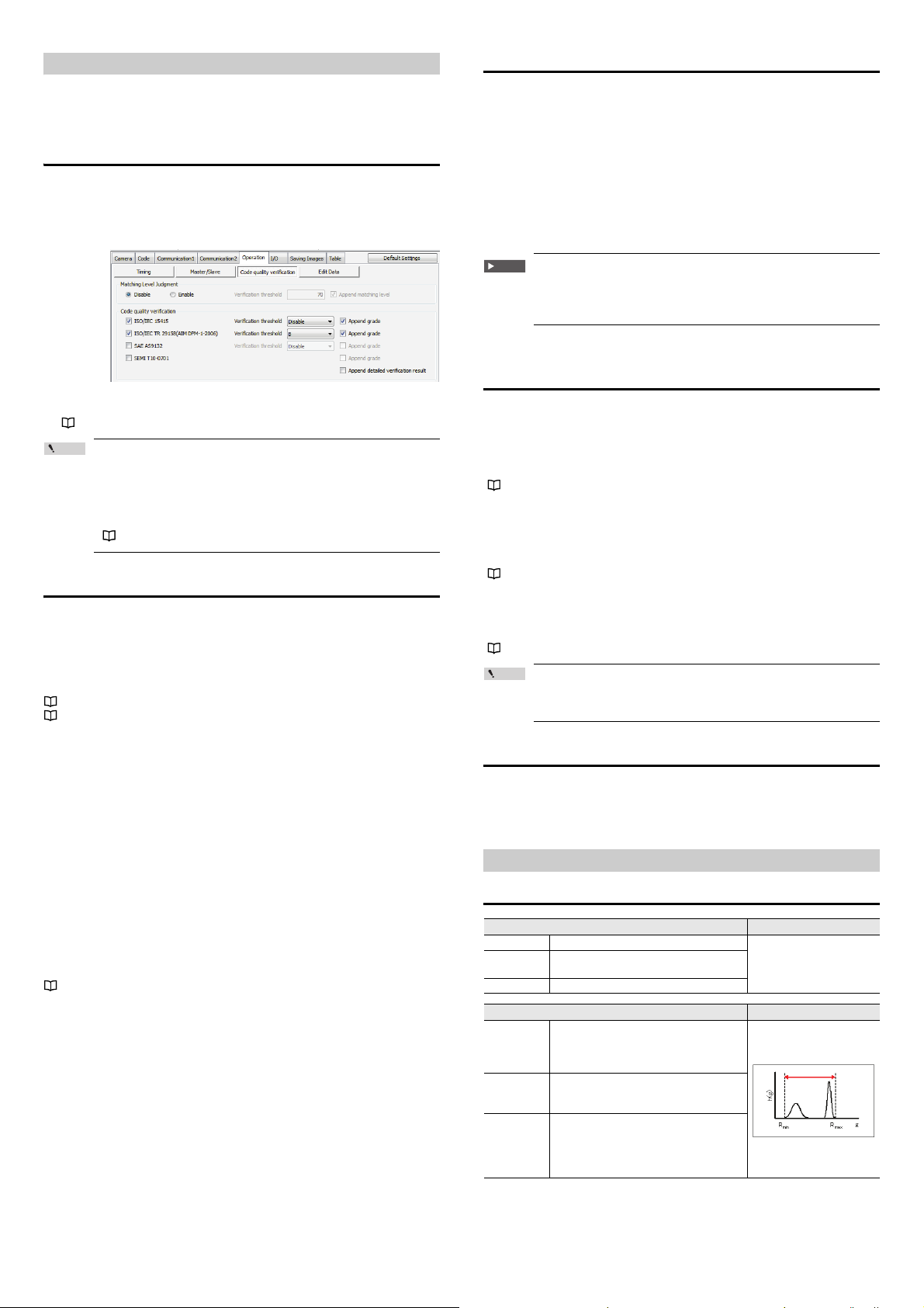
Code quality verification function settings
Point
This section describes the setting method of the Code quality verification function
and the setting items.
Setting method for the Code quality verification
function
To use the Code quality verification function, you need to enable the verification
settings you wish to use.
(1) Setting using the AutoID Network Navigator.
Press the "Code quality verification" button on the "Operation" tab in the
Settings view, and then check the desired verification standard.
(2) Setting using the setup commands
Send commands that enable the verification functions you wish to use.
"8-3 Details of Configuration Commands - Reading operation setting (Page 77)"
When the Code quality verification function is enabled, the decode
time becomes longer than when it is disabled.
Perform calibration after enabling the Code quality verification
function or set the decode timeout period required for reading.
Use the tact measurement test mode to confirm there is no
problem with reading time for operation.
( "3-4 Test Mode" (Page 12))
Append Code quality verification result data
To append the Code quality verification result data, the additional data setting and
data format setting are required.
Additional data setting
Select "Operation" - "Additional data" on the "Table" tab in the Settings view, and
then set verification results you wish to append as data to "Enable".
"5-4 Details of Settings View - [Table] tab (Page 43 or later)"
"3-11 Code quality verification function - Verification items description (Page 21
or later)"
Data format setting
Make the setting relating to the data format.
Set the following three items.
• Select expression of grades : Set the grade indication of the verification
result to either Alphabet or Numeric.
(ISO/IEC15415 and ISO/IEC TR 29158
(AIM DPM-1-2006) only)
• Append detailed verification result : Set whether to append verification items of
each standard to the total grade.
(ISO/IEC15415, ISO/IEC TR 29158 (AIM
DPM-1-2006) and SAE AS9132 only)
• Append values : Set whether to append evaluation values of
each verification item used for verification
result evaluation.
(ISO/IEC15415, ISO/IEC TR 29158 (AIM
DPM-1-2006) and SAE AS9132 only)
"7-2 Data Communication Format (Page 63)"
Code quality verification function Evaluation standard
Evaluation by the Code quality verification function is made for the total evaluation
grade.
Evaluation standards are as follows.
ISO/IEC15415, ISO/IEC TR 29158 (AIM DPM-1-2006)
High: Verification result >= Threshold value
Low: Verification result < Threshold value
SAE AS9132
High: Verification result = Pass
Low: Verification result = Fail
Important
SEMI T10-0701 does not offer total evaluation grade and cannot
make evaluations.
This means that functions that can be used after evaluation
cannot be used with SEMI T10-0701.
Functions that can use evaluation results of the Code
quality verification function
STABLE terminal output, UNSTABLE terminal output
STABLE terminal output......... This is output when the total evaluation grade is the
UNSTABLE terminal output ... This is output when the total evaluation grade is less
( "3-6 Multi-I/O Function (Page 14)")
threshold value or more.
than the threshold value.
Saving images of unstable reading
When the total evaluation grade is less than the threshold value, scanned images
are saved according to the setting (If the FTP transmission is set, images are sent
to the connection destination.).
( "3-7 Image Saving Function (Page 16)")
Silent mode
When the total evaluation grade is more or less than the threshold value, data
communication can be restrained using the silent mode.
( "3-8 Silent Mode (Page 18)")
Point
When multiple verifications are in process, these functions
operate in priority to the result which is less than the threshold
value.
Note when using the Code quality verification function
Code quality verification results may change according to the setting of the
parameter bank for scanning. If the color or contrast of the 2D code and
background change, consider preparing the parameter bank setting used as
standard and performing the Code quality verification using the setting.
Verification items description
ISO/IEC 15415
Decode success/failure DEC (Decode)
Description Evaluates whether decoding is possible or not.
Calculation
formula
Criterion ―
Symbol contrast SC (Symbol Contrast)
Evaluates the difference between the
Description
Calculation
formula
Criterion
maximum brightness value (Rmax) and
minimum brightness value (Rmin) in the code
area.
SC = (Rmax-Rmin)/255
Rmax : Maximum brightness value
Rmin : Minimum brightness value
A : more than 0.70
B : 0.55 to 0.70
C : 0.40 to 0.55
D : 0.20 to 0.40
F : less than 0.20
―
―
21
E SR-750 UM
Page 22
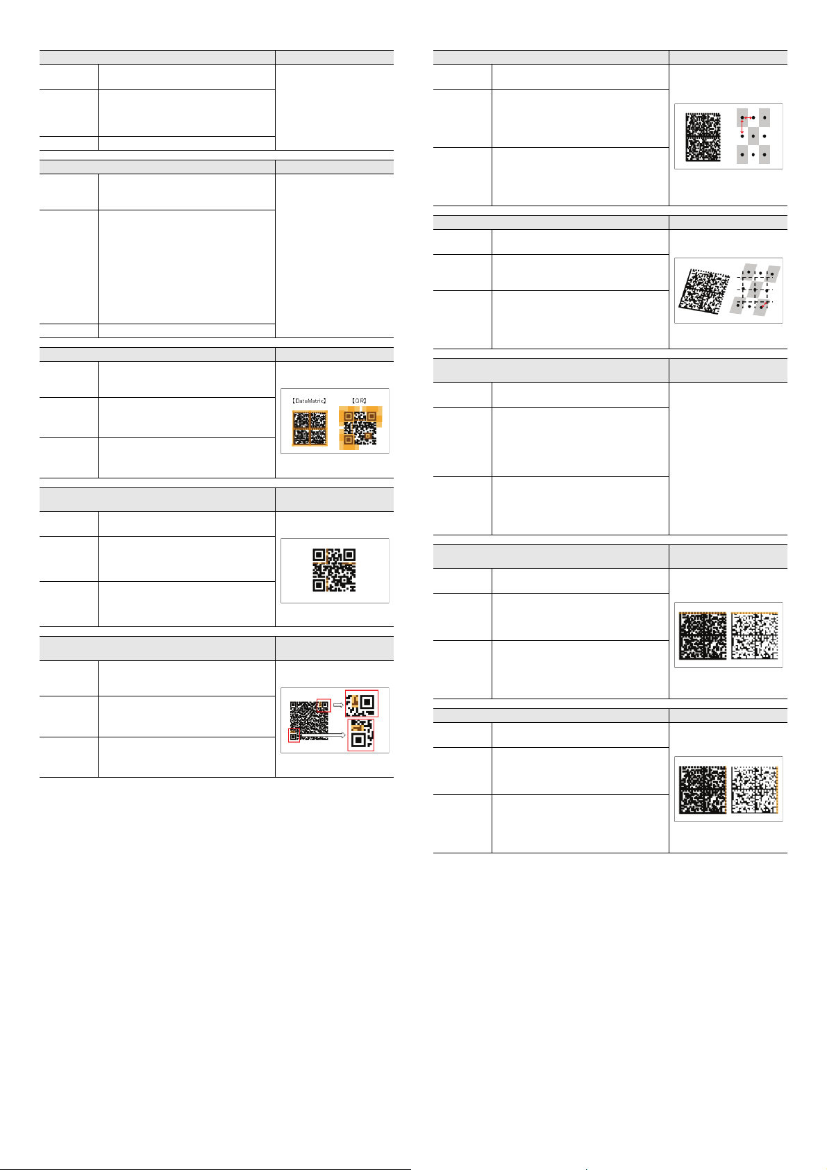
Modulation MOD (Modulation)
Description
Calculation
formula
Criterion ―
Description
Calculation
formula
Criterion ―
Description
Calculation
formula
Criterion ―
Description
Calculation
formula
Criterion ―
Description
Calculation
formula
Criterion ―
Evaluates the variation degree in cell
brightness
Each cell's MOD = 2 ½ (abs (R-GT)/SC)
R : Brightness value
GT : Binarization threshold value
SC : Symbol contrast
Reflectance margin RM (Reflectance Margin)
Evaluates the variation degree in cell
brightness with black and white of the correct
cell considered.
[White cell]
R >= GT → MARGIN = 2 ½ (R-GT)/SC
R < GT → MARGIN = 0
[Black cell]
R < GT → MARGIN = 2 ½ (GT-R)/SC
R >= → MARGIN = 0
MARGIN : Margin of each cell
R : Brightness value
GT : Binarization threshold value
SC : Symbol contrast
Fixed pattern damage FPD (Fixed Pattern Damage)
Evaluates the degree of the fixed pattern
damage (area on the right) dependent on the
code type.
Format information damage
Evaluates the format information damage
degree of QR code.
Version information damage
Evaluates the version information damage
degree of QR code (Model 2, version 2 and
later versions).
Axial nonuniformity AN (Axial Nonuniformity)
Description
―
―
―
(Format Information Damage)
―
(Version Information Damage)
―
FID
VID
Calculation
formula
Criterion
Description
Calculation
formula
Criterion
Description
Calculation
formula
Criterion
Description
Calculation
formula
Criterion
Description
Calculation
formula
Criterion
Evaluates the distortion degree in vertical and
horizontal size of the code.
AN = abs (Xavg = Yavg)/((Xavg = Yavg)/2)
Xavg : Average cell size in horizontal
direction
Yavg : Vertical cell size in horizontal
direction
A : less than 0.06
B : 0.06 to 0.08
C : 0.08 to 0.10
D : 0.10 to 0.12
F : more than 0.12
Grid nonuniformity GN (Grid Nonuniformity)
Evaluates the maximum position slip of each
cell
GN = Hmax/X
Hmax : Maximum position slip amount
X : Cell size
A : less than 0.38
B : 0.38 to 0.50
C : 0.50 to 0.63
D : 0.63 to 0.75
F : more than 0.75
Unused error correction
Evaluates the ratio of error correction unused
at the time of decoding.
UEC = 1.0 - ((e + 2t)/(d - p))
e : Number of code words that cannot be
read
t : Number of error code words
d : Number of error corrected code words
p : Number of error detected code words
A : more than 0.62
B : 0.50 to 0.62
C : 0.37 to 0.50
D : 0.25 to 0.37
F : less than 0.25
Print growth (horizontal)
Evaluates the mark cell growth in the
horizontal direction.
(D - 0.5)/0.15
D : On the horizontal clock pattern
Ratio of the number of pixels of mark
cell
A : -0.50 to 0.50
B : -0.70 to -0.50 or 0.50 to 0.70
C : -0.85 to -0.70 or 0.70 to 0.85
D : -1.00 to -0.85 or 0.85 to 1.00
F : less than -1.00 or more than 1.00
Print growth (vertical) PGV (Print Growth Vertical)
Evaluates the mark cell growth in the vertical
direction.
(D - 0.5)/0.15
D : On the vertical clock pattern
Ratio of the number of pixels of mark
cell
A : -0.50 to 0.50
B : -0.70 to -0.50 or 0.50 to 0.70
C : -0.85 to -0.70 or 0.70 to 0.85
D : -1.00 to -0.85 or 0.85 to 1.00
F : less than -1.00 or more than 1.00
(Unused Error Correction)
UEC
―
PGH
(Print Growth Horizontal)
E SR-750 UM
22
Page 23
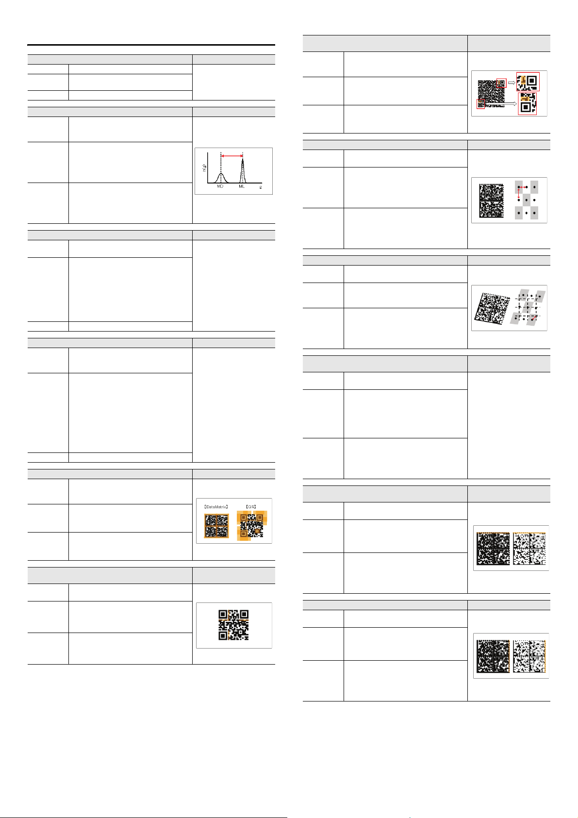
ISO/IEC TR 29158 (AIM DPM-1-2006)
Decode success/failure DEC (Decode)
Description Evaluates whether decoding is possible or not.
Calculation
formula
Criterion ―
Cell contrast CC (Cell Contrast)
Description
Calculation
formula
Criterion
Description
Calculation
formula
Criterion ―
Description
Calculation
formula
Criterion ―
Description
Calculation
formula
Criterion ―
Description
Calculation
formula
Criterion ―
Evaluates the difference between the average
brightness value of bright cell (ML) and
average brightness value of dark cell (MD).
CC = (ML - MD)/ML
ML : Average brightness value of bright
cell
MD : Average brightness value of dark
cell
A : more than 0.30
B : 0.25 to 0.30
C : 0.20 to 0.25
D : 0.15 to 0.20
F : less than 0.15
Cell modulation CM (Cell Modulation)
Evaluates the variation degree in cell
brightness
[White cell]
CM = (R - GT)/(ML - GT) (When R ≥ GT)
[Black cell]
CM = (GT- R)/(GT- MD) (When R < GT)
R : Brightness value
GT : Binarization threshold value
ML :
Average brightness value of bright cell
MD :
Average brightness value of dark cell
Reflectance margin RM (Reflectance Margin)
Evaluates the variation degree in cell
brightness with black and white of the correct
cell considered.
[White cell]
R >= MARGIN = (R-GT)/(ML-GT)
R < GT → MARGIN = 0
[Black cell]
R < GT→MARGIN = (GT-R)/(GT-MD)
R >= → MARGIN = 0
MARGIN : Margin of each cell
R : Brightness value
GT : Binarization threshold value
CC : Cell contrast
Fixed pattern damage FPD (Fixed Pattern Damage)
Evaluates the degree of the fixed pattern
damage (area on the right) dependent on the
code type.
Format information damage
Evaluates the format information damage
degree of QR code.
―
―
―
―
―
―
(Format Information Damage)
FID
Version information damage
Description
Calculation
formula
Criterion ―
Description
Calculation
formula
Criterion
Description
Calculation
formula
Criterion
Description
Calculation
formula
Criterion
Description
Calculation
formula
Criterion
Description
Calculation
formula
Criterion
Evaluates the version information damage
degree of QR code (Model 2, version 2 and
later versions).
Axial nonuniformity AN (Axial Nonuniformity)
Evaluates the distortion degree in vertical and
horizontal size of the code.
AN = abs (Xavg - Yavg)/((Xavg + Yavg)/2)
Xavg : Average cell size in horizontal
direction
Yavg : Vertical cell size in horizontal
direction
A : less than 0.06
B : 0.06 to 0.08
C : 0.08 to 0.10
D : 0.10 to 0.12
F : more than 0.12
Grid nonuniformity GN (Grid Nonuniformity)
Evaluates the maximum position slip of each
cell
GN = Hmax/X
Hmax : Maximum position slip amount
X : Cell size
A : less than 0.38
B : 0.38 to 0.50
C : 0.50 to 0.63
D : 0.63 to 0.75
F : more than 0.75
Unused error correction
Evaluates the ratio of error correction unused
at the time of decoding.
UEC = 1.0 - ((e + 2t)/(d - p))
e : Number of code words that cannot be
read
t : Number of error code words
d : Number of error corrected code words
p : Number of error detected code words
A : more than 0.62
B : 0.50 to 0.62
C : 0.37 to 0.50
D : 0.25 to 0.37
F : less than 0.25
Print growth (horizontal)
Evaluates the mark cell growth in the
horizontal direction.
(D - 0.5)/0.15
D : On the horizontal clock pattern
Ratio of the number of pixels of mark
cell
A : -0.50 to 0.50
B : -0.70 to -0.50 or 0.50 to 0.70
C : -0.85 to -0.70 or 0.70 to 0.85
D : -1.00 to -0.85 or 0.85 to 1.00
F : less than -1.00 or more than 1.00
Print growth (vertical) PGV (Print Growth Vertical)
Evaluates the mark cell growth in the vertical
direction.
(D - 0.5)/0.15
D : On the vertical clock pattern
Ratio of the number of pixels of mark
cell
A : -0.50 to 0.50
B : -0.70 to -0.50 or 0.50 to 0.70
C : -0.85 to -0.70 or 0.70 to 0.85
D : -1.00 to -0.85 or 0.85 to 1.00
F : less than -1.00 or more than 1.00
(Version Information Damage)
―
(Unused Error Correction)
(Print Growth Horizontal)
VID
UEC
―
PGH
23
E SR-750 UM
Page 24
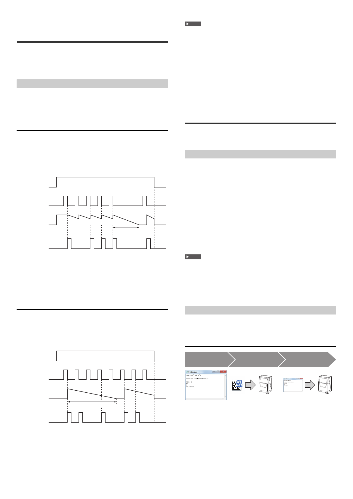
3-12
Timing input
Code
Data communication
Duplicate reading
prevention
Timing input
Code
Data communication
Duplicate reading
prevention
[1] Creating the script file [2] Changing the script
execution setting
[3] Transferring the script file
Duplicate reading prevention interval reset
The duplicate read prevention function is equipped with the Multi1 reading mode
not to read codes again that have been read once. The working time of this
duplicate reading prevention function is set by the duplicate reading prevention
interval. Two types of the duplicate reading prevention interval reset operation have
been prepared with the SR-750 Series.
Types of the duplicate reading prevention interval reset
Two types of the duplicate reading prevention interval reset
• Reset when a code is read.
• Do not reset during duplicate reading prevention interval.
This section describes each operation.
Reset when a code is read.
The duplicate reading prevention function works for one data most recently read. If
different codes are read, the duplicate reading prevention interval is reset and the
duplicate reading prevention function works for the newly read code data. The
duplicate reading prevention interval count starts at the timing when the last code is
read.
Timing chart
(1) (1) (2) (1) (2) (2)
Duplicate reading
(1) (2) (1) (2) (2)
• When reading is successful, reading continues using the successful bank until a
reading error occurs.
• If codes with the same contents are read in series, adjust the passing time longer
than the time set with the duplicate reading prevention interval (setting range:
100 to 25500 ms). Codes with different contents can be read in series.
• The timing to start measuring the duplicate reading prevention interval is when
the code that was read is outside the field of vision.
Do not reset during duplicate reading prevention
interval.
The duplicate reading prevention function works for all codes read within the set
duplicate reading prevention interval from when the timing input was done and the
first code is read. The duplicate reading prevention function works again when the
next code is read after the duplicate reading prevention interval finishes.
Timing chart
prevention interval
Important
If multiple codes in the same type are seen in the field of view at
the same time, take one of the following methods.
• Prepare multiple parameter banks with the read length
restricted, and make the setting so the parameter banks are
switched for each code.
• Prepare multiple parameter banks with the decoding area
restricted, and make the setting so the parameter banks are
switched for each code.
* When Multi read (setting within 1 parameter bank) is set to
Enable, if the code data that was read once matches with any of
the multiple read code data in 1 scan, not all code data read in
the scan are not output.
3-13
Edit data function/Edit image file name function
With the edit data function, read data can be edited into a desired data format.
With the edit image file name function, when sending image files to upper ranks via
FTP, the image file names can be edited into desired file names.
The edit data function and edit image file name function can do the following.
Edit data (Basic)
• Four arithmetic operations (add, subtract, multiply and divide)
• Conditional branching
• Adding arbitrary characters
• Extracting and combining arbitrary digits
Edit data (Advanced)
Various types of data can be built using four arithmetic operations, conditional
branching, etc. from appended data information, etc.
[Example]
• Code rotation angle (Calculated from top coordinates)
Edit image file name
• Time stamp*
• Append read data
Important
• The edit image file name function is available only for images
sent via FTP.
This does not function for images saved in RAM and ROM.
• This does not support quick setup codes.
* When using the time stamp, enable the SNTP function of SR-750
and connect to the SNTP server.
(For SNTP setting items, refer to Page 48.)
Procedure for setting the edit data function and edit image file name function
The edit data function and the edit image file name function can be used by
sending the file which contains the program of Script to SR-750 and enabling the
"Use script file" setting.
Setting procedure
(1) (2) (1) (3) (2) (1) (2) (2)
Duplicate reading prevention interval
(1) (2) (3) (1) (2)
• Regardless of reading success or reading error, codes are read alternating
parameter banks.
• Amount of data memorized during the duplicate reading prevention interval: Up
to 160 codes, total of 10 Kbytes
E SR-750 UM
[1] Creating the script file
Create the script file (FmtSet.lua) and write the program using a text editor such
as notepad.exe.
* For programming method, refer to "SR-D100/750 Series Script Reference".
24
Page 25
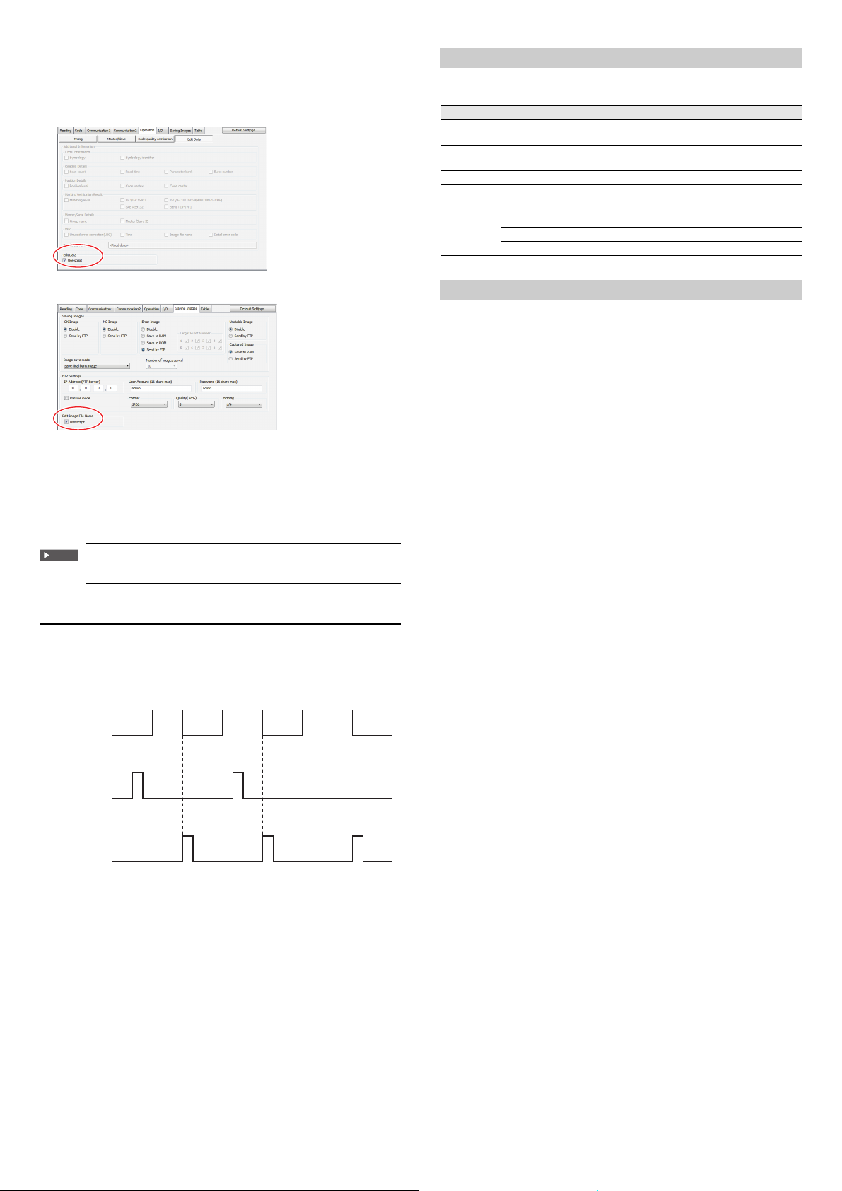
[2] Changing the script execution setting
Important
Timing input
Script file
transfer
Data
Image file name
Using the AutoID Network Navigator, set the script execution setting of the SR750 Series to "Enable".
This must be set for the edit data function and the edit image file name function
respectively.
[Edit data function - Script execution setting item]
Handing of the script file when settings are changed, etc.
This section describes how to handles the script file when restoring to the default
settings or using the changeover function.
Operation contents FmtSet.lua
AutoID Network Navigator "Retrieve
Configuration"
AutoID Network Navigator "Send
AutoID Network Navigator "Default Settings" Remains.
command
Configuration"
Send or delete by FileView Transmission and deletion possible from PC.
Reading quick setup codes Remains.
SAVE Remains.
Send
LOAD Remains.
DFLT Remains.
Receives with the configuration file at the
same time.
Sends with the configuration file at the same
time.
[Edit image file name function - Script execution setting item]
[3] Transferring the script file
Transfer the script file (FmtSet.lua) to the SR-D100 Series.
Following are the transfer methods.
• Sending configuration of AutoID Network Navigator
• Transferring only the script file from the AutoID Network Navigator terminal
• Transferring using the Fileview software
• Transferring using the FTP
When transferring the script file using the Fileview software or the
FTP, set the file name to "FmtSet.Lua".
Script file reflection timing
Even if the script file is in operation, transfer is possible each time by using the FTP.
In this case, the reflection timing of the script program is from the timing ON after
file transfer.
Timing chart
A
B
When executing the script file - status confirmation command
Obtaining the script processing time
Send command SCPTIME
Response OK, SCPTIME, now=AAus, max=BBus, min=CCus
AA: Returns the most recent script processing time.
BB: Returns the maximum value of the processing time.
CC: Returns the minimum value of the processing time.
• Returns the processing time of script executed after power ON.
Script debug setting
Send command SCPDBG, n
Response OK, SCPDBG
n= 0: Script debug OFF
n=1: Script debug ON
• This sets whether to output debug from the script file to the command port or
not.
• Setting the debug ON executes print(str) and outputs data.
Obtaining the script error results
Send command SCPERR
Response
OK, SCPERR, mmmmmmmmmmmmmmmmmmmmmmmmmmmmmm
mm… : Script error character string
• This returns the details of script error.
Obtaining the script version
Send command SCPVER
Response OK, SCPVER, mmmm, nnnn
mm...: Script library version
nn… : FmtSet.lua version
• FmtSet.Lua version is the value stored in variable name "SCPVERSION"
within the FmtSet.Lua file.
• This returns the script library version and the FmtSet.lua version.
• If the script library does not exist, the error code 12 is returned.
* The script library is a library file to use the edit data function and the edit image
file name function.
(Only when FmtSet.lua exists and the version is defined)
AA B
25
E SR-750 UM
Page 26
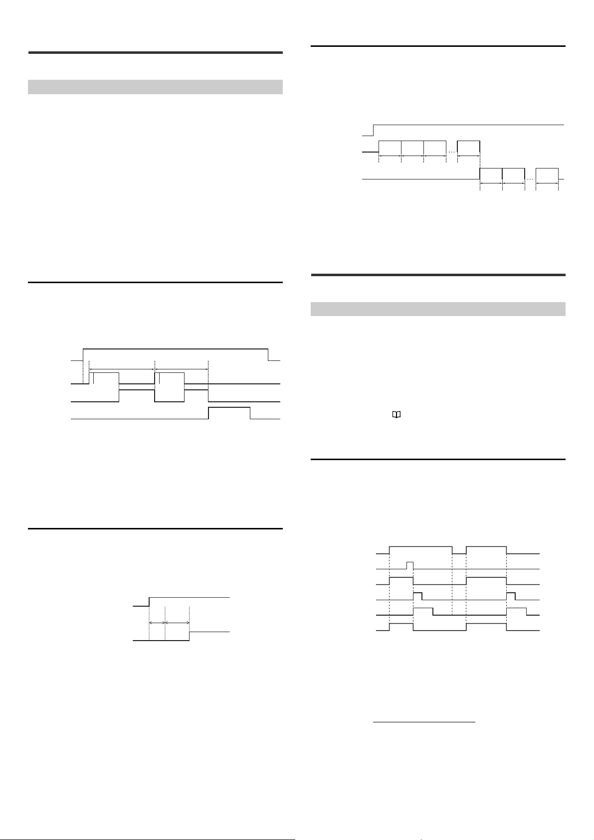
4-1 Reading Operations
A
B
B
D
C
C
F
(1) Trigger input
(2) S
canning +
image transfer
(3) Decoding
processing
(4) D
ata
communication
Operation of parameter bank 1
Operation of parameter bank 2
Read data
Trigger input
Scanning
Input time
constant
Scan delay
time
(1) Trigger input
(2) Parameter bank 1
operation
Internal bank retry
count = a
(3) Parameter bank 2
operation
Internal bank retry
count = b
Scanning +
decoding
0 times 1 time
2 times
a times
0 times 1 time b times
Scanning +
decoding
Scanning +
decoding
Scanning +
decoding
Scanning +
decoding
Scanning +
decoding
Trigger input
Code
Scanning + decoding
Data communication
TRG BUSY output
(When reading is successful) (When reading failed)
OK/NG/ERROR output
Data length + (1: When parit y is used) + Start/stop bits
Baud rate
This section describes the reading conditions of the SR-750 Series.
Steps of Read Operation
The SR-750 Series follow the read sequence below:
(1) Trigger input processing : Trigger input is verified and light is
controlled.
(2) Scanning + image transfer : The image is scanned within the specified
exposure time and the image is transferred.
(3) Decoding processing : The captured image is filtered and the code
is processed (decoded).
(4) Data communication processing : The decoded results are output as data.
Internal bank retry count
When the internal bank retry count is set, 1 parameter bank is repeated. When
decoding cannot be complete within the specified internal bank retry count,
operation to switch to the next parameter bank is possible.
If reading operation becomes unstable due to vibration of the workpiece, setting
the internal bank retry count enables stable reading.
Timing Chart
Since (2) and (3) above are based on the settings registered with the parameter
banks, operation is repeated using alternate banks until a code is read or the
trigger input is turned off.
Specify the following operations for the above processing:
• Timing Mode Specify from level trigger or one-shot trigger.
• Data Transmission Select "Send after read" or "Send after timing OFF".
• Read mode Specify from Single, Multi1, Multi 2 or burst.
Timing Chart
This section describes the steps of basic operations of the SR-750 Series.
Operating conditions are as follows:
• Timing Mode : Level trigger
• Timing to send data : Send after read
• Read mode : Single
• Parameter bank : Set 2 banks, alternate mode
A: Input time constant + Scan delay time
B: Exposure time set for each parameter bank (max. 9.99 ms)
C: Image transfer time (approx. 16 ms)
D: Decode time out period set for each parameter bank (Max. 2550 ms)
F: Decoding time when reading is successful
• The above is the image when reading is successful. For read error, B, C and D
are repeated continuously and read error data is output when the trigger input is
turned off.
Scan delay time
• The internal bank retry count can be set within the range from 0 to 32. (Factory
setting: 0)
• If a large number is set for the internal bank retry count and multiple parameter
banks are registered, reading time per time will become longer. Secure sufficient
reading time so that reading can be stable.
4-2 Timing Mode
This section describes the timing mode of the SR-750 Series.
Type of timing mode
The SR-750 Series provides the following 2 types of timing mode.
• Level trigger
• One-shot trigger
For the remainder of this section, assume the following settings are used:
• Read mode : Single
• Data Transmission : Send after read
• Output terminal settings OUT1 = OK
OUT2 = NG + ERROR
OUT3 = TRG BUSY
* Output terminal settings "3-6 Multi-I/O Function (Page 14)"
* For convenience sake, the timing chart does not indicate the input pulse width +
scan delay time.
Level trigger
When the trigger input turns on, the SR-750 Series turns on the illumination to start
scanning.
When a code is read successfully, it stops illumination and sends the data.
If the SR-750 Series fails to read a code, it stops illumination when the trigger input
turns off and sends a reading error.
Timing Chart
When the entry timing of the target to be conveyed is shifted from the input timing
of the timing sensor, set the "scan delay time".
This makes it possible to start scanning under optimum read conditions by setting
the delay for the timing at which emission of light of the SR-750 begins.
• The time can be set between 0 and 255 ms in increments of 1 ms (Default: 0 ms).
• Set the scan delay period for the parameter bank.
E SR-750 UM
OK/NG ERROR
• Set the trigger input so it stays ON from the reading start time until reading end
time.
• The illumination of the SR-750 Series turns on after the trigger input has been
activated for the specified input time constant.
• The input time constant for the trigger input can be changed to 1 ms, 2 ms, or 10
ms.
• The RS-232C data communication time can be obtained using the following
equation:
Data communication time= × (Number of digits of data to be sent +
Number of characters of header and terminator)
• The ON time for the OK/NG/ERROR output can be set within the range of 10 to
2550 ms (Default: 500 ms).
26
Page 27
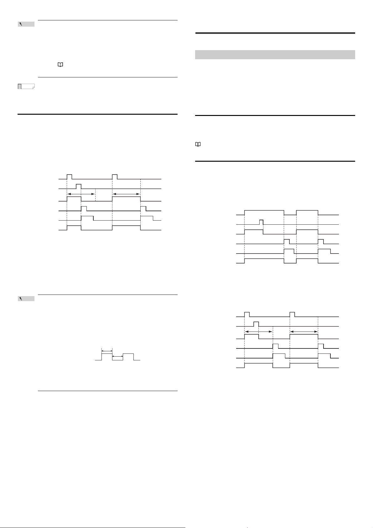
Point
When a code is read at an interval shorter than the specified
Reference
Point
OK/NG ERROR
Trigger input
Code
Scanning + decoding
Data communication
TRG BUSY output
(When reading is successful)
(When reading failed)
One-shot trigger duration One-shot trigger duration
OK/NG/ERROR output
Trigger input
a
b
Trigger input
Code
Scanning + decoding
Data communication
TRG BUSY output
(When reading is successful) (When reading fai led)
OK/NG/ERROR output
Trigger input
Code
Scanning + decoding
Data communication
TRG BUSY output
(When reading is successful)
(When reading failed)
One-shot trigger duration One-shot trigger duration
OK/NG/ERROR output
output ON time, the OK/NG/ERROR output turns off even if the
output ON time of the previous output signal has not elapsed, and
a new output signal turns on for the specified output ON time. If
output terminal operations of the same type occur successively
(such as OK→OK), the previous output signal turns off for 10 ms,
and then the new output signal turns on.
Refer to "Page 15 Function and Operation of the Output
Terminals (OUT1, OUT2 and OUT3)".
The TRG BUSY output turns on from the time the trigger input turns on
to the time the code reading is complete or the trigger input is turned
off.
One-shot trigger
When the SR-750 Series detects that the trigger input is on, it turns on the lighting
for the specified one-shot trigger duration to scan a code.
When a code is read successfully, it stops illumination and sends the data. Other
operations are the same as those for the level trigger.
Use the one-shot trigger if the ON time of the trigger input is extremely short or if
you want to fix the read time.
Timing Chart
4-3 Data Transmission Timing
This section describes the data transmission timing of the SR-750 Series.
Type of data transmission timing
The SR-750 Series offers the following 2 options for outputting the read data and
OK/NG/ERROR signals:
• Send after reading
• Send after timing OFF
Select the appropriate type for your application.
* For the sake of simplicity, Input time constant + Scan delay time is not shown in
the timing chart.
Send after reading
The SR-750 Series outputs read data and an OK/NG signal as soon as it
completes reading codes. If the SR-750 Series fails to read a code, it outputs a
read error code and an ERROR signal at the point when the timing signal turns off.
The timing charts are the same as those shown in "Timing Mode".
"4-2 Timing Mode (Page 26)"
Send after timing OFF
When "Send after timing OFF" is selected, the SR-750 Series outputs read data
and an OK/NG/ERROR signal at the next timing point for the specified trigger type.
Use this type to output data and output signals with the same timing.
Timing Chart for the level trigger
When the trigger input turns off, read data and OK/NG/ERROR signal are output.
• When the trigger input stays on for the specified input time constant, the
illumination of the SR-750 Series turns on and the scanning begins.
When the reading is complete, the illumination stops.
• The input time constant for the trigger input can be changed to 1 ms, 2 ms, or 10
ms.
• The one-shot trigger duration can be changed within the range of 100 to 25500
ms.
• If the SR-750 Series fails to read a code within the one-shot trigger duration, it
stops illumination and outputs a reading error.
• Other operations and precautions are the same as those for the level trigger.
The ON state of the trigger input is recognized after the input stays
on for at least the specified input time constant.
The OFF state of the trigger input is recognized after the input
stays off for at least the specified input time constant.
Consequently, when the line speed is fast and fast pulse signals
are used as trigger input signals, be careful to make the ON/OFF
time of the pulse signals longer than the specified input time
constant.
Trigger input time constant = when a, if a becomes larger than b,
the OFF state of the trigger input is not recognized.
When a ≤ b, the ON/OFF state of the timing signal can be
recognized.
OK/NG ERROR
• When a code is read successfully, the read operation stops.
• The TRG BUSY output continues until the trigger input turns off.
Timing Chart for the one-shot trigger
When the specified one-shot trigger duration elapses, the read data and OK/NG/
ERROR signal are output.
OK/NG ERROR
• When a code is read successfully, the read operation stops.
• The TRG BUSY output continues until the one-shot trigger duration elapses.
27
E SR-750 UM
Page 28
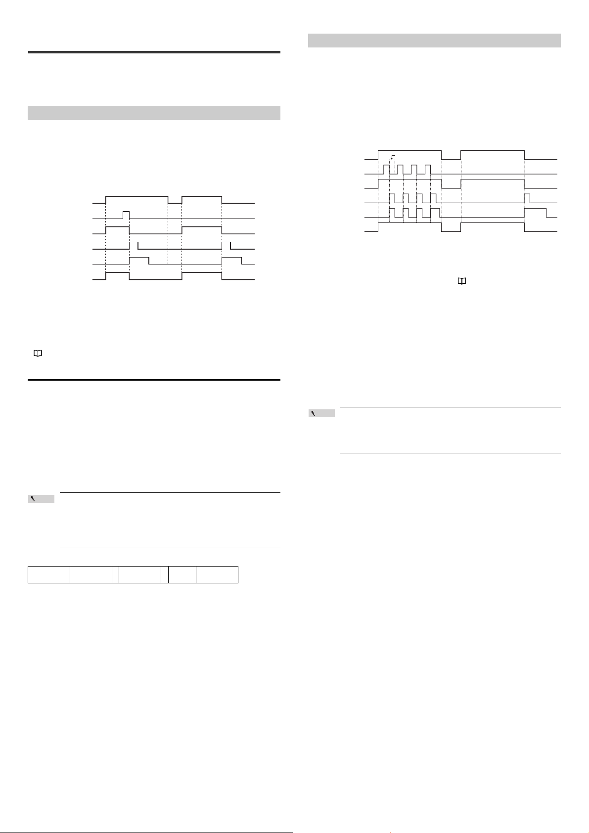
4-4 Read Mode
Point
OK/NG ERROR
Trigger input
Code
Scanning + decoding
Data communication
TRG BUSY output
(When reading is successful) (When reading failed)
OK/NG/ERROR output
Trigger input
Code
Scanning + decoding
Data communication
TRG BUSY output
(When reading is successful) (When reading fail ed)
OK/NG/ERROR output
OK
/
NG
ERROR
OK
/
NG
OK
/
NG
OK
/
NG
Duplicate reading
prevention interval
The SR-750 Series offers 4 types of read modes. Select the appropriate type for
your application. For most applications, use "Single read mode".
* For the sake of simplicity, Input time constant + Scan delay time is not shown in
the timing chart.
Single read mode
In this mode, the SR-750 Series reads a single code while the trigger input is
turned on once, and then outputs data.
Scanning will not begin again until the timing input is first turned off, then back on
again.
Timing Chart
* The above timing chart shows the case where "Level trigger" and "Send after
reading" are selected.
• In single read mode, the data transmission timing can be selected from "Send
after reading" or "Send after timing off".
• The timing mode can be selected from "Level trigger" or "One-shot trigger".
• Scan interval is automatically set so that decoding processing can be
implemented efficiently.
"4-1 Reading Operations (Page 26)"
Multiple Code Reading in Single Read Mode
Normally, the single read mode is used to read 1 code from 1 timing input signal.
When the following read setting conditions are specified, multiple codes within the
field of view can be read with 1 timing input signal.
Setting "Multi read" in the code detail settings
When "Multi read" is selected in the code detail settings, multiple codes can be
read in 1 reading operation.
• Use the AutoID Network Navigator or setting command to set.
• The number of codes for multiple readings can be set between 2 and 16
• When "Allow reduced detection count" is selected, the reading is considered
successful if at least 1 code is read successfully.
Multi 1 Read Mode
In this mode, the SR-750 Series reads multiple codes in succession while the
trigger input is turned on once.
In Multi 1 read mode, the SR-750 Series sends out data and outputs an OK signal
every time it reads 1 code (or an OK/NG signal when preset data is registered).
The SR-750 continues to scan while the trigger input is on even if no code is
present. ERROR will only be output if no code is read after the trigger signal is
turned off.
Timing Chart
• The SR-750 Series reads codes in succession for the following duration:
Level trigger : While the trigger input is turned on
One-shot trigger : During the specified one-shot trigger duration
• The duplicate reading prevention operation changes according to the setting of
the duplicate reading prevention interval reset. "3-12 Duplicate reading
prevention interval reset" (Page 24)
• When codes with the same contents are read in succession, adjust the moving
speed so that the codes pass at intervals longer than the specified duplicate
reading prevention interval (Setting range: 0 to 25500 ms). Codes with different
contents can be read at shorter intervals.
• Each time scanning is performed in Multi 1 operation, the laser pointer lights up.
The lighting period for the laser pointer is set on "Laser-aimer blinking duration (0
to 990 ms)" and the scanning is not performed during this period.
• The data transmission timing for Multi 1 is "Send after read" only.
• In Multi 1 operation, the availability of the image save function is as follows.
Saving images
• Read OK/NG ...Cannot be used
• Error image .....Can be used
Point
When Multi 1 read mode is selected using the AutoID Network
Navigator, the decode timeout is set to 500 ms. To shorten the
decode timeout period, change the decode timeout setting of each
parameter bank manually.
• In this setting, multiple codes of different types cannot be read
in 1 read action.
• Codes are output in order starting from the code coordinates
above the upper scan screen (if the height is the same, from the
left).
• The output data format is as follows:
Header The 1st data , The 2nd data , ··· Terminator
E SR-750 UM
,= Inter delimiter: Can be changed with setting
(Default = "," (0x2C))
28
Page 29
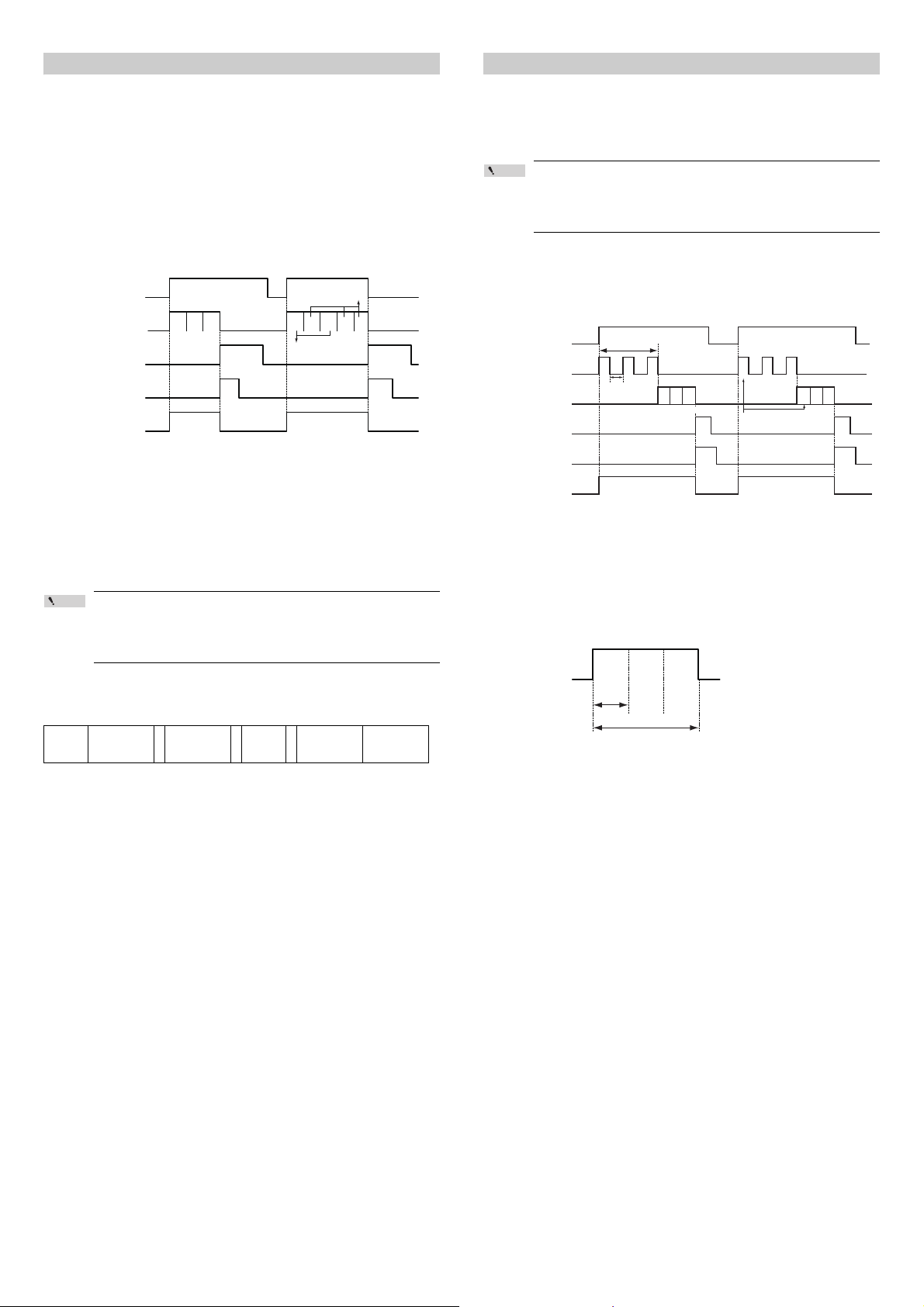
Multi 2 Read Mode
Point
OK/
NG
(1) (2) (4) (1) (2) (4) (2) (2)
ERROR
Trigger input
Scanning + decoding
Data communication
OK/NG/ERROR output
(When reading is successful) (When reading failed)
TRG BUSY output
Read error
Reading success
Parameter bank No.
Trigger input
Scanning
Decoding
OK/NG/ERR LED output
<When reading is successful> <When reading failed>
TRG BUSY output
Data communication
(1) (2) (3)
Decoding
Decoding
failed
Decoding
failed
Decoding
succeede
Decode timeout
Decoding time
Burst scan
No.
Burst scan
No.
Burst scan
No.
Multi 2 read mode is used to read the codes in the parameter banks with registered
settings in order while the trigger input is turned on once.
After reading all codes (max. 10 types) registered with the parameter bank, this
function sends the read data in the order of parameter number and outputs OK/NG
signals.
If no code is read while the trigger input is turned on or if even one code set for a
parameter bank is not read, the SR-750 Series sends a reading error and outputs
an ERROR signal for the unread code in the parameter bank after the trigger input
turns off.
Timing Chart
Timing charts when registered with the parameter banks 1, 2 and 4 are as follows:
Burst Reading Mode
The burst reading mode is a function to repeat scan up to a maximum of 8 times in
succession and perform decoding after the scanning is complete.
When, for example, the line speed is fast and accurate positioning is difficult, this
function ensures scanning without missing codes by repeating scans only for the
period during which the target is expected to pass.
Point
• The alternate function cannot be used in Burst reading mode.
Decoding is performed with the specified parameter number.
• In Burst reading mode, the No. of repeat read attempts setting is
ignored.
Timing Chart
The following is the timing chart when the Burst reading mode is used. (Burst scan
count: 3)
No. of burst scans
• The SR-750 Series reads codes in succession for the following duration:
Level trigger : While the trigger input is turned on
One-shot trigger : During the specified one-shot trigger duration
• An OK signal is output when all of the codes of the set parameter banks are read.
• An ERROR signal is output when even 1 specified code could not be read.
• Even when there are multiple codes within the reading range, all codes can be
read simultaneously.
• Each time scanning is performed in Multi 2 operation, the laser pointer lights up.
The lighting period for the laser pointer is set on "Laser-Aim pulse duration (0 to
990 ms)" and the scanning is not performed during this period.
When Multi 1 read mode is selected using the AutoID Network
Navigator, the decode timeout is set to 500 ms. To shorten the
decode timeout period, change the decode timeout setting of each
parameter bank manually.
Output data format
The following output data format is used for the read data.
Header
Read data in
parameter bank
No. 1
• Each read data is separated with "," (0x2C: Intermediate delimiter).
• The data for the read bar codes is saved in the send buffer of the SR-750 Series
once and then is output when all configured banks have been read or the timing
input is turned off. The size of the send buffer of the SR-750 Series is 10 KB.
• If reading fails for any of parameter banks 1 to 10 or if the specified code is not
found, ERROR is sent as the read data of the corresponding parameter bank
number.
Read data in
,
parameter bank
No. 2
,...,
parameter bank
Read data in
No. 10
Terminator
(1) (2)
(3)
Burst scan interval
(1) (2) (3)
(Failed) (Failed)
(Succeeded)
OK/NG
(2) (3)
(1)
Burst scan No.
(1) (2) (3)
(Failed) (Failed) (Failed)
ERROR
• In Burst reading mode, the scanned data is decoded in the order in which it was
obtained.
If decoding fails after the decode timeout period elapses, the decoding is shifted
to the next scanned data.
• The data communication is output when the decoding is successful or decoding
of all scan data is failed.
The decoding time when decoding succeeds for the third scanned data is as
follows:
• If the trigger input turns off with the decoding processing unfinished, reading error
occurs. Secure longer time for the trigger input ON than the time calculated by
(scan + burst scan interval + decoding timeout time) x burst scan count.
• The data transmission timing for the Burst reading mode is "Send after read"
only.
29
E SR-750 UM
Page 30

5-1 Installing, Starting, and
disc JP
EN
CHT
CHS
DE
manual
AutoIDLauncher.exe
AutoIDLauncher.ini
JP
EN
CHT
CHS
DE
JP
EN
SetupPrerequisites dotnetfx35.exe
setupNF.exe
languagepack
AutoIDNetworkNavigator
Multimonitor
FileView
Setup
firmware
EDS
GSDML
Windowssampleprogram
Manual data in PDF format
SR-D100/750/650 Series main unit firmware
EDS file for EtherNet/IP
GSDML file for PROFINET
Sample program of Visual Basic, C# and C++
Important
• To install AutoID Network Navigator, log on as a user with
rights to change the system configuration, such as
Administrator or Computer Administrator.
• Quit all active applications before starting the installation.
The installation may take longer if antivirus software or other
applications are active on the computer.
Shutting Down
This section describes how to install AutoID Network Navigator as well as how to start
and shut down the application.
PC Requirements
Before starting installation, confirm that your PC meets the following requirements:
Supported OSs
• Windows XP (SP3 or higher) 32-bit version
• Windows Vista (Business/Ultimate, SP2 or higher) 32-bit version
• Windows 7 (Professional or higher) 32-bit version/64-bit version
• Windows 8 (Windows RT excluded)
* NET Framework 3.5 SP1 or later must be installed in advance.
* When installing .NET3.5 on Windows 8, the Internet environment is necessary.
* When installing .NET3.5 on Windows 8, operate from the control panel.
Hardware
32-bit 64-bit
Processor 2.0 GHz
System Memory 1 GB 2 GB
DVD-ROM Drive Required for installation
Communication Port Ethernet port
Precautions
• To install AutoID Network Navigator, log on as a user with rights to change the
system configuration, such as Administrator or Computer Administrator.
• Quit all active applications before starting the installation. The installation may
take longer if antivirus software or other applications are active on the computer.
Trademark
Windows 8/Windows 7/Vista/XP is a registered trademark of Microsoft Corporation
in the United States.
Installation Flow
1 Turn ON the PC and start Windows.
2 Insert the "AutoID Network Navigator Master Disc" into the DVD-
ROM drive of the PC.
3 Normally, the AutoRun function of the computer will display the
following screen.
To start the installer directly, use Windows Explorer or another
method to open the DVD-ROM drive, and double-click "AutoID
Launcher.exe" in the Setup folder.
AutoID Launcher will start and select the language of the installer software.
4 The AutoID Network Navigator installer will start.
Install Method
This section explains installation using the following drive configuration under
Windows 7 as an example:
Drive C: Hard disk drive
Drive E: DVD-ROM drive
Folder Structure
The folder structure on the master disc is as follows.
E SR-750 UM
5 Click "Install .NET Framework 3.5 SP1".
If .NET Framework 3.5 SP1 is already installed in the computer to be used,
then the install will automatically exit.
• If .NET Framework 3.5 SP1 is not installed, follow the on-screen instructions
to continue with the installation.
6 Click "Install AutoID Network Navigator".
7 Click "Next".
8 Click "Next".
Click on the [Change] button to change to the folder in which the application will
be installed.
30
Page 31

9 Click [Install].
10
Click [Finish].
11
Follow the same steps to "Install FileView" and "Install
MultiMonitor".
Uninstall Method
From the Start menu, select [Control panel] -> [Programs] -> [Programs and
Features] -> [Uninstall or change a program], select the program to uninstall from
the list, and click [Uninstall].
Startup Procedure
Starting AutoID Network Navigator
From the Start menu, select [Programs] → [KEYENCE Applications] → [AutoID] →
[AutoID Network Navigator (EN)].
Or, double-click on the desktop.
AutoID Network Navigator will start up.
Select the network card to use first.
FileView install screen
MultiMonitor install screen
When automatically detected
If the SR-750 Series unit is within the same network, then this will be automatically
detected, and the following window will be displayed.
When not automatically detected
If the SR-750 Series unit is not automatically detected, then the following message
will be displayed.
31
E SR-750 UM
Page 32

Adding Reader with Register Button
Important
To add the SR-750 Series on the different network, default
gateway must have been preconfigured to the SR-750 Series.
• To set a temporary IP address, the SR-750 Series must be on
the same network.
Temporary IP address cannot set for a SR-750 Series on the
different network.
• Temporary IP address setting is a function to communicate
with AutoID Network Navigator.
IP address and subnet mask etc. for the SR-750 Series must
be set according to the network to use.
• The IP address set using the Temporary IP Address Settings
is canceled when the main unit is reset. When the unit is
being connected temporarily due to maintenance, etc., turn
the power on again after the setting is complete, or perform
the main unit reset by sending the RESET command.
When a temporary IP address has been set,
the IP address is displayed in light blue .
If the SR-750 Series is on the different network, or it is placed on the network after
starting AutoID Network Navigator up, add the reader by clicking the Register
button.
1 Click the Register button .
2 If the SR-750 Series is on a different network, click the Add button
and enter the IP address of the SR-750 Series to add.
Adding Reader with Temporary IP Address Settings
Temporary IP address is used if the IP address for the SR-750 Series is unknown
or the IP address of the SR-750 Series to register is conflicting within the network.
1 Click the Apply temporary IP address button.
2 Press the TUNE button of the SR-750 Series for 5 seconds until 4
multiple LEDs light up.
For button operation details, click here to display the button operation
description window.
3 When the address is detected, the reader information is displayed as
follows:
3 To have a SR-750 Series unit participate on the network after starting
AutoID Network Navigator, click the [Auto Search] button and add
the SR-750 Series unit.
To add all searched readers, check "Check all".
To add only a certain reader, uncheck "Check all" and check the reader to add.
4 Click the [Register] button.
The SR-750 Series unit will be registered in the reader view, and will be usable
by AutoID Network Navigator.
If the IP address shown is correct, click the OK button.
To change the IP address, click the Change button to change the IP address.
To add all readers detected, check "Check all".
To add only a certain reader, uncheck "Check all" and check the reader to add.
Important
E SR-750 UM
32
Page 33

5-2 Screen Layout
(7)(4)
(1)
(2)
(3)
(5)
(6)
(8)
Menu Bar
This section describes the icons for AutoID Network Navigator.
Screen
(1) : Menu Bar
Some operations of the AutoID
Network Navigator functions or
software version can be checked.
(2) : File Icon
…Creates a new file.
…Opens a file.
…Saves on an existing file.
(3) : Edit Icon
Undo the current work or redo.
(4) : Tool Icon
Starts each tool of AutoID Network
Navigator.
(For details of each tool, refer to
Page 51 or later.)
(5) : System icons
Register items on AutoID Network
Navigator, remove items, or
change settings.
… Register button. Register
the SR-750 Series unit in
AutoID Network Navigator.
… Change settings button.
Open a configuration file.
… Delete button. Delete a SR-
750 Series unit from AutoID
Network Navigator.
… Update button. Update the
connection with the SR-750
Series unit to the latest
status.
(6) : Reader list
Displays search results or reader
information for the detected
readers or an open file.
Registration of a new reader or
deletion of a displayed reader can
also be performed.
(7) : Transmission and reception
settings icon
Prints quick setup codes or sends/
receives a configuration.
(8) : Configuration View
While confirming SR-750 Series
unit read images, carry out quick
calibration or configure
transmission settings or
operations modes.
(For details of the Configuration
View operation, refer to Page
35.)
… Click to reset the configuration
to default.
File
Edit
View
System
Transfer
• New : Creates a new configuration
• Open : Opens a configuration file.
• Save : Saves the selected file.
• Save As : Saves the selected file with a
• Save All : Saves all opened files.
• Quick Setup Code : Prints the settings of the
•
Export Reader Configuration
•
S
ave serial number : Not used with the SR-750
• Report Generator : Uses the report generator
• Undo : Goes back to a previous state.
• Redo : Performs an operation again.
• Reader View : If the checkmark is removed,
•
Highlight Configured Fields
• Register : Registers a reader. For details,
•
S
witch reader configuration
• Delete Reader : Deletes a registered reader
•
Temporary IP Address Setting
•C
onfirm Firmware Version
• Update Firmware : Updates the system firmware.
•
Retrieve Configuration
• Send Configuration : Sends a configuration.
file.
new name.
selected file with the quick
setup code function. For
details, refer to Page 50.
: Outputs the selected file list to
a tab separated text file. For
details, refer to Page 54.
Series.
function. For details, refer to
"5-14 Report Generator
Function (Page 55)".
then the reader list will close.
: Highlights the parts changed
from the factory configuration.
refer to Page 32.
: Switches to the other
configuration file.
from a list.
: Assigns a temporary IP
address.
: Display the IP address, unit
system version, and MAC
address of the selected reader.
: Receives a configuration.
Tool
• Live View : Starts the LiveView function. For
• Image View : Starts the ImageView function. For
• FileView : Starts the FileView function. For
• Terminal : Starts the Terminal function. For
•
Installation Guide
33
details, refer to Page 51.
details, refer to Page 52.
details, refer to Page 53.
details, refer to Page 50.
: Starts the Installation Guide. For
details, refer to Page 53.
E SR-750 UM
Page 34

Configuration
Search Readers on
Application Startup
Terminal on Live
View Startup
Select a reader to configure from the automatically searched readers. Or
register the reader to configure.
1
Configure the operation of the SR-750 Series
Page 34
2
Send the configuration to the SR-750 Series
Page 49
3
Perform a reading test
Page 35
4
Save/print the configuration as necessary
Page 49, 54
5
Shut down AutoID Network Navigator
6
•
• Option window
Select Network Card
• Options : Click to open the Option
•
•
Clock Sync (SR-D100)
•
Communication Timeout
• : Select to display the terminal
: Selects a network card for the
PC to use with AutoID Network
Navigator.
window.
: Sets whether to search
automatically a SR-750 Series
at the AutoID Network Navigator
startup.
: Not used with the SR-750
Series.
: Sets the communication
timeout for AutoID Network
Navigator to either 5 or 10
seconds.
together when Live View is
started.
Help
•
About : Displays the version information of AutoID
Network Navigator.
The Reader List
AutoID Network Navigator communicates with the connected SR-750 Series unit at
specified intervals. The indicator displayed to the left shows the status of
communications.
Lamp status Description
Green SR-750 is registered in AutoID Network Navigator.
SR-750 is operating in AutoID Network Navigator.
* During operation, this will halt the command port
Blue
connection and data port connection with other
communication devices.
AutoID Network Navigator and SR-750 are not
Gray
communicating.
An SR-750 formerly in communication can not be
recognized.
Check that the IP address has not changed, or that
Red
the Ethernet cable has not been removed.
When communication is possible, the indicator will
automatically change to green.
Operations that can be carried out on the reader list
The following operations can be carried out on the reader list.
• Click the indicator to change the status of communications between AutoID
Network Navigator and the SR-750 Series unit.
• When the mouse pointer is placed on any of the reader name, IP address, or
model, then the MAC address of that SR-750 Series unit will be displayed.
• Right-clicking on any of the reader name, IP address, or model will enable
selection of registration, deletion, or changing of configuration of the reader.
• These details can be selected from System in the menu bar.
5-3 AutoID Network Navigator
Operation Flow
The basic operation flow of AutoID Network Navigator is as follows:
5-4 Details of Settings View
This section describes details and operating methods in settings view for AutoID
Network Navigator.
[Camera] tab
The [Camera] tab has [Auto] and [Manual] methods for registering with the
parameter bank.
• Auto : Mode for carrying out quick calibration of the SR-750 Series unit.
Click Positioning → Tuning → Test to automatically configure the
optimum settings.
• Manual : Enables quick configuration of details of reading settings that cannot
be configured in quick tuning.
This section explains details of this screen.
• Double-click the IP address to specify the IP address of the connected reader.
• Used to change the SR-750 communicating with AutoID Network Navigator.
E SR-750 UM
34
Page 35

The [Auto] screen
(5)
(1)
(6)
(7)
(2)
(3)
(4)
(8) (9)
(1)
(2)
(3)
(4)
(5)
(6)
(7)
(8)
In the standard condition, the switch side of the
SR-750 Series faces to the top.
Top
Bottom
(1)
(2)
(3)
(4)
(1) Configuration procedure
Buttons to switch between [Auto] and [Manual] modes.
(2) Positioning
Laser-Aim … Activate the laser-Aim of the SR-750 Series.
Monitor … Displays the image output by the SR-750 Series.
Automatically measures reading rate at the same time.
Monitor Settings…Sets the display during monitor operation.
(3) Tuning
Tuning…Performs a calibration.
Tuning option … Sets the calibration method.
Tuning History… Displays the history of calibrations.
(4) Test
Reading test…Starts the reading rate test mode.
Tact test … Starts the read time test mode.
Bank … Check to start the test mode using a bank selected at (8).
If not checked, the test mode is started with the Alternate function
activated.
(5) Monitor screen
Displays the image output by the SR-750 Series.
Dragging on the screen or operating the orange guide can restrict the tuning
range. The position of the restricted tuning range can be changes by further
dragging.
Monitor Settings
Camera settings
(1) : Brightness adjustment mode
High quality mode…Adjusts the monitor
screen brightness with
easiness to view codes
prioritized.
High speed mode…Adjusts the monitor
screen brightness with
the (2) setting prioritized.
(2) : Exposure on high speed mode
Upper limit of exposure when capturing
images
(3) : Offset
Sets the offset value (brightness base
value).
Do not change normally.
(4) : Dynamic range
Sets the dynamic range when capturing images.
Setting range: Hi-Sensitivity/Hi-SNR, Hi-DR
Monitor Settings
(5) : Internal Lighting
Selects whether to use lighting of the SR-750 Series main unit.
(6) : External Lighting
Selects when using the external lighting. To interlock operation of the SR-750
Series with emission of external lighting, assign "EXT.LIGHT" to the output
terminal.
(7) : Displayed image
Selects the displayed image from images before filter-processed or images
after filter-processed.
(8) : Rotate image
Images output from the SR-750 Series can be rotated 180 degrees.
The direction for easy adjustment can be selected according to the mounting
condition of the SR-750 Series.
TEST TUNE
SR-625
NETIN
POWERR
OK/NG/
STB
* Clicking the (7) "Full area" button can reset the restricted tuning range.
(6) Brightness adjustment bar
Adjust the brightness of the monitor screen.
(7) [Full area] button
Resets the decoding area restricted on the monitor, and returns the decoding
area to the full field of view.
(8) Parameter bank display window
Displays the current parameter bank settings.
(9) Camera status display window
Displays quick tuning status and test mode result values.
Tuning Options
Tuning tab
Camera settings
(1) : Camera settings
Same as for the monitor settings
Tuning Options
(2) : Tuning method
Normal........ Performs tuning without
Filter ........... Performs tuning with image
(3) : Multi read
The multi read mode reads multiple
codes of the same type with one
parameter bank.
Multi read ... Check to enable multi read.
Allow reduced detection count…
(4) : Rotate image
Disable .......Searches black codes with white background.
Able ............ Searches white codes with black background.
Auto............ Searches automatically detecting the color (black/white) of code
35
image process filter.
process filter.
Set the number of codes to be read from 2 to 16.
Check this to approve reading success even if the number of
codes read is less than the set number.
and background.
E SR-750 UM
Page 36

Symbology tab
(1)
(2)
Code setting
(5) : Symbology
Specify the code type for tuning.
(6) : Code-specific setting
Set the read length and detailed conditions
of each code.
For read length and detailed conditions,
refer to [Code] tab (Page 38).
(5) (6)
Parameter Bank Display Window
• Alternate … Displays whether to use the alternate function.
• Code type … Code type to perform reading. 1 code type for each bank is
• Exposure (μs) … Sets the exposure time to scan an image.
• Gain … Amplifies the brightness of the scanned data.
• Dynamic range … Displays the dynamic range for scanning.
• Filter … Displays the filter type for scanning.
• Filter count … Displays the number of filtering times.
When Alternate is set to "Disable", the corresponding
parameter bank will not be used.
displayed.
Reading State Window (During Calibration)
(1) : Level
Displays the matching level.
(2) : Brightness
Divided in 128 comprehensive
image brightness phases
according to the factors such as
dynamic range, gain and
exposure.
• Plot colors, when filtering function is activated
Color Filter name Color code (RGB)
●: Black Disable 0,0,0
●: Yellow-green Equalize 68,192,0
●: Green Expand 0,130,58
●: Light blue Shrink 0,183,238
●: Blue Open 0,67,238
●: Purple Close 171,0,242
●: Orange Unsharp Mask 255,138,0
Details of the Tuning History screen
Click button to display the following screen.
It is possible to select what is considered the optimal calibration results when
carrying out multiple calibrations for the same code, and register these in the
parameter bank.
•History
Displays a maximum of 8 results of calibration.
The latest calibration results are displayed at the top in position (1).
Multiple history data results can be combined and displayed on a calibration
results chart.
•Update
A button to reflect the calibration results selected in the history in the parameter
bank selected in the reading settings.
•Clear
Deletes all collected calibration history.
• Reading settings
Use the bank update button to select the parameter bank No. to update.
You can also confirm detailed values for updated calibration results.
• Tuning image
Displays image obtained at calibration, when selected in the history.
• Tuning result
Displays graphs from calibration, when selected in the history.
The [Manual] screen
Click the [Manual] button to list items that can be configured in the SR-750 Series
parameter bank.
Use this to check result values obtained in the [Auto] screen, and to manually
change parameters.
Reading State Window (Reading Rate)
• Parameter bank … Displays the bank
number used for reading.
• Reading test … Displays a reading rate.
• Matching level … Displays a matching
level.
• Read Data … Displays data when the
reading was successful.
Reading State Window (Tact Test)
• Bank number … Displays the bank number
used for reading.
• Read time … Displays the latest read
time.
• Max time … Displays the maximum
read time.
• Min time … Displays the minimum read
time.
• Read Data … Displays data when the
reading was successful.
E SR-750 UM
36
Page 37

Common
•Alternate
Enable: read the selected parameter bank, and use for reading operations.
Disable: do not use the selected parameter bank.
• Repeat read attempts
Set the number of repeat reads for the selected parameter bank within the range
of 0 to 32.
* This specifies the number of retries, therefore if "02" is set, then after a single
read, 2 retries will be carried out.
• Decode timeout (×10 ms)
The timeout value set in auto calibration.
Set values can be specified manually from 10 ms to 10000 ms (Unit: 10 ms).
•Shutter delay
Set the delay between the recognition of a trigger input and the scanning start.
Default : 0 ms
Setting range : 0 to 255 ms
• Decode range
Set the range of scanning and decoding.
• Inverse read
Inverse read settings during calibration.
• Reverse read
Reverse read (reverse surface) settings during calibration.
• Base tilt angle
Sets the base angle for a tilt angle range to limit reading.
When DataMatrix is set, the finder pattern rotates until it appears as an "L". When
the QR code is set, the corner without a finder pattern will become the bottom
right corner and 0 degrees. The angle rotates in the clockwise direction
(anticlockwise for Reverse read).
Default : 0 degrees
Setting range : 0 to 359 degrees
•Tilt angle range
Sets a tilt angle range to limit reading. Specify with ±* degree to the base tilt
angle.
Default : 180 degree
Setting range : 0 to 180 degree
Code
• Code type
Code type set in the parameter bank.
• Code setting
Maximum and minimum values for read digits in the parameter bank.
• Code detail setting
Confirm and change detailed settings for each code item set in the parameter
bank.
Additionally, multiple read conditions can be set here.
• Output length limitation
Set the output length limitation function.
Default: if enabled, then set the following items.
• Mode
Set the direction of the range of the output length limitation function.
Forward : set the effective digits and start digits for restrictions from the front of
the code data.
Backward : set the effective digits and start digits for restrictions from the end of
the code data.
• Start of output
Set the number of digits for output length limitation.
• Starting index of output
Set the number of digits for the start of output limiting within the code data.
* This item can also be set from the [Code] tab.
Light
• Use internal lighting
Set whether or not to use internal lighting.
Default: Enable
• Use external lighting
Set whether or not to use external lighting.
Default: Disable
Scan
• Exposure
The exposure set in auto calibration.
This can also be set manually from the drop-down menu.
•Gain
The digital magnification ratio for brightness of the scan data set in auto
calibration.
Default: 10000
This can also be set manually from the drop-down menu.
• Offset
The offset value for the scan data set in auto calibration.
Gain processing is performed based upon the value set as the offset.
Do not change the setting value under normal conditions.
• Dynamic range
The dynamic range set in auto calibration.
Default : High sensitive
Setting contents: Hi-Sensitive, Hi-SNR, Hi-DR
• Sensitivity
The analog magnification ratio for brightness of the scan data set in auto
calibration.
Default: 10000
This can also be set manually from the drop-down menu.
Filter
• First manual filter
Sets the filter to perform for the scanned data.
Default : Disable
Setting range : Disable, Equalize, Expand, Shrink, Open, Close, Median, or
• First manual filter count
Sets the repeat times to perform the first filtering operation specified.
Default : 1
Setting range : 1 to 7
• Second to Fourth manual filters…Same as First manual filter.
• Second to Fourth manual filter counts…Same as First manual filter count.
Unsharp Mask
Algorithm
• Grid correction
Sets to either Enable or Disable for the grid correction.
Default : Disable
Setting range : Enable or Disable
To copy or paste a parameter bank, right click on the bank number and
Reference
then perform copy or paste operation for the target parameter.
Screen image
37
E SR-750 UM
Page 38

[Code] tab
Reference
(1)
(2)
(4)
(3)
KEYENCE–SR–75 0
YENCE
Forward
Origin: 3
Length: 5
∴Output data:
KEYENCE–SR–75 0
–SR–7
Backward
Origin: 3
Length: 5
∴Output data:
DataMatrix QR
.....Check this to send read
data, including the start/
stop character (*), to the
host computer.
.....When this option is
checked, [Send checkdigit] is enabled.
Send check-digit............... Check this to send read
data, including the check
digit, to the host
computer.
Quiet zone scale factor (4-11)
....Set the quiet zone scale
factor.
Full ASCII conversion....... Recognizes CODE39 as
"CODE39 FullAscii" and
output.
Send start/stop
characters (*)
Inspect check-digit
[Modulus 43]
In the [Code] tab, set read digits for symbology registered in each parameter bank,
as well as detailed items and output length restrictions for each code.
Furthermore, settings items in the [Code] tab set the same items as those in the
[Camera] tab, Manual section.
Change settings in one of these.
(1) Bank bb Coded Settings
Symbology set in the parameter bank number (1 to 10). Displays the
symbology set in auto calibration.
Additionally, for each symbology set here, maximum values for read digits are
changed, as well as detailed items using the [Details] button.
Symbology that can be set in parameter banks are as follows.
1: QR 7: ITF
2: DataMatrix 9: NW-7 (Codabar)
5: GS1 DataBar (RSS) 10: JAN/EAN/UPC
6: CODE39 11: CODE128
(2) Number of digits read
Set maximum and minimum values for digits read. Click the [Edit] button to
change the maximum and minimum values.
The maximum and minimum values can be set to the same values, and the
number of read digits restricted.
Permissible setting ranges for each symbology are as follows.
Symbology Maximum value Minimum value
QR 7089 1
DataMatrix 3116 1
GS1 DataBar (RSS) 77 1
CODE39, NW-7 50 3
ITF 50 2
CODE128 128 1
Depending on the marking conditions or operation environment,
cancellation of significant digits of NW-7 (Codabar) codes may occur or
the code may be mistakenly read. It is recommended to restrict the
read length.
(3) Details
Click the [Details] button and set particular conditions for each code.
Additionally, set multiple read conditions.
(4) Output length option
Perform output length limitation settings.
• Length limitation settings method
The following are example settings when output is restricted in "KEYENCE-SR750" data.
(1) Limit Output: Forward, Origin: 3, Length: 5
(2) Limit Output: Backward, Origin: 3, Length: 5
* If output is set to "Backward", then because this only designates the count
direction of the star digit, the digits before and after the output data is not
changed.
Detailed settings
Items that can be set using the details button differ depending on the code. This
section explains detailed setting items for each symbology.
Multi read settings
Applying multi read settings enables reading of multiple codes within the same
decoding area using one scan.
• Set the number of codes that can be read in one read In multi read from 2 to 16.
• By selecting "Allow reduced detection count", to output an OK signal even if a
single read is successful.
• Output formats for multi read data are as follows.
Header 1st data item , 2nd data item , … , nth data item Terminator
, : Intermediate delimiter. This can be changed to within 5 characters (Default =, (0x2Ch))
• The order of output data is from the code with center coordinates closest to the
top of the scan screen (if the same height, then from the right).
2D code detail settings
Screens and setting items differ for each code.
E SR-750 UM
Detailed setting for CODE39
38
Page 39

Detailed setting for ITF
Modulus 10/Weight 3 ....... When this option is
checked, [Send checkdigit] is enabled.
Send check-digit .............. Check this to send read
data, including the check
digit, to the host
computer.
Quiet zone scale factor (4-11)
... Set the quiet zone scale
factor.
Send start/stop characters
...Select the Start/Stop
Characters.
Validate check-digit ..........When this option is
checked, [Check-digit
algorithm] and [Send
check-digit] are enabled.
Check-digit algorithm........Select the method used
for the check digit
calculation.
Send check-digit............... Check this to send read
data, including the check
digit, to the host
computer.
Quiet zone scale factor (4-11)
....Set the quiet zone scale
factor.
Add '0' as system code
UPC-E
Ignore UPC without
supplemental
GS1-128 (UCC/EAN-128)
...Check this to support
GS1-128 (UCC/EAN-128).
The SR-750 Series
outputs "FNC1," which
displays the variable
length separator via [GS]
(0x1D).
Quiet zone scale factor (4-11)
....Set the quiet zone scale
factor.
GS1 DataBar Truncated... Check this to allow
reading of GS1 DataBar
Omnidirectional/GS1
DataBar Truncated.
..... Check this to allow
reading of GS1 DataBar
Stacked/GS1 DataBar
Stacked Omnidirectional.
GS1 DataBar Limited ....... Check this to allow
reading of GS1 DataBar
Limited.
GS1 DataBar Expanded... Check this to allow
reading of GS1 DataBar
Expanded.
..... Check this to allow
reading of GS1 DataBar
Expanded Stacked.
.....Set the GS1 DataBar
Expanded Stacked
(Number of rows).
.....Set the quiet zone scale
factor.
GS1 DataBar Stacked
(Omnidirectional)
GS1 DataBar
Expanded Stacked
GS1 DataBar Expanded
Stacked (Number of rows)
(2-11)
Limited right space
scaling factor (0-11)
Detailed setting for NW-7 (Codabar)
Detailed setting for GS1 DataBar
Communication1
This section explains how to set the communication configuration for the SR-750
Series. Same configuration can be set in the Table tab.
Detailed setting for JAN/EAN/UPC
EAN/JAN-13..........................Check this to allow reading of EAN/JAN 13 digits.
EAN/JAN-8............................Check this to allow reading of EAN/JAN 8 digits.
UPC-E...................................Check this to allow reading of UPC-E.
UPC-A output........................When reading UPC-A, select whether to output the
2-digit supplemental..............Check this to read 2-digit supplemental characters.
5-digit supplemental..............Check this to read 5-digit supplemental characters.
GTIN 14 digits output ...........Add a "0" to the head of the data and output as 14
Quiet zone scale factor (4-11)
data as 12 or 13 digits.
.........Check this to append a "0" to the head of read data.
.........Check this to allow reading of the UPC code with
supplemental characters only.
digits.
....Set the quiet zone scale factor.
Detailed setting for CODE128
(1)
(2)
(1) : RS-232C communication condition settings
Set these according to the external device to connect.
• Baud Rate
Select 9600, 19200, 38400, 57600, or 115200 bps.
Default: 115200 bps
• Data Bits
Select the data length of either 7 or 8 bits.
Default: 8 bits
•Parity
Select None, Even, or Odd.
Default: Even
•Stop Bit
Select 1 or 2 bits.
Default: 1 bit
•Protocol
Select None, PASS/RTRY, or ACK/NAK for the communication protocol.
Default: None
(2) : Ethernet communication condition settings
Set these according to the network to connect.
• IP address
Set the IP address for the SR-750 Series.
Default: 192.168.100.100
• Subnet Mask
Set the subnet mask for the SR-750 Series.
Default: 255.255.255.0
• Default Gateway
Set the default gateway for the SR-750 Series.
Default: 0.0.0.0
39
E SR-750 UM
Page 40

[Communication2] tab
(1)
(2)
(3)
(4)
Important
Set communications in line with the control host that connects the SR-750 Series
unit. These can be set or changedin the [Table] tab.
(1) : Command port
Select the interface to perform command communication. Commands
indicate operation and configuration commands.
Default : RS-232C
Setting range : Not used, RS-232C or Ethernet
* If the Data port 2 interface is RS-232C, RS-232C cannot be
selected for the command communication.
* When Ethernet is selected, set the port number to receive
the SR-750 Series commands.
Port default: 9004
(2) : Data port 1
Select the interface to output the read data.
Default : RS-232C
Setting range : Not used, RS-232C or Ethernet
* If the Data port 2 interface is RS-232C, RS-232C cannot be
selected for Data port 1.
* When Ethernet is selected, set the port number to receive
the SR-750 Series commands.
Port default: 9004
* When Ethernet is selected and the SR-750 is set as a
client, click the "Connected device settings" button to enter
the IP address and port number of the destination to send
the read data.
(3) : Data port 2
Select the interface and protocol to output the read data to a PLC.
• Interface
Default : Not used
Setting range : Not used, RS-232C or Ethernet
* When Ethernet is selected, enter the IP address and port
number of the destination to send the read data.
•Protocol
Default : MC protocol
Setting range : MC protocol, SYSWAY (only when RS-232C is selected),
KV STUDIO, Ethernet/IP (only when Ethernet is selected),
PROFINET (only when Ethernet is selected) or All-purpose
(No procedure/TCP)
• Memory layout
When the protocol is MC protocol, SYSWAY, or KV STUDIO, set the
memory layout.
• DM front address
Default : 0
Setting range : Page 82
• Control region address
Default : 0
Setting range : Page 82
• Response region address
Default : 0
Setting range : Page 82
• Ethernet/IP settings
Set Ethernet/IP.
• PROFINET settings: Details
Set PROFINET.
EtherNet/IP and PROFINET communication cannot be used in
combination with the Master/Slave function.
If the Master/Slave function has already been selected, the
following message will appear. When setting EtherNet/IP and
PROFINET communication, set the Master/Slave function to "Not
used".
(4) : Format
• Header/Terminator
Sets the header and terminator of the read data.
• Header
Default : None
Setting range : Select None, STX, ESC, or Config.
When Config is selected, enter the header using 5 or less
ASCII or hexadecimal characters as desired.
• Terminator
Default : CR
Setting range : CR, CR+LF, ETX, or Config.
When Config is selected, enter the header using 5 or less
ASCII or hexadecimal characters as desired.
• Partition mark
The selected character is used as a separator in send data. Select any
single ASCII or hexadecimal character.
Default : ":" (3Ah)
• Inter delimiter
The selected character is used as a separator for appended data. Select
any single ASCII or hexadecimal character.
Default : "," (2Ch)
E SR-750 UM
40
Page 41

[Operation] tab
Important
(1) (3)
(2)
(4)
(5)
(3)
(5)
(6)
(4)
(1)
(2)
Configures SR-750 Series operation. These can be set or changed in the [Table]
tab.
(1) Reading Mode
Select one of the following four choices.
• Single ........... single label read mode
• Multi1 ............ multi-label read mode 1
• Multi2 ............ multi-label read mode 2
• Burst read .... burst reading mode
When Multi1 or Multi2 is selected, the following window is displayed. Set LaserAim Pulse Duration.
(2) Data Transmission
When specifying single label read mode or multi-label read mode 2, select from
the following 2 options.
• Send after read
• Send after timing off
(3) Duplicate Reading Prevention Interval
Set when multi-label read mode 1 is specified.
Default : 1000 ms
Setting range : 0 to 25500 ms (Specify in units of 100 ms)
When Multi1 is selected, the following window is displayed. Set
Duplicate Reading Prevent Interval Reset.
"3-12 Duplicate reading prevention interval reset (Page 24)"
Burst read settings
Specify burst read mode and the follow screen will be displayed.
Master/Slave
(1) : Operation setting
Sets the Master/Slave function operation.
• Default : Not used
• Setting range : Not used, Multi Drop, Multi Head
(2) : Group name
Determines the group name to use the Master/Slave function.
• Default : GROUP01
• Setting range : Up to 16 characters
Set with ASCII.
(3) : Unit ID
Sets ID as Master unit or Slave unit.
• Default : Check "Use as Master"
• Setting range : "Use as Master" or Slave ID "1 to 31"
(4) : Multi Head
Sets the number of read data when using the Multi Head.
• Default : 1
• Setting range : 1 to 8
(5) : Append Information
Sets to append group names or Master/Slave ID when using the Master/
Slave function.
• Default : None
(6) : Master/Slave Reader View
Displays the information of the reader that uses the Master/Slave function
among readers that have been registered to AutoID Network Navigator.
Code quality verification
• Burst Interval
Default : 0 ms
Setting range : 0 to 255 ms (Specify in units of 1 ms)
• Burst Bank
Default : Bank1
Setting range : Bank1 to Bank10
•Burst Count
Default : 3
Setting range : 1 to 8
(4) Timing Mode
Select one of the following two choices.
• Level trigger
• One-shot trigger
If one-shot trigger is selected, then set the one-shot duration.
Default : 1000 ms
Setting range : 100 to 25500 ms (Specify in units of 10 ms)
(5) Timing On Command, Timing Off Command, Read Error String
Specify up to 8 ASCII or hexadecimal characters.
Timing On Command default : LON (4C4F4E)
Timing Off Command default : LOFF (4C4F4646)
Read Error String default : ERROR (4552524F52)
(1)
(2)
(1) Matching Level Judgment
Sets the Matching Level Judgment function.
Default : Disable
Changing the setting to "Enable" will enable the setting items for threshold or
appending matching level.
(2) Code quality verification
Sets the Code quality verification function. Check the code quality verification
standard.
With the checked standard, set the threshold for the verified result or additional
data of grade.
Additional data setting for detailed items of verified results can also be made.
41
E SR-750 UM
Page 42

Edit data
(1)
(2)
(3)
(1)
(2)
(4)
(3)
(5)
NOTICE
• External lighting output polarity
Default : Norm. open
Setting range : Norm. open (normally
open) or Norm. close
(normally closed)
(2)
(4)
(3)
(1)
(1) Additional Information
Checking the checkbox of data to add can set the Additional Information.
Default : None for all items
(2) Read Data Format
Displays the position of added data when the Additional Information is set.
(3) Edit Data
Check "Use script" when using the edit data function.
[I/O] tab
Set operations for input/output terminals. These can be set or changed in the
[Table] tab.
Output terminal
Set the functions of the output terminals (OUT1, OUT2, OUT3).
(4) OUT1, OUT2, OUT3 terminal functions
• Terminal function
OUT1 default : OK
OUT2 default : NG+ERROR
OUT3 default : TRG BUSY, LOCK BUSY, MODE BUSY, ERR BUSY
Setting range : OK, NG, ERROR, STABLE, UNSTABLE, PRESET OK,
TUNING OK, TRG BUSY, LOCK BUSY, MODE BUSY, ERR
BUSY
EXT. LIGHT
You cannot set the result outputs (OK, NG, ERROR, PRESET OK,
TUNING OK), and the operation outputs (TRG BUSY, LOCK BUSY,
MODE BUSY, ERR BUSY) to the same output terminal.
• EXT. LIGHT
Select to use external lighting.
Select this to make the [EXT. LIGHT] button active.
(5) • Output Duration
Specify the polarity of the output terminal. (Common between terminals)
Default : 500 ms
Setting range : 0 to 2550 ms (Specify in units of 10 ms)
• TRG BUSY at Power-On
Specify start-up options when TRG BUSY is set.
Default : Disable
Setting range : Disable, Enable
Input Terminal
Set the operation of the input terminals (IN1 and IN2).
(1) Input Polarity
Specify the polarity of the input terminal.
Default : Norm. open
Setting range : Norm. open (normally open) or Norm. close (normally closed)
(2) Required Input Duration
Set the time delay before the input terminal turns on.
Default : 1 ms
Setting range : 1 ms, 2 ms, 10 ms
(3) IN1, IN2 Function
• Function
IN1 default : TIMING
IN2 default : PRESET
Settings range : TIMING, Preset Input, TEST, Clear PLC link error, TUNING,
Disable
• Test mode
When you select "TEST", specify the test mode desired.
Settings range : reading rate test, processing time test, position test
• Power-ON trigger
Select this to activate IN1 and IN2 specified at power-on.
Refer to "3-6 Multi-I/O Function (Page 14)"
[Saving Images] tab
Set functions for saving images. These can be set or changed in the [Table] tab.
Image saving function settings
Set image saving functions and modes.
(1) Saving images operations
Default OK Image : Disable
NG Image : Disable
Error Image : Save to RAM
Unstable image : Disable
Captured Image : Save to RAM
Setting range OK Image/NG Image/Unstable image
: Disable, Send by FTP
Error Image : Disable, Save to RAM, Save to ROM,
Send by FTP
Captured Image : Save to ROM, Send by FTP
If burst read mode is set as the operating mode, specify the burst number for
the target images.
E SR-750 UM
42
Page 43

(2) • Image save mode
Default : Save final bank image
Setting range : Save final bank image, save specified number of images
from timing ON, save specified number of images before
timing OFF
• Number of images saved
If the number of images to save has been specified from timing ON/OFF, then
specify this number.
Default : 10
Setting range : 1 to 10
FTP Settings
Set if Send by FTP is selected in saving images, and the SR-750 Series device is
operating as a client.
(3) • IP Address
Set the IP address of the connection destination FTP server.
Default : 0.0.0.0
Setting range : 0.0.0.0 to 255.255.255.255
• User Account/Password
Set the user account name and password of the destination FTP server.
Default : User Account: admin
Password: admin
Setting range : Specify up to 16 ASCII or hexadecimal characters
• Passive mode
Default : Disabled (no check mark)
Setting range : Disable, Enable
• Format
Default : JPEG
Setting range : Bitmap, JPEG
• Quality (JPEG)
Set this when JPEG is selected as the format setting.
Default : 5
Setting range : 1 to 10
•Binning
Default : 1/4 skipping
Setting range : No binning, 1/4 skipping, 1/16 skipping, 1/64 skipping
(4) Edit image file name
When setting the edit image file name function, check "Use script".
* Valid only in FTP transmission
[Table] tab
On the list of this tab, you can set items that can be set in [Communication1],
[Communication2], [Operation], [I/O] and [Saving images] tabs.
Defaults and settings ranges are the same as those in each respective tabs.
(1)
Some functions can only be configured on the [Table] tab.
(1) Search box
Search whether the input words are present in the Table.
Communication1
RS-232C
• Baud rate
Sets the baud rate.
Default : 115200 bps
Setting range : 9600, 19200, 38400, 57600, or 115200 bps
• Data length
Sets the data bit length.
Default : 8 bits
Setting range : 7 or 8 bits
•Parity
Sets the parity.
Default : Even
Setting range : None, Even, or Odd
• Stop bit
Sets the stop bit length.
Default : 1 bit
Setting range : 1 or 2 bits
•Protocol
Sets the output protocol for RS-232C read data.
Default : None
Setting range : None, PASS/RTRY, or ACK/NAK
Ethernet
• IP address
Sets the IP address.
Default : 192.168.100.100
• Subnet Mask
Sets the subnet mask.
Default : 24 (255.255.255.0)
Setting range : 8 to 30 (255.0.0.0 to 255.255.255.252)
• Default Gateway
Sets the default gateway.
Default : 0.0.0.0
Communication2
Command port
• Interface
Select the interface to perform command communication.
Default : RS-232C
Setting range : Not used, RS-232C, Ethernet
• Port (Waiting)
Sets the port number to perform command communication. *Only when the
interface is set to Ethernet
Default : 9004
Setting range : 1024 to 65535
* 9013, 9014, 9015, 9016, 5900, 5910, and 44818 cannot be
used as they are reserved for the main unit system.
• Keep Alive
Sets the keep-alive function for command communication. *Only when the
interface is set to Ethernet
Default : Enable
Setting range : Enable or Disable
Data port 1
• Interface
Sets the interface to perform PC host output.
Default : RS-232C
Setting range : Not used, RS-232C, Ethernet
• Remote IP address
Sets the IP address of the PC host. *Only when the interface is set to Ethernet
Default : 0.0.0.0 * When 0.0.0.0 is set, the SR-750 performs server
operations only.
Setting range : 0.0.0.0 to 255.255.255.255
• Remote port
Sets the port number of the PC host. *Only when the interface is set to Ethernet
Default : 9004
Setting range : 1024 to 65535
43
E SR-750 UM
Page 44

• Connection request
Important
Device name rule
1. PROFINET device name length: 1 to 240 characters
2. 1 label length: 1 to 63 characters
3. Only [a to z] (alphabet lower case), [0 to 9] (numbers), [-]
(hyphen), [.] (period) can be used for a device name.
4. [-] (hyphen) cannot be used at the beginning of the label.
5. [-] (hyphen) cannot be used at the end of the label.
6. port-xyz, port-xyz-abcde cannot be the name of the first label.
a, b, c, d, e, x, y, z means [0 to 9] (numbers).
7. Device names cannot be made in the IP address format
(n.n.n.n n=0,…,999).
8. Labels cannot start with xn-.
9. The first character of labels cannot be a number.
Sets whether the reader sends connection requests for PC host output. *Only
when the interface is set to Ethernet
Default : Disabled
Setting range : Disable or Enable
• Port (Waiting)
Sets the port number for PC host output of the SR-750 Series. *Only when the
interface is set to Ethernet
Default : 9004
Setting range : 1024 to 655355
•Keep Alive
Sets the keep-alive function of PC host output. *Only when the interface is set to
Ethernet
Default : Enable
Setting range : Enable or Disable
* 9013, 9014, 9015, 9016, 5900, 5910, and 44818 cannot be
used as they are reserved for the main unit system.
Data port 2
•Interface
Sets the interface to perform PLC communication.
Default : Not used
Setting range : Not used, RS-232C, Ethernet
• Remote IP address
Sets the IP address of the remote PLC. *Only when the interface is set to
Ethernet
Default : 0.0.0.0
Setting range : 0.0.0.0 to 255.255.255.25
• Remote port
Sets the port number of the remote PLC. *Only when the interface is set to
Ethernet
Default : 5000
Setting range : 1024 to 65535
PLC link
•Protocol
Sets the PLC communication protocol.
Default : MC protocol
Setting range : MC protocol, SYSWAY (*RS-232C only), KV STUDIO, None (*RS-
• DM front address
Sets the DM front address when a PLC link is used.
Default : 0
Setting range : MC protocol …0 to 32767
• Control region address
Sets the control region address when a PLC link is used.
Default : 0
Setting range : MC protocol …0 to 7F
• Response region address
Sets the response region address when a PLC link is used.
Default : 0
Setting range : MC protocol …0 to 7F
• PLC link timing input
Sets to enable timing input by PLC link.
Default : Disabled
Setting range : Disable or Enable
• Output length
Sets the data write length by PLC link.
Default : 64 digits
Setting range : 1 to 100 digits
• Timing/Data wait (x 100 ms)
Sets the communication interval of reading or writing to a PLC via PLC link.
Default : 100 ms
Setting range : 0 to 9900 ms (in units of 100 ms)
• Retry duration
Sets the interval to reconnect when PLC link communication is disabled.
Default : 5 seconds
Setting range : 1 to 30 seconds
E SR-750 UM
232C only), TCP (*Ethernet only), EtherNet/IP (*Ethernet only) or
PROFINET (only when Ethernet is selected)
SYSWAY …0 to 9999
KV STUDIO …0 to 65534
SYSWAY …0 to 6143
KV STUDIO …1 to 599
SYSWAY …0 to 6143
KV STUDIO …1 to 599
EtherNet/IP
• Data handshake
Sets EtherNet/IP data handshake
Default : Disable
Setting range : Disable or Enable
• Input assembly data size (send)
Sets EtherNet/IP Input assembly (send) size within the range from 40 to 1400.
Default : 500
Setting range : 40 to 1400
• Output assembly data size (receive)
Sets EtherNet/IP Output assembly (receive) size within the range from 4 to 1400.
Default : 500
Setting range : 4 to 1400
• Byte swapping
Sets EtherNet/IP Byte swap for the data area
Default : Disable
Setting range : Disable or Enable
PROFINET
• Device name
Sets the device name used for PROFINET.
Default: sr-750
• Data handshake
Sets the data handshake.
Default : Disable
Setting range : Disable or Enable
Format
• Header
Sets the header.
Default : Not selected
Setting range : Enter the header using 5 or less ASCII or hexadecimal
characters as desired.
• Terminator
Sets the terminator.
Default : 0D (hexadecimal display, ASCII characters [CR])
Setting range : Enter the header using 5 or less ASCII or hexadecimal
characters as desired.
• Partition mark
Sets the partition mark.
Default : 3A (hexadecimal display, ASCII characters ":")
Setting range : Enter any single ASCII or hexadecimal character.
• Inter delimiter
Sets the inter delimiter.
Default : 2C (hexadecimal display, ASCII characters ",")
Setting range : Enter any single ASCII or hexadecimal characters.
• Append data size
Set this option to append data size.
Default : Disabled
Setting range : Disable or Enable
• Append checksum
Set this option to append checksum function.
Default : Disabled
Setting range : Disable or Enable
44
Page 45

Operation
Important
TIMING
• Timing Mode
Sets the method of measuring timing.
Default : Level trigger
Setting range : Level trigger or One-shot trigger
• One-shot trigger duration
Sets the measuring duration of one-shot trigger.
Default : 1000 ms
Setting range : 30 to 25500 ms (in units of 10 ms)
• Timing ON command
Sets the timing ON command characters.
Default : 4C4F4E (hexadecimal display, ASCII characters "LON")
Setting range : Enter a string using 8 or less ASCII or hexadecimal characters as
• Timing OFF command
Sets the timing OFF command characters.
Default : 4C4F4646 (hexadecimal display, ASCII characters "LOFF")
Setting range : Enter a string using 8 or less ASCII or hexadecimal characters as
• One-character timing recognition
Set to enable one-character timing recognition.
Default : Disable
Setting range : Disable or Enable
desired.
desired.
The following strings can recognize a timing ON/OFF command as
one-character:
SOH (0x01) SO (0x0e) EM (0x19)
STX (0x02) SI (0x0f) SUB (0x1a)
ETX (0x03) DLE (0x10) FS (0x1c)
EOT (0x04) DC1 (0x11) GS (0x1d)
ENQ (0x05) DC2 (0x12) RS (0x1e)
BEL (0x07) DC3 (0x13) US (0x1f)
BS (0x08) DC4 (0x14)
HT (0x09) SYN (0x16)
VT (0x0b) ETB (0x17)
FF (0x0c) CAN (0x18)
* If STX (0x02) or ETX (0x03) is set for
either the timing ON or OFF
command, the command is not
recognized in the "<STX> command
<ETX>" format.
Reading Behavior
• Reading Mode
Sets the reading mode.
Default : Single
Setting range : Single, Multi1, Multi2, or Burst read
• Data Transmission
Sets the timing to send data.
Default : Send after read
Setting range : Send after read or Send after timing off
• Duplicate reading prevention interval (x100 ms)
Sets the time to prevent reading the same code twice in the Multi1 Reading
mode.
Default : 1000 ms
Setting range : 100 to 25500 ms (in units of 100 ms)
• Duplicate reading prevention interval reset
Sets the duplicate reading prevention interval reset.
Default : Reset when a code is read
Setting range : Reset when a code is read or Do not reset during duplicate
• Laser-Aim Pulse Duration.
Sets when Multi1 read mode or Multi2 read mode is specified.
Default : 100 ms
Setting range : 0 to 990 ms (Specify by the 10 ms)
• Read error string
Sets the reading error code.
Default : 4552524F52 (hexadecimal display, ASCII characters "ERROR")
Setting range : Enter a string using 8 or less ASCII or hexadecimal characters as
prevention interval
desired.
• Burst interval (x1 ms)
Sets the burst interval.
Default : 0 ms
Setting range : 0 to 255 ms
• Burst count
Sets the number of scans in the burst read mode.
Default : 3
Setting range : 1 to 8
• Burst bank
Sets the bank used in the burst read mode.
Default : Bank 1
Setting range : Bank 1 to Bank 10
Master/Slave
• Operation setting
Sets the Master/Slave function operation.
Default : Not used
Setting range : Not used, Multi Drop or Multi Head
•Group name
Sets group name.
Default : GROUP01
Setting range : Input up to 16 arbitrary characters using the ASCII character.
•Unit ID
Sets ID of SR-750.
Default : 0
Setting range : 0 to 31
• Read data number for Multi Head mode
Sets the number of read data during multi head operation.
Default : 1
Setting range : 1 to 8
Alternate
• Priority bank
Sets the parameter bank to start reading when the Alternate function is used.
Default : 1
Setting range : 1 to 10
•Order
Sets the alternate order changing method. When "Begin with successful bank" is
set, the alternate comes from the parameter bank that was last read successfully.
Default : Begin with successfully read bank
Setting range : Sequential or Begin with successfully read bank
Matching Function
• Matching level OK/NG judgment
Sets to judge the matching level when a reading was successful.
Default : Disable
Setting range : Disable or Enable
• Matching level threshold
Sets the threshold for matching level OK/NG judgment.
Default : 70
Setting range : 0 to 99
Code quality verification
• ISO/IEC15415 verification
Sets ISO/IEC15415 verification function.
Default : Disable
Setting range : Disable or Enable
• ISO/IEC15415 verification threshold
Sets the threshold of ISO/IEC15415 evaluation result.
Default : Disable
Setting range : Disable, D, C, B or A
• ISO/IEC TR 29158 (AIM DPM-1-2006) verification
Sets ISO/IEC TR 29158 (AIM DPM-1-2006) verification function.
Default : Disable
Setting range : Disable or Enable
• ISO/IEC TR 29158 (AIM DPM-1-2006) verification threshold
Sets the threshold of ISO/IEC TR 29158 (AIM DPM-1-2006) evaluation result.
Default : Disable
Setting range : Disable, D, C, B or A
45
E SR-750 UM
Page 46

• SAE AS9132 verification
Sets SAE AS9132 verification function.
Default : Disable
Setting range : Disable or Enable
• SAE AS9132 verification threshold
Sets the threshold of SAE AS9132 evaluation result.
Default : Disable
Setting range : Disable or Enable
• SEMI T10-0701 verification
Sets SEMI T10-0701 verification function.
Default : Disable
Setting range : Disable or Enable
• Select expression of grades
Set this option to select expression of quality grades.
Default : Alphabet
Setting range : Alphabet or Numeric
• Append detailed verification result
Sets the detailed verification result addition function when the verification result is
appended.
Default : Disable
Setting range : Disable or Enable
• Append values
Sets the evaluation value addition function when the verification result is
appended.
Default : Disable
Setting range : Disable or Enable
Edit Data
• Data edit by script
Sets the edit data function.
Default : Disable
Setting range : Disable or Enable
Additional Data
•Time
Set this option to append time.
Default : Disabled
Setting range : Disable or Enable
• Detail error code
Set the additional function for detailed read code.
Default : Disable
Setting range : Disable or Enable
• Code type
Set this option to append code type.
Default : Disabled
Setting range : Disable or Enable
• Symbol ID
Set this option to append symbol ID.
Default : Disabled
Setting range : Disable or Enable
• Parameter bank
Set this option to append bank number.
Default : Disabled
Setting range : Disable or Enable
• Burst number
Sets the additional function for burst number.
Default : Disable
Setting range : Disable or Enable
• Read count
Set this option to append scan count.
Default : Disabled
Setting range : Disable or Enable
• Position level
Set this option to append position measurement level.
Default : Disabled
Setting range : Disable or Enable
• Code vertex
Set this option to append corner coordinates of codes.
Default : Disabled
Setting range : Disable or Enable
• Code center
Set this option to append center coordinates of codes.
Default : Disabled
Setting range : Disable or Enable
• ECC level (UEC)
Set this option to append unused ECC ratio.
Default : Disabled
Setting range : Disable or Enable
• Matching level
Set this option to append matching level.
Default : Disabled
Setting range : Disable or Enable
• ISO/IEC15415 verification result
Set threshold of ISO/IEC15415 verification result.
Default : Disable
Setting range : Disable or Enable
• ISO/IEC TR 29158 (AIM DPM-1-2006) verification result
Sets ISO/IEC TR 29158 (AIM DPM-1-2006) verification result addition function.
Default : Disable
Setting range : Disable or Enable
• SAE AS9132 verification result
Sets SAE AS9132 verification result addition function.
Default : Disable
Setting range : Disable or Enable
• SEMI T10-0701 verification result
Default : Disable
Setting range : Disable or Enable
• Image file name
Set this option to append image name.
Default : Disabled
Setting range : Disable or Enable
• Read time
Sets the read time function.
Default : Disabled
Setting range : Disable or Enable
•Group name
Sets the additional function for the group name used in the Master/Slave
function.
Default : Disable
Setting range : Disable or Enable
• Master/Slave ID
Sets the additional function for Master/Slave ID.
Default : Disable
Setting range : Disable or Enable
Comparison
• Comparison method
Sets the comparison method.
Default : Normal
Setting range : Normal or Sequential
•Origin
Sets the origin of comparison or preset.
Default : 1
Setting range : 1 to 7089
•Length
Sets the length for comparison or preset.
Default : 494
Setting range : Normal …0 to 494
Sequential …0 to 9
• Increment
When the comparison method is Sequential, set the increment.
Default : 1
Setting range : - 9999 to 9999
• Preset data
Registers the preset data.
Default : Not selected
Setting range : Enter up to 494 ASCII or hexadecimal characters.
E SR-750 UM
46
Page 47

I/O
Saving Images
Input Terminal Common
• Input polarity
Sets the input polarity of the IN terminal.
Default : Norm. open
Setting range : Norm. open or Norm. close
• Required input duration
Sets the required input duration for the IN terminal.
Default : 2 ms
Setting range : 1 ms, 2 ms, or 10 ms
IN1/2 Terminal
• Function
Sets the function for the IN1/2 terminal.
Default : IN1 terminal…Timing input
IN2 terminal…Preset input
Setting range : Disable, TIMING, Preset Input, TEST, Clear PLC link error,
TUNING
• Test mode
When "TEST" is selected, specify the test mode to start.
Default : Reading rate test
Setting range : Reading rate test, Read time test, or Positioning test
• Startup state
Sets whether to activate the input function specified for the IN1 and IN2 terminals
at power-on.
Default : Disable
Setting range : Disable or Enable
• IN LED synchronization
Set whether to synchronize with IN LED.
Default : IN1…Enable
IN2…Disabled
Setting range : Disable or Enable
Output Terminal
• TRG BUSY Output at Power On
Set this option to enable TRG BUSY output upon reader startup.
Default : Enable
Setting range : Disable or Enable
• Output duration
Sets the output ON duration for the OUT terminal.
Default : 500 ms
Setting range : 10 to 2550 ms
• OUT1/2/3 function
Sets the function for the OUT1/2/3 terminal.
Default OUT1…OK
OUT2…NG (Comparison NG), ERROR
OUT3…TRG, LOCK, MODE, ERR BUSY
Setting range : OK, NG (Comparison NG), ERROR, STABLE, UNSTABLE,
PRESET OK, TUNING OK, TRG BUSY, LOCK BUSY, MODE
BUSY, ERR BUSY, FILE BUSY or EXT.LIGHT
• External light output polarity
Sets the output polarity of the EXT.LIGHT signal.
Default : Norm. open
Setting range : Norm. open, Norm. closed
•OK image
Sets the saving option for images successfully read.
Default : Disabled
Setting range : Disabled or Send by FTP
•Comparison NG
Set save destination for comparison NG image.
Default : Disable
Setting range : Disabled or Send by FTP
•Error image
Sets the save destination for read error images.
Default : Save to RAM
Setting range : Disabled, Save to RAM, Save to ROM, or Send by FTP
• Unstable image
Sets the save destination for unstable images.
Default : Disable
Setting range : Disabled or Send by FTP
• Target burst number
Default : All banks
• Captured image
Sets the saving option for captured images.
Default : Save to RAM
Setting range : Save to RAM or Send by FTP
• Image Save Mode
Sets the image saving mode.
Default : Save final bank image
Setting range : Save final bank image, Save specified number of images after
timing ON, or Save specified number of images after timing OFF
• Number of images to save
Sets the number of images to save after the timing ON/OFF.
Default : 10 images
Setting range : 1 to 10 images
• Edit image file name by script (FTP transmission only)
Sets the edit image file name function.
Default : Disable
Setting range : Disable or Enable
FTP Settings
• IP address
Sets the IP address of the remote FTP server.
Default : 0.0.0.0
Setting range : 0.0.0.0 to 255.255.255.255
• User/Password
Sets the user name/password of the destination required for FTP client
operations.
Default : User…admin
Password…admin
Setting range : Up to 16 characters
Set in ASCII characters.
• Passive mode
Set this option to send passive commands to the remote FTP server.
Default : Disable
Setting range : Enable or Disable
• Change directory
Set this option to change FTP remote directory.
Default : Disabled
Setting range : Disable or Enable
• Format
Sets the image format sent via FTP.
Default : JPEG
Setting range: JPEG, Bitmap
• JPEG quality
Default : 5
Setting range : 1 to 10
• Binning
Default : 1/4
Setting range: Full, 1/4, 1/16, 1/64
• Directory name
Sets the remote directory.
Default : image
Setting range : 1 to 32 characters
47
E SR-750 UM
Page 48

• Keep connected
Check this option to let reader send connection requests whenever the
connection is closed.
Default : Disabled
Setting range : Disable or Enable
• Send NOOP command
Sets whether to send NOOP commands periodically.
Default : Enable
Setting range : Disable or Enable
• NOOP command interval (minutes)
Sets the sending interval for NOOP commands.
Default : 1 minute
Setting range : 1 to 10 (minutes)
Misc
• Output data on TEST button
Sets the data output when the TEST button is pressed.
Default : Enable
Setting range : Disable or Enable
• Filling size
Sets the data filling size. This fills the missing digits with the specified data filling
characters when the read data is less than the set size.
Default : 0
Setting range : 0 to 999
• Filling character
Sets the data filling characters.
Default : 20 (hexadecimal display, ASCII characters "(SP)")
Setting range : Enter any single ASCII or hexadecimal characters.
• Silent Mode
Set this option to enable silent mode.
Default : Not selected
Setting range : Comparison OK and Read OK, Comparison NG, Read ERROR,
Stable Reading (OK/Comparison NG), Unstable Reading (OK/
Comparison NG), Preset Result, or Test mode
•Reader
Sets the reader name.
Default : READER
Setting range : Up to 8 characters
• Monitor output data priority display position
Sets the monitor output data priority display position.
Default : Forward
Setting range : Forward or Backward
• TUNE button
Sets Enable/Disable of the TUNE button.
Default : Unlock
Setting range : Unlock or Lock
• Laser-aim option with TUNE button
Sets the pointer lighting condition by TUNE button operation.
Default : By operation
Setting range : Lock.............................The laser pointer does not light up by
TUNE button operation or each operation
mode.
Test mode only ............Only in the test mode, the pointer lights
up by the TUNE button.
Run mode only ............Only in the run mode, the pointer lights
up by the TUNE button.
By operation ................Regardless of the test mode or the run
mode, the pointer lights up by the TUNE
button.
• Display bank number
Sets the parameter bank number display of reading success for the multiple LED
indicator.
Default : Enable
Setting range : Enable or Disable
Trigger command response
• Specify response character
Sets the LON and LOFF trigger command response.
Default : Disable
Setting range : Disable, SR-600 compatible and User setting
• SR-600 compatible
Set this option to enable the SR-600 compatible mode. For details, refer to
"3-9 SR-600 Compatible Output Mode (Page 19)".
• User setting
Sets the response for the following commands to Success response character
or Failure response character.
•LON
•LONmm
•LOFF
•PRON
•PROFF
• RESET
•BCLR
• Success response character
Sets the response character string when LON and LOFF is normally processed.
Default : OK (0x4F4B)
Setting range : Up to 8 characters
Set with ASCII or HEX.
• Failure response character
Sets the response character string when the process (e.g. LON is sent during
LON. LOFF is sent during reading standby.) fails.
Default : ER (0x4552)
Setting range : Up to 8 characters
Set with ASCII or HEX.
SNTP
• SNTP server address
Sets the SNTP server address.
• Time zone
Sets the time zone of the country where SR-750 is used.
Default : +9:00 Japan, Seoul
• Update cycle (min)
Sets the time update cycle.
Default : 1
Setting range : 1 to 99
E SR-750 UM
48
Page 49

5-5
Important
Sending/Receiving Configuration
5-6 Saving/Reading a
This section explains the transmission of a configuration between AutoID Network
Navigator and the SR-750 Series.
Sending Configuration to the SR-750 Series
1 Select the SR-750 Series unit registered in the reader list, and click
the button.
2 When the transmission finishes with the message "Configuration
sent successfully.", the settings specified on the individual tabs
have been written to the SR-750 Series.
Configuration File
The specified settings can be saved as a configuration file or read from a
configuration file.
Saving a Configuration File
1 Select the SR-750 Series unit registered in the reader list, and click
the button.
You can also save a configuration file from the "File", "Save", "Save As ", or
"Save All" commands in the menu bar.
2 When the "Save As" dialog box is displayed, enter the file name.
As the edit data function or the edit image file name function is
used, if "Use script" is enabled, the following window appears.
Receiving Configuration from the SR-750 Series
1 Select the SR-750 Series unit registered in the reader list, and click
the button.
2 When the settings are received for the configuration file currently
being edited, the following message is displayed:
Click "Yes" to save the configuration file currently being edited, click
"No" to not save, or "Cancel" to cancel receiving the configuration.
The file is saved with the "ptc" extension.
When the setting to use the edit data function or the edit image file name
function has been made, the message box to save the script file appears. Press
"Yes" to save the script file.
3 Click the "Save" button.
The configuration will be saved in the specified file.
Reading Configuration Files
1 Click the button.
3 When the reception finishes with the message "Configuration
retrieved successfully.", the configuration of the SR-750 Series have
been reflected on the tabs of AutoID Network Navigator.
49
E SR-750 UM
Page 50

2 Select a file from the "Open" dialog box.
Important
(1)
(4)
(2)
(3)
3 Click the "Open" button.
The settings saved in that file will be displayed.
5-7 Quick Setup Code
Create a quick setup code based upon details set in AutoID Network Navigator.
You can read a printed quick setup code into the SR-750 Series unit, and change settings.
Refer to "3-10 Batch Setting Code (Page 20)"
Printing Quick Setup Codes
1 Select the SR-750 Series unit registered in the reader list, and click
the button.
5-8 Terminal
Click the [Terminal] icon, and the terminal screen will be displayed.
The terminal can be used to confirm data read by the SR-750 Series unit, or send
commands to the SR-750 Series unit.
Additionally, the terminal screen can be used to start the Live View window, and
confirm in real time read images.
Terminal Screen
The terminal screen has 2 types of display mode.
[Normal] view
(1) Reader list
If multiple SR-750 Series units are registered in AutoID Network Navigator,
specify in the terminal the SR-750 Series unit to confirm.
The reader name, model and IP address are displayed.
[Advanced] button
Changes the terminal screen to [Advanced] view.
(2) Command button
Button to operate the SR-750 Series unit.
"LON" ........Same operation as the Timing ON command.
"LOFF" ......Same operation as the Timing OFF command.
"TEST1" ....Activates the reading rate test mode.
"TEST2" ....Activates the tact measurement test mode.
"QUIT" ....... Quits the test mode in operation.
(3) Display area
Displays data from the SR-750 Series, commands sent using the command
button, and response histories.
(4) [Live View] button
Click to start Live View.
[Clear] button
Delete history data from the display area.
2 Enter any comments, or change the Error Correction Level value in
the QR code section as necessary.
• Comment : Any comments that have been entered will be printed.
• Error correction level : Quick setup codes are printed with the Error
Correction Level specified.
3 Click the "Print" button.
When reading a quick setup code with the high-resolution type
model (SR-750HA), make sure to use a printer with high print
quality. When a printer with low print quality is used, the cells in
the 2D code may bleed and become unreadable. Be sure to use a
printer with 300 dpi or more for printing.
[Printout sample]
[Advanced] view
By switching to [Advanced] view, you can save action commands to the SR-750
Series, sent of control commands, and acquired history log file log data. Click the
[Normal] button to switch to the [Normal] mode display.)
(1)
(2)
(3)
(4)
E SR-750 UM
50
Page 51

(1) Edit Message
• File type
Setting range : Bitmap, JPEG
Default Windows7/Vista : Bitmap
WindowsXP : JPEG
• Quality (when JPEG selected)
Setting range : 1 to 10
Default : 5
• Binning
Setting range : None, 1/4, 1/16
Default Windows7/Vista : 1/4
WindowsXP : None
Area in which to input commands to send to the SR-750 Series.
• Header/Terminator
Specify headers and terminators for commands to send to the SR-750 Series.
Default : None/CR
Setting range : None/CR, STX/ETX
• Command
Input commands to send to the SR-750 Series.
Use the ▼ button to display the sent commands history.
• Check command
You can confirm message format comprising selected headers/terminators as
well as input commands.
• [Send] button
Click this to send the input command to the SR-750 Series unit.
•Script
Script files can be sent from the terminal to SR-750. Press the " " button,
select the applicable file, and then press the "Send" button to set.
(2) Display area
Displays data from the SR-750 Series, commands sent using the command
button, and response histories.
You can click the (4) [View Mode] button to switch between the command/
response screen and the output data display methods.
(3) [Save log] button
You can save the history data from the display area as a log file.
1 Click the [Save log] button. The "Logging" window will be displayed.
When specifying the save location, click the [Browse…] button.
If not changing the save location, click the [OK] button without making any
changes.
• Append : select this to add new data if there is already saved log
information.
• Binary : select this to save as binary format data.
5-9 LiveView
Click the [Live View] icon to display the Live View screen. The Live View screen
enables real-time display of scanned image data.
Additionally, the Live View screen enables tuning operations and starting of test
mode as with in the [Read] tab.
* Displaying the Live View screen also starts the terminal screen. This section only
explains the Live View screen.
Details of the Live View screen
(2) (3) (4) (5) (6)
(1)
(7)
(1) Parameter bank display window
Displays the latest images read by of all parameter banks.
Images can be enlarged by double-clicking.
When the border of each image is green, this indicates a successful read,
whereas a red border indicates a failed read.
(2) [Bank display/hide switch] button
Click this to switch between display/hide for the parameter bank display window
and the camera status display window.
(3) [Live View screen] button
Click to change the Live View screen quality.
2 When the [Save As] is displayed, specify a file name. (The default setting is
terminal.log)
3 Click the [Save] button to save the log data.
4 When saving of the log is complete, click the [Save log] button again.
[Example log file]
(4) Displayed image
Set image conditions for images displayed on the monitor.
Default : All
Setting range : All, read images only, errors only
(5) Displayed number
Set the bank No. for images displayed on the monitor.
Default : All
Setting range : ALL, 1 to 10 (parameter bank No.)
(6) [Zoom in/Zoom out] button
You can click this button, then click the image on the screen to zoom in or zoom
out.
Zoom in ......... right double-click the image
Zoom out ....... left double-click the image
51
E SR-750 UM
Page 52

(7) [Save image] button
(1)
(2)
(3)
(1)
(2)
(3)
(4)
Right click on the capture image, and
select the display.
Click this to save the image displayed on the monitor screen.
The default file name is <time indicated on PC>_<read result judgment>. <file
extension>.
The file extension is determined according to the setting of the live view image
quality. (Bitmap or jpeg)
In the reading judgment, the following characters are displayed.
• When reading is successful: OK
• When reading error occurs, the capture image: ERR
• Monitor image: XX
* The verification judgment result of the preset registration data is not reflected.
[Clear] button
Click to clear the monitor screen and parameter bank display window screen.
Burst read Live View
During burst read mode operation, this displays a dedicated Live View screen.
(1) [Burst read] window
Displays images for the specified burst scan count.
(2) Read history graph
Displays the history of performed burst reading operations on a graph.
(Displays maximum of 8)
Orange : displays the image at the time of scan
Blue : displays the decoding time image (total of decoding time during burst
read).
Gray : displays a read fail.
(3) Read history display
Displays the implementation history of performed burst reading operations on a
graph.
* Image transfer time is an approximation when an image is obtained with the
computer.
5-10
Click the [Image View] icon to display the image view screen.
On the image view screen, you can confirm images saved in the SR-750 Series
unit RAM/ROM, image captures, and read images saved on the PC.
ImageView
Details of the image view screen
(1) Display 1
Displays images obtained with the SR-750 Series unit. Instant captures and
images selected as thumbnails are displayed here.
: [Open] button .....click to display image files saved on the PC.
: [Save] button......save image files displayed on the screen as bitmap
(2) Display 2
Use to display image files saved on the PC.
Use for comparisons with images displayed on display 1.
(3) Instant Capture
Capture images to the SR-750 Series unit.
Specify the parameter bank number, then click the [Capture] button.
Instant captures are displayed on display 1, but to display on display 2, right
click on the instant capture image, and select the display.
(4) Thumbnail
Displays images saved in the SR-750 Series RAM/ROM.
Click the [Refresh] button to display the latest image saved in RAM/ROM.
Right-click images displayed as thumbnails to display on display 1 a zoomed
image.
To display on display 2, right-click the thumbnail image, and select the display.
files.
E SR-750 UM
52
Page 53

Image view screen in burst read mode
(1)
(2)
(3)
(4)
Right-click on the file name.
(7) (8)
(1)
(2)
(3)
(4)
(5)
(6)
Thumbnail display is the burst read mode display.
Display burst images in order of scanning, and display images that could not be
decoded on the error screen.
5-12
Click the [Installation Guide] icon to display the Installation guide screen.
Use the cell and symbol size to confirm the distance and field of view size that can
be used with the SR-750 Series unit.
Use when confirming the field of view when changing the symbol size, and when
calculating moving exposures.
Installation Guide
Details of the Installation Guide screen
5-11
Click the [FileView] icon to display the FileView screen. You can confirm, save, and
delete image and configuration files saved in the SR-750 Series RAM/ROM.
FileView
Details of the file view screen
(1) Reader list
If multiple units of the SR-750 Series are connected on the same network, then
select on the FileView screen the SR-750 Series unit to confirm.
The reader name, model and IP address are displayed in the reader.
(2) File
Select the file types to display in FileView.
(3) File list
Displays files selected in (2).
Right-click on the file name to display the menu, from where you can perform
[Open], [Delete], and [Save] operations.
* The file list does not differentiate between RAM/ROM.
(4) [Refresh] button
Updates the file list.
Specifications
Area for input of conditions of codes to read.
(1) Parameter options
Select the methods by which to specify code conditions.
• Specify cell size and symbol size ....method for inputting the cell size (narrow
bar width) and the size of the code to
print.
• Specify symbol size ...method for inputting the code size. Use if the cell size is
uncertain.
• Specify cell size......... method for inputting the cell size. Use if the data size
(length) is not set.
(2) Code tab
Select the code to read.
5 types of code (i.e. QR, DataMatrix, CODE39, CODE128, GS1 DataBar) can
be calculated in the installation guide.
QR
• Code type......... select form QR (model 2),
QR (model 1), MicroQR.
• Symbol size...... input the vertical and
horizontal lengths (including
margins).
• Cell size ........... input the cell size.
• Version ............. input the QR code version.
• Data type.......... select from numeric, ASCII,
binary, or Kanji.
• ECC level ......... select from L, M, Q, and H.
• Max data size ... calculated from the version,
data type, and error
correction level.
DataMatrix
• Code type......... DataMatrix supports only
ECC200.
• Symbol size...... input the vertical and
horizontal lengths (including
margins).
• Cell size ........... input the cell size.
• Number of cells ... select from the drop-down
menu.
• Data type.......... Select from numeric, ASCII,
or binary.
• Max data size ... Calculated from the cell
numbers and data type.
53
E SR-750 UM
Page 54

CODE39
Calculates the distance from the code surface to the SR750 Series unit as well as the size of the fie ld of view as
input in (3).
Mounting distance as input in (3)
Reading distance
* The read di stance is calculate with a standard mounting
angle (15°).
Input the planned line speed
Specify the planned exposure in calibration settings.
CODE128
GS1 DataBar
• Symbol size...... input the vertical and
•
Narrow bar width
• Data length....... input the data length.
• Symbol size...... input the vertical and
•
Narrow bar width
• Data length....... input the data length.
• Symbol size...... input the vertical and
•
Narrow bar width
horizontal lengths (excluding
margins).
... Input the narrow bar width.
horizontal lengths (excluding
margins).
... Input the narrow bar width.
horizontal lengths (excluding
margins).
... Input the narrow bar width.
Mounting conditions
Input the mounting distance of the SR-750 Series, and you can calculate the size
of the field of view, and the exposure for moving reads.
Additionally, this displays the code read range (depth) specified in specifications.
(3) Mounting distance
Input the mounting distance, or move the slide bar.
(4) [FOV Simulation] button
Click this to display the distance input in (3), and the reading view range format
selected in (5). Additionally, you can also confirm the read distance of the SR750 Series unit.
5-13
AutoID Network Navigator can export configured settings values as a text file.
Export Reader Configuration
Steps to export settings values
1 From [File] on the menu bar, select [Export Reader Configuration…].
2 The [Save As] window will be displayed. Input the file name, and
click [Save] button.
[Moving] button
Click this to open the Moving window.
Input the speed of the line upon which the SR-750 Series is used to calculate
the standard exposure. Input an exposure shorter than that calculated here in
the calibration configuration, and carry out quick tuning.
If tuning is possible, then this judges that the set tracking at the set line speed is
possible.
(5) Mounting distance standard graph
Displays the mounting distance depth based upon the cell size calculated in
specifications on a bar graph.
Check the model name to be used and decide the distance of (3) within the
range displayed in the bar graph.
(6) Mounting distance judgment area
Displays the field of view size, minimum cell size, and pixels/cell for the
specified mounting distance.
If the code specified in "Specifications" is judged to be not readable at the
distance specified in mounting distance, then the characters will be displayed in
red.
(7) "Output Report Data" button
Click to output the data for the installation report.
(8) [Close] button
Click this to close the Installation guide.
3 This concludes export of the table.
[Example configuration file]
E SR-750 UM
54
Page 55

5-14
(1)
(2)
(3)
(4)
(5)
(6)
(7)
(8)
(9)
(10) (11)
Double-click the report data or click the " Edit" button to
open the selected report screen. Then, you ca n edit
the comment.
Report Generator Function
Report generator function
The report generator function of the AutoID Network Navigator outputs tuning
results and reading test results of the 2D code reader SR-750 Series, SR-650
Series and SR-D100 Series, and also outputs the conditions specified in the
installation guide, etc.
Use this function to make reports of device test results, adjustment results before
operation, etc.
Using the report generator function
Activating the report generator function
Start the report generator function by
selecting "File" → "Report Generator" →
"SR-750", "SR-650" or "SR-D100" on the
menu bar.
Report generator function screen
The following screen will appear.
* The model name is displayed in the
title. The format is the same.
(1) Date created, Author
Enter information for the date
created and author.
(Up to 20 characters)
(2) Report Data
This displays the data type and
order to be output to the report.
(Registration available up to 100
items)
(3) Open, Save
Open ...This reads the report
generator file form.
Save .... This saves the report
generator file form.
(Saved with the file
extension: rai)
(4) Initialize
This initializes the report generator
function screen.
(5) Up/Down button
This switches the order of the report
selected on (2) (Report Data).
(6) New
Use this to create reports without
the imported file.
(7) Import
Uses this to import the report data.
(8) Edit
This edits the report selected on (2)
(Report Data).
(9) Delete
This deletes the report selected on
(2) (Report Data).
(10) Output Report
This outputs the report data to the
Excel file.
(11) Close
The report generator function
screen is closed.
Report output procedure
(1) Preparation of original data
Generate necessary data on the report using the SR-750 Series, SR-650 Series or
SR-D100 Series.
• Tuning data
• Reading test data
• Setting condition data, etc.
(2) Deciding the report format
Start the report generator function and import the data created for (1).
Use the up/down buttons to change the output order of report data, or use the edit
button to additionally write to each report data and then create your target report.
(3) Report output
Output the report-generated data to the Excel file.
* To use the report generator function, install Microsoft Office Excel to your PC
beforehand.
55
E SR-750 UM
Page 56

5-15
"Output Report Data" button
"Tuning report" button
Creating Reports for the SR-750 Series
Editing the report data
Start the report generator function and import the "Installation Report" to the Report
Data section.
The following is the editing screen of the imported report data.
Data that can be generated as report
The following data can be used for the SR-750 Series.
• Installation Report (extension: rig)
This outputs the report created on the installation guide including information
such as working distance, size of field of view and exposure for moving, and also
detailed information of codes entered to determine the conditions.
• Reading Report (extension: rtn)
This outputs the result of auto tuning performed with the Live View activated,
tuning image and the tuning graph.
• Test Report (extension: rbt)
This outputs the results of reading rate measurement test and tact measurement
test performed with the Live View activated, and also outputs the setting value,
reading rate, brightness and read time of the parameter bank which performed
the reading test.
The following items can be added to the report using the "New" button.
• Workpiece
• Reference Image
Bitmap or JPEG image files can be added to output to the report. Also, workpiece
images or setting environment images can be used as supplement materials.
Use the above items and create the target report.
(1)
(2)
(1) Title
Enter the title of the installation report (up to 20 characters). This is used as a
sheet name when output to the Excel file.
(2) Specification, Setting Condition
This displays the specification and setting condition specified on the installation
guide.
• Specification: Code specifications for the specified 2D code and barcode
• Setting Condition: This displays the specified working distance and the size
of field of view.
If the "Moving" information is entered on the installation
guide, it will be reflected in the "Moving" item.
* When creating the reading report using the "New" button, all items can be
entered.
Reading Report
Report data generation method and report format
This section describes the generation method of each report data and describes
the report format.
Installation Report
Generating the report data
Generate the data for the installation report using the installation guide of AutoID
Network Navigator.
When all values are entered on the installation guide, click the "Output Report
Data" button and save the report data.
• Dividing file names can bring together generated multiple data under conditions
where the working distance, etc. were changed, into one report. When creating
reports under different conditions, save the report data changing file names.
Generating the report data
Start the Live View of AutoID Network Navigator, perform tuning and obtain data for
the reading report.
When the tuning operation is complete, click the "Tuning report" button and save
the report data.
• "Live View" screen
• Generate report data using the latest tuning data.
When tuning is performed multiple times, generate the report data each time
the tuning result is obtained.
• Saving data by changing file names can bring together the generated multiple
data into one report. When creating reports using various tuning results, save
the report data changing file names.
E SR-750 UM
56
Page 57

Editing the report data
(1)
(2) (3)
(4)
"Test Report" button
(1)
(3)
(2)
(4)
(1)
(3)
(4)
(5)
(2)
Start the report generator function and import the "Reading Report" to the Report
Data section.
The following is the editing screen of the imported report data.
Editing the report data
Start the report generator function and import the "Test Report" to the Report Data
section.
The following is the editing screen of the imported report data.
(1) Title
Enter the title of the reading report (up to 20 characters). This is used as a
sheet name when output to the Excel file.
(2) Reading Results
This displays the tuning conditions and tuning result values.
(3) Review, Remarks
Put your review or remarks regarding the tuning result.
(Review: Up to 100 characters, Remarks: Up to 255 characters)
(4) Captured image, Tuning graph
This displays the tuning result image obtained in tuning and the tuning graph.
* When creating the reading report using the "New" button, all items can be
entered.
Also, Bitmap and JPEG files can be imported to the captured image and tuning
graph.
Test Report
Generating the report data
Start the Live View of AutoID Network Navigator, specify the bank to tune/test,
perform the reading rate measurement test and tact measurement test, and obtain
data for the test report.
When the test operation is complete, click the "Test Report" button and save the
report data.
• "Live View" screen
(1) Title
Enter the title of the test report (up to 20 characters). This is used as a sheet
name when output to the Excel file.
(2) Test Results
This displays the reading test results.
• Test Result : Reading rate (%), Matching level, Read time (ms)
• Test Details : This displays the setting values of parameter bank used for the
test.
(3) Review, Remarks
Put your review or remarks regarding the test results.
(Review: Up to 100 characters, Remarks: Up to 255 characters)
(4) Captured image
This displays the last image at the reading test.
* Any Bitmap image or JPEG image can also be inserted.
* When creating the reading report using the "New" button, all items can be
entered.
Also, Bitmap and JPEG files can be imported to the captured image.
Workpiece Report
Use the workpiece report for supplemental explanations such as adding a reading
target workpiece image to the report. Import the workpiece picture (Bitmap or
JPEG) and create as report data.
Editing the report data
The following is the editing screen for the workpiece report.
• Generate report data using the latest test data.
When multiple bank tests are performed, generate the report data each time
the test result is obtained.
• Saving data by changing file names can bring together the generated multiple
data into one report. When creating reports using results of test performed at
various parameter banks, save the report data changing file names for each
test performed.
(1) Title
Enter the title of the workpiece report (up to 20 characters). This is used as a
sheet name when output to the Excel file.
(2) Workpiece image
Import image data that shows the entire image of the target workpiece.
(Bitmap or jpeg)
(3) Captured image
Import the image obtained with the SR-750 Series.
(4) Detail 1 to 4
Up to 4 detailed images of workpiece can be imported. (Bitmap or jpeg)
(5) Workpiece name
Enter the workpiece name or other comments. (Up to 255 characters)
57
E SR-750 UM
Page 58

Reference Image Report
(1)
(2)
"Output Report" button
Save as an arbitrary file name.
This can be used as a supplemental explanation report using other image data.
Editing the report data
The following is the editing screen for the reference image report.
(1) Title
Enter the title of the reference image report (up to 20 characters). This is used
as a sheet name when output to the Excel file.
(2) Reference Image
Enter the image data and remarks regarding the image. Up to 9 reference
images can be registered.
Image 1 to 9: Bitmap or jpeg data
Remarks: Up to 255 characters
Excel report image
This is the image when the report is output to the Excel file.
Installation Report
Reading Report
Report output method
This outputs the collected report data to the Excel file. The EXCEL file can be
modified according to your preference.
Report output method
Click the "Output Report" button on the report generator screen and save as an
Excel file to the specified folder.
Test Report
E SR-750 UM
58
Page 59

Workpiece Report
Reference Image Report
59
E SR-750 UM
Page 60

6-1 Before Mounting the
TEST TUNE
SR-625
POWERR
NETIN
STB
OK/NG/
Photoelectric
sensor
Change sensor position
Shield from
ambient light
Obstruction
Light
Code
Change the position of the obstruction
so that the path of ligaht is unhindered
Light
15°
This angle is essential for
proper reading.
Metallic
surface
TEST TUNE
SR-625
POWERR
NETIN
STB
OK/NG/
Apply black tape
to the metallic
surface to prevent
reflection
TEST TUNE
SR-625
POWERR
NETIN
STB
OK/NG/
TEST TUNE
SR-625
POWERR
NETIN
STB
OK/NG/
Code
SR-750 Series
TEST TUNE
SR-625
POWERR
NETIN
STB
OK/NG/
TEST TUNE
SR-625
POWERR
NETIN
STB
OK/NG/
Install a
shield
Provide sufficient
distance with which
there is no interference.
NOTICE
TEST TUNE
SR-625
POWERR
NET IN
STB
OK/NG/
Mounting bracket
Mounting
bracket
Included mounting screw (M4)
Tighting torque 0.5 N•m
TEST TUNE
SR-625
POWERR
NET IN
STB
OK/NG/
Mounting screw (M4)
Wash er
Insulating spacer
Mounting screw (M4)
Mounting screw (M4)
6-2
Mounting the SR-750 Series
SR-750 Series
This section describes points to be checked before mounting the SR-750 Series.
Check the mounting conditions as follows.
Confirm that ambient light (sunlight, other lights,
photoelectric sensors, etc.) is not affecting the SR-750 Series.
Prevent ambient light from entering the light receiving area for the SR-750 Series.
Ambient light may lead to unstable readings or incorrect readings.
Remedy
Check whether the reader's beam is obstructed.
If the beams of light are obstructed, the barcode may become undetectable.
Remedy
TEST TUNE
POWERR
OK/NG/
STB
NETIN
SR-625
This section describes the mounting method of the SR-750 Series.
When using the included mounting bracket
1 Attach the SR-750 Series to the included mounting bracket.
Select the appropriate mounting method from below according to the
application.
TEST
POWERR
OK/NG/
TUNE
STB
NET IN
SR-625
2 Fix the mounting bracket to the device.
* Mounting screws (M4) are not included. The thickness of the mounting
bracket, insulating spacer and washer included is approximately 4 mm.
Check whether the reader's angle creates a specular reflection.
If the beam reflects on the code at a right angle (specular reflection), the reading
may be unstable or incorrect.
Remedy
Confirm there are no metallic or mirrored surfaces in the
light receiving area.
If strong reflected light from a shiny surface enters the receiver of the SR-750
Series, the reading may become unstable or produce unstable results.
TEST TUNE
POWERR
OK/NG/
STB
NETIN
SR-625
Remedy
When using several SR-750 Series in a row, confirm that
they do not interfere with each other.
If light from one SR-750 Series unit enters the receiver of another, the reading may
become unstable.
3 Adjust the installation angle of the SR-750 Series.
The adjustment angle for the mounting bracket is ± 10°.
• Be sure to mount the supplied insulation spacer to suppress the
influences of electrical noise from the device.
If the insulation spacer is not mounted, electrical noise may be
generated causing reading error or incorrect reading.
• On the bottom of the mounting bracket, the insulation sheet is
attached. Do not peel off this sheet.
When not using the included mounting bracket
With this method, you can attach the SR-750 Series to the device without using the
included mounting bracket.
Prepare the following item before mounting the SR-750 Series.
• Main unit mounting screw (M4)...Screw hole depth of the SR-750 Series: 5 mm
1 Fix the SR-750 Series at the mounting position with M4 screws.
(Tighting torque 0.5 N•m)
TEST TUNE
SR-625
NET IN
POWERR
OK/NG/
STB
E SR-750 UM
Remedy
60
Page 61

2 Adjust the installation angle and distance of the SR-750 Series.
NOTICE
SR-75L4/75L6
Tightening torque of the supplied
mounting screws (M3): 0.8 N•m
15°
Reading distance
The angle of the SR-750 Series scanner is 15°
with reference to the perpendicular line from the
back side of the main unit.
TEST TUNE
SR-625
POWERR
NET IN
STB
OK/NG/
Focal distance
SR-750HA : 38 mm
SR-750 : 60 mm
SR-751 : 100 mm
SR-752 : 250 mm
TEST TUNE
SR-625
POWERR
NET IN
STB
OK/NG/
Ethernet cable
To suppress the influence of electrical noise from the device,
provide insulation for the mounting part of the SR-750 Series and
the device.
NOTICE
If insulation is not provided, electrical noise may be generated
causing reading error or incorrect reading.
Mounting the lens attachment (SR-75L4/75L6)
Following is the mounting procedure of the lens attachment (SR-75L4/75L6).
Fix the lens attachment using the 2 supplied mounting screws (M3).
Do not allow fingerprints, etc. to attach to the reading surface or lens surface of SR752 when mounting.
Do not allow water, dust or oil to attach to the scanner. Reading
error may occur.
If soil is attached, wipe it off lightly using a dry and soft cloth. (Do
not soak the cloth in alcohol.)
6-3 Adjusting the Mounting
Adjusting the reading distance and code position
Standard reading distance of the SR-750 Series (focal
distance)
The SR-750 Series provides the most stable reading when it is mounted at the
following distances.
Typ e Model Distance
High resolution SR-750HA 38 mm
Short-range SR-750 60 mm
Mid-range SR-751 100 mm
Long-range SR-752 250 mm
Code position adjustment
The SR-750 Series is equipped with the laser pointer to adjust the code position.
Using the laser pointer enables you to adjust the most appropriate code position
easily.
1 Press the TUNE button once on the SR-750 Series to emit the laser
pointer.
The laser pointer emits a laser beam as shown below.
* When SR-75L4/75L is attached, the emission of the laser pointer is not
visible.
Position
When mounting the SR-750 Series, adjust the installation angle and distance as
shown below.
Installation angle
The scanner of the SR-750 Series is tilted at a 15 degrees angle against the code
surface.
An optimal reading stability can be achieved when mounted with this angle.
• Do not mount the unit so its scanner face is parallel to the code
surface.
The optimal calibration may not be achieved or the reading may
become unstable due to the light received from specular
NOTICE
reflection.
• The distances or angles that can be used for reading may vary
according to the print quality and size of the code to be read or
surrounding environment. Use the test mode, etc. to confirm the
most appropriate mounting condition in the environment.
2 The position where the right and left laser beams cross is the center
point of the visual field.
Adjust the center position of the code to this point.
6-4 Confirming the Reading
Stability
After mounting the SR-750 Series, check the reading stability with the mounted
state. There are 2 methods for confirming the reading stability as follows.
• Using AutoID Network Navigator
• Using the "TUNE" and "TEST" buttons on the main unit.
This section explains the method using AutoID Network Navigator.
1 Using the Ethernet cable, connect the SR-750 Series to the computer
with the AutoID Network Navigator installed.
ETHERNET
POWER
2 Start the AutoID Network Navigator and connect with the SR-750
Series.
3 Press the "Laser-aim" button to emit the laser pointer and adjust the
code position.
61
E SR-750 UM
Page 62

4 Press the "Monitor" button to check the code position.
5 Press the "Tuning" button to perform calibration for the code.
6 Press the "Reading test" button to check the reading stability.
7 Checking the screen, perform fine adjustment of the installation
angle and distance.
E SR-750 UM
62
Page 63

7-1 Communication of the
Command communication
PC/PLC/
Touch panel
Data port 1
Data port 2
PC/PLC/
Touch panel
PC/PLC/
Touch panel
(field network)
NOTICE
ESC
CR
LF
ETX
SR-750 Series
To communicate with a control device, the SR-750 Series has interfaces for RS232C communication and Ethernet communication.
For these communication interfaces, the communication ports can be set as
follows:
• Command port Communication port to process operation/configuration
commands and responses sent from a control device.
• Data port 1 Port to output result data from the SR-750 Series.
• Data port 2 Port to output result data from the SR-750 Series. This port is
mainly used for control on the PLC link or field network.
Communication Port Assigning Image by Connection Method
This section describes communication port assigning images for different
connection methods between the SR-750 Series and a control device.
When sending operation/setting commands via RS-232C
Communication
Port Interface
Command port
RS-232C
Data port 1
RS-232C
When EtherNet/IP communication is the main
communication
Port Interface
Data port 2
The above settings are valid when controlling the SR-750 Series using EtherNet/IP.
When sending setting commands or operation commands from the control device for
the purpose of adjustment, etc., select the appropriate host interface (RS-232C or
Ethernet) for the Command and Data ports.
* Setting the Data port 2 enables output to 2 types.
• PLC link, EtherNet/IP and PROFINET communications cannot be
assigned to the Data port 1. Use the Data port 2.
• RS-232C communication can be assigned only to either Data
port 1 or Data port 2.
Ethernet
(EtherNet/IP)
7-2 Data Communication
Format
This section describes the data communication format of the SR-750 Series.
The data communication format is common for both the RS-232C and Ethernet.
Communication Format for Read Data
Read data is sent using the ASCII code with the header and terminator added, as
shown below.
Header Read Data Terminator
This is the setting method for all basic communications using RS-232C.
To perform data control over a network, set the Data port 1 to Ethernet-TCP
protocol.
* By setting the Data port 2 to Ethernet, data can be output to 2 types of Ethernet
device.
When sending operation/setting commands via Ethernet
Communication
Port Interface
Command port
Ethernet
Data port 1
This is the setting method for all basic communications using Ethernet.
* By setting the Data port 2 to RS-232C, data can be output to RS-232C and 2
types of Ethernet device.
Ethernet
Perform reading operations using the trigger input
terminal
Port Interface
Data port 1
RS-232C
or
Ethernet
Various data can be appended for read data.
Header and terminator can be selected from the following using AutoID Network
Navigator. They also can be set to any string up to 5 characters.
z Header
STX
None/ (0x02) / (0x1B)
z Ter min ator
CR
(0x0D) / (0x0D) (0x0A) / (0x03)
Read Error Codes
If the code cannot be read, the SR-750 Series will send a reading error code to the
control device.
Read error code default setting: ERROR
Header ERROR Terminator
Read error codes can be set to any string of text, up to 8 characters, using AutoID
Network Navigator.
Additionally, the device can be set to not send error codes.
The above settings are valid when performing reading operations of the SR-750
Series using the trigger input.
Set the Data port 1 and Data port 2 according to the control devices connected.
When sending setting commands from the control device, select the appropriate
host interface (RS-232C or Ethernet) for the Command port.
* Setting the Data port 2 enables output to 2 types.
63
E SR-750 UM
Page 64

Appending Data
Header
Data size Read data + appended data
Ter mi-
nator
Checksum
Various types of data can be appended to read data.
Read data format
The data format for appending various types of data to read data is shown below:
Data
Time
size
Positioning
Code vertex
:
level
coordinates
ISO/IEC TR 29158
(AIM DPM-1-2006)
verification result
Detail error
:
:
code
Code center
:
coordinates
SAE AS9132
verification
result
:
:
Code
type
Unused
ECC
ratio
:
Symbol IDRead
:
Matching
:
SEMI T10-0701
verification
result
level
data
:
file name
:
ISO/IEC15415
:
verification
Image
Parameter
bank
numbers
result
Group
:
name
:
:
:
Burst
number
Master/
Slave ID
Scan
:
:
count
Read
Check-
:
time
sum
Delimiter characters
• The colon (:) as a delimiting character can be changed via AutoID Network
Navigator (one character).
• No delimiter character is inserted after "Data size" and "Symbol ID", and before
"Checksum".
Precautions when appending data
• Appended data can be set via a command or from AutoID Network Navigator.
• Only the selected data will be appended to the read data. The data size changes
because of this.
• Checksum defers by the contents of the appended data.
Details of Appended Data
Data size
The data size is the total size of parts (1), (2), and (3), plus 4 bytes.
(3)(2)(1)
Time
Appends the time the data was output.
Appended data range: YYYYMMDDhhmmss
• Data format
YYYYMMDDhhmms : Read data
Read detailed error code
Factors that caused read errors are judged for each burst number.
The Read detailed error code is appended before the Read data.
Burst number 1
detailed error code
Burst number 2
:
detailed error code
:…:
Burst number n
detailed error code
:
Read data
n: Maximum value of the burst No.
• The detailed error code is appended starting with burst No. 1.
• The detailed error code is appended with the following contents.
Detailed error code Description
0 Reading success
1 No code
2 The set decode timeout period elapsed.
3 Scanning aborted.
9 Reading images failed.
Code type
The type of read code can be appended before the read data.
Code type ID Read data
0 Reading error
1QR
2 DataMatrix
5 GS1 DataBar
6CODE39
7ITF
9 NW-7(Codabar)
10 JAN/EAN/UPC
11 CODE128
Symbol ID
Appends the symbology identifier, specified by AIM, before the read data.
It is not appended when a reading has failed.
• Data format
Symbol ID Read data
Code type Detail Symbol ID
QR : Model 1 ]Q0
DataMatrix : ECC 200 ]d1
CODE39 No check digit validation ]A0
ITF No check digit validation ]I0
NW-7(Codabar) ]F0
JAN/EAN/UPC UPC-A, UPC-E, JAN/EAN13 ]E0
CODE128 FNC1 not included. ]C0
GS1 Databar ]e0
: Model 2, ECI not applied ]Q1
: Model 2, ECI applied ]Q2
: Model 2, ECI not applied, FNC1 (1st) ]Q3
: Model 2, ECI applied, FNC1 (1st) ]Q4
: Model 2, ECI not applied, FNC1 (2nd) ]Q5
: Model 2, ECI applied, FNC1 (2nd) ]Q6
: ECC 200, FNC1 (1st) ]d2
: ECC 200, FNC1 (2nd) ]d3
: ECC 200, ECI applied ]d4
: ECC 200, ECI applied, FNC1 (1st) ]d5
: ECC 200, ECI applied, FNC1 (2nd) ]d6
Check digit is validated and transmitted. ]A1
Check digit is validated but not transmitted. ]A3
Check digit is validated and transmitted. ]I1
Check digit is validated but not transmitted. ]I3
JAN/EAN8 ]E4
UPC-A, UPC-E, JAN/EAN13
Addon 2, addon 5
FNC1 on the first digit (GS1-128). ]C1
FNC1 on the second digit. ]C2
]E3
Parameter bank number
Appends the parameter bank number that was read.
It is not appended when a reading fails.
• Data format
Read data : nn
nn = parameter bank number (01 - 10)
Burst number
Outputs the burst number of the successfully read image in the burst read mode.
No data is appended for a failed reading.
This data is not appended in any mode other than the burst read mode.
• Data format
Read data : n
n = burst number (1 - 8)
Scan count
Appends the number of reading attempts of the SR-750 Series while the timing
input is turned ON.
Failed reading operations are also counted.
• Data format
Read data : nnnnn
nnnnn = scan count (1 - 65535)
Position level
Appends the position level of the read code.
When several codes are read for one scan (multi read), the average of all code
position levels is output.
0 is appended when a reading fails.
• Data format
Read data : level = n
n = position level value (0 - 5)
E SR-750 UM
64
Page 65

Code vertex coordinates/Code center coordinates
Reference
Point
(751/0)
(751/479)
X
(0/479)
Y
(0, 0)
X5, Y5
X1, Y1 X2, Y2
X4, Y4 X3, Y3
Code
(Field of view)
Appends the coordinates of the vertexes and center position of the read code.
• Data format
Code vertex coordinates
Code center coordinates :
: Read data : X1/Y1 : X2/Y2 : X3/Y3 : X4/Y4
Read data : X5/Y5
X1/Y1 to X4/Y4 : Code vertex coordinates (Xn = 0 - 751, Yn = 0 - 479)
X5/Y5 : Code center coordinates (X5 = 0 - 751, Y5 = 0 - 479)
Coordinates are specified for code positions in an image as below:
Output of the code vertex coordinate when performing multiple reading
of the same code.
When multiple readings are performed for 1 scan, the coordinates are
output in the following order:
• Coordinates with code center coordinates higher in the field of view
(smaller in Y) are prioritized.
• If 2 coordinates have the same Y coordinates, the center
coordinates of the code further to the left in the field of view (smaller
in X) are prioritized.
Output format for multi read is as follows:
Read data 1,
Read data 2,
… ,
Read data n
Read data 1 corner
coordinates:
Read data 2 corner
:
coordinates:
… :
Read data n corner
coordinates
Read data 1 center
coordinates:
Read data 2 center
:
coordinates:
… :
Read data n center
coordinates
If the code vertex coordinates are out of the decoding range, that
value becomes "-1".
(Reading is possible even if all the vertexes are not within the
decoding range.)
Unused ECC ratio
Appends the unused error correction ratio.
The average value will be appended when several codes are read for 1 scan (multi
read).
It is not appended when a reading fails.
• Data format
Read data : nnn %
nnn = unused ECC ratio (0 - 100)
Matching level
Appends the matching level value of the read code.
• Matching levels of each code will be appended for the multi read.
• Value is not appended when a reading fails.
• Data format
Read data : nnn
nnn = matching level value (0 - 100)
Code quality verification result
Code quality verification results data can be appended.
The data formats are shown as below.
Setting
ISO/IEC15415
ISO/IEC TR
29158
(AIM DPM-1-
2006)
SAE AS9132
*
Settings for Select
expression of
grades are not
reflected.
SEMI T10-0701
*
Settings for Select
expression of
grades, Append
detailed
verification result
and Append
values are not
reflected.
Append
grades
Alphabet NG NG Read data: C
Alphabet NG OK Read data: C (-)
Alphabet OK NG Read data: C/A/C/B/A/B/-/-/A/A/A/B/A
Alphabet OK OK
Numeric NG NG Read data: 2.0
Numeric NG OK Read data: 2.0(-)
Numeric OK NG Read data: 2.0/4.0/2.0/3.0/4.0/3.0/2.0
Numeric OK OK
Alphabet NG NG Read data: C
Alphabet NG OK Read data: C (-)
Alphabet OK NG Read data: C/A/C/B/A/B/-/-/A/A/A/B/A
Alphabet OK OK
Numeric NG NG Read data: 2.0
Numeric NG OK Read data: 2.0(-)
Numeric OK NG Read data: 2.0/4.0/2.0/3.0/4.0/3.0/2.0
Numeric OK OK
Append
detailed
verification
Append
values
result
NG NG Read data: P
NG OK Read data: P(-)
OK NG Read data: F/P/P/F/P
OK OK
NG NG Read data: P
NG OK Read data: P(-)
OK NG Read data: F/P/P/F/P
OK OK
Data format example
Read data: C(-)/A(-)/A(0.733)/C(-)/C(-)/
B(-)/-(-)/-(-)/A(0.002)/A(0.002)/A(1.000)/
B(-0.646)/A(-0.289)
Read data: 2.0(-)/4.0(-)/2.0(0.632)/3.0(-)/
4.0(-)/3.0(0.072)/2.0(0.640)
Read data: C(-)/A(-)/A(0.733)/C(-)/C(-)/
B(-)/-(-)/-(-)/A(0.002)/A(0.002)/A(1.000)/
B(-0.646)/A(-0.289)
Read data: 2.0(-)/4.0(-)/2.0(0.632)/3.0(-)/
4.0(-)/3.0(0.072)/2.0(0.640)
Read data: F(-)/P(0.632)/P(-)/F(0.852)/
P(0.005)
Read data: F(-)/P(0.632)/P(-)/F(0.852)/
P(0.005)
Read data: 0.054/0.850/5.400/3.112
Append order of verification results
Results of evaluation items for each verification are arranged in the following
order.
Standards Evaluation item names (English)
Overall Total evaluation ALL
Decode
Symbol Contrast Symbol contrast SC
Modulation Modulation MOD
Reflectance Margin Reflectance margin RM
Fixed Pattern Damage
ISO/IEC 15415
Format Information Damage
Version Information Damage
Axial Nonuniformity Axial nonuniformity AN
Grid Nonuniformity Grid nonuniformity GN
Unused Error Correction
Print Growth Horizontal
Print Growth Vertical
Evaluation item
names (Japanese)
Decode success/
failure
Fixed pattern
damage
Format information
damage
Version information
damage
Unused error
correction
Print growth
(horizontal)
Print growth
(vertical)
Abbreviated
names
DEC
FPD
FID *1
VID *2
UEC
PGH
PGV
65
E SR-750 UM
Page 66

Standards Evaluation item names (English)
Read data : (no file)
Read data :(1)_(2)_(3)_(4). (5)
No saved image:
*1
*2
Image to save is present
:
• Data format
Header Read data + appended data
Checksum calculation range
cc Terminator
Overall Total evaluation ALL
Decode
Cell Contrast Cell contrast CC
Cell Modulation Cell modulation CM
Reflectance Margin Reflectance margin RM
Fixed Pattern Damage
ISO/IEC TR
29158
(AIM DPM-1-
2006)
SAE AS9132
SEMI T10-0701
Format Information Damage
Version Information Damage
Axial Nonuniformity Axial nonuniformity AN
Grid Nonuniformity Grid nonuniformity GN
Unused Error Correction
Print Growth Horizontal
Print Growth Vertical
Overall Total evaluation ALL
Quiet Zone Quiet zone QZ
Symbol Contrast Symbol contrast SC
Angular Distortion Angular distortion AD
Module Fill Module fill MF
Symbol Contrast Symbol contrast SC
Signal to Noise Ratio Signal to noise ratio SNR
Horizontal Mark Growth
Vertical Mark Growth Vertical mark growth VMG
DataMatrix Cell Width Average cell width DMCW
DataMatrix Cell Height Average cell height DMCH
Horizontal Mark Move
Vertical Mark Move
Cell Defects Cell defects CD
Finder Pattern Defects
Unused Error Correction
Evaluation item
names (Japanese)
Decode success/
failure
Fixed pattern
damage
Format information
damage
Version information
damage
Unused error
correction
Print growth
(horizontal)
Print growth
(vertical)
Horizontal mark
growth
Horizontal
misplacement
Ver tica l
misplacement
Finder pattern
defects
Unused error
correction
Abbreviated
names
DEC
FPD
FID *1
VID *2
UEC
PGH
PGV
HMG
HMM
VMM
FPD
UEC1 *3
UEC2
UEC3
UEC4
UEC5
UEC6
UEC7
UEC8
UEC9
UEC10
*1 Enabled only for QR and micro QR code "-" is displayed for DataMatrix.
*2 QR code Model 2 Version 7 and later versions are only enabled. "-" is displayed
for others.
*3 The number of items displayed for UEC, evaluation item for SEMI T10-0701
varies according to the code size.
Image file name
Appends the saved image file name linked to the read data (including an
extension).
When no image is saved, "(no file)" is appended.
When there is an image to save, the saved file name is appended.
(1) Image count value (3 bytes) IMG : When saved in ROM/RAM
000 to 999 : When sent via FTP
• The number is counted from 000
at startup.
• The counter value is
incremented each time one
image is sent.
• When the counter value of 999 is
incremented, the value returns to
000.
(2) Image type (1 byte) S : OK image
L:Latest
E : Error image
W : Unstable image
N : Comparison NG
C : Captured image
X : No decoding process
(3) Operation number (2 bytes) 00 : Latest
01 to 10 : From timing ON/OFF to specified
number
#1 to #8 : Burst number
(4) Bank number (2 bytes) 01 to 10
(5) Image file extension ROM/RAM : bmp
FTP : bmp or jpg
*1 (no file) occupies 9 bytes.
*2 When a reading error occurs, the data for the number of parameter banks
registered are appended.
Group name (When the Master/Slave function is used)
Appends the group name to be set when using the Master/Slave function.
• Data format
Read data : Group name
Group name: Up to 16 characters
Master/Slave ID
Appends the unit ID to be set when using the Master/Slave function.
• Data format
Read data : nn
nn: Unit ID (0 to 31)
Read time
Appends the time required for the reading.
• Data format
Read data : nnnnn ms
nnnnn = reading time (1 - 65535)
Checksum
The checksum is calculated using all characters that are not part of the header or
the delimiter and is then appended immediately before the terminator with 2
characters.
For calculation details, refer to "15-5 Checksum Calculation Method (Page
121)"
E SR-750 UM
66
Page 67

7-3 RS-232C Communication
Reference
Reference
Point
Read data
Read data
Response
CR
CR
STX
STX
ACK
This section describes the RS-232C communication of the SR-750 Series.
RS-232C Communication Configuration
Before using the RS-232C communication, set the communication conditions for
the SR-750 Series and the control device.
SR-750 Series configuration
Use AutoID Network Navigator to configure the following:
• Communication conditions : Baud rate, data bit length, parity, and stop bit length
• Communication protocol : None, PASS/RTRY, or ACK/NAK
• Communication data format : Header and Terminator
Set the same settings for both the control device and the SR-750
Series.
Default settings for RS-232C
The default settings for RS-232C are as follows.
• Baud rate : 115200 bps
• Data bit length : 8 bit
• Parity : Even
• Stop bit length : 1 bit
Press and hold the Test button for 6 seconds or longer to return the SR750 Series to the default configuration.
"3-1 Using the SR-750 Series (Page 9)"
Communication Protocol
RS-232C communication has 3 communication protocols available. Set it
according to the usage.
No Handshaking
The SR-750 Series sends read data to the control device without handshaking.
z PASS and RTRY formats
PASS (RTRY ) or PASS ( RTRY )
ESC
* at the beginning and at the end can be added.
Important
• The SR-750 Series is able to receive any command while waiting
for a response. This allows for a response to a command to be
sent without delay.
• If the SR-750 Series receives a RESET command while waiting
for a response, the send buffer will be cleared.
ETX
LF
ETX
ACK/NAK
This protocol uses (0x06) instead of "PASS" and (0x15) instead of
"RTRY" in the PASS/RTRY protocol.
Other than the differences in the character strings to send, this protocol is identical
to the PASS/RTRY protocol.
Point
If the SR-750 Series' send buffer is overloaded, reading operation
will be stopped.
• When "ACK" is received, "OVER" is sent to the control device
and an error occurs.
• When another "ACK" is received, the operation resumes.
NAK
ACK/NAK formats
Send [ACK] (0x06) and [NAK] (0x15) only, but do not append header nor
terminator.
Send Buffer Capacity
• The send buffer of the SR-750 Series can hold up to 10KB of data.
The number of characters for each entry saved in the send buffer includes the
header and terminator.
• When the number of characters in data exceeds 10KB, the send buffer overflows.
Send Buffer Overflow
If the send buffer overflows, the SR-750 Series will send the following message
and an error occurs.
• "E" and "4" are displayed alternately on the multiple LED.
• ERR BUSY is output. (when OUT terminal is specified)
• When PASS/RTRY or ACK/NAK is set and PASS or ACK is received, "OVER" is
output.
PASS /RTRY
The SR-750 Series sends read data to the control device using the following
protocol:
1 The SR-750 Series sends data to the control device.
2 The SR-750 Series waits for a response (PASS: Transmission
successful, RTRY: Request to resend) from the control device.
The SR-750 Series can still read codes while waiting for a response. Data read
while waiting for a response from the computer will be stored in the send buffer.
3 The host computer sends one of the following responses to the SR-
750 Series.
• PASS: Transmission complete. (The device does not respond to PASS)
• RTRY: Resend the same data to the control device and wait for a PASS
response.
If the SR-750 Series send buffer is overloaded, "E4" is displayed
on the multi LED and reading operation is stopped.
• When "PASS" is received, "OVER" is sent to the control device
and an error occurs.
• When another "PASS" is received, the operation resumes.
To resume from buffer overflowed status, try the following operations:
• Send the buffer clear command "BCLR" from the control device.
• When PASS/RTRY or ACK/NAK is set, send PASS or ACK again
* Send buffer also can be cleared with a "RESET" command or cycling power.
* When a "BCLR" command is received while the send buffer is not overflowed,
data currently stored in the send buffer will be cleared.
67
E SR-750 UM
Page 68

7-4 Ethernet Communication
Reference
45
18
7
36
2
Pin number Not PoE PoE-TypeA PoE-TypeB
1 TX+ TX+/ V+ TX+
2 TX- TX-/ V+ TX-
3RX+RX+/ V-RX+
4 RX- RX-/ V- RX-
5 ―― V-
6 ―― V-
7 ―― V+
8 ―― V+
Signal name
TX+/ TX- Sent signal
RX+/ RX- Receive signal
V+/ V- PoE power source
Communication Function
Using the Ethernet communication, you can send data from the SR-750 Series, or
send operating instructions or change settings from the control device. This section
describes the basic specifications and functions of the SR-750 Series.
Basic Specifications
Ethernet port specifications
The SR-750 Series supports PoE (Power over Ethernet).
The pin arrangement of the Ethernet port on the SR-750 side is as follows:
• Pin arrangement of KEYENCE Ethernet cable
M12 Signal name RJ45 Wire color
1 TX+ 1 White/Orange
2 TX- 2 Orange
3 RX+ 3 White/Green
4RX-6Green
5V-7White/Brown
6V-8Brown
7V+5White/Blue
8V+4Blue
* When making a cable using the optional connector OP-87362, use a cable of
CAT5e or more.
Function Outline
Ethernet communication of the SR-750 Series is available with the following
functions:
Socket communication function
Sends read data of the SR-750 Series via socket communication.
Control the behavior of the SR-750 or change the settings via Ethernet by sending
operation and configuration commands to the command send/receive port.
Communication protocol: TCP
PLC link function (only for MELSEC and KV Series)
The PLC link is created via Ethernet.
Compatible PLCs are MELSEC Series and KV Series. "9-1 PLC Link (Page
85)"
Communication protocol: UDP
PROFINET
The SR-750 Series can make PROFINET communication.
For details, refer to "12-1 PROFINET (Page 109)".
Communication protocol: PROFINET
EtherNet/IP function
The SR-750 Series can be connected as an EtherNet/IP adaptor.
For details, refer to "11-1 EtherNet/IP (Page 94)"
Communication protocol: EtherNet/IP
FTP function
The SR-750 Series operates as an FTP server or an FTP client and can transfer
scanned image data or the setting file.
Communication protocol: FTP
Communication protocols for other functions
• Communication with Multimonitor: UDP
• Communication with FileView: FTP
• Master/Slave function: UDP
Port Numbers
Ethernet communication settings
SR-750 Series settings
Use the AutoID Network Navigator to set the following settings:
• IP address
• Subnet mask
• Default gateway
Ethernet default settings
The Ethernet default settings are as follows.
• IP address 192.168.100.100
• Subnet mask 255.255.255.0
• Default gateway 0.0.0.0
Pressing the TUNE button for at least 5 seconds sets the temporary IP
address setting mode.
"3-1 Using the SR-750 Series (Page 9)"
E SR-750 UM
This section describes the port numbers available on the SR-750 Series.
Port Name
Command port
Data port 1
Data port 2 *3
FTP communication
port
Communication
Method
Socket
communication
Socket
communication
Socket
communication
PLC link
communication
FTP
communication
Listen port/
Remote Port
Listen port TCP 9004 *1 *2
Listen port TCP 9004 *1 *2
Remote port TCP 1024 to 65535
Remote port TCP 1024 to 65535
Remote port
Communication
UDP
― FTP
Protocol
1024 to 65535
20: FTP data port
21: FTP service port
*1 9013, 9014, 9015, 5920, and 44818 cannot be set as they are reserved for the
reader system.
*2 When 9004 (initial value) is set, the command transmission/reception and the
data output occur at the same port. If you want to assign different ports to the
command transmission/reception and the data output, change the port number.
*3 Data port 2 performs client operations only.
68
SR-750 Series
Port Number
(ACTIVE mode)
Page 69

7-5 Socket Communication
Send FTP connection
request as necessary
7-6 FTP Communication
This section described the behavior and configuration items of the SR-750 Series
to perform socket communication.
Command port
Use this port to send the operation/setting commands to the SR-750 Series via
Ethernet.
The command port supports server operations only.
To send commands, establish a connection from the control device.
Server and Client Operations
Socket communication function of the data port supports both server and client
operations.
Socket communication function for PLC port is available for client operations only.
Server operations and client operations can be selected using the IP address
setting (Remote IP address setting) for Data port 1 and Data port 2.
Setting the SR-750 Series for server operations only
*Data port 1 only
Set the IP address of the connection destination as follows.
IP address: 0.0.0.0
* Data port 2 does not function.
Setting the SR-750 Series for server and client operations
Set the IP address of the connection destination as follows.
IP address: Other than 0.0.0.0
* Data port 2 performs client operations only.
Continually Send Connection Requests
When a connection is not established, "Continually Send Connection Requests"
configuration determines the establish request timing.
Configuration Establish Request Timing
Continually Send
Connection Requests
No When read data is determined and data output is ready.
As necessary when a connection is not established such as
Yes
at power-on.
Keep Alive Function
This function checks whether the connection established with a remote device is
still alive.
Operating conditions
Operates when the status of no communication continues for 60 seconds or more.
Operation details
Sends a Keep packet to the remote device and checks the response.
• Response: Keep the connection established.
• No response: Disconnect the connection.
The SR-750 Series operates as FTP client or FTP server and can transfer scanned
images.
This section describes operations for FTP communication.
FTP Communication Settings
FTP client operations/FTP server operations settings
Select FTP client operations or FTP server operations from the IP address setting
for the FTP transmission setting.
• Setting the SR-750 Series for FTP server operations only
IP address: 0.0.0.0
• Setting the SR-750 Series for FTP server and FTP client operations
IP address: Other than 0.0.0.0
FTP Client Function
User name and password
Set the user name and pass word for FTP communication.
• User name : ASCII 16 characters or less (Default setting: admin)
• Password : ASCII 16 characters or less (Default setting: admin)
Image file
The following settings can be made for files sent from the SR-750 Series to FTP
server.
• Specified format : Bitmap, JPEG
• JPEG image quality : 1 to 10
• Binning : None, 1/4, 1/16, 1/64
Image file name
When the unit operates as FTP client, file names vary depending on the edit image
file name function status (Enable or Disable).
• Edit image file name function: Disable
File name : (1) _ (2) _ (3) _ (4) . (5)
(1) Image count value (3 bytes) 000 to 999
• The number is counted from 000 at
startup.
• The counter value is incremented
each time one image is sent.
• When the counter value of 999 is
incremented, the value returns to
000.
(2) Image type (1 byte) S : OK image
L:Latest
E : Error image
W : Unstable image
N : Comparison NG
C : Captured image
X : No decoding process
(3) Operation number (2 bytes) 00 : Latest
01 to 10 : From timing ON/OFF to specified
number
#1 to #8 : Burst number
(4) Bank number (2 bytes) 01 to 10
(5) Image file extension bmp or jpg
• Edit image file name function: Enable
Operates when the edit of image file name by script is enabled.
Outputs data using the image file name edited by script.
Send FTP connection request as necessary
The connection request transmission timing for FTP server can be specified.
• : No : Send when the image transfer is confirmed and
the image file output preparation is complete.
Yes : Send as necessary when FTP connection is not
established, such as when the power is turned
on.
69
E SR-750 UM
Page 70

Send NOOP command
When Send NOOP Command configuration is enabled, NOOP commands are sent
periodically with the specified transmission interval.
Timeout disconnection of the FTP server at the connection destination can be
avoided.
• Send NOOP command : Yes, No
• NOOP command transmission interval : 1 to 10 (in units of 1 minute)
Send PASV command
When Send PASV Command configuration is enabled, PASV commands are sent
at the file transmission timing to the FTP server.
• PASV command transmission interval : Yes, No
Image transmission timing
The image transmission timing from the SR-750 Series is when the reading
operation is complete.
• TRG BUSY signal is output during image transmission.
• Next reading operation cannot be started during image transmission.
FTP Server Function
FTP Server Operation
• No. of connections which can be established simultaneously: max. 2 connections
• Operates as Anonymous FTP Server.
• When there is no connection from FTP client for 60 seconds, FTP connection is
cut.
• The SR-750 Series is not equipped with the function to retain time in the main
unit. Therefore, the update time is fixed (Jan 01 2000). Connecting to the SNTP
server updates the time data.
Files
The files treated as FTP server are the following 3 files.
• Setting file : Setting file of the SR-750 Series main unit (Extension: ptc)
• Image file : Image file obtained with the SR-750 Series (Extension: bmp)
• Script file : Script file set for the SR-750 Series (Extension: Lua)
• Name the setting file "config.ptc" and send.
• Name the script file "Fmtset.lua" and send.
NOTICE
• File names other than the above cannot be used.
Image file name
The file name is as follows when operating as FTP server.
File name : (1) _ (2) _ (3) _ (4) . (5)
(1) Image count value (3 bytes) IMG : When saved in ROM/RAM
(2) Image type (1 byte) S : OK image
(3) Operation number (2 bytes) 00 : Latest
(4) Bank number (2 bytes) 01 to 10
(5) Image file extension bmp
L : Latest
E : Error image
W : Unstable image
N : Comparison NG
C : Captured image
X : No decoding process
01 to 10 : From timing ON/OFF to specified
number
#1 to #8 : Burst number
E SR-750 UM
70
Page 71

8-1 Details of Command
Important
TEST TUNE
SR-625
POWERR
NET IN
STB
OK/NG/
Command
Response
TEST TUNE
SR-625
POWERR
NET IN
STB
OK/NG/
(1) S
end a Trigger input ON command
LON
(2)
Response for the Trigger input ON command
OK, LON
(4) Read result data
(Code data)
(3) Reading
operations
Command Response
Command
Command
ESC
Header
Command
Terminator
Header
Command,Parameter 1
Ter m in a to r
Header
Command,Parameter 1,Parameter 2
Terminator
Header OK ,
Send command
Terminator
Header ER ,
Send command
, Error code Terminator
Communication
This section describes the command types and communication format of the SR750 Series.
Send command format
Up to 2 parameters for each operation and configuration command are available.
Commands are sent in the following format according to the number of parameters:
Number of
Parameters
None
Send Command Format
Types of Command Communication
There are 2 types of commands used with the SR-750 Series:
These commands and responses are common to RS-232C communication and
Ethernet communication. The ASCII codes are used for the transmission and
reception.
Operation commands
Commands to control the SR-750 Series operations.
Configuration commands
Commands to change or confirm the SR-750 Series configuration.
Command Communication Process
Command communication with the SR-750 Series is performed as follows:
1 The host PC sends commands (operation/configuration commands)
to the SR-750 Series.
2 SR-750 sends responses for the commands received.
Read result data etc. will be sent after the response for an operation command is
sent.
[Example] Read result data when a timing ON command is used
Command Communication Format
Header and Terminator
There are two types of header and terminator for the SR-750 Series. Use either of
them.
Header Terminator
None CR
STX ETX
Responses are sent with the same header and terminator of the corresponding
send command.
CR
STX
LF LF
* is appended at the end of the command. However, will not be added to
ETX STX
the response.
Response
Response
CR
ETX
1
2
Response format
Responses for operation or configuration commands are sent in the following
format:
Send Command
Result
Successful
Failed
Send Command Format
Response error codes
Error code Error Description
00 Undefined command received
01 Mismatched command format
02 The parameter 1 value exceeds the set value
03 The parameter 2 value exceeds the set value
04 The parameter 2 is not set in HEX (hexadecimal) code.
05 The parameter 2 set in HEX (hexadecimal) code but exceeds the set value
10 There are 2 or more ! marks in the preset data
11 The area specified data is invalid.
12 Specified data does not exist.
13 mm of %Tmm-*** exceeds 31.
14 There is no correct response to the %Tmm-KEYENCE command.
20 This command not executable in the current status was received
21 The buffer has overflowed, so commands cannot be executed
22 An error occurred while loading or saving parameters,
23 Command cannot be executed while connecting with the setup software
30 No error image was saved to this number
35 There are no settings for this read code
40 The length of the command sent as a batch exceed 2048 bytes
41 The length of the command sent as a batch exceed 2048 bytes
42 A command not allowed in batch settings has been specified
99 Other errors (Contact your nearest KEYENCE sales office.)
(Invalid number of parameters)
The preset data is incorrect
(Execution error)
so commands cannot be executed
8-2 Operation Commands
This section describes the details of the operation commands of the SR-750
Series.
Reading Operation Control
Timing ON command
Send command Normal mode LON
Response Normal process OK, LON
Bank settings LON, bb or LONbb bb:
parameter bank number (01 - 10)
Abnormal process ER, LON, ee ee: Error code
• If is appended at the beginning of the command, the will
clear the receive buffer of the SR-D750 Series.
If unnecessary characters appear in the receive buffer of the SR750 Series, append at the command communication.
• Set the character interval to 10 seconds or less when sending
commands to the SR-750 Series. If 10 seconds or more elapse,
the SR-750 Series will delete all received characters from the
buffer.
ESC
ESC
71
E SR-750 UM
Page 72

Timing OFF command
Send command LOFF
Response Normal process OK, LOFF
Abnormal process ER, LOFF, ee ee: Error code
Finishing quick setup code reading
Send command RCOFF
Response Normal process OK, RCOFF
Abnormal process ER, RCOFF, ee ee: Error code
• Starts and finishes reading operations of the SR-750 Series. Same operations as
the timing ON/OFF signals from the IN terminal.
• Timing ON/OFF commands can be changed, up to 8 characters.
When sending the trigger input command with the parameter bank number
added, the data is read only with the specified parameter bank.
• Response is output upon receiving a send command.
• When a code reading was successful while the SR-750 Series is in the Single
reading mode and the data transmission is set to Send after read, do not send a
timing OFF command. The response indicating the abnormal process is output.
• When a code cannot be read and the trigger input OFF command is sent, a
reading error is output after response.
• Timing OFF command cannot finish reading when the reading was started with
the IN terminal or the Test switch.
• An error code is output when a timing ON command is received again during the
reading with a timing ON command. (Same for timing OFF commands)
• If Specify response character is set to "SR-600 compatible", response is not sent.
• If Specify response character is set to "User setting", the response command will
have the same character string as the one set for Success response character
and Failure response character.
"3-9 SR-600 Compatible Output Mode (Page 19)"
Preset Data Registration
Starting preset data registration
Send command PRON
Response Normal process OK, PRON
• These are used to register preset data for the SR-750 Series.
• When the preset data registration is completed, SR-750 outputs data in the
following format:
PR00 :
Abnormal process ER, PRON, ee ee: Error code
Preset registered data
Finishing preset data registration
Send command PROFF
Response Normal process OK, PROFF
• These are used to finish or stop preset registration for the SR-750 Series.
• After the SR-750 Series outputs preset registered data, do not send a PROFF
command.
• When a PROFF command is sent to stop a preset registration, the following error
code will be output after the response:
PR01 : Read error
• If Specify response character is set to "SR-600 compatible", response is not sent.
"3-9 SR-600 Compatible Output Mode (Page 19)"
Abnormal process ER, PROFF, ee ee: Error code
Reading Quick Setup Codes
Starting quick setup code reading
Send command RCON
Response Normal process OK, RCON
• When a reading operation started and all quick setup codes were read, the
configuration will be saved in the ROM and applied to the operations.
Communication settings are also applied.
* Same for the quick setup code reading executed by the TUNE switch.
• If Specify response character is set to "SR-600 compatible", OK is returned for
normal process and ERRee is returned for abnormal process.
"3-9 SR-600 Compatible Output Mode (Page 19)"
Abnormal process ER, RCON, ee ee: Error code
• Finishes reading when a quick setup code reading is not completed.
• When the SR-600 compatible output mode is "Enabled", OK and ERRee are
returned for normal process and abnormal process respectively.
"3-9 SR-600 Compatible Output Mode (Page 19)"
Quick setup code status check
Send command RCCHK
Response Normal process OK = RCCHK = mm…
Abnormal process ER, RCCHK, ee ee: Error code
• Checks the quick setup code reading status.
mm = OK :
READING : Reading quick setup code
NG : Quick setup code reading failed
NONE :
Quick setup code reading successful
Quick setup code reading not executed
Test Mode Control
Starting reading rate test mode
Offline mode Send command Normal mode TEST1
Response Normal process OK, TEST1
Online mode Send command Normal mode #TEST1
Response Normal process OK, #TEST1
Bank settings TEST1bb or TEST1, bb bb: parameter bank number (01 - 10)
Abnormal process ER, TEST1, ee ee: Error code
Bank settings #TEST1bb or #TEST1, bb bb: parameter bank number (01 - 10)
Abnormal process ER, #TEST1, ee ee: Error code
Starting read time test mode
Offline mode Send command Normal mode TEST2
Response Normal process OK, TEST2
Online mode Send command Normal mode #TEST2
Response Normal process OK, #TEST2
Bank settings TEST2bb or TEST2, bb bb: parameter bank number (01 - 10)
Abnormal process ER, TEST2, ee ee: Error code
Bank settings #TEST2bb or #TEST2, bb bb: parameter bank number (01 - 10)
Abnormal process ER, #TEST2, ee ee: Error code
Starting code position test mode
Offline mode Send command Normal mode TEST3
Response Normal process OK, TEST3
Bank settings TEST3bb or TEST3, bb bb: parameter bank number (01 - 10)
Abnormal process ER, TEST3, ee ee: Error code
Finishing test mode
Offline mode Send command Normal mode QUIT
Online mode Send command Normal mode #QUIT
• This outputs the results of each test after a response.
• When a parameter bank number is appended at the end of the code, the test is
• To finish the test mode, make sure to send an end command.
• The code position test mode is used only in offline mode.
• If Specify response character is set to "SR-600 compatible", OK is returned for
Response Normal process OK, QUIT
Abnormal process ER, QUIT, ee ee: Error code
Response Normal process OK, #QUIT
Abnormal process ER, #QUIT, ee ee: Error code
executed only for the specified parameter bank.
normal process and ERRee is returned for abnormal process.
"3-9 SR-600 Compatible Output Mode (Page 19)"
E SR-750 UM
72
Page 73

I/O Terminal Control
Confirming the Read History
Input terminal status check
Send command INCHK, m
Response Normal process OK, INCHK, n..
m = 1 - 2: Terminal number
n = OFF (input terminal OFF), ON (input terminal ON)
Abnormal process ER, INCHK, ee ee: Error code
• Checks the input terminal status.
• If Specify response character is set to "SR-600 compatible", n(ON/OFF) is
returned for normal process and ERRee is returned for abnormal process.
"3-9 SR-600 Compatible Output Mode (Page 19)"
Output terminal ON control (individual control)
Send command OUTON, m
Response Normal process OK, OUTON
m = 1 - 3: Terminal number
Abnormal process ER, OUTON, ee ee: Error code
• Controls the output terminal ON operations individually.
Output terminal OFF control (individual control)
Send command OUTOFF, m
Response Normal process OK, OUTOFF
m = 1 - 3: Terminal number
Abnormal process ER, OUTOFF, ee ee: Error code
• Controls the output terminal OFF operations individually.
Output terminal ON control (batch control)
Send command ALLON
Response Normal process OK, ALLON
Abnormal process ER, ALLON, ee ee: Error code
• Controls all output terminal ON operations.
Output terminal OFF control (batch control)
Send command ALLOFF
Response Normal process OK, ALLOFF
Abnormal process ER, ALLOFF, ee ee: Error code
• Controls all output terminal OFF operations.
* If Specify response character is set to "SR-600 compatible" with the output
terminal control, OK is returned for normal process and ERRee is returned for
abnormal process.
"3-9 SR-600 Compatible Output Mode (Page 19)"
Soft Reset of the SR-750 Series
Resets the SR-750 Series using a command to the condition at power-on without
actually turning off the power.
Send command RESET
Response OK, RESET
• The SR-750 Series is reset after outputting a response.
• If Specify response character is set to "SR-600 compatible", OK is returned.
Clearing the Send Buffer
All data in the send buffer of the SR-750 Series is deleted.
Send command BCLR
Response OK, BCLR
• If Specify response character is set to "SR-600 compatible", OK is returned.
"3-9 SR-600 Compatible Output Mode (Page 19)"
Read OK/error count history
Send command NUM
Response Normal process OK, NUM, aaaaa, bbbbb, ccccc, ddddd, eeeee
Abnormal process ER, NUM, ee ee: Error code
• Checks the Read (comparison) OK count etc. since the unit was turned on.
• Turning the power off or sending a RESET command will reset the read history.
• This history does not include a count of OK/NG/ERR/TIMING results obtained
when registering preset data.
• If Specify response character is set to "SR-600 compatible", ERRee is returned
for abnormal process.
"3-9 SR-600 Compatible Output Mode (Page 19)"
aaaaa = 00000 - 65535 :
bbbbb = 00000 - 65535 : Comparison NG count
ccccc = 00000 - 65535 : Read error count
ddddd = 00000 - 65535 : Stable reading count
eeeee = 00000 - 65535 : Trigger input count
Read (comparison) OK count
Bank count history
Send command NUMB
Response OK, NUMB, BANK1, BANK2, · · ·BANK9, BANK10, TIMING
BANKn = Read OK count in BANKn: 0 to 4294967295
TIMING = Timing input count: 0 to 4294967295
• The count is reset at the following timings.
• When the RESET command is received
• At power OFF
• When the TIMING count value reaches the limit and returns to 0, the bank
count value is reset.
• Histories of unregistered banks are also output.
Image Scanning Control
Capture execution
Send command SHOT, bb bb: p
Response Normal process OK, SHOT, IMG_C_00_bb.(1)
(1) Extension (bmp or jpeg This is fixed to bmp
when saving into RAM.)
Abnormal process ER, SHOT, ee ee: Error code
• Scans only once with the specified parameter bank.
arameter bank number (01 - 10)
Forced Control of Reading and Scanning Operations
Forced finishing of reading and scanning operations
Send command CANCEL
Response Normal process OK, CANCEL
• Command to force to finish of the running scanning operation (also reading
operation).
• When a CANCEL command is received during a start read command operation,
the SR-750 Series does not output a read error code.
Abnormal process ER, CANCEL, ee ee: Error code
Forced trigger lock
Send command LOCK
Response Normal process OK, LOCK
• All reading and scanning operations are forced to stop.
• Until the trigger lock is released, reading and scanning operations cannot be
executed.
• Turning the power off or using the RESET command can also cancel the forced
lock.
Abnormal process ER, LOCK, ee ee: Error code
73
E SR-750 UM
Page 74

Forced trigger lock release
Send command UNLOCK
Response Normal process OK, UNLOCK
• Releases trigger lock.
Abnormal process ER, UNLOCK, ee ee: Error code
Obtaining forced trigger lock status
Send command RLOCK
Response OK, RLOCK, nnnn
nnnn = forced trigger lock status
"LOCK" or "UNLOCK" is added.
Laser Pointer Control
The laser pointer for confirming a code position lights up or lights off using a
command.
Laser Pointer ON
Send command LDON
Response Normal process OK, LDON
Abnormal process ER, LDON, ee ee: Error code
Laser Pointer OFF
Send command LDOFF
Response Normal process OK, LDOFF
Abnormal process ER, LDOFF, ee ee: Error code
Tuning
Starting tuning
Send command TUNE, bb
Response OK, TUNE
bb = 01 to 10: Reading bank number: 1 to 10
When tuning operation is complete, the result is output in the following formats.
Success : Tuning SUCCEEDED,Tms,00000x00
Failure : Tuning FAILED,Tms,00000x0y
Tms: Tuning time
x: Advice 0,1,2,4 0: No advice
y: Failure factor 1,2 1: Code detection impossible
• Tuning process starts.
• When tuning is successful, the result is saved to the specified bank (also saved
to the ROM).
1: Filter process change may be enabled.
2: Installation condition, lighting condition or marking
condition adjustments should be considered.
4: Brightness may be insufficient.
2: Unstable reading
Finishing tuning
Send command TQUIT
Response OK, TQUIT
• Tuning process finishes.
Obtaining the alternate order
Send command BANKORDER
Response Normal process OK, BANKORDER, bb/bb/bb/· · ·
Abnormal process
• The parameter bank numbers to alternate are returned in turn.
• The parameter bank numbers are returned with the number of parameter bank
numbers registered with the SR-750 Series. (max. 16)
• If there is no parameter bank number to alternate, an error is returned.
• If Specify response character is set to "SR-600 compatible", bb/bb/bb· · ·
is returned for normal process and ERRee is returned for abnormal process.
"3-9 SR-600 Compatible Output Mode (Page 19)"
bb: parameter bank number (01 - 10)
ER, BANKORDER, ee
ee: Error code
Initializing the parameter bank
Send command BANKCLR, bb bb:
Response Normal process OK, BANKCLR
Abnormal process ER, BANKCLR, ee ee: Error code
• If Specify response character is set to "SR-600 compatible", OK is returned for
normal process and ERRee is returned for abnormal process.
"3-9 SR-600 Compatible Output Mode (Page 19)"
parameter bank number (00 - 10)
00 =
Initialize all parameter banks
01 - 10 = Initialize specified
parameter banks only
Other Commands
Save settings
Send command SAVE
Response Normal process OK, SAVE
• The SAVE command is sent to save in the memory the setting contents sent to
the SR-750 Series.
• The command setting is applied after the response of the SAVE command is
sent.
Abnormal process ER, SAVE, ee ee: Error code
Obtaining configuration command status
Send command CMDSTAT
Response OK, CMDSTAT, nnnn
• Command to obtain configuration change status. This is used to check the
process status of a configuration command such as WN, WP, and WB.
• If Specify response character is set to "SR-600 compatible", nnnn is returned.
"3-9 SR-600 Compatible Output Mode (Page 19)"
nnnn = none : No operation
wait : Wait for the setting applied
update : Program updating
Setting initialization
Send command DFLT
Response Normal process OK, DFLT
• Resets the SR-750 Series to the default configuration.
• When the SR-600 compatible output mode is "Enabled", OK and ERRee are
returned for normal process and abnormal process respectively.
"3-9 SR-600 Compatible Output Mode (Page 19)"
Abnormal process ER, DFLT, ee ee: Error code
When executing the script file - status confirmation
command
Obtaining the script processing time
Send command SCPTIME
Response OK, SCPTIME, now=AAus, max=BBus, min=CCus
• Returns the processing time of script executed after power ON.
AA: Returns the most recent script processing time.
BB: Returns the maximum value of the processing time.
CC: Returns the minimum value of the processing time.
Script debug setting
Send command SCPDBG, n
Response OK, SCPDBG
• Sets whether to output debug from the script file to the command port or not.
• Setting the debug ON executes print(str) and outputs data.
n=0: Script debug OFF
n=1: Script debug ON
Obtaining the script error results
Send command SCPERR
Response OK, SCPERR, mmmmmmmmmmmmmmmmmmmmmmmmmmmmmm
mm… : Script error character string
E SR-750 UM
• Returns the details of script error.
74
Page 75

Obtaining the script version
NOTICE
WB , bb mmm , nnn…
OK , WB
ER , WB , ee ee: Error code
RB , bb mmm
OK , RB , nnn…
ER , RB , ee ee: Error code
Send command SCPVER
Response OK, SCPVER, mmmm, nnnn
mm...:Script library version
nn…: FmtSet.lua version (Only when FmtSet.lua exists and the version
is defined)
8-3 Details of Configuration
Commands
This section describes the configuration commands of the SR-750 Series.
• FmtSet.Lua version is the value stored in variable name "SCPVERSION" within
the FmtSet.Lua file.
• This returns the script library version and the FmtSet.lua version.
• If the script library does not exist, the error code 12 is returned.
* The script library is a library file to use the edit data function and the edit image
file name function.
Obtaining MAC address
Send command EMAC
Response OK, EMAC, nnnn
• Read the MAC address of the SR-750 Series.
nnnn = MAC address (12 bytes)
Obtaining error status
Send command ERRSTAT
Response OK, ERRSTAT, nnnn
• Obtains the error status of the SR-750 Series itself. If multiple errors occur, items
are displayed one by one in the above order.
• When the error status is cleared, it resets to the no error status automatically.
• If Specify response character is set to "SR-600 compatible", nnnn is returned.
"3-9 SR-600 Compatible Output Mode (Page 19)"
nnnn = none : No error
system : System error
update : Program update error
cfg : Set value error
ip : IP address duplication error
over : Send buffer overflow
plc : PLC link error
profinet : PROFINET error
lua : Script error
Clearing PLC link error
Send command PCLR
Response OK, PCLR
• Clear the PLC link error.
Erasing error images
Send command ICLR, bb bb:
Response Normal process OK, ICLR
Abnormal process ER, ICLR, ee ee: Error code
• Read error images that have been saved to the SR-750 Series are erased.
• Images that have been saved onto RAM or ROM are erased.
• With bb = 00, the most recent image is erased in the burst read mode.
• When the specified number of images is set in the image saving mode, all
images are erased with 00 set. If other values are sent, an error is returned.
• If Specify response character is set to "SR-600 compatible", OK is returned for
normal process and ERRee is returned for abnormal process.
"3-9 SR-600 Compatible Output Mode (Page 19)"
parameter bank number (00 - 10)
00 = The most recent image is
deleted
01 - 10 = Erasing error images
of the specified parameter
banks only
Confirming type of model and main unit system version
Send command KEYENCE
Response OK, KEYENCE, SR-750, aaaaa aaaaa:
Main unit system version
Types of Configuration Commands
The SR-750 Series setting commands include the following 5 types.
Parameter bank configuration command (WB/RB)
Command to set scan and code configuration to a parameter bank.
Changed configuration details are applied after a response for a configuration
command is sent.
Code configuration command for tuning (WC/RC)
Command to set codes for auto tuning.
Up to 8 types of codes selected during auto tuning can be registered.
Changed configuration details are applied when a response for a configuration
command is sent.
Operation configuration command (WP/RP)
Command to set items related to the SR-750 Series operations.
Changed configuration details are applied after a response for a configuration
command is sent.
Communication configuration command (WN/RN)
Command to set items related to RS-232C and Ethernet communications.
Changed configuration details are applied after a SAVE command is received.
Batch transmission of configuration/confirmation
commands (WA/RA)
The dedicated command has been prepared for batch transmission of multiple
configuration/confirmation commands.
Use this command to reduce the number of times to send configuration/
confirmation commands.
• Send the SAVE command to save in the memory the contents
changed by setting commands.
If you do not send the SAVE command, when the power is
turned off or the RESET command is received, the settings will
return to the state before changed.
• The setting contents sent during the SR-750 operation are
reflected when the current operation finishes, not after the
response is sent to the command.
Details of Each Configuration Command
Parameter Bank Configuration Command Format (WB/
RB)
Parameter bank configuration command is sent in the following format:
• Configuration change
Send command
Response Normal process
Abnormal process
• Configuration confirmation
Send command
Response Normal process
Abnormal process
bb : Parameter bank number 01 - 10 Fixed to 2 bytes
mmm : Command number Fixed to 3 bytes
nnn… : Setting value (varies according to command number)
example) Setting the Exposure of the parameter bank 1 to 300 μs.
Configuration change Send command WB, 01100, 0010
Scan condition setting OK, WB
Configuration confirmation Send command RB, 01100
Response (Normal process) OK, RB, 0010
75
E SR-750 UM
Page 76

Scan condition setting
Command
Number
000
004
100
101
102
103
104
200
201
202
203
210
211
212
213
Lighting
Scanning
Filter
setting
Function
Internal
lighting use
External
lighting use
Exposure
Dynamic
range
Offset
Dynamic
range
Analog gain
1st
filter type
2nd
filter type
3rd
filter type
4th
filter type
1st
filter count
2nd
filter count
3rd
filter count
4th
filter count
Code setting
Function
Code type 300
Codes to read 301
Allow reduced detection
count
Maximum read length 303
Minimum read length 304
Output length limitation 306
Direction of output 307
Length of output 308
Starting index of output 309
Spec ifyin g
QR Model 1
Code Version
Specifying
QR Model 2
Code version
Setting
(1 to 20)
QR code
Specifying
reading
QR Model 2
version
Code version
(21 to 40)
Spec ifyin g
MicroQR
Code Version
(M1 to M4)
Command
Number
302
400
401
402
403
Setting
value
0, 1
0, 1
0003 to
0333
2500 to
37500
000 to 255
0 to 2
10000 to
40000
0
to
7
1
to 7Specify with count 1
Setting
value
1, 2, 5, 6,
7, 9, 10, 11
01 to 16
0, 1
1 to 7089
1 to 7089
0, 1
0, 1
1 to 7089
1 to 7089
0000 to
3FFF
00000 to
FFFFF
00000 to
FFFFF
0 to F
Explanation Default
0:Not used
1:Used
0:Not used
1:Used
Exposure time = setting value ×
30μs
Specify in units of 2500 10000
Use the default value of 255 for
normal use.
0 : Hi-Sensitive
1 : Hi-SNR
2 : Hi-DR
Specify in units of 625 for the
range from 10000 to 20000
Specify in units of 1250 for the
range from 20000 to 40000
0 : Disable
1:Equalize
2:Expand
3:Shrink
4:Open
5 : Close
6:Median
7 : Unsharp Mask
Explanation Default
1:QR
2 : DataMatrix
5:GS1 DataBar
6 : CODE39
7:ITF
9 : NW-7 (Codebar)
10 : JAN/EAN/UPC
11 : CO DE1 28
0 : Do not allow
1 : Allow
0 : Disable
1:Enable
0:Forward
1 : Backward
Specifies version 1 to 14 with bit
assign and set with HEX.
Specifies version 1 to 20 with bit
assign and set with HEX.
Specifies version 21 to 40 with bit
assign and set with HEX.
Specifies version M1 to M4 with bit
assign and set with HEX.
1
0
0003
255
0
10000
0
1
1
0
7089
1
0
0
7089
1
3FFF
FFFFF
FFFFF
F
Function
Specifying the reading
target size of
DataMatrix code
GS1 DataBar settings
CODE39 settings
ITF settings
NW-7 (Codabar)
settings
Command
Number
410
390
391
392
393
394
395
396
375
376
377
379
385
386
380
381
382
383
384
Setting
value
Specifies the code size of
DataMatrix code with bit assign
and set with HEX.
Square
1st bit: 10x10 13th bit: 44x44
2nd bit: 12x12 14th bit: 48x48
3rd bit: 14x14 15th bit: 52x52
4th bit: 16x16 16th bit: 64x64
5th bit: 18x18 17th bit: 72x72
6th bit: 20x20 18th bit: 80x80
7th bit: 22x22 19th bit: 88x88
0000000 to
8th bit: 24x24 20th bit: 96x96
3FFFFFFF
9th bit: 26x26 21st bit: 104x104
10th bit: 32x32 22nd bit: 120x120
11th bit: 36x36 23rd bit: 132x132
12th bit: 40x40 24th bit: 144x144
Rectangle
25th bit: 8x18
26th bit: 8x32
27th bit: 12x26
28th bit: 12x36
29th bit: 16x36
30th bit: 16x48
GS1 DataBar Omnidirectional/
Truncated
0,1
0,1
0,1
0,1
0,1
2 to 11
2 to 11
0,1
0,1
0,1
0,1
0,1
0,1
0,1
0,1
0,1
0,1
0 to 6
0 : Disable
1:Enable
GS1 DataBar Stacked/
StackedOmnidirectional
0 : Disable
1:Enable
GS1 DataBar Limited
0 : Disable
1:Enable
GS1 DataBar Expanded
0 : Disable
1:Enable
GS1 DataBar ExpandedStacked
0 : Disable
1:Enable
GS1 DataBar Expanded Stacked
(Number of rows) minimum
GS1 DataBar Expanded Stacked
(Number of rows) maximum
Send start/stop characters
0 : Disable
1:Enable
Inspect check-digit
0 : Disable
1:Enable
Send check-digit
0 : Disable
1:Enable
Full ASCII conversion
0 : Disable
1:Enable
Inspect check-digit
0 : Disable
1:Enable
Send check-digit
0 : Disable
1:Enable
Send start/stop characters
0 : Disable
1:Enable
Send start/stop characters letter
type
0 : as lowercase
1 : as UPPERCASE
Inspect check-digit
0 : Disable
1:Enable
Send check-digit
0 : Disable
1:Enable
Check-digit type
0 : Modulus 16
1:Modulus 11
2 : Modulus 10/Weight 2
3 : Modulus 10/Weight 3
4 : Check DR
5 : Modulus 11-A
6:Luhn
Explanation Default
3FFFFFFF
1
1
1
1
1
2
11
0
0
1
0
0
1
1
0
0
1
0
E SR-750 UM
76
Page 77

Command
WC , mmmm , nnn…
OK , WC
ER , WC , ee ee: Error code
RC , mmmm
OK , RC , nnn…
ER , RC , ee ee: Error code
Function
JAN/EAN/UPC settings
CODE128 settings 366
Number
350
351
352
353
354
355
356
357
358
Setting
value
0,1
0,1
0,1
0,1
0,1
0,1
0,1
0,1
0,1
0,1
Reading operation setting
Command
Function
Alternate 600
Internal bank retry
count
Decode timeout
duration
Scan delay time 603
Decoding area 604
Inverse 605
Reverse 606
Base tilt angle 607
Tilt angle range 608
Grid correction 500
Quiet zone scale factor 611
Number
601
602
Setting
value
0, 1
00 to 32
0001 to
0255
000 to 255
aaabbbcccddd
0, 1
0, 1
0 to 359
0 to 180
0,1
Other than
GS1 DataBar:
4 to 11
GS1 DataBar:
0 to 11
Explanation Default
UPC-E reading
0 : Disable
1:Enable
EAN/JAN 8 digits reading
0 : Disable
1:Enable
EAN/JAN 13 digits reading
0 : Disable
1:Enable
UPC-A Output
0 : Output in 13 digits
1 : Output in 12 digits
Add "number system" to UPC-E
0 : Disable
1:Enable
2-digit supplemental
0 : Disable
1:Enable
5-digit supplemental
0 : Disable
1:Enable
Ignore UPC without supplemental
0 : Disable
1:Enable
GTIN compatible 14-digit output
0 : Disable
1:Enable
GS1-128
0 : Disable
1:Enable
Explanation Default
0 : Disable
1:Enable
00
Specify in units of 10 ms 0010
Specify in units of 1 ms 000
aaa : 000 to 650 (Even only)
bbb : 000 to 378 (Even only)
ccc : 101 to 751 (Odd only)
ddd : 101 to 479 (Odd only)
* The minimum size is 100 dots ×
100 dots.
(aaa, bbb)
(ccc, ddd)
0 : Disable
1:Enable
0 : Disable
1:Enable
Unit: 1 degree 0
Unit: 1 degree
* Base tilt angle ± Tilt angle range
will be enabled.
0 : Disable
1:Enable
Quiet zone scale factor (x 1)
*Barcode only
• Other than GS1 DataBar:
Applied to the quiet zones at
both ends
• GS1 DataBar: Applied to the
right quiet zone of DataBar
Limited
000000751479
180
Depends
on the
code type.
Format of the Code Setting Command for Tuning (WC/RC)
1
1
1
0
0
1
1
0
Send the code setting command for tuning in the following formats.
• Configuration change
Send command
Response Normal process
Abnormal process
• Configuration confirmation
Send command
Response Normal process
Abnormal process
mm : Command number 2-byte fixed
nnn : Setting value (changeable according to the command number)
example) Setting the maximum read length to 1000 digits
Configuration change Send command WC, 0100, 1000
Response (Normal process) OK, WC
Configuration confirmation Send command RC, 0100
Response (Normal process) OK, RC, 1000
Tuning target code settings
0
1
0
0
0
1
Function
QR code settings
DataMatrix code
settings
GS1 DataBar settings
CODE39 settings
ITF settings
Command
Setting
Number
value
0001 to
0100
7089
0001 to
0101
7089
0001 to
0200
3116
0001 to
0201
3116
0500 01 to 77 Maximum read length 77
0501 01 to 77 Minimum read length 1
0502 0 to 11
0503 0,1
0504 0,1
0505 0,1
0506 0,1
0507 0,1
0508 2 to 11
0509 2 to 11
0600 03 to 50 Maximum read length 50
0601 03 to 50 Minimum read length 3
0602 4 to 11 Quiet zone scale factor 7
0603 0,1
0604 0,1
0605 0,1
0607 0,1
0700 02 to 50 Maximum read length 50
0701 02 to 50 Minimum read length 6
0702 4 to 11 Quiet zone scale factor 7
0703 0,1
0704 0,1
Explanation Default
Maximum read length 7089
Minimum read length 1
Maximum read length 3116
Minimum read length 1
GS1 DataBar Limited Right quiet
zone scale factor setting
GS1 DataBar Omnidirectional/
Truncated
0 : Disable
1:Enable
GS1 DataBar Stacked/
StackedOmnidirectional
0 : Disable
1:Enable
GS1 DataBar Limited
0 : Disable
1:Enable
GS1 DataBar Expanded
0 : Disable
1:Enable
GS1 DataBar ExpandedStacked
0 : Disable
1:Enable
GS1 DataBar Expanded Stacked
(Number of rows) minimum
GS1 DataBar Expanded Stacked
(Number of rows) maximum
Send start/stop characters
0 : Disable
1:Enable
Inspect check-digit
0 : Disable
1:Enable
Send check-digit
0 : Disable
1:Enable
Full ASCII conversion
0 : Disable
1:Enable
Inspect check-digit
0 : Disable
1:Enable
Send check-digit
0 : Disable
1:Enable
5
1
1
1
1
1
2
11
0
0
1
0
0
1
77
E SR-750 UM
Page 78

Function
WP , mmm , nnn…
OK , WP
ER , WP , ee ee: Error code
RP , mmm
OK , RP , nnn…
ER , RP , ee ee: Error code
NW-7 (Codabar)
settings
JAN/EAN/UPC settings
CODE128
Command
Setting
Number
value
0900 03 to 50 Maximum read length 50
0901 03 to 50 Minimum read length 4
0902 4 to 11 Quiet zone scale factor 7
0903 0,1
0904 0,1
0905 0,1
0906 0,1
0907 0 to 6
1002 4 to 11 Quiet zone scale factor 7
1003 0,1
1004 0,1
1005 0,1
1006 0,1
1007 0,1
1008 0,1
1009 0,1
1010 0,1
1011 0,1
110 0
001 to 128
001 to 128
110 1
1102 4 to 11 Quiet zone scale factor 7
1103 0,1
Explanation Default
Send start/stop characters
0 : Disable
1:Enable
Send start/stop characters letter
type
0 : as lowercase
1 : as UPPERCASE
Inspect check-digit
0 : Disable
1:Enable
Send check-digit
0 : Disable
1:Enable
Check-digit type
0:Modulus 16
1:Modulus 11
2 : Modulus 10/Weight 2
3 : Modulus 10/Weight 3
4 : Check DR
5 : Modulus 11-A
6:Luhn
UPC-E reading
0 : Disable
1:Enable
EAN/JAN 8 digits reading
0 : Disable
1:Enable
EAN/JAN 13 digits reading
0 : Disable
1:Enable
UPC-A Output
0 : Output in 13 digits
1 : Output in 12 digits
Add "number system" to UPC-E
0 : Disable
1:Enable
2-digit supplemental
0 : Disable
1:Enable
5-digit supplemental
0 : Disable
1:Enable
Ignore UPC without supplemental
0 : Disable
1:Enable
GTIN compatible 14-digit output
0 : Disable
1:Enable
Maximum read length 128
Minimum read length 1
GS1-128
0 : Disable
1:Enable
Operation Configuration Command Format (WP/RP)
Operation configuration command is sent in the following format:
• Configuration change
Send command
1
Response Normal process
Abnormal process
0
• Configuration confirmation
Send command
Response Normal process
0
Abnormal process
mmm : Command number Fixed to 3 bytes
1
nnn… : Setting value (varies according to command number)
example) When setting the trigger input measurement method to "One-shot
trigger" (one-shot signal trigger)
Configuration change Send command WP, 101, 1
0
Response (Normal process) OK, WP
Configuration confirmation Send command RP, 101
Response (Normal process) OK, RP, 1
I/O terminal setting
1
1
1
0
0
1
1
0
0
1
Function
IN1 terminal
function
IN2 terminal
function
IN1 terminal
test mode
assignment
IN2 terminal
test mode
assignment
IN
IN1 terminal
terminal
input at
setting
power-on
IN2 terminal
input at
power-on
Synchronizat
ion of IN1
and TIMING
LED
Synchronizat
ion of IN2
and TIMING
LED
Input polarity 010 0, 1
Input pulse
width
Command
Number
000 0 to 8
001 0 to 8
002 1 to 3
003 1 to 3
006 0, 1
007 0, 1
008 0, 1
009 0, 1
011 0 to 2
Setting
value
Explanation Default
0:Not use
1 : Trigger input
2 : Preset Input
3 : Start test mode.
5 : Clear PLC link error
8 : Tuning operation
0:Not use
1 : Trigger input
2 : Preset Input
3 : Start test mode.
5 : Clear PLC link error
8 : Tuning operation
1 : Reading rate test
2 : Processing time test
3 : Position test
1 : Reading rate test
2 : Processing time test
3 : Position test
0:Not use
1:Enable
0:Not use
1:Enable
0 : Disable
1:Enable
0 : Disable
1:Enable
0 : Normal open point
1 : Normal close point
0:1 ms
1:2 ms
2:10 ms
1
2
1
1
0
0
1
0
0
0
E SR-750 UM
78
Page 79

Command
Specify the setting
by sum of the
values of the items.
Specify the setting
by sum of the
values of the items.
Specify the setting
by sum of the
values of the items.
Number
020
021
022
024 0, 1
025
026 0, 1
Setting
value
0 to
3103
0 to
3103
0 to
3103
001 to
255
OUT
terminal
setting
Function
OUT1
terminal
assignment
OUT2
terminal
assignment
OUT3
terminal
assignment
TRG_BUSY
output upon
power-up
Output ON
duration for
OUT terminal
External
lighting
output
polarity
Operation mode settings
Command
Number
101 0, 1
102
103
104
105 0, 1
Setting
value
0003 to
2550
hhhhhhh
h···
hhhhhhh
h···
Trigger input
measurement
method
Function
Trigger input
measurement
method
One-shot
trigger
duration
Trigger input
ON
command
character
string
Trigger input
OFF
command
character
string
Trigger input
ON/OFF
recognition
with one
character
Explanation Default
0 : Not selected
1: OK
2: NG
4 : ERROR
8: STABLE
16 : PRESET OK
32 : TRG BUSY
64 : LOCK BUSY
128 : MODE BUSY
256 : ERROR BUSY
1024 : UNSTABLE
2048 : TUNING OK
0 : Not selected
1: OK
2: NG
4 : ERROR
8: STABLE
16 : PRESET OK
32 : TRG BUSY
64 : LOCK BUSY
128 : MODE BUSY
256 : ERROR BUSY
1024 : UNSTABLE
2048 : TUNING OK
0 : Not selected
1: OK
2: NG
4 : ERROR
8: STABLE
16 : PRESET OK
32 : TRG BUSY
64 : LOCK BUSY
128 : MODE BUSY
256 : ERROR BUSY
512 : EXT. LIGHT
1024 : UNSTABLE
2048 : TUNING OK
0 : Disable
1: Enable
Specify in units of 10 ms 50
0 : N.O. (Normally open)
1 : N.C. (Normally closed)
Explanation Default
0 : Level trigger
1 : One-shot trigger
Specify in units of 10 ms 100
Specify up to 8 characters (16 HEX
bytes) from HEX (0x00 to 0x7F).
Specify up to 8 characters (16 HEX
bytes) from HEX (0x00 to 0x7F).
0:Not use
1:Enable
* When set to Enable, only the
following control codes can be
specified to the trigger input ON/
OFF commands:
SOH (0x01) SO (0x0e) EM (0x19)
STX (0x02) SI (0x0f) SUB (0x1a)
ETX (0x03) DLE (0x10) FS (0x1c)
EOT (0x04) DC1 (0x11) GS (0x1d)
ENQ (0x05) DC2 (0x12) RS (0x1e)
BEL (0x07) DC3 (0x13) US (0x1f)
BS (0x08) DC4 (0x14)
HT (0x09) SYN (0x16)
VT (0x0b) ETB (0x17)
FF (0x0c) CAN (0x18)
* If STX (0x02) or ETX (0x03) is
set for either the timing ON or
OFF command, the command is
not recognized in the "<STX>
command <ETX>" format.
480
4C4F4E
(LON)
4C4F4646
(LOFF)
Command
Function
Reading
mode setting
Data
1
6
1
0
0
0
transmission
Multi read
duplicate
reading
prevention
interval
Duplicate
reading
prevention
interval reset
Alternate
start bank
Specifying
alternate
order
Reading
Read error
behavior
character
setting
string
Matching
level OK/NG
judgment
Matching
level
threshold
Laser-aim
pulse
duration in
Multi read
Parameter
bank LED
display when
reading
Burst interval 208
Burst count 210 1 to 8 3
Burst bank 211 01 to 10 1
Code quality
verification
standard
selection
ISO/
IEC15415
verification
threshold
ISO/IEC TR
29158 (AIM
DPM-1-
2006)
verification
threshold
SAE AS9132
Code
verification
quality
threshold
verification
Grade
function
expression
setting when
appending
values to
verification
result
Detailed item
addition
setting when
appending
values to
verification
result
Evaluation
value
addition
setting when
appending
values to
verification
result
Setting
Number
value
200 0 to 3
201 0, 1
000 to
202
255
213 0, 1
203 01 to 10 1
204 0, 1
hhhhhhh
205
h…
206 0, 1
207 00 to 99
209 00 to 99 Specify by the 10 ms 10
212 0, 1
000 to
255
230 0 to F
231 0 to 4
232 0 to 4
233 0,1
350 0,1
351 0,1
352 0,1
Explanation Default
0:Single
1 : Multi1
2 : Multi2
3:Burst
0 : Send after read
1 : Send after timing off
Specify by the 100 ms 10
0 : Reset when a different code
is read
1 : Do not reset during duplicate
prevention interval.
0 : Order of parameter bank
number
1 : Begin with successful bank
Specify a maximum of 8
characters (HEX 16 bytes) with
HEX (0x00 to 0x7F).
Set FF if error codes are not
output.
0:Enable
1 : Disable
0 : Disable
1:Enable
Specify by the 1 ms 0
0 : No selected
1 : ISO/IEC 15415
2 : ISO/IEC TR 29158
(AIM DPM-1-2006)
4 : SAE AS9132
8 : SEMI T10-0701
Specify the setting with HEX using
sum of each item.
0 : Disable
1:D
2:C
3:B
4:A
0 : Disable
1:D
2:C
3:B
4:A
0 : Disable
1:Enable
0:Alphabet
1 : Numerical value
0 : Do not append
1 : Append
0 : Do not append
1 : Append
4552524F52
(ERROR)
0
0
1
0
1
0
0
0
0
0
0
0
79
E SR-750 UM
Page 80

Data appending function setting
Command
Function
Time appending 300 0, 1
Code type appending 301 0, 1
Symbol ID appending 302 0, 1
Bank number
appending
Scan count appending 305 0, 1
Read time appending 306 0, 1
Position level
appending
Code vertex appending 308 0, 1
Code center appending 309 0, 1
Unused ECC ratio
appending
Matching level
appending
File name appending
(full path display)
Burst number
appending
Read detailed error
code appending
Setting the function to
append ISO/IEC15415
verification result.
Setting the function to
append ISO/IEC TR
29158 (AIM DPM-1-
2006) verification result.
Setting the function to
append SAE AS9132
verification result
Setting the function to
append SEMI T10-0701
verification result
Setting for Master/Slave
group name addition
Setting for Master/Slave
ID addition
Data edit function (Data
edit by script)
Number
303 0, 1
307 0, 1
310 0, 1
312 0, 1
313 0, 1
318 0, 1
319 0, 1
340 0, 1
341 0, 1
342 0, 1
343 0, 1
320 0, 1
321 0, 1
360 0, 1
Setting
value
0 : Do not append
1 : Append
0 : Do not append
1 : Append
0 : Do not append
1 : Append
0 : Do not append
1 : Append
0 : Do not append
1 : Append
0 : Do not append
1 : Append
0 : Do not append
1 : Append
0 : Do not append
1 : Append
0 : Do not append
1 : Append
0 : Do not append
1 : Append
0 : Do not append
1 : Append
0 : Do not append
1 : Append
0 : Do not append
1 : Append
0 : Do not append
1 : Append
0 : Do not append
1 : Append
0 : Do not append
1 : Append
0 : Do not append
1 : Append
0 : Do not append
1 : Append
0 : Do not append
1 : Append
0 : Do not append
1 : Append
0 : Disable
1:Enable
Verification/Preset function setting
Command
Function
Number of verification
start digits
Number of verification
digits
Preset data registration 402
Verification method 403 0, 1
Incremental setting for
sequential value
verification
Number
400
401
404
Setting
value
0001 to
7089
000 to
Maximum value for sequential
494
value verification = 9
Up to 494 characters (HEX 988
hhhhhhhh··
bytes) can be specified from HEX
·
(0x00 to 0x7F).
FF : Not set
0 : Normal
1 : Sequential value verification
-9999 to
-9999 to +9999 +0001
+9999
Explanation Default
0
0
0
0
0
0
0
0
0
0
0
0
0
0
0
0
0
0
0
0
0
Explanation Default
0001
494
FF
0
Image data saving function setting
Command
Function
Saving destination of
read OK images
Saving destination of
verification NG images
Saving destination of
read error images
Saving destination of
unstable images
Saving destination of
capture images
Image saving mode 505 0 to 2
Specify the number of
images to save from
trigger input ON/OFF
Burst number to save
when burst read error
occurs
Edit image file name
function (Edit image file
name by script)
Setting
Number
value
500 0, 3
501 0, 3
502 0 to 3
503 0, 3
504 1, 3
506 01 to 10 10
507
BBBBBBBB
510 0, 1
0 : Disable saving
3 : FTP transmission
0 : Disable saving
3 : FTP transmission
0 : Disable saving
1 : Saving to RAM
2 : Saving to ROM
3 : FTP transmission
0 : Disable saving
3 : FTP transmission
1 : Saving to RAM
3 : FTP transmission
0 : Latest bank image
1 : Specified number of images
after trigger input ON
2 : Specified number of images
after trigger input OFF
B = 0, 1
0 : Disable saving
1:Save
* Burst number 1 is on the top.
0 : Disable
1:Enable
Other settings
Command
Function
Output data on TEST
switch
Delimiter character 601 hh
Inter delimiter 602
Data filling size 603
Data filling character 604 hh
Silent Mode 606 0 to 255
Reader name 607
Monitor output data
priority display position
Trigger comman d
response character
string
TUNE button lock 611 0, 1
Laser aimer setting by
TUNE button
Trigger comman d
success response
character string
Trigger comman d
failure response
character string
Camera rotation
settings
Setting
Number
value
600
hhhhhhh
h···
000 to
999
hhhhhhh
h
609 0, 1
610 0 to 2
612 0 to 3
613 hhhh…
614 hhhh… 4552
901 0, 1
0 : Disable
1:Enable
Specify 1 character (2 HEX
characters) from (0x00 to 0x7F)
Specify up to 5 characters (10 HEX
bytes) from HEX (0x00 to 0x7F).
FF : Not set
Specify 1 character (2 HEX
characters) from (0x00 to 0x7F)
0 : Not selected
1 : Verification OK, Read OK
2 : Verification NG
4 : Read ERROR
8 : Stable reading
16 : Unstable reading
32 : Preset result
64 : Test Mode
Specify the setting by sum of the
values of the items.
Specify up to 8 characters (16 HEX
bytes) from UNICODE (UTF-16
BigEndian).
FF : Not set
0 : Display data from front
1 : Display data from back
0:Default
1 : SR-600 compatible
2 : User setting
0 : Disable lock
1:Enable lock
0:None
1 : Emit in test mode only
2 : Emit in operating mode only
3 : Emit always
Up to 8 characters can be
specified.
Specify characters with HEX (0x00
to 0x7F).
* This is valid when the trigger
command response character
setting is User setting.
0 : Normal Mode
1 : 180 degrees rotation
Explanation Default
0
0
1
0
1
0
11111111
0
Explanation Default
1
3A
2C
000
20
0
005200450
041004400
450052
(READER)
0
0
0
3
4F4B
0
E SR-750 UM
80
Page 81

Tuning settings
Important
WN , mmm , nnn…
OK , WN
ER , WN , ee ee: Error code
RN , mmm
OK , RN , nnn…
ER , RN , ee ee: Error code
* Set when used
as a client
Command
Function
Brightness adjustment
mode
Exposure on high
speed mode
Offset setting 803
Dynamic range setting 804 0, 1
Tuning mode 805 0, 1
Codes to read while
tuning
Allow reduced detection
count while tuning
Tuning target code 820
Black-white reverse
read setting when
tuning
Internal lighting when
tuning
External lighting when
tuning
Setting
Number
value
801 0, 1
802 3 to 333
000 to
255
808 01 to 16 1
809 0, 1
1 to
00773
823 0 to 2
821 0, 1
822 0, 1
Explanation Default
0 : High quality mode
1 : High speed mode
Exposure time = setting value ×
30 μs
Use the default value of 255 for
normal use.
0 : Hi-Sensitive/Hi-SNR
1 : Hi-DR
0 : Normal Mode
1 : Filter
0 : Do not allow
1 : Allow
1: QR
2 : DataMatrix
10 : GS1 DataBar
20 : CODE39
40 : ITF
100 : NW-7 (Codabar)
200 : JAN/EAN/UPC
400 : CODE128
Specify the setting using sum of
each item.
0 : Disable
1:Enable
2 : Automatic
0:Not used
1:Used
0:Not used
1:Used
0005
255
00773
Communication Configuration Command Format (WN/RN)
Communication configuration command is sent in the following format:
• Configuration change
Send command
Response Normal process
Abnormal process
• Configuration confirmation
Send command
Response Normal process
Abnormal process
mmm : Command number Fixed to 3 bytes
nnn… : Setting value (varies according to command number)
example: Changing SR-750 Series IP address to "192.168.100.1"
Configuration change Send command WN, 200, 192.168.100.1
Configuration confirmation Send command RN, 200
To change and apply the communication configuration, make sure
to send a SAVE command.
Response (Normal process) OK, WN
Response (Normal process) OK, RN, 192.168.100.1
Communication port settings
Command
Function
1
0
0
0
Command port
configuration
Data port 1
configuration
Data port 2
configuration
Append checksum 003 0, 1
Append data size 004 0, 1
Header settings 005 hhhh···
Terminator settings 006 hhhh···
Number
000 0 to 2
001 0 to 2
002 0 to 2
Setting
value
Explanation Default
0:Not used
1:RS232C
2 : Ethernet
0:Not used
1:RS232C
2 : Ethernet
0:Not used
1 : Reserve
2 : Ethernet
0 : Disable
1:Enable
0 : Disable
1:Enable
Specify up to 5 characters (16 HEX
bytes) from HEX (0x00 to 0x7F).
FF : Not set
Specify up to 5 characters (16 HEX
bytes) from HEX (0x00 to 0x7F).
FF : Not set
1
1
2
0
0
FF
0D
RS-232C communication settings
Command
Function
2
1
0
Baud rate setting 100 0 to 4
Data length setting 101 0, 1
Parity check setting 102 0 to 2
Stop bit length setting 103 0, 1
Communication
protocol setting
Number
104 0 to 2
Setting
value
Explanation Default
0 : 9600bps
1 : 19200bps
2 : 38400bps
3 : 57600bps
4 : 115200bps
0:7bit
1:8bit
0 : Disable
1:Even
2:Odd
0:1bit
1:2bit
0 : No Handshaking
1:PASS/RTRY
2:ACK/NAK
4
1
1
0
0
Ethernet communication settings
Command
Function
IP address setting 200 a. b. c. d
Subnet mask setting 201 8 to 30
Default gateway setting 202 a. b. c. d
IP address setting at
connection destination
Port number setting for
connection destination
Setting of connection
establishment request
transmission
Port number setting for
Data port 1
Port number setting for
command port
Keep/Alive function
setting for Data port 1
Command port Keep/
Alive function setting
Setting
Number
value
203 a. b. c. d
1024 to
204
65535
205 0, 1
1024 to
206
65535
1024 to
207
65535
208 0, 1
209 0, 1
Explanation Default
a : 0 to 255
b : 0 to 255
c : 0 to 255
d : 0 to 255
Specify with bit length
255.255.255.0 ···24
255.0.0.0 ···8
a : 0 to 255
b : 0 to 255
c : 0 to 255
d : 0 to 255
a : 0 to 255
b : 0 to 255
c : 0 to 255
d : 0 to 255
0 : Disable
1:Enable
Unavailable: 9013, 9014, 9015,
9016, 5920, 44818
Unavailable: 9013, 9014, 9015,
9016, 5920, 44818
0:Not use
1:Enable
0:Not use
1:Enable
192.168.
100.100
24
0.0.0.0
(Not set)
0.0.0.0
(Not set)
9004
0
9004
9004
1
1
81
E SR-750 UM
Page 82

Data port 2 settings
*1: When Data port 2
is set to Ethernet,
1 cannot be used.
*2: Depends on the
Data port 2
configuration.
Command
Function
Remote IP address
(TCP communication)
Remote port
(TCP communication)
Protocol setting 303 0 to 5
DM front address 304
Control region address 305
Response region
address
Output data length
setting
PLC link timing input 308 0, 1
Timing/Data wait 309 00 to 99 by the 100 ms 1
Retry duration (s) 310 01 to 30 by the second 5
EtherNet/IP
data handshake setting
EtherNet/IP
Input assembly data
size setting
EtherNet/IP
Output assembly data
size setting
EtherNet/IP
Byte swapping setting
PROFINET device
name
PROFINET handshake 331 0, 1
Number
300 a.b.c.d
1024 to
301
65535
MC:
0 to 32767
SYSWAY:
0 to 9999
KV:
0 to 65534
MC:
0 to 7F
SYSWAY:
0 to 6143
KV:
1 to 599
MC:
0 to 7F
SYSWAY:
306
0 to 6143
KV:
1 to 599
001 to
307
100
321 0, 1
0040 to
322
1400
0040 to
323
1400
324 0, 1
330 nnn…
Setting
value
Explanation Default
a:0 to 255
b:0 to 255
c:0 to 255
d:0 to 255
Use when the protocol is TCP.
Use only for TPC protocol. 5000
0 : MC protocol
1 : SYSWAY
2 : KV STUDIO
3:None
4 : EtherNet/IP
5:PROFINET
* Set the upper limit of writing
length.
0 : Disable
1:Enable
0 : Do not handshake
1 : Handshake
by 1 500
by 1 500
0 : Disable (ROCKWELL)
1 : Enable (KEYENCE/OMRON)
Up to 240 characters
Specify with ASCII codes
* Device naming rule
1 : PROFINET device name
2 : 1 label length: 1 to 63
3 : Only [a to z] (alphabet lower
4 : [-] (hyphen) cannot be used at
5 : [-] (hyphen) cannot be used at
6 : port-xyz, port-xyz-abcde
7 : Device names cannot be
8 : Labels cannot start with xn-.
9 : The first character of labels
If these rules are not observed, an
error occurs.
0 : Do not handshake
1 : Handshake
*1
*2
or TCP
length: 1 to 240 characters
characters
case), [0 to 9] (numbers), [-]
(hyphen), [.] (period) can be
used for a device name.
the beginning of the label.
the end of the label.
cannot be the name of the
first label.
abcde and xyz mean [0 to 9]
(numbers).
made in the IP address
format.
(n.n.n.n n=0.….999)
cannot be a number.
(Not set)
0.0.0.0
0
0
0
0
64
0
0
0
sr-750
0
FTP Communication Settings
Command
Function
IP address of the
connection destination
FTP server
User name of the
connection destination
FTP server
Password of the
connection destination
FTP server
Directory transfer at
connection
Directly name of the
transfer destination
FTP connection request
transmission as
necessary
NOOP command
transmission
NOOP command
transmission interval
PASV command
transmission
Format setting for FTP
transmission
JPEG quality for FTP
transmission
Binning setting for FTP
transmission
Setting
Number
value
a : 0 to 255
b : 0 to 255
400 a.b.c.d
401 aaaa··· ASCII setting (max. 16 characters) admin
402 aaaa··· ASCII setting (max. 16 characters) admin
403 0, 1
404 aaaa··· ASCII setting (max. 32 characters) image
405 0, 1
406 0, 1
407 01 to 10 units: minute 1
408 0, 1
411 0, 1
412 01 to 10 05
413 0 to 3
c : 0 to 255
d : 0 to 255
For 0.0.0.0., the FTP client does
not operate.
0 : Disable
1:Enable
0 : Disable
1:Enable
0 : Disable
1:Enable
0 : Disable
1:Enable
0:Bitmap
1:JPEG
0 : No binning
1 : 1/4 skipping
2 : 1/16 skipping
3 : 1/64 skipping
Master/Slave function settings
Command
Function
Master/Slave operation
configuration
Master/Slave ID during
operation
Number of read data in
Multi Head mode
Master/Slave function
group name
Setting
Number
value
500 0 to 2
501 0 to 31 If 0 is set, it operates as Master. 0
502 1 to 8 1
503 nnnn…
0 : Disable
1 : Multi drop link
2 : Multi head
Up to 16 characters
Specify with ASCII codes
* 0x20 to 0x7E of ASCII codes can
Explanation Default
Explanation Default
be used.
0.0.0.0
(Not set)
0
0
1
0
1
1
0
GROUP01
E SR-750 UM
82
Page 83

SNTP settings
WA ,
Setting
command 1
,
Setting
command 2
,…
OK , WA
ER , WA , n ,
Error
command type
,ee
RA ,
Setting
command 1
,
Setting
command 2
,…
OK , RA ,
Confirmation
command 1 response
,
Confirmation
command 2 response
,…
ER , RA , n ,
Error
command type
,ee
B , bb mmm , nnn…
B , bb mmm
B , bb nnn…
C , A mm , nnn…
C,A mm
C , A nnn…
P , mmm , nnn…
P,mmm
P , nnn…
Command
Function
Remote SNTP server
address
Time zone 521 0 to 33
Update cycle (min) 522 1 to 99 1
Setting
Number
value
520 a. b. c. d
Explanation Default
a:0 to 255
b:0 to 255
c:0 to 255
d:0 to 255
If 0.0.0.0 is set, the SNTP server is
not accessed.
0 to 32
0 : GMT-12:00
1 : GMT-11:00
2 : GMT-10:00
3 : GMT-9:00
4 : GMT-8:00 PSD
5 : GMT-7:00
6 : GMT-6:00 CST, Mexico City,
Central America
7 : GMT-5:00 EST
8 : GMT-4:30
9 : GMT-4:00 AST
10 : GMT-3:30
11 : GMT-3:00 Brasilia
12 : GMT-2:00 Central Atlantic
13 : GMT-1:00
14 : GMT London, UTC
15 : GMT+1:00 Berlin, Brussels,
Rome, Paris, Berne
16 : GMT+2:00 Athens,
Jerusalem
17 : GMT+3:00 Kuwait
18 : GMT+3:30
19 : GMT+4:00 Moscow
20 : GMT+4:30
21 : GMT+5:00
22 : GMT+5:30 New Delhi
23 : GMT+5:45
24 : GMT+6:00
25 : GMT+6:30
26 : GMT+7:00 Bangkok
27 : GMT+8:00 Kuala Lumpur,
Singapore, Taipei, Beijing
28 : GMT+9:00 Japan, Seoul
29 : GMT+9:30
30 : GMT+10:00 Canberra,
Sydney
31 : GMT+11:00
32 : GMT+12:00
33 : GMT+13:00
0.0.0.0
28
Batch transmission of setting/confirmation commands (WA/RA)
The SR-750 Series has the dedicated command that has been prepared for batch
transmission of multiple setting/confirmation commands (WB/RB, WC/RC, WP/RP,
WN/RN). Use this command to reduce the number of times to send setting
commands.
Batch transmission command format
Send the batch transmission command in the following formats.
• Configuration change
Send command
Response Normal process
Abnormal process
• Configuration confirmation
Send command
Response Normal process
Abnormal process
Setting command 1, Setting command 2 : Setting command type
Confirmation command 1, Confirmation command 2
: Confirmation command type
n : Location where an error
occurs Head 1
Error command type : Type of command where an
error occurs
ee : Error code
• When using the batch transmission command, the reflecting order of the setting
is the same as the sending order of the setting commands.
• Make sure to send the SAVE command after sending the batch transmission
command containing the communication setting command.
• The batch transmission command can send up to 2048 bytes of number of
characters (excluding header and terminator).
• The location (n) of the error command returns the location first confirmed from
the head of the transmission command.
Each Setting/Confirmation Command Format
When using the batch transmission command, link each setting/confirmation
command in the following format after deleting W/R from each command.
Parameter bank configuration command
Change command
Confirmation command
Confirmation command response
bb : Parameter bank number 01 - 10 Fixed to 2 bytes
mmm : Command number Fixed to 3 bytes
nnn··· : Setting value (varies according to command
number)
Code configuration command for tuning
Change command
Confirmation command
Confirmation command response
A : Code setting number 1 to 8 1-byte Fixed to 1 byte
mm : Command number Fixed to 2 bytes
nnn··· : Setting value (changeable according to the
command number)
Operation configuration command
Change command
Confirmation command
Confirmation command response
mmm : Command number Fixed to 3 bytes
nnn··· : Setting value (varies according to command
number)
83
E SR-750 UM
Page 84

Communication configuration command
N , mmm , nnn…
N,mmm
N , nnn…
WA,B,01700,2,P,200,0,P,201,1
OK , WA
RA , B , 01700 , P , 200 , P , 201
OK,RA,B,2,P,0,P,1
WA,N, 000 , 2 ,N,001,2 ,N,002, 1
OK , WA
RA ,N, 000 ,N,001,N,002
OK,RA,N, 2,N,0 ,N, 1
Change command
Confirmation command
Confirmation command response
mmm : Command number Fixed to 3 bytes
nnn··· : Setting value (varies according to command
example)
(1) Batch transmission of the WB command and WP command
Send command
Response
(2) Confirm the setting content sent at (1)
Send command
Response
(3) Sending multiple WN commands
Send command
Response
* After sending WN commands, make sure to send the SAVE command to
reflect the setting.
(4) Confirm the setting content sent at (3)
Send command
Response
number)
E SR-750 UM
84
Page 85

9-1 PLC Link
Important
1
59907F
2
This chapter presents an overview and the control method of the PLC link.
PLC Link
The PLC link allows the SR-750 Series to directly write data into the internal
memory of the PLC (programmable logic controller) via the RS-232C interface and
Ethernet interface.
Since the SR-750 Series directly controls memory in the PLC, it eliminates the
need for a communication program. Therefore, man-hours needed to create
programs can be reduced.
The following restrictions are imposed regarding the use of the
PLC link:
• The SR-750 configuration cannot be changed via PLC link.
• Test mode cannot be activated via PLC link.
• Operation command and setup command cannot be sent via
PLC link.
• Due to long communication time, it is not suitable for a line that
requires high-speed processing.
• The amount of data that can be processed depends on the
output data length. A maximum number of digits is 100.
(Default output data length is 64 digits.)
List of supported PLCs
RS-232C Interface
KEYENCE
Series name Connection method Model
KV Series
Mitsubishi Electric
Series name Connection method Model
MELSEC Series Serial communication unit
OMRON
Series name Connection method Model
SYSMAC Series
* A serial option board is necessary, depending on the model.
Ethernet Interface
KEYENCE
Series name Connection method Model
KV Series
Mitsubishi Electric
CPU built-in port KV-3000, KV Nano Series
Communication unit
CPU built-in port
Serial option board
Serial communication unit
Communication board CS1-SUB□□-V1
CPU built-in port KV-5000/5500
Ethernet unit KV-LE21V/LE20V, KV-NC1EP
KV-L20V/L20R,
KV-N10L/NC10L/NC20L
QJ71C24N/-R2
LJ71C24/-R2
CS1 Series
CJ1 Series
CJ2 Series
CP1 Series
CP1W-CIF01
CP1W-CIF11
CP1W-CIF12
CJ1W-SCU□□(-V1)
CS1W-SCU□□-V1
*
*
Devices that can be used
Devices accessible via PLC link are as follows:
PLC Specified area Device name Available range
KV Series
MELSEC Series
SYSMAC Series
• The available range is a maximum value of the device accessible when the PLC
link function is used. To specify the DM front address, control region address, or
response region address, configure by taking into account the number of
necessary devices.
• The device region that can actually be used may not be configured up to a
maximum value or may include unavailable area, depending on specifications
and configuration. For more information on available regions, refer to the
appropriate PLC manual.
*1 AutoID Network Navigator entry field range: to
*2 AutoID Network Navigator entry field range: to
• Specifying the Control region address and the Response region address
Inputting in the AutoID Network Navigator entry field means that the shaded
area as indicated below is specified.
F E D C B A 9 8 7 6 5 4 3 2 1 0
1
2 ←Front address
3
4
5
Control region
Response region
Data region Data memory DM0 to DM65534
Control region Input device Y0 to Y7FF
Response region Output device X0 to X7FF
Data region Data register 0 to 32737
Control region
Response region
Data region Data memory D0000 to D9999
Input relay, output relay R100 to R59915
CIO, internal auxiliary
relay
0 to 6143 ch
*1
*2
*2
9-2 Configuration
This section describes the configuration of the SR-750 Series and PLC.
SR-750 Series configuration
Configure the SR-750 Series using the AutoID Network Navigator as follows:
1 Set the interface to "RS-232C" or "Ethernet" under the PLC
communication in the Communication 2 tab.
• When the interface is set to "RS-232C", command communication and PC
host output interface configuration are switched to "Not used".
2 Select the protocol appropriate for the PLC to be used.
• Mitsubishi MELSEC Series : MC Protocol
• OMRON SYSMAC Series : SYSWAY * RS-232C only
• KEYENCE KV Series : KV STUDIO
3-1 When the interface is set to RS-232C, set "Baud rate", "Data
length", "Stop bit length" to match the configuration in the PLC.
3-2 When the interface is set to Ethernet, set "IP address" and "Port
number" in the PLC.
4 Set "PLC link timing input".
To perform read operation using A00: PLC timing area, set "PLC link timing
input" in the [Table] tab to "Enable".
To input the timing signal directly into the SR-750 Series, set it to "Disable".
5 Set "DM address", " Control region address", and "Response region
address".
"9-3 Device Assignment (Page 87)"
Series name Connection method Model
Q03/04/06/10/13/20/26/50/
100UDECPU
L02CPU/06CPU/26CPU-BT
MELSEC Series
CPU built-in port
Ethernet unit QJ71E71-100/-B5/-B2
85
E SR-750 UM
Page 86

Configuring the KV Series
RS-232C Interface
Operation KV BUILDER/KV STUDIO mode
Interface RS-232C
Division 0
Baud rate Automatic
Data bit length 8 bits
Parity Even (e)
Stop bit length 1 bit
Checksum None
RS/CSFlow control Disable
*1 To use port2, set the interface to "RS-232C".
*2 For KV BUILDER/KV STUDIO mode, a fixed value is used.
*1
*2
*2
*2
*2
*2
Ethernet Interface
IP address 192.168.0.10 (default)
Subnet mask 255.255.255.0 (default)
Port (VT) 8502 (default)
MELSEC Series Configuration
RS-232C Interface
QJ71C24N/-R2
Set communication conditions with the GX-Developer.
("I/O assignment configuration" in "PC parameters")
Type Intelligent
Type name Name of the unit to be installed
Points 32 points
First XY First output signal of the target unit (hexadecimal number)
("Option configuration" under "I/O assignment settings" in "PC parameters")
Unit type Serial communication/modem interface unit
Unit type name Name of the unit to be installed
("Switch configuration" under "I/O assignment configuration" in "PC parameters")
Setting item Va lu e
Operation configuration Independent
Data bit length 8 bits
Parity bit Present
Odd/even parity Odd (o)
Stop bit length 1 bit
Checksum code Present
Writing during RUN Allowed
Configuration change Allowed
Communication rate
configuration
Communication protocol
configuration
Division configuration 0
9600 bps
MC protocol (format 5)
Ethernet Interface
QJ71E71-100/-B5/-B2
Set communication conditions with the GX-Developer.
("I/O assignment configuration" in "PC parameters")
Type Intelligent
Type name Name of the unit to be installed
Points 32 points
First XY First output signal of the target unit (hexadecimal number)
(Target unit number for "Ethernet/CC IE/MELSECNET" in "Network parameters")
Network type Ethernet
First I/O No.
Network No. Any number
Group No. Any number
Division Any number
Mode Online
Number specified in "I/O assignment configuration" in PC
parameters
("Operation configuration" for "Ethernet/CC IE/MELSECNET" in "Network
parameters")
Communication data code
configuration
Initial timing configuration Always waiting for OPEN (Communication possible during STOP)
IP address 192.168.0.20
Writing permitted during
RUN
Send frame configuration Ethernet (V2.0)
TCP living confirmation
configuration
Binary code communication
*1
Check
KeepAlive is used.
*1 Configure so that it matches the network.
* The port number is 5000.
Q03/04/06/10/13/20/26/50/100UDECPU
Set communication conditions with the GX-Developer.
("Built-in Ethernet port configuration" in "PC parameters")
IP address 192.168.0.20 *1
Subnet mask patterns 255.255.255.0
Default router IP address 192.168.0.254
Communication data code
configuration
Writing permitted during
RUN
(FTP and MC protocol)
Binary code communication
Check
*1
*1
*1 Configure so that it matches the network.
("Built-in Ethernet port configuration" in "PC parameters")
Protocol UDP
Open system MC protocol
Port number with Ethernet
module installed
232C (hexadecimal number) * Any number
* The port number of the SR-750 Series must be specified in decimal number while
the Q Series port number with Ethernet module installed is specified in
hexadecimal number.
Example)
Hexadecimal number Decimal number
232C 9004
L02CPU/26CPU-BT
Set communication conditions with the GX-Works2.
("Built-in Ethernet port configuration" in "PC parameters")
IP address 192.168.0.20
Subnet mask patterns 255.255.255.0
Default router IP address 192.168.0.254
Communication data code
configuration
Writing permitted during
RUN
(FTP and MC protocol)
Binary code communication
Check
*1 Make the configuration appropriate to the network.
("Built-in Ethernet port configuration" in "PC parameters")
Protocol UDP
Open system MC protocol
Port number with Ethernet
module installed
232C (hexadecimal number) * Any number
* The port number of the SR-750 Series must be set in decimal numbers.
*1
*1
*1
E SR-750 UM
86
Page 87

Configuring the SYSMAC Series
9-3 Device Assignment
RS-232C Interface
Set communication conditions with the CX-Programmer.
CPU built-in port
PLC system configuration→Upper link port (serial port)
Communication
configuration
Baud rate 9600 bits/s
Parameter 7,2,E
Mode Upper link
ID No. 0
User configuration
* When communication configuration is established as a standard, baud rate and
parameters are fixed as above.
Serial communication unit/board
CJ1W-SCU□□(-V1)
CS1W-SCU□□-V1
CS1-SUB□□-V1
I/O table/unit configuration
Presence or absence of
optional configuration
Communication mode Upper link
Data length 7 bits
Stop bit 2 bits
Parity Even
Transmission rate 9600 bps
CTS control None
Upper link ID No 0
Optional configuration
To use the SR-750 Series over the PLC link, functions of the SR-750 Series need
to be assigned to the PLC devices.
For the SR-750 Series, the first address of each device is assigned in response to
target function.
• Control region : Device used to write a command from the PLC. One channel
is used for device assignment.
• Response region : Device used to write a response from the SR-750 Series.
One channel is used for device assignment.
• Data region : Device used to write alternate instructions of the SR-750
Series and result data from the SR-750 Series. Occupies a
maximum of 54 devices with serial numbers.
Function Assignment of Control Region, Response Region, and Data Region
This section describes assignment of functions of each region.
Assignment of Control Region Functions
When the control region address A is specified, functions are assigned in order as
shown below starting with the specified beginning address.
A15 A14 A13 A12 A11 A10 A09 A08 A07 A06 A05 A04 A03 A02 A01 A00
Reserved area
Address Description Data description
A00 PLC timing area
Data write processing
A01
method
Sequential processing
A02
Data write enabled
0:Instruction for timing OFF
1: Instruction for timing ON
0: Real time processing
1: Sequential processing
0: Data write disabled
1: Data write enabled
* When performing the trigger input ON/OFF using the PLC timing area, set "PLC
link timing input" to "Enable".
SR-750
Write
× ○
× ○
× ○
PLC Write
Assignment of Response Region Functions
When the response region address B is specified, functions are assigned in order
as shown below starting with the specified beginning address.
B15 B14 B13 B12 B11 B10 B09 B08 B07 B06 B05 B04 B03 B02 B01 B00
Reserved area
Address Description Data description
PLC timing input
B00
response area
B01 Reserved area ―――
Sequential processing
B02
Data write request
Sequential processing
B03
Data write complete
Real time processing
B04
Data being written
0: Timing OFF
1: Instruction for timing ON
0: No data
1: Data write request
0: Data write incomplete
1: Data write complete
0: No data being written
1: Data being written
* Do not use the reserved area.
SR-750
Write
○ ×
○ ×
○ ×
○ ×
PLC Write
87
E SR-750 UM
Page 88

Assignment of Data Region Functions
Point
Point
When the data region address D is specified, functions are assigned in order as
shown below starting with the specified beginning address.
*2*3*4
*2*3*4
*2*3*4
SR-750
Write
× ○
× ○
○ ×
○ ×
○ ×
○ ×
○ ×
○ ×
○ ×
○ ×
○ ×
○ ×
PLC Write
Address Description Data description
0: Do not specify bank
D+00 Specify reading bank
D+01 Specify ID
D+02 Output data length
D+03
D+04
D+05
…… …
D+53
D+54 Data writing ID
D+55
D+56 to
D+59
D+60 to
D+109
D+110 to
D+159
…… … … …
D+1560 to
D+1609
*
1
When the next data reaches at the count of 65535, the value of count returns to 1.
*
2 When the output data length is an odd number, [NUL] (0x00) is written in the
*5
Data writing process
count
1st and 2nd digits of
output data
3rd and 4th digits of
output data
99th and 100th digits of
output data
*5
Timing input count for
*5
Master
Reserved area × ×
Output data 1 to 100
*5
digits
Output data 1 to 100
*5
digits
Output data 1 to 100
*5
digits
(Alternate)
1 to 16: Specify bank n
• SR-750: 1 to 10
• SR-D100: 1 to 16
Specify the Master/Slave ID for
timing input when the Multi drop
is set.
0 to 31: Unit ID
Length of data (read data +
append data) output from the
SR-750 Series
* Length of data most recently
output when using the
Master/Slave function.
Read data writing count from
the SR-750 Series to PLC is
displayed.
ASCII code 2 characters
Data of Master ID: 0 is
displayed when using the
Master/Slave function.
ASCII code 2 characters
Data of Master ID: 0 is
displayed when using the
Master/Slave function.
ASCII code 2 characters
Data of Master ID: 0 is
displayed when using the
Master/Slave function.
ID of Master/Slave unit to which
most recent data is written is
displayed.
Timing input count for Master is
displayed.
Data of Slave ID: 1 is displayed
when using the Master/Slave
function.
Data of Slave ID: 2 is displayed
when using the Master/Slave
function.
Data of Slave ID: 31 is
displayed when using the
Master/Slave function.
*5
"Output data length + 1".
*3 The order in which data of each PLC is stored is as follows:
MELSEC : Low order byte → High order byte
SYSMAC : High order byte → Low order byte
KV : High order byte → Low order byte
*
4 The data length output from the SR-750 Series depends on the data output
length set in the SR-750 Series. (Default: 64 digits)
*5 Used only when Master/Slave function is set.
*
0-byte data is output as data with a length of 0.
If output data cannot fit in the output data region, data after that
length will be discarded.
However, for the length of D+02, the data length output by the SR750 Series is written.
Detailed Description of Device Assignment Function
Read timing area (A00, B00)
This function is used when "PLC link timing input" is set to "Enable".
The usage varies depending on the measurement method.
Assigning read timing area
Address Description Data description
A00 PLC timing area
B00 PLC timing input response area
• When the A00 switches to ON (1), the SR-750 Series starts reading.
• The B00 address is an area used to verify if the SR-750 has recognized A00
correctly.
When the SR-750 recognizes A00 correctly (=LED emits light), B00 switches to
ON (1).
0: Instruction for timing OFF
1: Instruction for timing ON
0: Timing OFF
1: Instruction for timing ON
Level trigger operation procedure
1 Set the A00 and B00 addresses to OFF (0).
2 To start the SR-750 Series reading (turn on timing), set the A00
address to ON (1).
3 When the SR-750 Series recognizes the A00 address, the B00
address switches to ON (1), and reading starts.
If the B00 does not switch to ON (1), do not perform the following operations
because the SR-750 Series has not recognized the A00 address.
4 Once the code has been read, new data is written into D+04 to D+53.
5 To turn off the timing, set the A00 address to OFF (0).
6 When the SR-750 Series recognizes the A00 address, the B00
address switches to OFF (0), and the timing turns OFF.
7 When a read error occurs, an error code is written into D+04 to D+53.
When the timing of the SR-750 Series is turned ON/OFF at high
speed with the A00 address, the SR-750 Series may miss the A00
address, causing an error such as failure to turn ON/OFF triggger
input. In such a case, program to allow checking with the B00
address to see if the SR-750 Series recognized the A00 address.
One-shot trigger operation procedure
1 Set the A00 and B00 addresses to OFF (0).
2 To start the SR-750 Series reading (turn on timing), set the A00
address to ON (1).
3 When the SR-750 Series recognizes the A00 address, the B00
address switches to ON (1), and reading starts.
If the B00 does not switch to ON (1), do not perform the following operation,
because the SR-750 Series has not recognized the A00 address.
4 Read operation is carried out for "one-shot trigger duration"
configured for the SR-750 Series.
5 Once the code has been read, new data is written into D+04 to D+53.
When a read error occurs, an error code is written into D+04 to D+53.
6 When the A00 address is set to OFF (0), the B00 address switches to
OFF (0).
E SR-750 UM
88
Page 89

Data write processing method (A01 to A02, B02 to B04, D+03)
Point
Point
The following 2 methods for writing data are available, depending on applications:
Real time processing
Address Description Data description
A01 Data write processing format
Real time processing
B04
Data being written
• To conduct real time processing, set the A01 address to OFF (0) in advance.
• When data is being written into the PLC, B04 switches to ON (1), and it switches
to OFF (0) when write is completed.
When the SR-750 Series reads bar codes at intervals faster than
PLC communication, data that is not written into the PLC will be
stored in the send buffer of the SR-750 Series.
The SR-750 can hold up to 100 pieces of data. When data exceeds
the limit, all data in the buffer is erased and "OVER" is written into
the D+04 to D+53 address.
When a send buffer overflow occurs, the SR-750 Series stops
operation, writes "OVER" into the PLC, and then returns to an
operating state.
0: Real time processing
1: Sequential processing
0: No data being written
1: Data being written
Sequential processing operating procedure
1 Set the A01 address to ON (1).
2 When the SR-750 completes reading codes, the B02 address
switches to ON (1). When the A02 address is set to ON (1), the SR750 Series writes read data into the D+04 to D+53 address.
3 When read data writing is completed, the B03 address switches to
ON (1). When the switch of the B03 address to ON (1) is confirmed,
set the A02 address to OFF (0).
When the A02 address switches to OFF (0), the B03 address also switches to
OFF (0). The B02 address switches to OFF (0) when there is no data in the SR750 Series, but stays ON (1) when data remains.
4 When the A02 address switches to OFF (0), program data in the D+04
to D+53 address.
Specify read bank (D+00)
Specify a bank used for read operation.
Address Description Data description Data format
D+00 Specify read bank
0: Bank not specified (alternate)
1 to 10: Bank n specified
Binary code
Real time processing operating procedure
1 Set the A01 address to OFF (0).
2 When the SR-750 Series is writing read data into the D+04 to D+53
address, the B04 address switches to ON (1).
3 When writing of read data is complete, the B04 address returns to
OFF (0).
4 Confirm that the B04 address has returned to OFF (0) and program
data in the D+04 to D+53 address.
The D+03 address value increments every time 1 piece of data is written. By
checking the D+03 address value when the B04 address returns to OFF (0), an
omission can be prevented.
Sequential processing
Address Description Data description Data format
A01 Data write processing method
Sequential processing
A02
Data write enabled
Sequential processing
B02
Data write request
Sequential processing
B03
Data write complete
• To conduct sequential processing, set the A01 address to ON (1) in advance.
• When the A02 address value is ON (1), the SR-750 Series writes code data read
into the D+04 to D+53 address,
• When data writing is completed, set the B03 address to ON (1).
• When read data is in the SR-750 Series, the B02 address switches to ON (1).
• When the A02 address is OFF (0), the SR-750 Series stores data in the send
buffer without writing new data.
0: Real time processing
1: Sequential processing
0: Data write disabled
1: Data write enabled
0: No data
1: Data write request
0: Data write incomplete
1: Data write complete
Binary
Output data length (D+02)
The area is used to write data length output from the SR-750.
Address Description Data description Data format
D+02 Output data length
Point
The output data means "Appended data + Read data".
Length of data output from the SR750 Series
Binary code
Output data (D+04 to D+53)
Address Description Data description Data format
D+04 to
Output data
D+53
*
1 When the output data length is an odd number, [NUL] (0x00) is written in the
"Output data length + 1".
*
2 The order in which data of each PLC is stored is as follows:
MELSEC : Low order byte → High order byte
SYSMAC : High order byte → Low order byte
KV : High order byte → Low order byte
*
3 The data length output from the SR-750 Series depends on the data output
length set in the SR-750 Series main unit. (Default: 64 digits)
2 characters of ASCII code/
*1 *2 *3
address
ASCII code
In sequential processing, when the A02 address is OFF (0), new
data is not sent to the PLC, but stored in the send buffer of the SR750 Series. When a maximum number of 100 pieces of data is
exceeded, a buffer overflow occurs, and operation stops.
When a buffer overflow occurs, operation stops until "OVER" is
sent to the PLC.
When the PLC is ready for receiving data, be sure to set the A02
address to ON (1).
89
E SR-750 UM
Page 90

9-4 Reference Program
ON
OFF
ON
OFF
ON
OFF
ON
OFF
ON
OFF
Reading success Reading error
Control region
Response
region
Read operation (The light is illuminated.)
Processing
method A+01
Timing instruction
A+00
Timing response
B+00
Data being written
B+04
Data region
Read bank
Instruction D+00
Data region
D+02~
Alternate instruction or the specified value of parameter bank
Read
data
Read
error
Reading OK
Read error
ON
OFF
ON
OFF
ON
OFF
ON
OFF
ON
OFF
ON
OFF
ON
OFF
Reading success Reading error
Control region
Response
region
Read operation (The light is illuminated.)
Processing
method A+01
Timing instruction
A+00
Timing response
B+00
Data write
request B+02
Data region
Read bank
instruction D+00
Data region
D+02~
Alternate instruction or the specified value of parameter bank
Read
data
Read
error
Data write
complete B+03
Data write
enabled A+02
Specifying alternate function
CR2008
Timing input processing
R000 R100
Data processing
R204
Program data to be written into
DM1004 or later.
END
ENDH
#0
DW
DM1000
Specifying sequential processing and alternate function
CR2008
R101
SET
Timing input processing
R000
R100
Sequential processing
R202
Program read data to be written into
DM1004 or later.
END
ENDH
R102
R203
Data processing
R203
#0
DW
DM1000
This section introduces simple reference programs regarding the PLC link with the
SR-750 Series.
In actual operation, program by taking into account error handling, etc.
Timing diagram
In the following timing diagram, an explanation of operation of devices and the SR750 Series in real time processing and sequential processing is given.
Construct an operation program by referring to the timing diagram.
Real time processing
• When starting the program, specify the alternate function or parameter bank
number to be used. (D+00 region)
• Read data is overwritten in the data region (D+02 and over). To transfer data, do
so at the timing for setting the flag (B+04) to OFF.
• Data from D+02 will be overwritten. As a result, if the length changes, since there
may remain previous data in the region, program to delete data from D+04, after
transferring data if necessary.
Sequential processing
Reference Program
This is a reference program for the use of the KV Series. In this program, error
handling is not considered, thus program by taking into account error handling and
test in actual operation.
SR-750 Series configuration
It is assumed that the SR-750 Series is configured as follows:
• Timing : Level trigger
• Read mode : Single
• Memory assignment DM front address: DM1000
Control region address: R100
Response region address: R200
• PLC link timing input : Yes
* To use on a trial basis, specify the PLC communication interface to the SR-750
Series and perform communication configuration for the KV Series.
Real time processing
Write "0" into DM1000 and set to use
the alternate function.
Input R000 as read timing.
Sequential processing
• When starting the program, set the processing method (A+01) to sequential
processing, and specify the alternate function or parameter bank number to be
used in the D-00 region.
• When data write request (B+02) is ON and data write complete (B+03) is OFF,
program to set data write enabled (A+02) to ON.
This setting makes it possible to obtain all data even when multiple pieces of data
are sent.
• When data write complete (B+03) is set to ON, new data is written into D+02 and
over. Perform a data transfer at the timing for setting data write complete flag
(B+03) to ON.
• Data after D+02 will be overwritten. As a result, if the length changes, since
previous data may remain in the region, program to delete data from D+04, if
necessary, after transferring data.
E SR-750 UM
90
Set up the R101 and set it to sequential
processing.
Write "0" into DM1000 and set to use
the alternate function.
Input R000 as read timing.
Use the data write request flag (R202),
data write enabled flag (R102), data
write complete flag (R203) to perform
sequential processing.
Page 91

9-5 PLC Link Error
This section describes how to handle a communication error when it occurs during
PLC link.
Operation when a PLC link error occurs
When a PLC link error occurs, the SR-750 Series exhibits the following behavior:
• "E7" is displayed on the multiple LED indicator.
• When ERR BUSY is set to the output terminal, the set output terminal turns on.
Since the operation is stopped during this period, no timing input signal is
accepted.
Check points
When an error occurs, check the following points:
• Check that the cable between SR-750 Series and PLC is correctly connected.
• Check that the correct communication cable, including wiring, is used. Check for
breaks.
• Is the SR-750 Series correctly set to the PLC link?
• Was the PLC to be connected turned on again after setting is complete?
• Is the PLC configuration correct?
• Is the address configuration for each control within the range of use of the PLC?
• Are the devices specified for each control address within the range of use of the
SR-750 Series?
Procedure for PLC link error recovery
Use the following procedure to clear the PLC link error of the SR-750 Series and
resume communication.
• Turn the SR-750 Series back on.
• Hold the TEST button on the SR-750 Series for 3 seconds.
• When Clear PLC link error is set to the IN terminal, turn on the IN terminal.
• Send the Clear PLC link error command (PCLR) from the command
communication port.
• Send the Reset command (RESET) from the command communication port.
When the PLC link error is cleared, data stored in the send buffer will be cleared.
If the problem persists despite the above action, contact your nearest KEYENCE
sales office.
91
E SR-750 UM
Page 92

10-1
HUB
PC
Master unitSlave unitSlave unit
Host
PLC
TEST TUNE
SR-625
POWERR
NETIN
STB
OK/NG/
TEST TUNE
SR-625
POWERR
NETIN
STB
OK/NG/
TEST TUNE
SR-625
POWERR
NET
IN
STB
OK/NG/
Master unit sends data of Slave units to the host.
HUB
PC
Slave unit
Slave unit
Master unit
Host
PLC
TEST TUNE
SR-625
POWERR
NETIN
STB
OK/NG/
TEST
TUNE
SR-625
POWERR
NET
IN
STB
OK/NG/
SR-625
TEST
TUNE
POW
ERR
NET
IN
STB
OK/NG/
Master unit controls Slave units.
Master unit/Slave unit settingsMaster unit settings
Master/Slave function
10-2
Setting procedure
The Master/Slave function has two types of modes: Multi drop link mode and Multi
head mode. This section describes the overview of each mode.
Multi drop link mode
With this mode, one Master unit collects the read data of multiple units (up to 32
units) of SR-D100 and SR-750 Series operating with different purposes and sends
the data to the host.
Because the host only has to communicate with the SR designated as Master, the
host does not need to consider the communication control for multiple units. Thus,
the system load is reduced with the simple program. Also for PLC, only one
communication unit is necessary to control multiple units. This enables the simple
device configuration.
Multi head mode
Use this mode when you do not know the position of a code in one reading target
workpiece or when the workpiece is larger than the field of view and the entire
workpiece cannot fit within the field of view using one unit.
Because multiple units (up to 8 units) of SR-D100 and SR-750 Series can be
handled as one device, the host does not need to consider the control for multiple
units, and the program becomes simple.
Make the setting according to the following procedure.
(1) Ethernet setting for each code reader
Change each reader's IP address avoiding duplication of IP address.
Make the same setting for Subnet mask.
(2) Operation setting, group name and unit ID setting
Target mode :
Select either the Multi drop mode or the Multi head mode.
Group name : Set the same group name for all units. (Up to 1-byte
16 characters)
If there is no problem with the default setting, no need
to change.
Unit ID : Set Master ID and Slave IDs.
Set different IDs for all units.
(3) Append data setting
Set append data for each unit. If read data is only necessary, this
setting is not required.
Edit data function can also be set for each unit.
(4) Multi-code reading setting *Only in the Multi head mode
Set the number of codes to be read. (Number of read data: 1 to 8)
(5) Communication method selection
Decide which communication method the Master unit will use.
[Communication 2] setting
• Master unit
Command port : Select a desired communication method.
Data port 1 and 2 : Select a desired communication method.
• Slave unit
Command port : Not used
Data port 1 and 2 : Not used
(6) Header, terminator, etc. setting
Set the header, terminator, data length and checksum on the Master unit.
(7) Data transmission timing setting *Only in the Multi head mode
Set the data transmission timing.
Important
With the Master/Slave function, the following communication
methods cannot be set.
•EtherNet/IP
• PROFINET
• Multi 1 read mode
• Multi 2 read mode
• Burst read mode (Only for the Multi head mode)
For the following items, the Slave unit settings will not be
reflected. They depend on the Master unit settings.
• Header • Terminator • Data length • Checksum
Communication protocol: UDP
Communicates via Directed Broadcast.
When using the Master/Slave function, both Ethernet and RS-232C
can be selected for data output from Master. However, connection
between master and Slave must be made with Ethernet.
E SR-750 UM
Usable reading modes and protocols
Usable reading modes
Reading mode Multi drop link Multi head
Single ○○
Multi 1 - -
Multi 2 - -
Burst ○ -
Usable protocols with data port 1 and 2
Protocol Multi drop link Multi head
Non-procedure ○○
TCP ○○
MC protocol ○○
SYSWAY ○○
KV STUDIO ○○
EtherNet/IP - -
PROFINET - -
Advanced setting
When creating multiple Master/Slave groups within the same network
With the Master/Slave function, communication with other units in the same group
is made. In this case, by making different group names, multiple Master/Slave
groups can be made in the same network.
92
Page 93

10-3
Important
ERROR
Timing input
Master (ID0)
operation
Data
communication
Slave (ID1)
operation
Communication between Master unit and Slave unit
• Reading success • Reading error
Reading OK
Reading OK
Important
Timing input
Master (ID0)
operation
Data
communication
Slave (ID1)
operation
• Reading success • Reading erro r
Reading OK
Reading OK
With the Multi drop link mode, reading operations of each SR-D100 or SR-750
Series are controlled by each unit. However, transmission of timing commands and
sending read data are collected and controlled by the Master unit.
Multi drop link mode
Control methods of Multi drop link mode
The Multi drop link mode has the following 3 control methods.
• Control for reading by inputting the timing signal to each SR-D100 and SR-750
Series
• Control for reading by sending commands to each SR-D100 and SR-750 Series
via Master unit
• Control for reading by making the PLC link communication to each SR-D100 and
SR-750 Series via Master unit
(For memory map, etc., refer to Chapter 10 PLC Link.)
Only read data is sent to the Master unit.
Other data including test mode, preset registration results, etc. are
not output.
Number of read data: 2, Data transmission timing: Send
after timing OFF
[ID0 data]
[ID1 data]
If there are multiple read data and transmission is made after timing OFF, the data
is output from the smaller ID number regardless of the order of reading.
ERROR
Data format
Header
ID0 (Master)
read data
Inter-
delimiter
ID1 (Slave)
read data
Inter-
delimiter
…
Ter min ato r
Usable commands in the Multi drop link mode
Timing ON command
Send command %Tmm–LON mm: Master/Slave ID (00 to 31)
Response %Tmm–OK,LON
%Tmm–LON,bb bb: Bank No. (01 to 16)
* For SR-750, bb: 01 to 10 are valid.
With mm≠00, if bb: 11 to 16 are
assigned, no response is returned.
%Tmm–OK,LON,bb
Timing OFF command
Send command %Tmm–LOFF mm: Master/Slave ID (00 to 31)
Response %Tmm–OK,LOFF
Command to obtain model code and main unit version
Send command %Tmm–KEYENCE mm: Master/Slave ID (00 to 31)
CANCEL command (Cancels operations of the Master unit
and Slave Units.)
Send command %Tmm–CANCEL mm: Master/Slave ID (00 to 31)
* Master unit ID and Slave unit IDs are shown below.
• Master unit ID: 00
• Slave unit ID: 01 to 31
10-4
With the Multi head mode, while the Master unit and Slave units are synchronized,
one reading operation is performed simultaneously and controlled. The timing input
instruction is made to the Master unit.
Multi head mode
Read data format
In the Multi head mode, the data format differs depending on the data transmission
timing.
Control methods of Multi head mode
The Multi head mode has the following 3 control methods.
• Control for reading by inputting the timing signal to Master SR-D100 or SR-750
Series
• Control for reading by sending the timing ON command to Master SR-D100 or
SR-750 Series
• Control for reading by making the PLC link communication to Master SR-D100 or
SR-750 Series
(For memory map, etc., refer to Chapter 9 PLC Link.)
• Only read data is sent to the Master unit.
Other data including test mode, preset registration results, etc.
are not output.
• Data transmission timing setting is made on the Master unit.
Set "Send after read" for all Slave units.
• Set the number of codes to be read to the total number of
connected Master/Slave units or less. If the number of codes to
be read is more than the total number of units, reading cannot be
completed.
Usable commands in the Multi head mode
Timing ON command
Send command LON
Response OK,LON
Timing OFF command
Send command LOFF
Response OK,LOFF
Command to obtain model code and main unit version
Send command %Tmm–KEYENCE mm: Master/Slave ID (00 to 31)
CANCEL command (Cancels operations of the Master unit
and Slave Units.)
Send command CANCEL
Number of read data: 2, Data transmission timing: Send
after reading
Timing chart
Read data of each ID are sent to the upper level via the Master unit.
93
Important
Multi head mode: On the SR-750 set as the Master unit, you cannot
configure the following settings under Saving Images.
•
OK image
•
Comparison NG
•
Unstable image
E SR-750 UM
Page 94

11-1
Communication cycle (RPI) setting
SR-750 (1): 10 ms
SR-750 (2): 50 ms
SR-750 (3): 1000 ms
SR-750 (1)
RPI = 10 ms
SR-750 (2)
RPI = 50 ms
SR-750 (3)
RPI = 1000 ms
EtherNet/IP
PLC
The communication cycle (RPI) put together in order of priority can be set and network load can be ad justed.
Send
Receive
PLC
Receive
Process, operation
Send
SR-750
Command
Response
Data
Scanner adaptor
NOTICE
EtherNet/IP
This section describes an overview of EtherNet/IP.
EtherNet/IP
EtherNet/IP is an industrial communications network proposed by ODVA (Open
DeviceNet Vendor Association, Inc.).
EtherNet/IP communication can share the network with normal Ethernet
communication.
Scanner and adaptor
In EtherNet/IP communication, one device opens a communication line called
"connection" to another device.
The device which opens the connection is called the "scanner" (originator), and the
receiving device is called the "adaptor" (target). A PLC is primarily used as the
scanner. The SR-750 becomes the adaptor device.
Cyclic communication and message communication
In EtherNet/IP, there is cyclic communication (Implicit message) that handles
periodic sending and receiving of data, and there is also message communication
(Explicit message) which handles sending and receiving of commands/responses
arbitrarily.
Cyclic communication
In cyclic communication, RPI (communication cycle) can be set according to the
priority of data that is sent and received. Overall communication load adjusted data
can be sent and received.
SR-750 Series EtherNet/IP function overview
The following describes the functions that can control the SR-750 Series using
EtherNet/IP.
Function Description
Reading instruction Performs reading instructions.
Preset instructions Records successfully read data as preset data.
Calibration
instructions
Error-handling Checks the cause of the error that occurred in the main unit, and
Main unit status
acquisition
Operation results
acquisition
Terminal status
acquisition
Main unit reset
instructions
Also performs reading end, bank setting reading, etc.
Also registers or deletes preset data from the PLC.
Performs calibration. Can save calibration results in the set bank.
returns the error.
(Example: Buffer overflow check/cancellation)
Checks the main unit status (BUSY status).
Acquires read data.
When set to silent mode, the read data is not updated.
Acquires input terminal and output terminal status.
Displays the SR-750 Series software reset.
About the exclusion process
The SR-750 Series can simultaneously give control instructions to
multiple interfaces (I/O terminal, RS-232C, Ethernet Communication
(TCP/IP), EtherNet/IP communication, test key operation). However,
when a control instruction is being received from one interface,
instructions from other interfaces cannot be received.
List of applicable PLC models
Refer to each PLC instruction manual for the corresponding PLC setting
procedures.
Message communication
In message communication, timing is controlled through commands/responses.
SR-750 Series EtherNet/IP Communication Specifications and Function Overview
SR-750 Series EtherNet/IP Communication Specifications
Number of
connections
Cyclic
communication
(Implicit message)
Message
communication
(Explicit Message)
Communication
size
Number of
connections
Applicable
messaging
methods
* There is a total of 16 connections in cyclic communication and message
communication.
*
16
KEYENCE KV Series 4 to 1444 bytes
Rockwell Automation
ControlLogix
CompactLogix
OMRON CJ/CS Series 4 to 1436 bytes
*
16
UCMM (unconnected type), Class 3 (connected
type)
4 to 496 bytes
PLC manufactured by KEYENCE
KV Series
PLC model
KV-3000 KV-EP21V Ver. 2 or later KV STUDIO Ver. 6.0 or later
KV-5000 KV-EP21V Ver. 2 or later
KV-5500
EtherNet/IP
Communication unit
-(KV-5500 built-in
port or KV-EP21V)
Firmware
version
Ver. 2 or la te r
Software used
Version of
software used
PLC manufactured by Rockwell Automation
ControlLogix category PLC
PLC model
1756 ControlLogix 1756-ENBT/1756-
1769
ConpactLogix
SLC5/05 category PLC
PLC model
1747 SLC5/05 -(SR-750 built-in
1761/1766
MicroLogix
1762/1763/1764
MicroLogix
EtherNet/IP
Communication unit
EN2T
-(SR-750 built-in
port)
EtherNet/IP
Communication unit
port)
-(SR-750 built-in
port)/1761-NETENI
1761-NET-ENI
Firmware
version
Ver. 13 or later RsLogix5000 Ver. 13 or later
Ver. 13 or later
Firmware
version
OD firmware
level Series C,
FRN 10 or later
Series A,
Revision A,
FRN1
Software used
Software used
RsLogix500 Ver. 7.10 or later
Version of
software used
Version of
software used
PLC manufactured by Omron
E SR-750 UM
PLC model
SYSMAC CJ2 -(CJ2 built-in port
SYSMAC CJ1 CJ1W-EIP21 Ver. 1.0 or later
SYSMAC CS1 CJ1W-EIP21 Ver. 1.0 or later
EtherNet/IP
Communication unit
or CJ1W-EIP21)
94
Firmware
version
Ver. 1.0 or later CX-One Ver. 3.0 or later
Software used
Version of
software used
Page 95

11-2
NOTICE
Reading result
Handshake information
Device status
Busy/error information
Statistical information
Reading instruction
Handshake instruction
Calibration
Reading result
Handshake information
Device status
Busy/error information
Statistical information
Reading instruction
Handshake instruction
Calibration
IN area
OUT area
OUT area
IN area
Communication cycle (RPI)
Set with PLC
Input assembly (send)/
Output assembly (receive) size
Cyclic communication
This section describes the SR-750 Series cyclic communication setting procedures
and functions.
SR-750 Series cyclic communication
When cyclic communication is performed in the SR-750 Series using EtherNet/IP,
SR-750 series functions are assigned to the PLC devices. Use the function
allocated to each device according to the intended usage.
2 Communication 2 tab
• Set the PLC communication interface and protocol.
Interface : Ethernet
Protocol : EtherNet/IP
3 PLC communication's EtherNet/IP settings
Click the EtherNet/IP setting button, open the EtherNet/IP setting screen, and
perform the following settings.
• : Set "maximum result data size + 44 bytes" or
more.
• Data handshake : Put a check on this when performing a
handshake process.
• Data area byte swap : The storage order of data memory (Read
result data/Preset data) can be changed.
Disable: Writes data in an ascending order.
Enable: Writes data in a descending order.
• Communication settings such as cyclic communication's
communication cycle and data size are performed in the PLC.
When there is a large load in the network which connects many
devices including EtherNet/IP devices, delays or packet loss
may occur. Perform a thorough verification before operation.
• When performing EtherNet/IP communication with PLCs (SLC5/
05 MicroLogix Series manufactured by Rockwell, etc.) that do
not support cyclic communication, use message
communication.
Cyclic communication setting procedures
This section describes the setting procedures when performing cyclic
communication.
SR-750 Series settings
For the SR-750 Series, use the AutoID Network Navigator and perform the
following settings.
1 Communication 1 tab
• IP address setting
• Subnet mask setting
• Default gateway setting
PLC settings
About PLC settings
When performing cyclic communication, perform the following settings in the PLC.
(1) Settings for the connection used
(2) Device settings used in cyclic communication
(For setting procedures, refer to the manual of each PLC.)
* When using the KV Series, making a selection within KV STUDIO will
automatically set (1) and (2).
Connection used
Open a connection from the scanner using EtherNet/IP during cyclic
communication.
There are various types of connections. Usable connections vary depending on the
device.
Connections that the SR-750 Series can use are as follows:
Connection type Data type Instance ID Size (byte) RPI (ms)
Exclusive Owner
(Data transmission +
control)
Input Only
(Data transmission
only)
• Exclusive Owner
This connection can perform the following communications.
•PLC → SR-750 ............ Control instruction
•SR-750→ PLC ................. Data Send
Use this connection to send read data of SR-750, and also when PLC performs
control instruction to SR-750 such as start of reading.
Multiple "Exclusive Owner" connections cannot be used for a single unit of SR-
750.
95
Result data
(Input Assemblies)
Control data
(Output Assemblies)
Result data
(Input Assemblies)
Control data
(Output Assemblies)
0X64(100) 40 to 1400
0X65(101) 8 to 1400
0X64(100) 40 to 1400
0XFE(254) 0
E SR-750 UM
10 to 10000
10 to 10000
Page 96

• Input Only
(1)
(2)
(3)
(4)
(6)
(8)
(5)
(7)
(9)
This connection can perform the following communications.
• SR-750 → PLC.............. Data Send
This connection is used only when sending read data of SR-750.
Multiple "Input only" connections can be used for a single unit of SR-750. (Max.
16)
For multiple PLCs to receive data transmission from a single SR-750, set the
PLCs as follows.
* Each connection's trigger timing is performed through cyclic. The SR-750
Series connection type supports both Point to Point and Multicast.
* When using the KV series, the connection names are assigned as follows.
1: Exclusive Owner ⇒result data / control data Class1
2: Input-Only ⇒result data Class1(Input-Only)
KV-5500 Series settings
3 Set the ETHERNET-MODULE as follows:
Information regarding connection for KV-5500 and SR-D100 has been prepared.
Download the information from KEYENCE homepage.
Control/Compact Logix Series settings
The following is the procedure for registering the SR-750 Series in EtherNet/IP
communication using Control Logix.
Compact Logix can also be set using the same operation.
1 Right-click the EtherNet/IP enabled device on the RSLogix5000 and
select New Module.
2 Click the Communications' [+] button, select ETHERNET-MODULE
(Generic Ethernet Module), and click OK.
(1) Name : Optional setting
(2) Comm Format : Optional setting
(3) IP Address : SR-750 Series IP address setting
(4) Input (Assembly Instance) : 100 (fixed)… Input the instance ID of result
(5) Input (Size) : SR-750 Series Input assembly size setting
(6) Output (Assembly Instance) : 101 (fixed)…Input the instance ID of control
(7) Output (Size)
(8) Configuration : 1
(9) Configuration Size : 0
*1 This can be optionally set. However, considering the structure of the assembly
object, it is much easier to program if it set to a format in which 4-byte alignment is
possible.
*2 When operating using Input Only, set (6) to 254 and (7) to 0.
*3 The SR-750 Series does not use Configuration. However, input the above value
since not doing so will result in an incomplete input error.
*4 Input assembly size for the SR-750 Series is set in 8 bits (1-byte unit), the size for
RSLogix5000 is set in 32 bits (4-byte unit).
When setting, make sure that the SR-750 Input assembly size and Output
assembly size are the same or more of the values for (5) and (7).
: SR-750 Series Output assembly size setting
*2*4
*3
*3
*1
data (Input Assemblies) in
decimal number.
data (Output Assemblies) in
decimal number.
CJ Series settings
1 Set the PLC network communication.
Using the CX-Developper, make the communication settings of PLC's IP
address, etc.
2 Set the EtherNet/IP network configuration for PLC and SR-750.
Using Network Configurator, set the network configuration.
* The EDS file for SR-750 is in the EDS folder on disc1 of SR-H3W.
3 Register the transmission area tag and the reception area tag for
PLC.
Right-click the PLC icon on Network Configurator, select [Parameter] – [Edit],
enter the [Edit device parameter] setting screen, and edit the tag.
4 Make the setting to relate the PLC tag with the SR-750 tag.
Register the device on the [Edit device parameter] setting screen and make the
connection assignment setting.
Transfer the configuration parameters to the PLC to complete the setting.
*4
E SR-750 UM
[Setting example]
Connection I/O type: Class1
Originator device (PLC) Target device (SR-750)
Input tag set E0_00000 - [500byte]
Connection type Multi-cast connection
Output tag set D00000 - [500byte]
Connection type Point to Point connection
* For operation details of CX-Developper and Network Configurator, see
"SYSMAC CS/CJ Series EtherNet/IP Unit User's Manual" published by Omron.
Output tag set
Input tag set
Input_100 - [500byte]
Output_101 - [500byte]
96
Page 97

Cyclic communication data assignment
Data assignment during cyclic communication is performed as follows.
Result data (Input Assemblies)
Parameter details of result data (Input Assemblies)
Input Assemblies (Address 0, Bit 0 to Bit 7) Handshake
and error status
Input Assemblies is a device that write responses from the SR-750 Series to the
PLC.
When using this device, each device function is assigned as follows.
Device status, Result Data, etc. are written to the Input Assemblies.
Input Assemblies memory map (Instance ID: 0x64)
SR-750 → PLC
Address
Bit 15 Bit 14 Bit 13 Bit 12 Bit 11 Bit 10 Bit 9 Bit 8 Bit 7 Bit 6 Bit 5 Bit 4 Bit 3 Bit 2 Bit 1 Bi t 0
FILE
ERR
MODE
LOCK
0
1
2
3
4 Matching Level
5 ISO/IEC15415 Grade
6 AIM DPM Grade
7
8 Reading Error Cause
9 Preset Reading Failure Cause
10 Preset Data Registration Failure Cause
11 Tuning Failure Cause
12
13
14
15 External Instruction Operation Error Cause
16 General Error Cause
17
18 Read Data Ready Count
19 Read Data Update Count
20
21 Read Data Size
22 and
above
External
Instruction
Operation
Failure
Read Data
BUSY
BUSY
SAE
AS9132
Unstable
BUSY
Tuning
Failure
AIM DPM
Unstab le
BUSY
Preset Data
Registration
Failure
ISO/
IEC15415
Unstable
TRG
BUSY
Preset
Reading
Failure
Matching
Level
Unstable
BUSY
Reading
Error
Unstable
General
Error
External
Instruct ion
Operation
Complete
Buffer
Overflow
Error
OUT3
Status
OUT2
Status
Gray parts are reserved areas for the system.
OUT1
Status
Tuning
Complete
Read
Data
Update
Complete
Preset D ata
Registration
Complete
Read
Data
Update
Available
Preset
Reading
Complete
IN2
Stat us
Error
Reading
Complete
IN1
Stat us
C o n t r o l d a t a ( O u t p u t A s s e m b l i e s )
Output Assemblies is a device that write instructions from the PLC to the SR-750
Series.
When using this device, each device function is assigned as follows.
Output Assemblies performs device control instructions, error clear, handshake
process, etc.
Output Assemblies memory map (Instance ID: 0x65)
PLC → SR-750
Address
Bit 15 Bit 14 Bit 13 Bit 12 Bit 11 Bit 10 Bit 9 Bit 8 Bit 7 Bit 6 Bit 5 Bit 4 Bit 3 Bit 2 Bit 1 Bi t 0
0
1
2 Bank Number
3
4
5 Preset Data Size
6 and
Preset Data
above
Tuning
Star t
Request
Preset Data
Registration
Star t
Request
Preset
Reading
Star t
Request
Reading
Star t
Request
Error
Clear
Transmission
Buffer C lear
External
Instruct ion
Operation
Complete
Clear
Gray parts are reserved areas for the system.
Tuning
Complete
Clear
Preset D ata
Registration
Complete
Clear
Read
Data
Update
Permitted
Preset
Reading
Complete
Clear
Reading
Complete
Clear
Address
Bit 15 Bit 14 Bit 13 Bit 12 Bit 11 Bit 10 Bit 9 Bit 8 Bit 7 Bit 6 Bit 5 Bit 4 Bit 3 Bit 2 Bit 1 Bit 0
0
Address
Bit Name Description Data contents
0 0 Error
Read Data
01
Update
Available
Read Data
02
Update
Complete
Buffer Overflow
06
Error
0 7 General Error
This Bit turns ON when either "6
Buffer Overflow Error" or "7
General Error" Bit is ON.
This Bit is used when using
handshake.
This displays whether read data
exists or not.
This Bit is used when using
handshake.
This turns ON when read data
update is complete.
This turns ON when buffer
overflow error occurs.
This turns ON when errors other
than buffer overflow error occur.
If this turns ON, the error code is
output to "Address 16 General
Error Cause".
*
*
0: No error
1 : Error
0: No read data
1 : Read data available
0→1: Result data update
complete
0: No error
1 : Error
0: No error
1 : Error
* Handshake is a communication procedure to make the permission system for
read data writing.
Input Assemblies (Address 0, Bit 8 to Bit 13) BUSY status
Address
Bit 15 Bit 14 Bit 13 Bit 12 Bit 11 Bit 10 Bit 9 Bit 8 Bit 7 Bit 6 Bit 5 Bit 4 Bit 3 Bit 2 Bit 1 Bit 0
0
Address
Bit Name Description Data contents
0 8 BUSY
This Bit turns ON when any of the
following BUSY Bits (9 to 13) is
ON.
0 9 TRG BUSY TRG BUSY
0 10 LOCK BUSY LOCK BUSY
0 11 MODE BUSY MODE BUSY
0 12 ERR BUSY ERR BUSY
0:1 : BUSY status
0:1 : TRG BUSY status
0:1 : LOCK BUSY status
0:1: MODE BUSY status
0:1 : ERR BUSY status
Input Assemblies (Address 1, Bit 0 to Bit 7) Completion status
Address
Bit 15 Bit 14 Bit 13 Bit 12 Bit 11 Bit 10 Bit 9 Bit 8 Bit 7 Bit 6 Bit 5 Bit 4 Bit 3 Bit 2 Bit 1 Bit 0
1
Address
Bit Name Description Data contents
Reading
10
Complete
Preset
11
Reading
Complete
Preset
Data
12
Registration
Complete
Tuning
13
Complete
External
Instruction
17
Operation
Complete
*1 This Bit also turns ON when the character string of "ERROR" is output when
reading error occurs.
*2 This returns to 0 when turning the applicable clear Bit ON or at next operation.
This turns ON when reading is
*1
complete.
This turns ON when preset reading
is complete.
This turns ON when preset data
registration is complete.
This turns ON when tuning is
complete.
This turns ON when "Reading",
"Preset reading" or "Tuning" is
performed with the IN terminal or
command and the operation is
complete.
0:1 : Complete
0:1 : Complete
0:1 : Complete
0:1 : Complete
0:1 : Complete
*2
*2
*2
*2
*2
97
Important
After "1 Preset Reading Complete", "2 Preset Data Registration
Complete" or "3 Tuning Complete", wait 5 seconds or more and
start reading operation. If reading operation starts before 5
seconds elapse, it does not operate normally.
E SR-750 UM
Page 98

Input Assemblies (Address 1, Bit 8 to Bit 15) Error status
Address
Bit 15 Bit 14 Bit 13 Bit 12 Bit 11 Bit 10 Bit 9 Bit 8 Bit 7 Bit 6 Bit 5 Bit 4 Bit 3 Bit 2 Bit 1 Bit 0
1
Address
Bit Name Description Data contents
1 8 Reading Error
Preset
19
Reading Failure
Preset
Data
110
Registration
Failure
Tuning
111
Failure
External
Instruction
115
Operation
Failure
This turns ON when reading error
or comparison NG occurs.
This turns ON when preset reading
fails.
This turns ON when preset data
registration fails.
This turns ON when tuning fails.
This turns ON when "Reading",
"Preset reading" or "Tuning" is
performed with the IN terminal or
command and the operation fails.
0:1 : Reading error,
Comparison NG
0:1 : Preset reading failure
0:1 : Preset data
registration failure
0:1 : Tuning failure
0:1 : External instruction
operation failure
*
*
*
*
* If any of the above errors occurs, the error code is output to "Failure cause status
(Input Assemblies address 8 to 16)".
Input Assemblies (Address 2, Bit 0 to Bit 6) Terminal status
Input Assemblies (Address 4 to 6) Total evaluation grade
for matching level and code quality verification function
Address
Bit 15 Bit 14 Bit 13 Bit 12 Bit 11 Bit 10 Bit 9 Bit 8 Bit 7 Bit 6 Bit 5 Bit 4 Bit 3 Bit 2 Bit 1 Bit 0
4
5
6
Address
*
Bit Name Description
4
5
6
Matching Level
ISO/IEC15415
Grade
AIM DPM
Grade
Matching Level
* If multiple codes are read, the
minimum value is output.
Total evaluation grade for ISO/
IEC15415 verification
Total evaluation grade for ISO/IEC
TR 29158 (AIM DPM-1-2006)
* Use this status when the code quality verification function of SR-750 is enabled.
For the code quality verification function settings, refer to "3-11 Code quality verification function".
Data
contents
0 to 100 UINT
4: A
3: B
2: C
1: D
0: F
4: A
3: B
2: C
1: D
0: F
Data type
UINT
UINT
Address
Bit 15 Bit 14 Bit 13 Bit 12 Bit 11 Bit 10 Bit 9 Bit 8 Bit 7 Bit 6 Bit 5 Bit 4 Bit 3 Bit 2 Bit 1 Bit 0
2
Address
Bit Name Description Data contents
2 0 IN1 Status
2 1 IN2 Status
2 4 OUT1 Status
2 5 OUT2 Status
2 6 OUT3 Status
This represents IN1 terminal
status.
This represents IN2 terminal
status.
This represents OUT1 terminal
status.
This represents OUT2 terminal
status.
This represents OUT3 terminal
status.
0: OFF
1: ON
0: OFF
1: ON
0: OFF
1: ON
0: OFF
1: ON
0: OFF
1: ON
* The above chart shows the contents when the input polarity setting of the SR-750
is Norm. open (normally open).
For Norm. closed (normally closed), the data is reversed as 0: ON 1: OFF.
* For assigning functions to terminals, refer to "3-6 Multi-I/O Function".
Input Assemblies (Address 2, Bit 8 to Bit 12) Judgment result
status for matching level and code quality verification function
Address
Bit 15 Bit 14 Bit 13 Bit 12 Bit 11 Bit 10 Bit 9 Bit 8 Bit 7 Bit 6 Bit 5 Bit 4 Bit 3 Bit 2 Bit 1 Bit 0
2
Address
Bit Name Description Data contents
28Unstable
Matching Level
29
Unstable
ISO/IEC15415
210
Unstable
AIM DPM
211
Unstable
SAE AS9132
212
Unstable
This Bit turns ON when any of the
following Unstable Bits (9 to 12) is
ON.
Matching level judgment result
ISO/IEC15415 verification
judgment result
ISO/IEC TR 29158 (AIM DPM-1-
2006) verification judgment result
SAE AS9132 Unstable verification
judgment result
* Use this status when the code quality verification function of SR-750 is enabled.
For the code quality verification function settings, refer to "3-11 Code quality
verification function".
0: Stable
1 : Unstable
0: Stable
1 : Unstable
0: Stable
1 : Unstable
0: Stable
1 : Unstable
0: Stable
1 : Unstable
Input Assemblies (Address 8 to 16) Failure cause status
Address
Bit 15 Bit 14 Bit 13 Bit 12 Bit 11 Bit 10 Bit 9 Bit 8 Bit 7 Bit 6 Bit 5 Bit 4 Bit 3 Bit 2 Bit 1 Bit 0
8
9
10
11
15
16
Address
Bit Name Description
Reading Error
8
Cause
Preset Reading
9
Failure Cause
Preset Data
10
11
15
16
Registration
Failure Cause
Tuning
Failure Cause
External Instruction
Operation
Error Cause
General Error
Cause
When any of the error statuses
(Input Assemblies Address 1, Bit 8
to Bit 15) turns on, the error code
is output to the applicable location.
Data
contents
Error code
Data type
UINT
UINT
UINT
*
UINT
UINT
UINT
For error codes, refer to List of error codes (Page 111).
Input Assemblies (Address 18 to 19) Read data status
Address
Bit 15 Bit 14 Bit 13 Bit 12 Bit 11 Bit 10 Bit 9 Bit 8 Bit 7 Bit 6 Bit 5 Bit 4 Bit 3 Bit 2 Bit 1 Bit 0
18
19
Address
Bit Name Description
Read Data
18
Ready Count
Read Data
19
Update Count
*
When the count number reaches 65535 and the next data arrives, the count number returns to 0.
Read Data Ready Count 0 to 65535*UINT
Read Data Update Count 0 to 65535*UINT
Data
contents
Data type
E SR-750 UM
Input Assemblies (Address 21 or above) Read data
Address
Bit 15 Bit 14 Bit 13 Bit 12 Bit 11 Bit 10 Bit 9 Bit 8 Bit 7 Bit 6 Bit 5 Bit 4 Bit 3 Bit 2 Bit 1 Bit 0
21
22
…
Address
Bit Name Description
21 Read Data Size Read data length 0 and above*UINT
22 and
above
Read Data Read Data Read data*BYTE[]
Data
contents
* When the header, terminator and append data are set to the read data of SR-750, the header,
terminator, append data and inter-delimiter are also output. [CR] has been set to the
terminator as the default setting. Accordingly, [CR] is appended after the read data for output.
* If the silent mode is set for SR-750, read data is not output.
* [NUL]0x00 is appended to the end of result data.
98
Data type
Page 99

Parameter details of control data (Output Assemblies)
Point
Output Assemblies (Address 0, Bit 1 to Bit 7)
Handshake/Clear bit
Address
Bit 15 Bit 14 Bit 13 Bit 12 Bit 11 Bit 10 Bit 9 Bit 8 Bit 7 Bit 6 Bit 5 Bit 4 Bit 3 Bit 2 Bit 1 Bit 0
0
Address
Bit Name Description Data contents
This Bit is used when using
handshake.
This displays whether read data
exists or not.
The following Bits of Input
Assemblies are cleared.
• Buffer Overflow Error
• General Error
• Read Result Ready Count
• Result Data Update Count
• Read data stored in the
transmission buffer of the SR750 Series
0→1: Writing read data is
permitted.
1→0: -
0 : No read data
1 : Read data available
01
07
Read Data
Update
Permitted
Error Clear
Transmission
Buffer Clear
Output Assemblies (Address 2) Bank number
Address
Bit 15 Bit 14 Bit 13 Bit 12 Bit 11 Bit 10 Bit 9 Bit 8 Bit 7 Bit 6 Bit 5 Bit 4 Bit 3 Bit 2 Bit 1 Bit 0
2
Address
Bit Name Description
Input a bank number here and
start reading. Then, reading is
performed with the parameter
2Bank Number
bank specified.
Input a bank number here and
start tuning. Then, the tuning result
is stored to the specified
parameter bank.
Data
contents
Parameter
bank
number:
*
1 to 10
Data type
UINT
* If inputting a parameter bank number other than 1 to 10 to start reading, then the
alternate reading is performed.
* If inputting a parameter bank number other than 1 to 10 to start tuning, then an
error occurs.
Output Assemblies (Address 5 and above) Preset data
Output Assemblies (Address 0, Bit 8 to Bit 11) Reading
start request/Each operation instruction
Address
Bit 15 Bit 14 Bit 13 Bit 12 Bit 11 Bit 10 Bit 9 Bit 8 Bit 7 Bit 6 Bit 5 Bit 4 Bit 3 Bit 2 Bit 1 Bit 0
0
Address
Bit Name Description Data contents
08
09
010
011
Reading Start
Request
Preset Reading
Start Request
Preset Data
Registration
Start Request
Tuning Start
Request
The SR-750 Series starts reading.
Preset reading starts.
Specified preset data is registered
to Address 5, 6 and above.
Tuning starts.
*3
0→1: Reading start
*1
1→0: Reading stop
0→1: Preset reading start
1→0: Preset reading stop
0→1: Preset data
*2
1→0: 0→1: Tuning start
1→0: Tuning stop
registration start
*1 When specifying a bank, specify "Address 2 Bank number"
*2 Preset data can be deleted by setting "1" for Address 5, setting "0xFF" for
Address 6 and then registering the preset data.
*3 Before starting tuning, specify "Address 2 Bank number".
If the bank number is illegal, a tuning error occurs.
Exclusive control of reading Start/each operation instruction
For reading Start/each operation instruction, priority is given to
the operation performed first. An error will occur if another
operation is performed during operation.
Output Assemblies (Address 1, Bit 0 to Bit 7) Completion
bit clear
Address
Bit 15 Bit 14 Bit 13 Bit 12 Bit 11 Bit 10 Bit 9 Bit 8 Bit 7 Bit 6 Bit 5 Bit 4 Bit 3 Bit 2 Bit 1 Bit 0
1
Address
Bit Name Description Data contents
Reading
10
Complete
Clear
Preset Reading
11
Complete Clear
Preset Data
12
Registration
Complete Clear
Tuning
13
Complete Clear
External
Instruction
17
Operation
Complete Clear
*
When Complete Bits are cleared, Error/Failure Bits of each operation are also
cleared.
"Reading Complete" Bit of Input
Assemblies is cleared.
"Preset Reading Complete" Bit of
Input Assemblies is cleared.
"Preset Data Registration
Complete" Bit of Input Assemblies
*
is cleared.
"Tuning Complete" Bit of Input
Assemblies is cleared.
"External Instruction Operation
Complete" Bit of Input Assemblies
*
is cleared.
*
*
*
0→1: Bit clear
0→1: Bit clear
0→1: Bit clear
0→1: Bit clear
0→1: Bit clear
Address
Bit 15 Bit 14 Bit 13 Bit 12 Bit 11 Bit 10 Bit 9 Bit 8 Bit 7 Bit 6 Bit 5 Bit 4 Bit 3 Bit 2 Bit 1 Bit 0
5
6
…
Address
Bit Name Description
Preset Data
5
6 and
above
Size
Preset Data
Preset data length 0 and above UINT
Preset data is specified.
(Terminator is not necessary.)
Data
contents
Preset data BYTE[]
Data type
List of error codes
Error code
0 No error -
100 to 199 Command error
201 Reading error Reading failed.
202 Comparison error The read data did not match the preset data.
210 Tuning failure
213 Tuning failure Tuning was aborted.
120
102 Bank number error
220 Preset data error
230
Type of error Error description
Values with 100 added to the "Command communication
response error code" (page 9-4) are applicable.
The code could not be found within the field of view while
tuning.
Operation
instruction error
EIP data update
error
Another operation instruction was received during
operation. In this case, the incoming instruction is not
performed.
The parameter bank number specification is invalid.
Example: A number other than 01 to 16 is specified in
tuning operation.
The preset data specification is invalid.
Example: The specified preset data size is invalid when
preset data is registered.
Read data larger than the specified size in the cyclic
communication was received.
Cyclic communication operation procedures
The SR-750 Series offers two trigger input measurement methods: "Level trigger"
and "One-shot trigger".
Refer to "4-2 Timing Mode (Page 26)"
This section describes the SR-750 Series cyclic communication operation
procedures for each trigger input measurement method.
The following timing chart and operation descriptions use Output Assemblies
"Read Start Request" (Address 0 Bit 8) for read start instruction of the SR-750
Series. The procedure without handshake is used for description.
99
E SR-750 UM
Page 100

Level trigger operation procedure
m+1m
m+1m
m+1m
m+1m
Output
→
Iutput
←
: PLC←SR-750
: PLC→SR-750
Attribute
Output
→
Iutput
←
Iutput
←
Output
→
Iutput
←
Iutput
←
Iutput
←
Iutput
←
Iutput
←
Iutput
←
Iutput
←
Signal name
Read Request
TRG BUSY
Barcode/2D code
Read Complete
Read Complete
Read Complete Clear
Reading Error
Reading Error Cause
OUT1 Status (OK)
*1
OUT2 Status (ERROR NG)
*1
Read Data Ready Count
*2
Read Data Update Count
*2
Read Data and Data Size
When reading successful
0 201
Read data ERROR
When reading fails
m+1m
m+1m
m+1m
m+1m
Attribute
Output
→
Iutput
←
Iutput
←
Output
→
Iutput
←
Iutput
←
Iutput
←
Iutput
←
Iutput
←
Iutput
←
Iutput
←
Signal name
Read Request
TRG BUSY
Barcode/2D code
Read Complete
Read Complete
Read Complete Clear
Reading Error
Reading Error Cause
OUT1 Status (OK)
*1
OUT2 Status (ERROR NG)
*1
Read Data Ready Count
*2
Read Data Update Count
*2
Read Data and Data Size
When reading successful
0
One-shot trigger
duration
201
Read data ERROR
When reading fails
One-shot trigger
duration
One-shot trigger operation procedure
This section describes the example when the trigger input measurement method of
the SR-750 Series is set to the level trigger.
Timing chart
The attributes (signal directions) are described using the following directions.
*1 Operations of OUT1 status and OUT2 status are described using the default
settings of the SR-750 Series operation and multi I/O.
*2 The read data ready count value and read data update count value may differ
depending on the operation status and communication frequency.
For example, when a code is read and then the next reading is complete before
updating the PLC data is complete, the result data load count value will have
one more count value.
When reading is successful
1 When "Read Request" of PLC turns OFF (0)→ON (1), the SR-750
Series starts reading operation and turns "TRG BUSY" ON (1).
2 The SR-750 Series operates as follows when reading a code.
• It turns "TRG BUSY" OFF(0) and "Read Complete" ON (1), and then writes
the reading error cause to "Reading Result".
• It writes the output data and number of characters of output data to "Read
Data" and "Read Data Size".
* When reading is successful, the reading error cause is "0" (No error).
3 When "Read Complete" of the SR-750 Series is ON (1), turn "Read
Complete Clear" of PLC ON (1).
4 When "Read Complete Clear" of PLC turns ON (1), the SR-750 Series
turns "Read Complete" OFF (0). When "Read Complete" OFF (0) is
confirmed, turn "Read Complete Clear" of PLC OFF (0).
When reading fails
1 When "Read Request" of PLC turns OFF (0)→ON (1), the SR-750
Series starts reading operation and turns "TRG BUSY" ON (1).
2 When "Read Request" of PLC turns OFF (0) before the SR-750 Series
read the code, the SR-750 Series operates as follows.
• It turns "TRG BUSY" OFF (0) and "Read Complete" and "Reading Error" ON
(1), and then writes the "Reading Error Cause".
• It writes the output data and number of characters of output data to "Read
Data" and "Read Data Size".
* When reading error occurs, "201" is written to "Reading Error Cause".
3 When "Read Complete" of the SR-750 Series is ON (1), turn "Read
Complete Clear" of PLC ON (1).
4 When "Read Complete Clear" of PLC turns ON (1), the SR-750 Series
turns "Read Complete" and "Reading Error" OFF (0).
When "Read Complete" OFF (0) is confirmed, turn "Read Complete
Clear" of PLC OFF (0).
When [Read Request] is turned ON/OFF at high speed while the
EtherNet/IP cyclic cycle (RPI) is slow, the change of rising/falling
NOTICE
of [Read Request] may not be transmitted to the SR-750 Series.
E SR-750 UM
This section describes the example when the trigger input measurement method of
the SR-750 Series is set to the one-shot trigger.
Timing chart
*1 Operations of OUT1 status and OUT2 status are described using the default
settings of the SR-750 Series operation and multi I/O.
*2 The read data ready count value and read data update count value may differ
depending on the operation status and communication frequency.
For example, when a code is read and then the next reading is complete before
updating the PLC data is complete, the result data ready count value will have
one more count value.
When reading is successful
1 When "Read Request" of PLC turns OFF (0)→ON (1), the SR-750
Series starts reading operation and turns "TRG BUSY" ON (1).
2 The SR-750 Series operates as follows when reading a code within
the specified one-shot time.
• It turns "TRG BUSY" OFF(0) and "Read Complete" ON (1), and then writes
the read operation result code to "Read Result Code".
• It writes the output data and number of characters of output data to "Result
Data" and "Result Data Size".
* When reading is successful, the reading error cause is "0" (No error).
3 When "Read Complete" of the SR-750 Series is ON (1), turn "Read
Complete Clear" of PLC ON (1).
4 When "Read Complete Clear" of PLC turns ON (1), the SR-750 Series
turns "Read Complete" OFF (0).
When "Read Complete" OFF (0) is confirmed, turn "Read Complete
Clear" of PLC OFF (0).
When reading fails
1 When "Read Request" of PLC turns OFF (0)→ON (1), the SR-750
Series starts reading operation and turns "TRG BUSY" ON (1).
2 When the one-shot time elapses before the SR-750 Series read the
code, the SR-750 Series operates as follows.
• It turns "TRG BUSY" OFF (0) and "Read Complete" and "Reading Error" ON
(1), and then writes the "Reading Error Cause".
• It writes the output data and number of characters of output data to "Read
Data" and "Read Data Size".
* When reading error occurs, "201" is written to "Reading Error Cause".
3 When "Read Complete" of the SR-750 Series is ON (1), turn "Read
Complete Clear" of PLC ON (1).
4 When "Read Complete Clear" of PLC turns ON (1), the SR-750 Series
turns "Read Complete" and "Reading Error" OFF (0).
When "Read Complete" OFF (0) is confirmed, turn "Read Complete
Clear" of PLC OFF (0).
100
 Loading...