

Page 1
ULTRA-COMPACT Code Reader
Important
Point
Reference
96M13107
DANGER
WARNING
CAUTION
NOTICE
WARNING
CAUTION
NOTICE
WARNING
SR-700 Series
Instruction manual
Read this instruction manual before using the product in order to achieve
maximum performance.
Keep this instruction manual in a safe place after reading it so that it can be
used at any time.
Symbols
The following symbols alert you to important messages. Be sure to read
these messages carefully.
It indicates a hazardous situation which, if not avoided, will result in death or
serious injury.
It indicates a hazardous situation which, if not avoided, could result in death
or serious injury.
It indicates a hazardous situation which, if not avoided, could result in minor
or moderate injury.
It indicates a situation which, if not avoided, could result in product damage
as well as property damage.
It indicates cautions and limitations that must be followed during operation.
It indicates additional information on proper operation.
It indicates tips for better understanding or useful information.
indicates the reference pages in this manual or the reference pages in separate manuals.
Precautions on Proper Use
• Do not use a voltage other than 5VDC with the SR-700 Series. Doing so
may lead to damage on the unit.
• When using the dedicated communication units (N-R2/R4/UB/L1, or DV-90
Series), use a power supply within the appropriate range for each unit.
• Be sure to turn the power off to devices attached to the SR-700 Series
when you plug or unplug the cables. Failure to do so may cause damage
to the SR-700 Series.
• Do not disassemble or modify the SR-700 Series. Doing so may lead to
damage on the unit.
• Keep the cables away from high-tension cables or power sources.
Otherwise, noise could cause malfunctions or accidents.
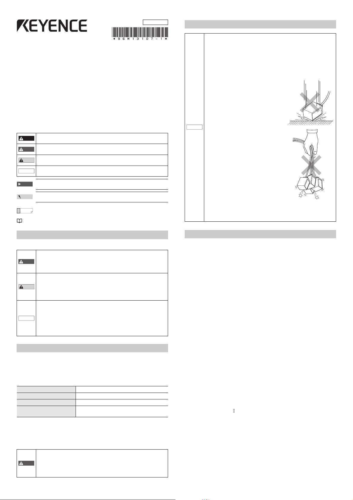
• The SR-700 Series is a precision instrument.
Do not apply shock to the instrument or drop
it. Be especially careful when transporting or
installing the unit.
NOTICE
• Do not hold the SR eries by its cable. The
units may become damaged if they strike
each other.
• Do not allow water, oil, dust, or other foreign substances to stick to the
scanner. This may cause read errors. Use a soft, dry cloth to wipe any
substances from the scanner. (Do not use a cloth dipped in alcohol or
other cleaning substance.)
Safety Information for SR-700 Series
General Precautions
• Do not use this product for the purpose to protect a human body or a part
of human body.
• This product is not intended for use as explosion-proof product. Do not
use this product in a hazardous location and/or potentially explosive
atmosphere.
• Be sure to check that the SR-700 Series performs properly before starting
the work or operation.
• If the SR-700 Series malfunctions, take adequate safety precautions to
prevent various types of damage.
• Do not use the SR-700 Series in a manner not specified herein. It may
result in fire, electric shock or malfunction.
• It should be noted that functions and performances will not be guaranteed
if the SR-700 Series is used in any way not specified or described in the
product specifications or it is modified.
• When the SR-700 Series is used in combination with other devices,
functions and performance may be degraded, depending on the operating
conditions and environment.
• If the equipment is used in a manner not specified by the manufacturer.
the protection provided by the equipment may be impaired.
Safety precautions on Laser product
The SR-700 Series ULTRA-COMPACT Code Reader uses a visible
semiconductor laser, with a wavelength of 660 nm, as a Laser pointer for
adjusting the reading position.
Laser Pointer Specifications
Wavelength 660 nm
Output 60 μW
Pulse duration 20 0μs
Laser class
(IEC60825-1:2007, FDA(CDRH) Part 1040.10*)
* The laser classification for FDA(CDRH) is implemented based on
IEC60825-1 in accordance with the requirements of Laser Notice No.50.
Follow the instructions mentioned in this manual. Otherwise, injury to the
human body (eyes and skin) may result.
• Use of controls or adjustments or performance of procedures other than
those specified herein may result in hazardous radiation exposure.
• Do not disassemble this product. The laser radiation emission from this
product is not automatically stopped when it is disassembled.
Precautions on Class 1 Laser Product
• Do not stare into the direct or specularly reflected beam.
Class 1 Laser Product
Precautions on Regulations and Standards
CE Marking
Keyence Corporation has confirmed that this product complies with the
essential requirements of the applicable EC Directive, based on the
following specifications. Be sure to consider the following specifications
when using this product in the Member State of European Union.
z EMC Directive (2004/108/EC)
• Applicable standards EMI : EN61326-1, Class A
EMS : EN61326-1
• This product is intended to be used in an industrial electromagnetic
environment.
Remarks:
These specifications do not give any guarantee that the end-product with
this product incorporated complies with the essential requirements of
EMC Directive. The manufacturer of the end-product is solely responsible
for the compliance on the end-product itself according to EMC Directive.
z Low-voltage Directive (2006/95/EC)
• Applicable Standard EN60825-1,
Class 1 Laser Product
EN62471
CSA Certificate
This product complies with the following CSA and UL standards and has
been certified by CSA.
• Applicable standards: CAN/CSA C22.2 No.61010-1
Be sure to consider the following specifications when using this product as a
product certified by CSA.
• Overvoltage category
• Use this product under pollution degree 2.
• Use this product at the altitude of 2000 m or less.
• Indoor use only.
• When using this product, use the following power supply.
•CSA or UL certified power supply that provides Class 2 output as defined
in the CEC (Canadian Electrical Code) and NFPA79 (NEC: National
Electrical Code), or
•CSA or UL certified power supply that has been evaluated as a Limited
Power Source as defined in CAN/CSA-C22.2 No. 60950-1/UL60950-1.
1
UL61010-1
E SR-700-IM
Page 2
FDA (CDRH) Regulations
1
E SR-700-IM
ULTRA-COMPACT Fixed Mount Code Reader
SR-700 Series
Instruction manual
Read this instruction manual before using the product in order to achieve
maximum performance.
Keep this instruction manual in a safe place after reading it so that it can be
used at any time.
Symbols
The following symbols alert you to important messages. Be sure to read
these messages carefully.
Important
It indicates cautions and limitations that must be followed during operation.
Point
It indicates additional information on proper operation.
Reference
It indicates tips for better understanding or useful information.
indicates the reference pages in this manual or the reference pages in separate manuals.
Safety Information for SR-700 Series
General Precautions
Safety precautions on Laser product
The SR-700 Series ULTRA-COMPACT Fixed Mount Code Reader uses a visible
semiconductor laser, with a wavelength of 660 nm, as a Laser pointer for
adjusting the reading position.
Laser Pointer Specifications
*The laser classification for FDA(CDRH) is implemented based on
IEC60825-1 in accordance with the requirements of Laser Notice No.50.
Follow the instructions mentioned in this manual. Otherwise, injury to the
human body (eyes and skin) may result.
Precautions on Proper Use
Precautions on Regulations and Standards
CE Marking
Keyence Corporation has confirmed that this product complies with the
essential requirements of the applicable EC Directive, based on the
following specifications. Be sure to consider the following specifications
when using this product in the Member State of European Union.
zEMC Directive (2004/108/EC)
Applicable standards EMI:EN61326-1, Class A
EMS:EN61326-1
Remarks:
These specifications do not give any guarantee that the end-product with
this product incorporated complies with the essential requirements of
EMC Directive. The manufacturer of the end-product is solely responsible
for the compliance on the end-product itself according to EMC Directive.
zLow-voltage Directive (2006/95/EC)
Applicable Standard EN60825-1,
Class 1 Laser Product
EN62471
CSA Certificate
This product complies with the following CSA and UL standards and has
been certified by CSA.
Applicable standards: CAN/CSA C22.2 No.61010-1
UL61010-1
Be sure to consider the following specifications when using this product as a
product certified by CSA.
Overvoltage category
Use this product under pollution degree 2.
Use this product at the altitude of 2000 m or less.
Indoor use only.
When using this product, use the following power supply.
CSA or UL certified power supply that provides Class 2 output as defined
in the CEC (Canadian Electrical Code) and NFPA79 (NEC: National
Electrical Code), or
CSA or UL certified power supply that has been evaluated as a Limited
Power Source as defined in CAN/CSA-C22.2 No. 60950-1/UL60950-1.
Either PoE or 24V power supply shall be used.
The symbol on the product means "Direct current".
It indicates a hazardous situation which, if not avoided, will result in death or
serious injury.
It indicates a hazardous situation which, if not avoided, could result in death
or serious injury.
It indicates a hazardous situation which, if not avoided, could result in minor
or moderate injury.
It indicates a situation which, if not avoided, could result in product damage
as well as property damage.
Do not use this product for the purpose to protect a human body or a part
of human body.
This product is not intended for use as explosion-proof product. Do not
use this product in a hazardous location and/or potentially explosive
atmosphere.
Be sure to check that the SR-700 Series performs properly before starting
the work or operation.
If the SR-700 Series malfunctions, take adequate safety precautions to
prevent various types of damage.
Do not use the SR-700 Series in a manner not specified herein. It may
result in fire, electric shock or malfunction.
It should be noted that functions and performances will not be guaranteed
if the SR-700 Series is used in any way not specified or described in the
product specifications or it is modified.
When the SR-700 Series is used in combination with other devices,
functions and performance may be degraded, depending on the operating
conditions and environment.
Wavelength 660 nm
Output 60 PW
Pulse duration 20 0Ps
Laser class
Class 1 Laser Product
(IEC60825-1:2007, FDA(CDRH) Part 1040.10*)
Use of controls or adjustments or performance of procedures other than
those specified herein may result in hazardous radiation exposure.
Do not disassemble this product. The laser radiation emission from this
product is not automatically stopped when it is disassembled.
Precautions on Class 1 Laser Product
Do not stare into the direct or specularly reflected beam.
96M13107
DANGER
WARNING
CAUTION
NOTICE
WARNING
CAUTION
NOTICE
WARNING
Do not use a voltage other than 5VDC with the SR Series. Doing so may
lead to damage on the unit.
When using the dedicated communication units (NX-50CL, N-R2/R4/UB/
L1, or DV-90 Series), use a power supply within the appropriate range for
each unit.
Be sure to turn the power off to devices attached to the SR Series when
you plug or unplug the cables. Failure to do so may cause damage to the
SR Series.
Do not disassemble or modify the SR Series. Doing so may lead to
damage on the unit.
Keep the cables away from high-tension cables or power sources.
Otherwise, noise could cause malfunctions or accidents.
The SR Series is a precision instrument. Do
not apply shock to the instrument or drop it.
Be especially careful when transporting or
installing the unit.
Do not hold the SR eries by its cable. The
units may become damaged if they strike
each other.
Do not allow water, oil, dust, or other foreign substances to stick to the
scanner. This may cause read errors. Use a soft, dry cloth to wipe any
substances from the scanner. (Do not use a cloth dipped in alcohol or
other cleaning substance.)
NOTICE
Main unit (SR-700HA/SR-700/SR-710)
Instruction ManualMounting bracket x 1
Insulating spacer x 2
Washer x 2
Installation screws (M3) x 2
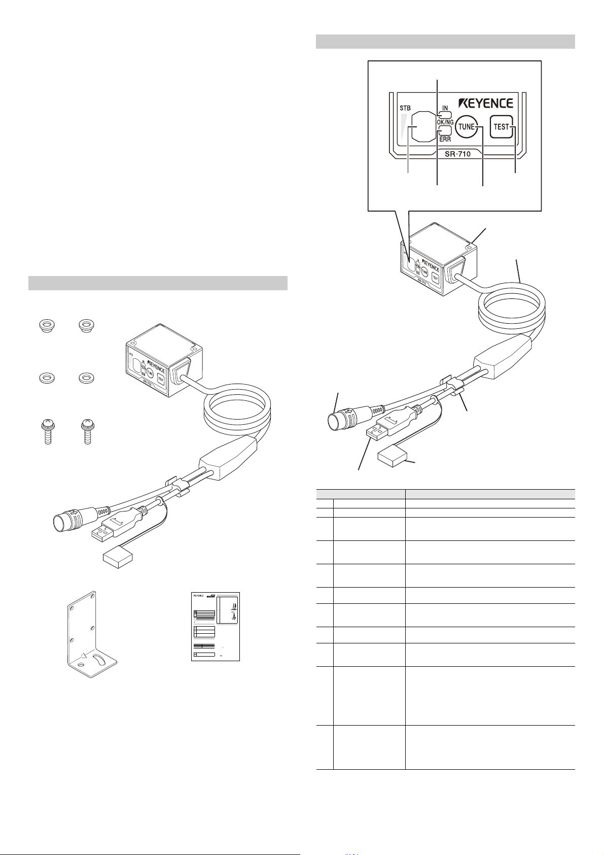
(7) Multiple LED
indicator
(9) OK/NG/ERR LED
(10) TUNE switch
(11) TEST switch
(1) Scanner
(3) Connector
(round connector)
(2) Cable
(4) USB connector
(5) USB connector cap
(8) IN LED
(6) Cable holder
This product complies with the following FDA (CDRH) regulations.
• FDA(CDRH) Part 1040.10, Class 1 Laser Product
The laser classification for FDA(CDRH) is implemented based on IEC608251 in accordance with the requirements of Laser Notice No.50.
FCC Regulations
This product complies with the following FCC EMI regulations.
• FCC Part 15 Subpart B, Class A Digital Device
IC (Industry Canada) Regulations
This product complies with the following IC EMI regulations.
• ICES-003, Class A Digital Apparatus
Radio Waves Act in South Korea
Class A Equipment
This is a class A product. In a domestic environment this product may cause
radio interference in which case the user may be required to take adequate
measures.
Note: This caution is effective for the Korean Radio Act only.
A 급 기기 ( 업무용 방송통신기자재 )
이 기기는 업무용 (A 급 ) 전자파적합기기로서 판매자 또는 사용자는 이 점을
주의하시기 바라며 , 가정외의 지역에서 사용하는 것을 목적으로 합 니다 .
Checking the Package Contents
Part Names and Functions
(1) Scanner Reads 2D codes and barcodes.
Name Function
(2) Cable Cable length is 1.8 m.
Connector
(3)
(Round connector)
(4) USB Connector
(5) USB connector cap
(6) Cable holder
(7) Multiple LED indicator
(8) IN LED
(9) OK/NG/ERR LED
(10) TUNE switch
(11) TEST switch
Connects to the power supply and communication unit
(N-R2/UB/R4/L1). The connector can be used for serial
communications with external devices.
Connects to a PC to change settings with AutoID Network
Navigator. The connector is type A. Cable length is 130 mm
from the section where the cable splits.
When the USB connector is not in use, place the cap on the
connector to prevent the entry of dust and contact with
surrounding metal objects.
When the USB connector is not in use, place the USB cable
in the cable holder so that it does not move around.
Displays the operation status including the bank number
upon successful decoding, reading stability and operation
mode.
Lights up when an input terminal is on.
(Default settings: Displays the Input terminal 1 state)
• Lights green when a OK signal is output.
• Lights orange when an NG signal is output.
• Lights red when an ERROR signal is output.
Use this switch to perform the following operations. Refer to
the user manual for more details.
• Turn on the laser pointer for reading position adjustment
• Display registered parameter banks
(Up to10 banks can be registered.)
• Start parameter tuning
• Read all of the program codes
• Reset errors
Use this switch to perform the following operations. Refer to
the user manual for more details.
• Start and stop test mode
• Run 1 reading operation
• Fix the communication settings to the default values when
sending and receiving the settings
E SR-700-IM
2
Page 3

Connection and Wiring Method
610594
21
8
1211
3
7
RP17-13PA-12PC plug (male)
Made by Hirose Electric Co., Ltd.
GND
+5V
12
+
11
5 VDC
NOTICE
Internal circuit
GND
OUT
12
+
1, 2,
5, 9
Load
* Rated load: 24VDC (30mA) or less
4.7kΩ
47kΩ
33V
RxD(RD)
RxD
RTS(RS)
RTS
TxD(SD)
TxD
SR-700 Series PC, PLC
D-sub 9-pin
(female)
#4-40 screw
Round
connector
12-pin
(female)
CTS(CS)
CTS
GND(SG)GND
+5V
+
DTR(ER)
DSR(DR)
3
4
7
8
12
11
2
7
3
8
5
4
6
Connection to the communication unit
Connect the connector to the communication
unit (N-R2/UB/R4/L1).
Refer to the communication unit instruction
manual for more details.
Input terminal 1 and Input terminal 2 wiring
These are non-voltage inputs. Connect relay contacts or NPN open collector
outputs.
• The TIMING and PRESET inputs are non-voltage inputs.
10kΩ
Internal circuit
4.7kΩ
DC5V
220Ω
IN
GND
6,10
12
With or
without
contacts
Connector pin alignment
Pin no. Wire color Signal name Description
1 Transparent OUT1
2GrayOUT2
3 Purple TxD RS-232C send Output
4 Blue CTS RS-232C send OK Input
5 Lt. blue OUT4
6 Yellow green IN2
7 Brown RxD RS-232C receive Input
8 Pink RTS RS-232C receive OK Output
9OrangeOUT3
10 Yellow IN1
11 Red 5 V 5 V Power –
12 Black GND (SG) Power GND/Signal GND –
* The shielded wire is connected to a signal ground.
Output terminal 1
(Default value:
OK output)
Output terminal 2
(Default value:
NG/ERROR output)
Output terminal 4
(Default value:
BUSY output)
Input terminal 2
(Default value:
PRESET input)
Output terminal 3
(Default value:
ERROR output)
Input terminal 1
(Default value:
TIMING input)
Signal
direction
Output
Output
Output
Input
Output
Input
• TIMING (Input terminal 1) is input to initiate the 2D code and barcode
reading.
• PRESET (Input terminal 2) is input to preset (register) the 2D code and
barcode data on the SR-700 Series.
Output terminal 1, Output terminal 2, Output terminal 3
and Output terminal 4 wiring
These are NPN open collector outputs.
• OK (Output terminal 1) is output for a successful reading when a check
against preset data is successful.
• NG/ERROR output (Output terminal 2) is output for an unsuccessful
reading when a check against preset data fails.
• ERROR (Output terminal 3) is output for an unsuccessful reading.
• BUSY (Output terminal 4) is output when preset data registration has been
completed and internal processing is taking place.
When BUSY is output, TIMING (Input terminal 1) cannot be input.
RS-232C wiring
Use the following wiring when connecting to a PC or a PLC.
It is possible to change the functions of the input terminals and output
terminals. Refer to the user's manual for making these changes.
Connecting the power
• Do not use a reverse connection for the power supply. Doing so may
damage the unit.
• Use a stable power supply that is 5 VDC +5%, -10%.
Using a power supply that exceeds this range may damage the unit.
3
E SR-700-IM
Page 4

Installing the SR-700 Series
Point
Reading distance
15°
Reading distance
20° or more
15° or more
Focal
distance
Included
installation screws
M3 x2
Mounting
bracket
Mounting
bracket
Installation
screw (M4)
Washer
Insulating
spacer
Mounting the SR-700 Series
Install the SR-700 Series as shown below to ensure reading stability.
Installation angle
The scanner of the SR-700 Series should be positioned at an angle of 15° in
relation to the 2D code or barcode surface when carrying out reading.
Do not position the scanner to face directly at 2D codes or barcodes. Doing
so may cause instability in reading due to mirror reflection.
Using the included mounting bracket
1 Attach the SR-700 Series to the mounting bracket.
Secure the mounting bracket with the included M3 screws.
2 Secure the mounting bracket to the device.
Secure the mounting bracket to the device using the installation screws,
purchased separately, with the included insulating spacers and washers.
The installation screws should be at least 3.7 mm (thickness of the
bracket, washer, etc.) + 3 mm long.
Adjusting the installation position and distance
1 Press the TUNE switch on the SR-700 Series. The laser pointer will
emit a laser beam.
Adjust the installation position and distance so that the laser pointer
intersection point and the center of the barcode line up.
The distance where the left
and right laser beams
intersect is the optimal
reading distance.
Adjust the laser pointer's
intersection point so that it
lies directly in the middle
of the 2D code or the
barcode.
Refer to the user's manual for tuning and confirming reading stability.
• The reading distance and angle differ depending on conditions such as
the size and the print quality of the 2D code or the barcode. Carry out
reading tests using the 2D code or barcode to be used and make
adjustments.
• Make sure to attach the included insulating spacers to prevent excessive
NOTICE
noise from the device.
• Reading errors may occur if the insulating spacers are not attached.
E SR-700-IM
4
Page 5

Attaching directly to the device
Point
Installation screws (M3)
NOTICE
Center of scanner
(27.8)
24.33.5
3.5
33
(36.5)
9.3
32
40
18.5
13.2
24
φ
5
Minimum bend R10
3.8
11
2-M3
Depth 4 mm
Cable length 130
Cable length 200
Cable length 1800
Thickness 13
53
21
2-(R2.65)
R1.5
R18
40°
27.5
5.3
18.5
C1
7
φ
5.3
32
24.3
0.7 0.7
3.5
2-R1.5
3.5
8-(R1.65)
4-3.3
33
60.8
1.5
0.7
6
6
90°±1.5°
18
2-M4
40°
Screw hole size
Secure the SR-700 Series with screws (M3).
The installation screws, purchased separately, should not be any longer than
the length of the plate thickness + 4 mm.
• Use insulating material when installing the SR-700 Series to prevent
excessive noise from the device.
• Reading errors may occur if the insulating material is not attached.
Mounting bracket
* An insulating sheet is affixed to the bottom surface of the mounting
bracket. Do not remove the sheet.
Dimensions
Main unit (SR-700/710/700HA)
5
E SR-700-IM
Page 6

Specifications
Copyright (c) 2014 KEYENCE CORPORATION. All rights reserved.
13107E 1084-1 96M13107 Printed in Japan
Model SR-700HA SR-700 SR-710
Typ e
Light source Visible semiconductor laser (660 nm)
Laser pointer
Light Light source High intensity red LED
Reading
Input/output
Environment
resistance
Rating
Weight Approx. 160 g (including the cable)
Output 60 μW
Pulse width 200 μs
Laser class
2D Code
Supported
code
Focal distance 38 mm 60 mm 100 mm
Minimum
resolution
Reading
distance
(typical
examples)
Reading view range
(focal distance)
Control input 2 non-voltage inputs (IN1, IN2)
Control output
RS-232C
USB Full-speed USB 2.0 interface
Enclosure rating IP65
Ambient temperature 0 to +45°C
Storage temperature -10 to +50
Relative humidity 35 to 95% RH (No condensation)
Ambient luminance
Operating environment Location without dust or corrosive gas
Vibrati on
Power supply voltage 5 VDC +5%, -10%
Current consumption 630 mA or less
Barcode *1
2D Code 0.082 mm 0.127 mm 0.19 mm
Barcode - 0.127 mm 0.127 mm
2D Code
Barcode
Communicati
on method
Transmission
speed
Synchronizati
on method
Supported
protocol
Data bit
length
Stop bit
length
Parity check None/Even/Odd
*1 Barcodes fitted into the visual field range in size can be read.
High
resolution
(IEC60825-1, FDA CDRH Part 1040.10)
GS1 DataMatrix, PDF417, Micro PDF417,
GS1 Composite (CC-A, CC-B, CC-C)
22 to 50 mm
(Cell size=
0.25 mm)
26 mm x
17 mm
4 NPN open collector outputs (OUT1 to OUT 4)
ON: Residual voltage 0.8 V or less,
OFF: leakage current 0.1 mA or less
9600, 19200, 38400, 57600, 115200 bps
No-protocol, MC Protocol, SYSWAY, KVSTUDIO
Sunlight: 10,000lx, incandescent lamp 6,000lx,
10 to 55 Hz: double amplitude 1.5 mm in the X, Y
and Z directions. 3 hours respectively.
Short-range Mid-range
Class 1
QR, MicroQR, DataMatrix,
Code 39, ITF,
2of5 (Industrial 2of5),
COOP 2of5, NW-7 (Codabar),
Code 128, GS1-128,
GS1 DataBar, Code 93,
JAN/EAN/UPC,
Trioptic Code 39
CODE39 FullASCII,
40 to 80 mm
(Cell size=
0.25 mm)
30 to 100 mm
-
(Narrow bar
width
= 0.33 mm)
42 mm x
27 mm
30 mA max. (24 V or less)
RS-232C standards
Asynchronous
7/8 bits
1/2 bits
fluorescent lamp: 2,000lx
Pharmacode
45 to 165 mm
(Cell size=
45 to 195 mm
(Narrow bar
= 0.5 mm)
C
°
0.5 mm)
70 mm x
45 mm
,
width
WARRANTIES AND DISCLAIMERS
(1) KEYENCE warrants the Products to be free of defects in materials and
workmanship for a period of one (1) year from the date of shipment. If any
models or samples were shown to Buyer, such models or samples were used
merely to illustrate the general type and quality of the Products and not to
represent that the Products would necessarily conform to said models or
samples. Any Products found to be defective must be shipped to KEYENCE
with all shipping costs paid by Buyer or offered to KEYENCE for inspection and
examination. Upon examination by KEYENCE, KEYENCE, at its sole option,
will refund the purchase price of, or repair or replace at no charge any Products
found to be defective. This warranty does not apply to any defects resulting
from any action of Buyer, including but not limited to improper installation,
improper interfacing, improper repair, unauthorized modification, misapplication
and mishandling, such as exposure to excessive current, heat, coldness,
moisture, vibration or outdoors air. Components which wear are not warranted.
(2) KEYENCE is pleased to offer suggestions on the use of its various Products.
They are only suggestions, and it is Buyer's responsibility to ascertain the
fitness of the Products for Buyer’s intended use. KEYENCE will not be
responsible for any damages that may result from the use of the Products.
(3) The Products and any samples ("Products/Samples") supplied to Buyer are not
to be used internally in humans, for human transportation, as safety devices or
fail-safe systems, unless their written specifications state otherwise. Should any
Products/Samples be used in such a manner or misused in any way,
KEYENCE assumes no responsibility, and additionally Buyer will indemnify
KEYENCE and hold KEYENCE harmless from any liability or damage
whatsoever arising out of any misuse of the Products/Samples.
(4) OTHER THAN AS STATED HEREIN, THE PRODUCTS/SAMPLES ARE
PROVIDED WITH NO OTHER WARRANTIES WHATSOEVER. ALL
EXPRESS, IMPLIED, AND STATUTORY WARRANTIES, INCLUDING,
WITHOUT LIMITATION, THE WARRANTIES OF MERCHANTABILITY,
FITNESS FOR A PARTICULAR PURPOSE, AND NON-INFRINGEMENT OF
PROPRIETARY RIGHTS, ARE EXPRESSLY DISCLAIMED.
IN NO EVENT SHALL KEYENCE AND ITS AFFILIATED ENTITIES BE
LIABLE TO ANY PERSON OR ENTITY FOR ANY DIRECT, INDIRECT,
INCIDENTAL, PUNITIVE, SPECIAL OR CONSEQUENTIAL DAMAGES
(INCLUDING, WITHOUT LIMITATION, ANY DAMAGES RESULTING FROM
LOSS OF USE, BUSINESS INTERRUPTION, LOSS OF INFORMATION,
LOSS OR INACCURACY OF DATA, LOSS OF PROFITS, LOSS OF
SAVINGS, THE COST OF PROCUREMENT OF SUBSTITUTED GOODS,
SERVICES OR TECHNOLOGIES, OR FOR ANY MATTER ARISING OUT OF
OR IN CONNECTION WITH THE USE OR INABILITY TO USE THE
PRODUCTS, EVEN IF KEYENCE OR ONE OF ITS AFFILIATED ENTITIES
WAS ADVISED OF A POSSIBLE THIRD PARTY’S CLAIM FOR DAMAGES
OR ANY OTHER CLAIM AGAINST BUYER. In some jurisdictions, some of the
foregoing warranty disclaimers or damage limitations may not apply.
BUYER'S TRANSFER OBLIGATIONS:
If the Products/Samples purchased by Buyer are to be resold or delivered to a
third party, Buyer must provide such third party with a copy of this document, all
specifications, manuals, catalogs, leaflets and written information provided to
Buyer pertaining to the Products/Samples.
E 1101-3
E SR-700-IM
6
 Loading...