

Page 1
2D Code Reader (Fixed Type)
SR-600 Series
Instruction Manual
Read this manual before use.
Keep this manual in a safe place for future reference.
Failure to follow instructions may lead to death or serious injury.
DANGER
Failure to follow instructions may lead to injury.
WARNING
96M11490
Operating Precautions
• Do not use a voltage other than 5VDC with the SR-600
Series. Doing so may lead to damage on the unit.
• When using the dedicated communication units (NX-50
Series, N-R2/R4/UB/L1, or DV-90 Series), use a power
supply within the appropriate range for each unit.
• Be sure to turn the power off to devices attached to the
SR-600 series when you plug or unplug the cables.
Failure to do so may cause damage to the SR-600 Series.
• Do not disassemble or modify the SR-600 Series. Doing
so may lead to damage on the unit.
• Keep the cables away from high-tension cables or power
sources. Otherwise, noise could cause malfunctions or
accidents.
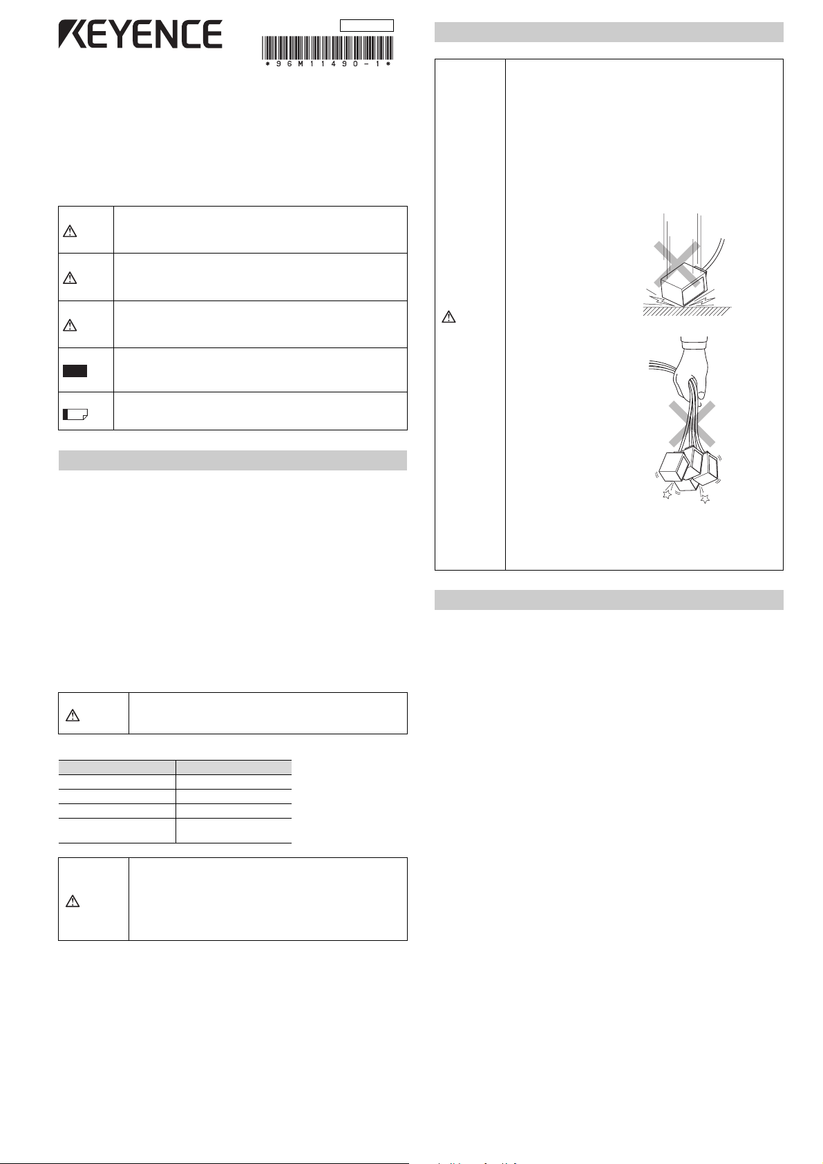
• The SR-600 Series is a
precision instrument. Do
not apply shock to the
instrument or drop it. Be
especially careful when
transporting or installing
the unit.
Failure to follow instructions may lead to product damage or
CAUTION
malfunctions.
Note
Reference
Provides additional information on proper operations that can be
easily mistaken.
Provides advanced and useful information for operation.
Safety Information for SR-600 Series
General cautions
• Take substantial safety measures to avoid any damage in the unlikely event of a
problem occurring.
• KEYENCE cannot guarantee the functionality or performance of units that have been
modified or used with specifications other than those described in this manual.
• When the SR-600 Series is used in combination with other devices, functions and
performance may be degraded, depending on the operating conditions and
surrounding environment.
• Parts of this manual may not be used or duplicated without express permission.
• The contents of his manual are subject to change without notice.
• This product is just intended to detect the object(s). Do not use this product for the
purpose to protect a human body or a part of human body.
• This product is not intended for use as explosion-proof product. Do not use this
product in hazardous location and/or potentially explosive atmosphere.
Safety precautions for laser product
The SR-600 Series uses a visible semiconductor laser, with wavelength of 660 nm, as a
target pointer for adjusting the reading position.
Use of controls or adjustments or performance of
CAUTION
Wavelength 660 nm
Pulse width 200 μs
Laser class
WARNING
procedures other than those specified herein may result in
hazardous radiation exposure.
Laser pointer
Output 90 μW
Class 1 laser product
IEC60825-1
Follow the instructions mentioned in this manual. Otherwise,
injury to the human body (eyes and skin) may result.
Precautions on class 1 laser products
• Do not stare into the beam.
• Do not disassemble this product. Laser emission from
this product is not automatically stopped when it is
disassembled.
CAUTION
• Do not hold the SR-600
Series by its cable. The
units may become
damaged if they strike
each other.
• Do not allow water, oil, dust, or other foreign substances
to stick to the scanner. This may cause read errors. Use a
soft, dry cloth to wipe any substances from the scanner.
(Do not use a cloth dipped in alcohol or other cleaning
substance.)
Regulations and Standards
UL Certifications
The SR-600 Series is an UL/C-UL Listed/Recognized product.
• File No.: E207185, Category: NRAQ/NRAQ7, Applicable standard: UL508
• File No.: E167973, Category: NWGQ2/NWGQ8, Applicable standard: UL60950-1
Be sure to follow the specification below.
• Use a power supply that provides Class 2 output defined in NEPA70
(NEC: National Electrical Code).
• Pollution degree: 2
• Overvoltage category: I
FDA (CDRH) Regulations
The SR-600 Series complies with the following FDA (CDRH) regulations.
Applicable regulations: 21 CFR Part 1040.10, Class 1 Laser Product
The classification is based on IEC60825-1 according to the Laser Notice No. 50 issued
by FDA (CDRH).
CE Marking
The SR-600 Series complies with the essential requirements of EMC Directive and Lowvoltage Directive.
The following harmonized standards are applied.
Applicable standards (EMI): EN55011, Class A
(EMS): EN61000-6-2
(LVD): EN60825-1, Class 1 Laser Product
* We conducted the test on the combination with the SR-600 series and the
communication units (N-R2/UB/R4/L1) to confirm the conformity.
EN55022, Class A
EN61000-6-1
FCC Regulations
The SR-600 Series complies with the following FCC EMI regulations.
• FCC 47 CFR Part 15, Subpart B, Class A, Digital devices
Canada IC (Industry Canada) Regulations
The SR-600 Series complies with the following IC EMI regulations.
• ICES-003, Class A, Digital apparatus
1
E SR-600-IM
Page 2
Checking the Package Contents
Part Names and Functions
Insulating spacer x 2
Washer x 2
Installation screws (M3) x 2
Main unit (SR-600/610/600HA)
Instruction ManualMounting bracket x 1
96M11490
Operating Precautions
•Do not use a voltage other than 5VDC with the SR-600
Series. Doing so may lead to damage on the unit.
2D Code Reader (Fixed Type)
•When using the dedicated communication units (NX-50
Series, N-R2/R4/UB/L1, or DV-90 Series), use a power
supply within the appropriate range for each unit.
SR-600 Series
•Be sure to turn the power off to devices attached to the
SR-600 series when you plug or unplug the cables.
Failure to do so may cause damage to the SR-600 Series.
Instruction Manual
•Do not disassemble or modify the SR-600 Series. Doing
so may lead to damage on the unit.
Read this manual before use.
•Keep the cables away from high-tension cables or power
Keep this manual in a safe place for future reference.
sources. Otherwise, noise could cause malfunctions or
accidents.
•The SR-600 Series is a
precision instrument. Do
Failure to follow instructions may lead to death or serious injury.
DANGER
not apply shock to the
instrument or drop it. Be
especially careful when
transporting or installing
Failure to follow instructions may lead to injury.
WARNING
the unit.
Failure to follow instructions may lead to product damage or
CAUTION
CAUTION
malfunctions.
•Do not hold the SR-600
Series by its cable. The
units may become
Provides additional information on proper operations that can be
Note
damaged if they strike
easily mistaken.
each other.
Provides advanced and useful information for operation.
Reference
Safety Information for SR-600 Series
General cautions
•Take substantial safety measures to avoid any damage in the unlikely event of a
problem occurring.
•Do not allow water, oil, dust, or other foreign substances
•KEYENCE cannot guarantee the functionality or performance of units that have been
to stick to the scanner. This may cause read errors. Use a
modified or used with specifications other than those described in this manual.
soft, dry cloth to wipe any substances from the scanner.
•When the SR-600 Series is used in combination with other devices, functions and
(Do not use a cloth dipped in alcohol or other cleaning
performance may be degraded, depending on the operating conditions and
substance.)
surrounding environment.
•Parts of this manual may not be used or duplicated without express permission.
•The contents of his manual are subject to change without notice.
•This product is just intended to detect the object(s). Do not use this product for the
Regulations and Standards
purpose to protect a human body or a part of human body.
•This product is not intended for use as explosion-proof product. Do not use this
UL Certifications
product in hazardous location and/or potentially explosive atmosphere.
The SR-600 Series is an UL/C-UL Listed/Recognized product.
Safety precautions for laser product
•File No.: E207185, Category: NRAQ/NRAQ7, Applicable standard: UL508
•File No.: E167973, Category: NWGQ2/NWGQ8, Applicable standard: UL60950-1
The SR-600 Series uses a visible semiconductor laser, with wavelength of 660 nm, as a
Be sure to follow the specification below.
target pointer for adjusting the reading position.
•Use a power supply that provides Class 2 output defined in NEPA70
(NEC: National Electrical Code).
Use of controls or adjustments or performance of
•Pollution degree: 2
procedures other than those specified herein may result in
CAUTION
•Overvoltage category: I
hazardous radiation exposure.
FDA (CDRH) Regulations
The SR-600 Series complies with the following FDA (CDRH) regulations.
Laser pointer
Applicable regulations: 21 CFR Part 1040.10, Class 1 Laser Product
Wavelength 660 nm
The classification is based on IEC60825-1 according to the Laser Notice No. 50 issued
Output 90 μW
by FDA (CDRH).
Pulse width 200 μs
Class 1 laser product
CE Marking
Laser class
IEC60825-1
The SR-600 Series complies with the essential requirements of EMC Directive and Lowvoltage Directive.
The following harmonized standards are applied.
Follow the instructions mentioned in this manual. Otherwise,
Applicable standards(EMI): EN55011, Class A
injury to the human body (eyes and skin) may result.
EN55022, Class A
Precautions on class 1 laser products
(EMS): EN61000-6-2
•Do not stare into the beam.
WARNING
•Do not disassemble this product. Laser emission from
this product is not automatically stopped when it is
disassembled.
EN61000-6-1
(LVD): EN60825-1, Class 1 Laser Product
* We conducted the test on the combination with the SR-600 series and the
communication units (N-R2/UB/R4/L1) to confirm the conformity.
FCC Regulations
The SR-600 Series complies with the following FCC EMI regulations.
•FCC 47 CFR Part 15, Subpart B, Class A, Digital devices
Canada IC (Industry Canada) Regulations
The SR-600 Series complies with the following IC EMI regulations.
•ICES-003, Class A, Digital apparatus
1
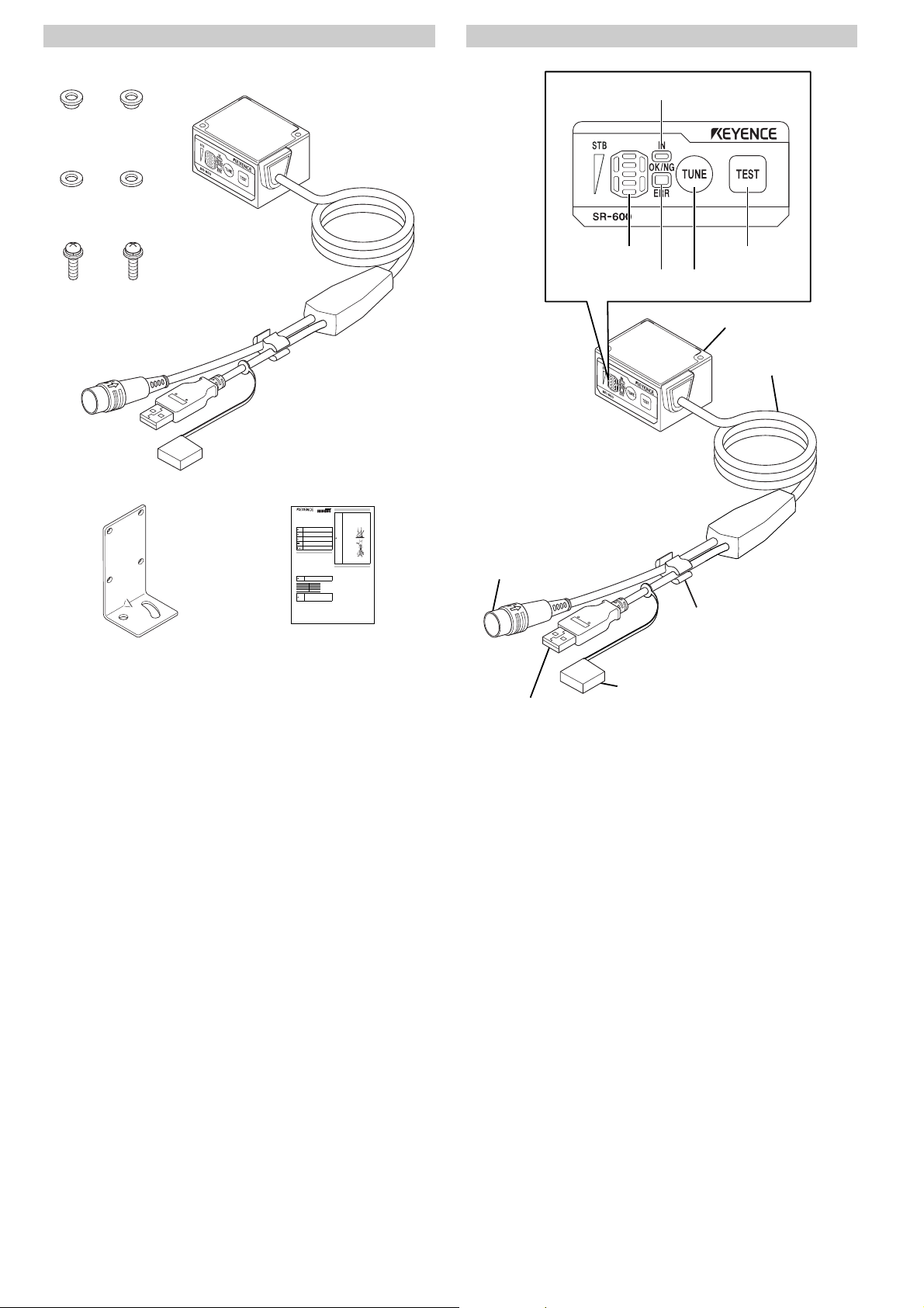
(8) IN LED
(7) Multiple LED
indicator
(9) OK/NG/ERR LED
(11) TEST switch
(10) TUNE switch
(1) Scanner
(2) Cable
(3) Connector
(round connector)
E SR-600-IM
(6) Cable holder
(5) USB connector cap
(4) USB connector
(1) Scanner: Reads 2D codes and barcodes.
(2) Cable: Cable length is 1.8 m.
(3) Connector
(Round connector):
(4) USB Connector: Connects to a PC to change settings with AutoID
(5) USB connector cap: When the USB connector is not in use, place the cap
(6) Cable holder: When the USB connector is not in use, place the
(7) Multiple LED indicator: Displays the operation status including the bank
(8) IN LED: Lights up when an input terminal is on.
(9) OK/NG/ERR LED:
(10) TUNE switch: Use this switch to perform the following operations.
(11) TEST switch: Use this switch to perform the following operations.
Connects to the power supply and communication
unit (N-R2/UB/R4/L1). The connector can be used for
serial communications with external devices.
Navigator. The connector is type A. Cable length is
130 mm from the section where the cable splits.
on the connector to prevent the entry of dust and
contact with surrounding metal objects.
USB cable in the cable holder so that it does not
move around.
number upon successful decoding, reading stability
and operation mode.
(Default settings: Displays the Input terminal 1 state)
• Lights green when a OK signal is output.
• Lights orange when an NG signal is output.
• Lights red when an ERROR signal is output.
Refer to the user manual for more details.
• Turn on the laser pointer for reading position
adjustment
• Display registered parameter banks
(Up to16 banks can be registered.)
• Start parameter tuning
• Read all of the program codes
• Reset errors
Refer to the user manual for more details.
• Start and stop test mode
• Run 1 reading operation
• Run the multi-reading mode
• Fix the communication settings to the default
values when sending and receiving the settings
E SR-600-IM
2
Page 3

Connection and Wiring Method
RP17-13PA-12PC plug (male)
Made by Hirose Electric Co., Ltd.
GND
+5V
12
+
11
5 VDC
Connection to the communication unit
Connect the connector to the communication unit
(N-R2/UB/R4/L1).
Refer to the communication unit instruction manual
for more details.
Connector pin alignment
21
610594
3
8
7
1211
Pin no. Wire color Symbol name Description
1 Transparent OUT1
2GrayOUT2
Output terminal 1
(Default value:
OK output)
Output terminal 2
(Default value:
NG/ERROR output)
3 Purple TxD RS-232C send Output
4 Blue CTS RS-232C send OK Input
5 Lt. blue OUT4
6 Yellow green IN2
Output terminal 4
(Default value:
BUSY output)
Input terminal 2
(Default value:
PRESET input)
7 Brown RxD RS-232C receive Input
8 Pink RTS RS-232C receive OK Output
9OrangeOUT3
10 Yellow IN1
Output terminal 3
(Default value:
ERROR output)
Input terminal 1
(Default value:
TIMING input)
11 Red 5 V 5 V Power –
12 Black GND (SG) Power GND/Signal GND –
* The shielded wire is connected to a signal ground.
It is possible to change the functions of the input terminals and output terminals. Refer
to the user's manual for making these changes.
Connecting the power
Signal
direction
Output
Output
Output
Input
Output
Input
Input terminal 1 and Input terminal 2 wiring
These are non-voltage inputs. Connect relay contacts or NPN open collector outputs.
• The TIMING and PRESET inputs are non-voltage inputs.
10kΩ
Internal circuit
• TIMING (Input terminal 1) is input to initiate the 2D code and barcode reading.
• PRESET (Input terminal 2) is input to preset (register) the 2D code and barcode data
on the SR-600 Series.
DC5V
4.7kΩ
220Ω
IN
GND
6,10
12
With or
without
contacts
Output terminal 1, Output terminal 2, Output terminal 3 and
Output terminal 4 wiring
These are NPN open collector outputs.
4.7kΩ
47kΩ
Internal circuit
* Rated load: 24VDC (30mA) or less
• OK (Output terminal 1) is output for a successful reading when a check against
preset data is successful.
• NG/ERROR output (Output terminal 2) is output for an unsuccessful reading when a
check against preset data fails.
• ERROR (Output terminal 3) is output for an unsuccessful reading.
• BUSY (Output terminal 4) is output when preset data registration has been
completed and internal processing is taking place.
When BUSY is output, TIMING (Input terminal 1) cannot be input.
33V
OUT
GND
1, 2,
5, 9
12
Load
+
RS-232C wiring
Use the following wiring when connecting to a PC or a PLC.
SR-600 Series DOS/V computer
TxD
CTS
RxD
RTS
+5V
3
4
7
8
12
11
Round
connector
12-pin
(male)
+
2
7
3
8
5
4
6
D-sub 9-pin
(female)
#4-40 screw
RxD(RD)
RTS(RS)
TxD(SD)
CTS(CS)
GND(SG)GND
DTR(ER)
DSR(DR)
• Do not use a reverse connection for the power supply.
Doing so may damage the unit.
CAUTION
• Use a stable power supply that is 5 VDC +5%, -10%.
Using a power supply that exceeds this range may
damage the unit.
3
E SR-600-IM
Page 4

Installing the SR-600 Series
Note
Reading distance
15°
Reading distance
20° or more
15° or more
38 mm
(SR-600HA)
60 mm
(SR-600)
100 mm
Included
installation screws
M3 x2
Mounting
bracket
Mounting
bracket
Installation
screw (M4)
Washer
Insulating
spacer
Mounting the SR-600 Series
Install the SR-600 Series as shown below to ensure reading stability.
Installation angle
The scanner of the SR-600 Series should be positioned at an angle of 15° in relation to
the 2D code or barcode surface when carrying out reading.
• Do not position the scanner to face directly at 2D codes or barcodes.
Doing so may cause instability in reading due to mirror reflection.
Using the included mounting bracket
1 Attach the SR-600 Series to the mounting bracket.
Secure the mounting bracket with the included M3 screws.
2 Secure the mounting bracket to the device.
Secure the mounting bracket to the device using the installation screws, purchased
separately, with the included insulating spacers and washers. The installation
screws should be at least 3.7 mm (thickness of the bracket, washer, etc.) + 3 mm
long.
Adjusting the installation position and distance
1 Press the TUNE switch on the SR-600 Series. The laser pointer will emit a laser
beam.
Adjust the installation position and distance so that the laser pointer intersection
point (the center point between the laser pointers for the SR-610) and the center of
the barcode line up.
For the SR-600/600HA
The distance where the left
and right laser beams
intersect is the optimal
reading distance.
Adjust the laser pointer's
intersection point so that it lies
directly in the middle of the 2D
code or the barcode.
For the SR-610
The two laser
pointers
indicate the
reading width.
Adjust the laser
pointers so that
the 2D code or
the barcode
lies directly in
the middle.
CAUTION
• Make sure to attach the included insulating spacers to
prevent excessive noise from the device.
• Reading errors may occur if the insulating spacers are not
attached.
Refer to the user's manual for tuning and confirming reading stability.
• The reading distance and angle differ depending on conditions such as the size and
the print quality of the 2D code or the barcode. Carry out reading tests using the 2D
code or barcode to be used and make adjustments.
E SR-600-IM
4
Page 5

Attaching directly to the device
Note
Installation screws (M3)
Center of scanner
(27.8)
24.33.5
3.5
33
(36.5)
9.3
32
40
18.5
13.2
24
φ
5
Minimum bend R10
3.8
11
2-M3
Depth 4 mm
Cable length 130
Cable length 200
Cable length 1800
Thickness 13
53
21
Secure the SR-600 Series with screws (M3).
The installation screws, purchased separately, should not be any
longer than the length of the plate thickness + 4 mm.
Mounting bracket
* An insulating sheet is affixed to the bottom surface of the mounting bracket. Do
not remove the sheet.
2-(R2.65)
R1.5
R18
7
C1
• Use insulating material when installing the SR-600 Series
CAUTION
to prevent excessive noise from the device.
• Reading errors may occur if the insulating material is not
attached.
Dimensions
Main unit (SR-600/610/600HA)
40°
27.5
5.3
32
3.5
1.5
90°±1.5°
6
0.7
6
3.5
33
60.8
24.3
0.7 0.7
8-(R1.65)
φ
18.5
5.3
2-R1.5
4-3.3
5
E SR-600-IM
Page 6

Specifications
Model
Ty pe
Laser pointer
Light
Supported
code
Minimum
resolution
Reading
Input/output
(typical examples)
Reading
distance
(typical
examples)
Reading view range
RS-232C
SR-600 SR-610 SR-600HA
Short-range Mid-range
Light source Visible semiconductor laser (660 nm)
Output 90μW
Pulse width 200μs
Laser class
Light source High intensity red LED
LED class Class 1 (IEC60825-1)
Barcode
2D Code
Focal distance 60 mm 100 mm 38 mm
Barcode 0.127 mm 0.127 mm
2D Code 0.127 mm 0.25 mm 0.082 mm
Reading time
DataMa trix
QR
Barcode
(focal distance)
Control input 2 non-voltage inputs (IN1, IN2)
Control output
Communication
method
Transmission
speed
Synchronization
method
Data bit
length
Stop bit
length
Parity check None/Even/Odd
USB Full-speed USB 2.0 interface
(IEC60825-1, FDA CDRH Part 1040.10)
Code 39, ITF, Industrial 2of5,
COOP 2of5, NW-7 (Codabar),
Code 128, GS1-128
(EAN-128), GS1-DataBar
(RSS), Code 93, JAN/EAN/
UPC, Trioptic Code 39
QR, MicroQR, DataMatrix, PDF417, MicroPDF,
21 ms (focal distance, QR code 21 x 21)
35 to 95 mm
(Cell size
0.339 mm)
31 to 97 mm
(Cell size
0.339 mm)
29 to 106 mm
(Narrow bar
width
0.339 mm)
42.5 mm x
27.1 mm
4 NPN open collector outputs (OUT1 to OUT4)
Residual voltage 0.8 V or less, leakage current
9600, 19200, 38400, 57600, 115200 bit/s
Class 1
MaxiCode, GS1-Composite
40 to 173 mm
(Cell size
0.508 mm)
35 to 188 mm
(Cell size
0.508 mm)
44 to 205 mm
(Narrow bar
width
0.508 mm)
70.6 mm x
45.0 mm
30 mA max. (24 V or less)
0.1 mA or less
RS-232C standards
Asynchronous
7/8 bits
1/2 bits
High
resolution
-
-
19 to 51 mm
(Cell size
0.254 mm)
17 to 54 mm
(Cell size
0.254 mm)
-
26.6 mm, x
17.0 mm
Model
Ty pe
Enclosure rating IP65
Ambient temperature
Storage temperature
Environment
resistance
Rating
* Use the Limited Power Source defined in UL/IEC60950-1 to comply with UL/
IEC60950-1.
Relative humidity 35 to 95% RH (No condensation)
Ambient luminance
Operating environment Location without dust or corrosive gas
Vibration
Power supply voltage 5 VDC +5%, -10%
Current consumption 630 mA or less
Weight Approx. 160 g (including the cable)
SR-600 SR-610 SR-600HA
C
°
°
High
resolution
C
Short-range Mid-range
0 to +45
-10 to +50
Sunlight: 10,000lx, incandescent lamp
6,000lx, fluorescent lamp: 2,000lx
10 to 55 Hz: double amplitude 1.5 mm in the
X, Y and Z directions. 3 hours respectively.
Warranty
KEYENCE products are strictly factory-inspected. However, in the event of a
failure, contact your nearest KEYENCE office with details of the failure.
1. Warranty period
The warranty period shall be for one year from the date that the product has
been delivered to the location specified by the purchaser.
2. Warranty scope
(1) If a failure attributable to KEYENCE occurs within the above mentioned
warranty period, we will repair the product, free of charge. However, the
following cases shall be excluded from the warranty scope.
• Any failure resulting from improper conditions, improper environments,
improper handling, or improper usage other than described in the
instruction manual, the user’s manual, or the specifications specifically
arranged between the purchaser and KEYENCE.
• Any failure resulting from factors other than a defect of our product,
such as the purchaser’s equipment or the design of the purchaser’s
software.
• Any failure resulting from modifications or repairs carried out by any
person other than KEYENCE staff.
• Any failure that can certainly be prevented when the expendable part(s)
is maintained or replaced correctly as described in the instruction
manual, the user’s manual, etc.
• Any failure caused by a factor that cannot be foreseen at a scientific/
technical level at the time when the product has been shipped from
KEYENCE.
• Any disaster such as fire, earthquake, and flood, or any other external
factor, such as abnormal voltage, for which we are not liable.
(2) The warranty scope is limited to the extent set forth in item (1), and
KEYENCE assumes no liability for any purchaser’s secondary damage
(damage of equipment, loss of opportunities, loss of profits, etc.) or any
other damage resulting from a failure of our product.
3. Product applicability
KEYENCE products are designed and manufactured as general-purpose
products for general industries.
Therefore, our products are not intended for the applications below and are
not applicable to them. If, however, the purchaser consults with us in advance
regarding the employment of our product, understands the specifications,
ratings, and performance of the product on their own responsibility, and takes
necessary safety measures, the product may be applied. In this case, the
warranty scope shall be the same as above.
• Facilities where the product may greatly affect human life or property,
such as nuclear power plants, aviation, railroads, ships, motor vehicles,
or medical equipment
• Public utilities such as electricity, gas, or water services
• Usage outdoors, under similar conditions or in similar environments
E SR-600-IM
Copyright (c) 2010 KEYENCE CORPORATION. All rights reserved.
11490E 1110-1 96M11490 Printed in Japan
6
 Loading...