

Page 1
Danger
Caution
NOTE
Reference
Danger
96M12525
■ Environment of use
Safety Light Curtain
SL-VHS Series
Instruction Manual
Introduction
This instruction manual describes handling, operation, and precautionary information for the SL-VHS
Series Safety Light Curtain ("SL-VHS").
Read this instruction manual thoroughly before operating the SL-VHS in order to understand the
device features, and keep this instruction manual readily available for reference. Ensure that the end
user of this product receives this manual.
Safety headings
This instruction manual uses the following headings to display important safety information. Strict
adherence to the instructions next to these heading is required at all times.
Danger
■ Tar get m ach ine
Danger
■ Installation
• Do not use the SL-VHS in an environment (temperature, humidity, interfering light, etc.)
that does not conform to the specifications contained in this instruction manual.
• Do not use wireless devices such as cellular phones or transceivers in the vicinity of the
SL-VHS.
• The SL-VHS is not designed to be explosion-proof. Never use it in the presence of flammable or explosive gases or elements.
• Do not use the SL-VHS in the presence of substances, such as heavy smoke, particulate
matter, or corrosive chemical agents, that may induce deterioration in product quality.
Install the SL-VHS in such a way so that no direct or indirect light from inverter-type fluores-
•
cent lights (rapid-start type lights, high-frequency operation type lights, etc.) shine on the
device.
• Be sure to absolutely confirm that there is nobody in the hazardous zone, before the override function is activated. Failure to follow this warning results in a significant harm to the
machine operators, including serious injury or death.
•
The SL-VHS has not undergone the model certification examination in accordance with Article
44-2 of the Japanese Industrial Safety and Health Law. The SL-VHS, therefore, cannot be used
in Japan as a “Safety Device for Press and Shearing machines” as established in Article 42 of
that law.
•
The machine on which the SL-VHS is to be ins talled must be susceptible to an emergency stop at all
operating points during its operation cycle. Do not us e the SL-VHS for machines with irregular stop
times.
• Do not use the SL-VHS for power presses equipped with full-revolution clutches.
• The SL-VHS cannot be used as a PSDI because it does not fulfill the requirements of
OSHA 1910.217(h). Refer to OSHA 1910.217 for the PSDI mode.
Do not use the SL-VHS to control (stop forward motion, etc.) trains, cars and other transportation
•
vehicles, aircraft, equipment for use in space, medical devices, or nuclear power generation systems.
•
The SL-VHS is designed to protect the people or objects going into/approaching det ection zone
against machine’s hazard or hazardous zone. It cannot provide protection agai nst objects or materials that are expelled from the machine’s hazard or hazardous zone, so you must establish additional
safety measures such as installing safeguards when there is the possibility of such projectiles.
Failure to follow the instruction results in a significant harm to the machine operators
including serious injury or death.
Failure to follow the instruction may result in damage to the SL-VHS or to the machine on
which it is installed.
Provides additional information for proper operation.
Provides advanced and useful information for operation.
Safety Precautions
General precautions
• You must verify that the SL-VHS is operating correctly in terms of functionality and performance
before the start of machine and the operation of the SL-VHS.
• KEYENCE does not guarantee the function or performance of the SL-VHS if it is used in a manner that differs
from the SL-VHS specifications contained in this instruction manual or if the SL-VHS is modified by the customer.
• When using the SL-VHS to protect machine operators against a hazard or hazardous zone or using the SL-VHS
as a safety component for any purpose, always follow the applicable requirements of the laws, rules, regulations and standards in the country or region where the SL-VHS is used. For such regulations, you should contact directly to the regulatory agency responsible for occupational safety and health in your country or region.
• Depending on the type of machine on which the SL-VHS is to be installed, there may be special
safety regulations related to the use, installation, maintenance, and operation of the safety component. In such a case, you must fulfill such safety regulations. The responsible personnel must install
the SL-VHS in strict compliance with such safety regulations.
• The responsible personnel must do the training to the assigned personnel for the correct use, installation,
maintenance, and operation of the SL-VHS. "Machine operators" refers to personnel who have received
appropriate training from the responsible personnel and are qualified to operate the machine correctly.
• Machine operators must have specialized training for the SL-VHS, and they must understand and
fulfill the safety regulations in the country or region in which they are using the SL-VHS.
• When the SL-VHS fails to operate, machine operators must immediately stop the use of the
machine and the SL-VHS and report this fact to the responsible personnel.
• The SL-VHS is designed with the assumption that it would be correctly installed in accordance with
the installation procedures described in this instruction manual and correctly operated according to
the instructions in this instruction manual. You must perform an appropriate installation of the SL-VHS
after performing a sufficient risk assessment for the target machine.
• The SL-VHS should be processed as an industrial waste product when being disposed.
Precaution on use
■ Operators
• In order to operate the SL-VHS correctly, the responsible personnel and/or machine
operators must fulfill all of the procedures described in this instruction manual.
• No person other than the responsible personnel should be allowed to install or test the
SL-VHS.
• When performing electrical wiring, always fulfill the electrical standards and regulations for
the country or region in which the SL-VHS is used.
Danger
• The SL-VHS must be installed only after ensuring the minimum safety distance between
the SL-VHS and the hazardous zone or hazard as established by the applicable regulations in the country or region in which the SL-VHS is used. (e.g. EN999 (ISO 13855) in EU
countries)
• Choose locations for the installation of the SL-VHS transmitters and receivers so that they
are not subject to the effects of light reflected from glossy surfaces in the area.
• Correct operation and detection is not possible if the receiver has a different number of
beam axes from that of the transmitter. You must verify that the number of beam axes is
the same between the transmitter and the receiver when installing the SL-VHS.
Correct operation and detection is not possible if the receiver has a different beam axis spacing
•
(detection capab ility) from that of the transmi tter. You must verify that the beam axis spacing (detection capability) is the same between the transmitter and the receiver when installing the SL-VHS.
•
The SL-VHS must be installed so that the machine operator is able to go into or approach the hazardous
zone or hazards only by passing thro ugh the detection zone of the SL-VHS. Strictly avoid installa tion that
allows the machine operator or a par t of the machine operator's body to go int o or approach the hazardous zone or hazards without passi ng through the detection zone of the SL-VHS or to remai n in a position
between the detection zone of the SL-VHS and the haz ardous zone or hazard. In case where you install
the SL-VHS units in series (ser ies connection), you always must check the installation ca refully whether
you follow this warning, especially after in stallation and maintenance.
• You must always perform the pre-check tests after installing the SL-VHS in accordance
with the pre-check test procedures, such as items specified in this instruction manual, in
order to verify that the test pieces can be detected in all of the detection zones.
• Muting is a function to allow a temporary automatic suspension of the SL-VHS safety functions while the SL-VHS is receiving a signal from one or more muting devices (such as
sensors or switches). Therefore, additional safety measures are required for the machine
on which the SL-VHS is installed in order to ensure safety while the muting is activated.
• Muting devices, the installation of those devices and the procedure to activate the muting
function must fulfill the conditions specified in this instruction manual and the requirements of the laws, rules, regulations and standards in the country or region in which the
SL-VHS and those devices are used. Failure to follow this warning may result in significant
harm to the machine operators, including serious injury or death.
• When you install muting devices (such as sensors or switches) for muting, the following
conditions must be fulfilled.
(1) Muting devices must be installed so that the muting cannot be activated if the
hazardous zone of the machine is in an unsafe condition or cycle.
(2) Muting devices must be installed so that the muting cannot be activated even if the
personnel is accidentally approaching the detection zone of the SL-VHS.
The muting device must be installed such that only responsible personnel have access to that
•
device to change its installation or orientation. Special tools must be required to ensure that
only responsible personnel are capable of installation, orientation or change of muting device.
•
Only the responsible personnel may be allowed to install or wire the devices to activate the muting function.
• The installation of muting lamp may be required by the laws, rules, regulations, and standards in the country or region in which the SL-VHS is used if you apply the muting function. It depends on the machine application and/or the result of your risk assessment. If it
is necessary for you to provide the muting lamp, you must fulfill the requirements because
you are fully responsible for installation of muting lamp.
The override is a function to allow a te mporary manual suspension of t he safety functions of
•
the SL-VHS. Therefore, additional safety measures are required for the whole machine system on which the SL-VHS is instal led in order to ensure safety while the override is activated.
• The override devices, the installation of those devices and the procedures to activate the
override must fulfill the conditions specified in this manual as well as the requirements of
the laws, rules, regulations and standards in the country or region in which the SL-VHS
and those devices are used. Failure to follow this warning may result in significant harm to
the machine operators, including serious injury or death.
The override devices, which are used for activation of override, must be manual operating
•
device. When installing the devices to activate the override, thos e devices must be installed
so that the whole hazardous zone can be checked by the respons ible personnel and so that
it is not possible for machine operators to operate those devices in the hazardo us zone.
•
The installation of the indicati on for override may be required by the laws, rules, regulations,
and standards in the country or region in which the SL -VHS is used if you apply the override function. It depends o n the machine application and/or the result of your risk asses sment. If it is necessary for you to provide the indication for override, you must fulfill the
requirements because you are fully responsible for installation of t he indication for override.
1
SL-VHS-IM-E
Page 2
•
Danger
SL-VHS transmitter x1
SL-VHS receiver x1
Instruction Manual (this document) x1
Test piece x1
(Test piece with diameter of 25 mm and length of 200 mm)
Ferrite core x1
NOTE
5.8
36.1
14.3
φ
8-wire shielded cable
Brown and blue: AWG24 (nominal cross-sectional area of 0.22 mm2)
Others: AWG26 (nominal cross-sectional area of 0.14 mm
2
)
(Transmitter/receiver set)
(Transmitter/receiver set)
M14 connector, male*
* The simple function type has the M12 male connector.
(Transmitter/receiver set)
M14 connector, male
*2
M14 connector, female
*1
*1 The simple function type has the M12 female connector.
*2 The simple function type has the M12 male connector.
(Transmitter/receiver set)
M14 connector, female*
Brown and blue: AWG24 (nominal cross-sectional area of 0.22 mm2)
Others: AWG26 (nominal cross-sectional area of 0.14 mm
2
)
* The simple function type has the M12 female connector.
5.8
φ
(Transmitter/receiver set)
The customer is fully responsible for complying with the requ irements for the muting and/or
override. Those who use muting and/or override must fulfill all of the requirements related
to muting and/or override. KEYENCE accepts NO responsibility or NO liability for any damage or any injury due to the unauthorized inst allation, usage or maintenance, which are not
specified in this instruction manual, and/or due to noncompliance with the laws, rules, regulations and standards in the country or regi on in which the SL-VHS is used.
• Securely tighten mounting brackets and cable connectors used for the installation of the
SL-VHS in accordance with the torque values specified in this instruction manual.
■ Circuit design and wiring
• Always turn off the power to the SL-VHS when performing electrical wiring.
• You must fulfill the electrical standards and regulations in the country or region in which
the SL-VHS is being used when you perform the electrical wiring.
• To avoid the risk of electric shock, do not connect any of the SL-VHS inputs to DC power
sources outside of the range of 24 VDC + 10 % or to any AC power source.
• To avoid the risk of electric shock, be sure that the hazardous voltage is isolated from all
wiring of the SL-VHS with reinforced insulation or double insulation.
• In order to fulfill the requirements in IEC61496-1, UL61496-1, EN61496-1 and UL508,
power supply for the SL-VHS must fulfill the conditions listed below.
A rated output voltage of 24 VDC (SELV, Overvoltage Category II) within +10 % and -20 %.
(a)
(b) Double insulation or reinforced insulation between the primary and secondary circuits.
(c) Output holding time of 20 ms or more.
(d)
A power supply must fulfill the requirements of the electrical safety and electromagnetic
compatibility (EMC) regulations or standards in all countries and/or regions where the SL-VHS is
used.
(e) A secondary circuit of power supply (output) must fulfill the requirements for Class 2
Circuits or Limited Voltage/Current Circuits specified in UL508, if the SL-VHS is used
in the United States or Canada.
• Do not install the electric wiring of the SL-VHS together with or in parallel with high-voltage
electrical or power lines.
•
Both OSSD outputs provided on the SL-VHS must be used to establish a safety-related
machine control system. Establishing a safety-related machin e control system with just one
of the OSSD outputs cannot stop the machine due to an OSSD output malfunction and may
result in significant harm to the machine operat ors, including serious injury or death.
•
When using a PNP output type cable, do not cause short-circuit between the OSSD and +24 V.
Otherwise, the OSSDs keep staying at the ON-state and it causes a dangero us situation.
•
When using a PNP output type cable, be sure to connect the load between the OSSD and 0 V to
avoid a dangerous situation. If the load is incorrectly connected between the OSSD and +24 V,
the logic of the OSSD operation will be reversed and the OSSD will change to an ON state when
the SL-VHS detects the interruption in the detection zone. This is a dangerous situation.
•
When using NPN output type cables, do not cause short-circuit between the OSSD and 0 V.
Otherwise, the OSSDs keep staying at the ON-state and it causes a dangerous situation.
•
When using an NPN output type cable, be sure to connect the load between the OSSD and +24
V to avoid a dangerous situation. If the load is incorrectly connected between the OSSD and 0V,
the logic of the OSSD operation will be reversed and the OSSD will change to an ON state when
the SL-VHS detects the interruption in the detection zone. This is a dangerous situation.
•
In case of wiring, regardless of P NP or NPN output type cables, you must fulfill the requirements of
Clause 9.4.3 in IEC60204-1: 2005 in order for the protection against maloperation due to ear th fault.
• The Alert output, AUX output, Clear/Blocked Output, and state information output are not
allowed to be used as safety outputs for safety-related machine control systems. Usage of
these functions as safety outputs may result in a significant harm to the machine operators, including serious injury or death.
The wait input is not allowed to be connected to the output from any components co mprising a part of
•
the safety-related machine control system. If the wait input is connect ed to the output of a safety component it may result in a significant harm to the mach ine operators, including serious injury or death.
• The transmitter and receiver cables must be within the lengths specified in this instruction
manual. Usage of cables longer than the specified length may cause the improper operation of safety functions and may cause a dangerous situation.
Testing and maintenance
• You must always perform the pre-check test in accordance with the pre-check test procedures,
after maintenance, adjustment or alignment of the target machine or the SL-VHS and before the
machine startup.
• If the SL-VHS does not operate properly when you perform pre-check test in accordance with the
pre-check test procedures specified in this instruction manual, do not operate the machine.
• You must periodically examine the machine to verify that all brakes, other stop mechanisms, and
control devices operate reliably and correctly in addition to checking the SL-VHS.
• The responsible personnel must perform maintenance procedures as specified in this instruction
manual at least once every six months to ensure safety to the machine and SL-VHS.
Standards and regulations
1 The SL-VHS is a safety component as established by the European Union's Machinery Directive
(2006/42/EC) Annex IV Clause B.
The SL-VHS complies with the following EU Directives and EN Standards and has been certified
by TÜV SÜD Product Service GmbH.
EU Directives
• Machinery Directive (2006/42/EC)
• EMC Directive (2004/108/EC)
EN Standards
• EN61496-1 Type 4 ESPE
• EN61496-2 Type 4 AOPD
• EN55011 ClassA
• EN50178
• EN61508, Part 1 to 4 SIL3
• EN62061 SIL3
• EN ISO13849-1 Category 4, PLe
2 The SL-VHS complies with the following UL (Underwriters Laboratories Inc.) and IEC standards
and has been certified by UL. (CCN :NIPF/NIPF7)
• UL61496-1 Type 4 ESPE
• UL61496-2 Type 4 AOPD
• UL508
• UL1998
The SL-VHS also complies with the following regulations.
• FCC Part 15B Class A Digital Device
• ICES-003 Class A Digital Apparatus
3 The SL-VHS has not undergone the model certification examination in accordance with Article 44-
2 of the Japanese Industrial Safety and Health Law. The SL-VHS, therefore, cannot be used in
Japan as a “Safety Device for Press and Shearing machines” as established in Article 42 of that
law.
The SL-VHS has been designed in consideration of the following standards and regulations. For details
4
regarding the following standards, contact the third-party certification organization, such as UL or TÜV.
Corresponding standards
• EN60204-1
• EN415-4
•EN692
•EN693
• OSHA 29 CFR 1910.212
• OSHA 29 CFR 1910.217
• ANSI B11.1 - B.11.19
• ANSI/RIA R15.06 - 1999
• SEMI S2
• "Guidelines for Comprehensive Safety Standards of Machinery", July 31, 2007, number
0731001 issued by Ministry of Health, Labor, and Welfare in Japan.
Checking the Package Contents
Cables
• There are two types of cable: simple function type and multi-function type. The type of cable used deter mines
the function that can be used. (The number of conductors is different from each other.) Therefore, the two types
of cables cannot be mixed at the same time. Make sure to use the appropriate type of cable for your application.
• Cables with different output types cannot be combined. Be sure to match the PNP or NPN output type
especially when using the unit connection cable (for extension).
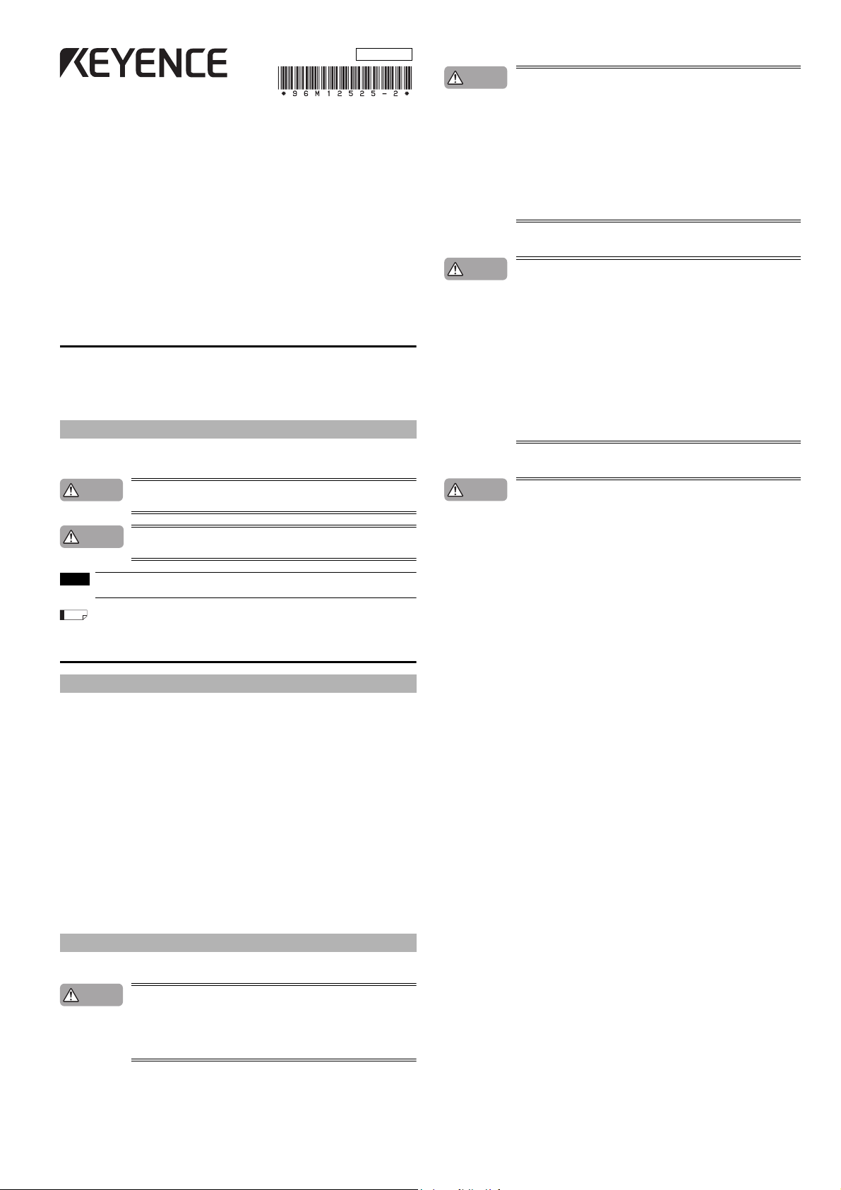
■ Unit connection cable
Shape Typ e Model
SL-VP7P
SL-VP15P 15 m
Simple
function
SL-VP7N
SL-VP15N 15 m
SL-VP7PM
SL-VP15PM 15 m
Multifunction
SL-VP7NM
SL-VP15NM 15 m
Output type
PNP
NPN
PNP
NPN
■ Unit connection cable (for extension use)
Used together with the junction cable or extension cable.
Shape Typ e Model
Simple
φ
5.8
45
function
φ
17
Multifunction
SL-VPC03P
SL-VPC5P 5 m
SL-VPC10P 10 m
SL-VPC03N
SL-VPC5N 5 m
SL-VPC03PM
SL-VPC5PM 5 m
SL-VPC10PM 10 m
SL-VPC03NM
SL-VPC5NM 5 m
Output type
PNP
NPN
PNP
NPN
■ Junction cable
Shape Typ e Model
φ
44
φ
17
5.8
45
φ
17
SL-VCC10P PNP 10 m
Simple
function
SL-VCC10N NPN 10 m
SL-VCC10PM PNP 10 m
Multifunction
SL-VCC10NM NPN 10 m
Output type
■ Extension cable
Shape Typ e Model
φ
44
φ
17
5.8
SL-VC5P
SL-VC10P 10 m
Simple
function
SL-VC5N
SL-VC10N 10 m
SL-VC5PM
SL-VC10PM 10 m
Multifunction
SL-VC5NM
SL-VC10NM 10 m
Output type
PNP
NPN
PNP
NPN
Series connection cable
Shape Model Le ngth
SL-VS0 0.08 m
SL-VS01 0.15 m
SL-VS05 0.5 m
SL-VS1 1 m
SL-VS3 3 m
SL-VS10 10 m
Length
7 m
7 m
7 m
7 m
Length
0.3 m
0.3 m
0.3 m
0.3 m
Length
Length
5 m
5 m
5 m
5 m
SL-VHS-IM-E
2
Page 3
Cable specification
Danger
2. Connector
1. Cable insulation
NOTE
Reference
6
10
11 12
9
8
7
12
3
4
5
5
837
6
1
2
4
Simple-function cable male pin assignment Multi-function cable male pin assignment
grey
M2.6
screw
black
M2.6
screw
g
Push the cable
into the groove.
Caution
Within 200 mm
Ferrite core
(diameter: 18.5 mm, length: 34 mm)
Unit connection cable
Transmitter
Attach to the transmitter
SL-VHS main unit
ReceiverTransmitter
(1) Cable length
When using the unit connection cable, junction cable, and extension cable together, the sum of the
length for all type of cables must be 30 m or less. This limitation is applicable to each the transmitter
and receiver respectively. Since up to 3 SL-VHS units (230 beam axes) can be connected in series,
up to 2 sets of series connection cables are required. Two sets of the SL-VS10 (cable length: 10 m)
cables can be used. In this case, the sum of the length of all type of cables, including the series
connection cable, must be 50 m or less. This limitation is also applicable to each transmitter and
receiver respectively.
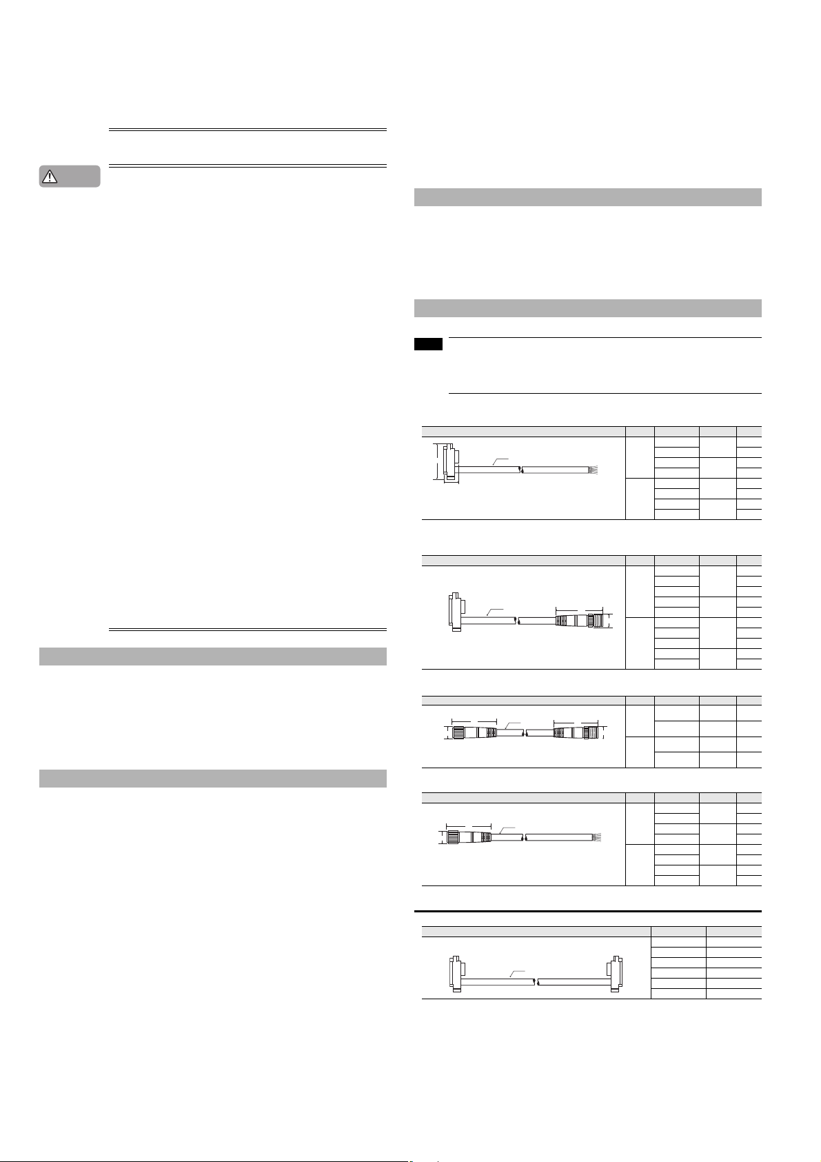
Cable connection
1
The unit connection cable for transmitter (cable insulation is grey) must be connected to the transmitter as shown below. Similarly, the unit connection cable for receiver (cable insulation is black) must be connected to the receiver as shown below.
Recommended tightening torque : 0.3 N·m
Minimum cable bending radius : 5 mm
Transmitter Receiver
(2) Minimum cable bending radius : 5 mm
(3) Identification of connector cables
Connector pin assignment
■ Simple function type
Pin No. Wire color Assigned function Pin No. Wire color Assigned function
■ Multi-function type
Pin No. Wire color Assigned function Pin No. Wire color Assigned function
10 Grey/Black State information output 2 10
11 Pink/Black Alert output 11 Light blue Muting input 1
12
• Cables must be within the lengths specified. Failure to follow this specification may cause
improper operation of safety function, and may cause dangerous situation.
•
The series connection cable cannot be cut or extended. If the cable is cut or extended, safety
features may not operate properly. Do not allow this to happen as it is extremely dangerous.
Cables can be identified by the colors of their connectors and their cable insulation.
1. Cable Insulation colors
Cables for Transmitter : Cable insulation in grey
Cables for Receiver : Cable insulation in black
2. Connector colors
PNP output type cables : Black connectors
NPN output type cables : Grey connectors
Series connection cables : Black connectors
The PNP output type cable and the NPN output type cable cannot be used together at the same time.
Use only one of these types according to the operation condition.
Be sure to connect the unit connection cable for receiver to the SL-VHS receiver and the unit connection cable for transmitter to the SL-VHS transmitter.
Transmitter Receiver
1PinkInterlock mode selection input 1WhiteOSSD 2
2Brown+24 V 2Brown+24 V
3VioletWait i nput 3BlackOSSD 1
4GreenNot used 4YellowRESET input
5 Orange Communication cable 1 (RS485_+) 5OrangeCommunication cable 1 (RS485_+)
Orange/
6
Communication cable 2 (RS 485_-) 6
Black
Orange/
Communication cable 2 (RS485_-)
Black
7Blue0 V 7Blue0 V
8RedAUX (auxiliary) output 8RedEDM input
9GreyState information output 1 9Red/BlackOverride input
Ye l l o w /
Muting lamp output
Black
White/
Clear/Blocked Output 12
Black
• The ON/OFF state of the state information output 1 indicates if the SL-VHS is in the lockout
condition.
• The ON/OFF state of the state information output 2 indicates if the SL-VHS is in the muting
condition.
• The pin assignment of the unit connection cable (for extension) is as follows.
Light blue/
Black
Muting input 2
Push the cable
roove.
into the
• Do not remove the grey gasket installed on the connector. This gasket is necessary to fulfill the requirement of IP65.
Connect the unit connection cable to the conn ector receptacle on the lower part of the SL-VHS.
•
Removing the connector cover on the upper part of th e SL-VHS and connecting the unit connection cable may result in an SL-VHS failure.
2 One ferrite core must be put on the unit connection cable for the transmitter.
Part Description
Beam center-line mark
1
*
Top
Detection
SL-V08HS
surface
ø25 (0.98")
Bottom
*1 The side where the connector cover has already been installed at shipment is the top side.
Beam center-line : An optical path joining the optical center of the emitting element on the transmit-
Detection height : The height from the top beam center-line to the bottom beam center-line (length).
Protection height : An object approaching the detection zone from the top of the detection height is first
Protection height = "Detection height" + 2 x "the specified detection capability"–"beam axis diameter".
*
Refer to the following diagram for an explanation of beam center-line, detection height and protection height.
Detection zone : The zone in which the specified detection capability can be detected. The
Protection zone : The square area formed with the protection height and the operating distance,
ter to the optical center of the corresponding receiving element on the receiver.
the SL-VHS must be installed so that the beam center-line mark on the transmitter and that on the receiver face one another and are located at the same height.
detected at point A, which is the distance of the detection capability from the top of the
detection height. The equivalent position on the bottom is called point B. The height from
the top edge of the specified detection capability that exists at point A to the bottom edge
of the specified detection capability that exists at point B is called a "protection height".
The following calculation formula can be defined:
Beam center-line mark
detection zone of the SL-VHS indicates a square area formed with the detection
height and the operating distance. When a part or whole of the specified detection capability is present in this area, the light of the SL-VHS is blocked, and then
the OSSD goes to OFF state.
which is broader than the detection zone. When a whole of the specified detection capability is present in this area, the light of the SL-VHS is blocked, and then
the OSSD goes to OFF state.
(upper)
Connector cover
LEVEL
5
Installation reference mark
4
3
2
Indicators
1
WAIT
FUNCTION
OSSD
INTER
Installation reference mark
LOCK
Connector receptacle
Beam center-line mark
(lower)
Beam center-line
height
a: Beam axis spacing
b: Beam axis diameter
c: Detection capability
LEVEL
5
4
3
2
SL-V08HS
Detection
1
surface
MUTE1
MUTE2
ø25 (0.98")
OSSD
INTER
LOCK
Specified detection capability (position A)
b
a
c
Specified detection capability (position B)
Protection heightDetection
3
SL-VHS-IM-E
Page 4

* Refer to the following diagram for detection zone and protection zone.
Protection
height
Specified detection capability
Protection zone
Operating distance
Detection zone
Detection
height
Mirror surface
X
Y
Transmitter
Receiver
External
device
Main
circuit
+24 V
0 V
10
OSSD
Ω
10 Ω
External
device
Main
circuit
+24 V
0 V
OSSD
Output
Main
circuit
+24 V
0 V
OSSD PNP output circuit OSSD NPN output circuit
Input circuit Output circuit
Receiver
Main
circuit
Blue
Brown
Yel l o w (reset input)
0 V
+24 V
Receiver
Main
circuit
Blue
Brown
Yel l o w (reset input)
0 V
+24 V
Common for a PNP/NPN output type cable
When using a PNP output type cable When using an NPN output type cable
When using a PNP output type cable When using an NPN output type cable
0 V
+24 V
Red (EDM input)
Brown
Blue
Receiver
Main
circuit
Input device
Brown
Red (AUX output)
Blue
Transmitter
Main
circuit
0 V
+24 V
When using a PNP output type cable When using an NPN output type cable
Light blue
Brown
Blue
Light blue/
Black
Receiver
(Muting input 2)
(Muting input 1)
Muting device 1
Muting device 2
Short-circuit current: 2.5 mA
Main
circuit
0 V
+24 V
Brown
Blue
Light blue
Light blue/Black
(Muting input 2)
(Muting input 1)
Receiver
Muting device 1
Muting device 2
Short-circuit current: 2.5 mA
Main
circuit
0 V
+24 V
When using a PNP output type cable When using an NPN output type cable
Yel l o w/Black
Muting
lamp
Brown
Blue
Monitor circuit
Main
circuit
Receiver
0 V
+24 V
Common for a PNP/NPN output type cable
When using a PNP output type cable When using an NPN output type cable
■ Wiring unless EDM function is applied
Installation measures against glossy surface
When determining a specific installation distance, refer to the following values including the installation tolerance.
Transmitter
o
5
Mirror surface
X
Receiver
Y
Operating distance “X” Minimum insta llation distance “Y”
Less than 3 m 0.13 m
3 m or more X/2 x tan5 ° = 0.0437 X
OSSD circuit Diagram
■ Wiring for muting device
■ Wiring for muting lamp
Transmitter
Main
circuit
Receiver
Main
circuit
Brown
Red (AUX output)
Blue
Brown
Red (EDM input)
Blue
+24 V
Input device
0 V
+24 V
0 V
+24 V
Main
circuit
Input
0 V
Wiring and Function
■ Wiring for interlock selection input
Brown
Transmitter
Main
circuit
Pink (interlock mode selection input)
Blue
+24 V
0 V
■ Wiring for Override function
Short-circuit current: 2.5 mA
Brown
Receiver
Yel l o w
Main
(Reset input)
circuit
Red/Black
(Override input)
Blue
+24 V
0 V
Receiver
Main
circuit
Brown
Yel l o w
(Reset input)
(Override input)
Red/Black
Blue
Short-circuit current: 2.5 mA
+24 V
0 V
■ Wiring for EDM function
Receiver
Main
circuit
SL-VHS-IM-E
Brown
Red
Blue
Device 1
Device 2
Short-circuit
current: 10mA
+24 V
0 V
Receiver
Main
circuit
Brown
Red
Blue
Short-circuit
current: 10mA
Device 1
Device 2
+24 V
0 V
4
Page 5

Example for Wiring
Caution
k
k
Use PNP output type for P1 and P2.
S1
S2
S3
K1
K2
K2 K1
L1
P 1
P 2
K3
K2K1
M
IN
PLC
OUT
Cable insulation: Black
Cable insulation: Grey
Transmitter
Receiver
(Not used) Green
(Interlock mode selection input) Pink
(+24 V) Brown
(+24 V) Brown
(OSSD2) White
(OSSD1) Black
(Reset input) Yellow
(EDM input) Red
(Override input) Red/black
(Muting lamp output) Yellow/black
(Muting input 1) Light blue
(Muting input 2) Light blue/black
(Wait input) Violet
(AUX output) Red
(State information output 1) Grey
(State information output 2) Grey/black
(Alert output) Pink/black
(Clear/Blocked output) White/black
(0 V) Blue
(0 V) Blue
Shield
Shield
Brown
Brown
Blue
Blue
Black
Black
Orange/black
(Communication cable 2)
Orange
(Communication cable 1)
Use NPN output type for P1 and P2.
• The shielding wire of the PNP output type cable is connected to 0 V line in the SL-VHS.
Do not connect the shielding wire to +24 V line.
• The shielding wire of the NPN output type cable is connected to +24 V line in the SL-VHS.
Do not connect the shielding wire to 0 V line.
• When not using a non safety-related output, insulate the wires.
■ When using a simple function type cable (When not using the EDM function)
Meaning of symbols
K1, K2: External device (Safety relay unit, etc.)
PNP output type cable
Transmitter
Cable insulation: Grey
Shield
(0 V) Blue
(Not used) Green
(Wait input) Violet
(AUX output) Red
(Interlock mode selection input) Pink
NPN output type cable
Transmitter
Cable insulation: Grey
Orange
(Communication cable 1)
Orange/black
(Communication cable 2)
(+24 V) Brown
Orange
(Communication cable 1)
Orange/black
(Communication cable 2)
(+24 V) Brown
(OSSD2) White
K2
Receiver
Cable insulation: Blac
(OSSD1) Black
(EDM input) Red
(Reset input) Yellow
K1
Receiver
Cable insulation: Blac
(0 V) Blue
Shield
■ When using a multi-function type cable (When using the EDM function)
Meaning of symbols
K1, K2: External device (Safety relay unit, magnet contactor, etc.)
K3 : Solid state contactor
S1 : The switch for wait input (N.O.)
The violet wire needs to be capped it is not used. (Open circuit : completely discon-
nected)
S2 : The switch for reset input (N.O.)
S3 : The switch for override input (N.O.)
L1 : Muting lamp (Incandescent lamp or LED lamp)
P1, P2 : Muting device (PZ self-contained photoelectric sensors, etc.)
M : 3-phase motor
PLC : For the monitoring use
*1 These are NON SAFETY-RELATED system.
PNP output type cable
Cable insulation: Grey
Shield
(0 V) Blue
(Alert output) Pink/black
(Clear/Blocked output) White/black
(State information output 2) Grey/black
IN
PLC
NPN output type cable
(AUX output) Red
(State information output 1) Grey
*1
*1
Transmitter
(Communication cable 1)
(+24 V) Brown
(Not used) Green
(Wait input) Violet
S1
(Interlock mode selection input) Pink
OUT
M
*1
Orange
Orange/black
(Communication cable 2)
K2K1
(+24 V) Brown
(OSSD2) White
K2
K3
Receiver
Cable insulation: Black
(OSSD1) Black
(Reset input) Yellow
K1
S2
Brown
P 1
Brown
P 2
(EDM input) Red
K1
K2
(Override input) Red/black
(Muting lamp output) Yellow/black
S3
L1
Blue
Black
Blue
(Muting input 1) Light blue
(Muting input 2) Light blue/black
Black
(0 V) Blue
Shield
Shield
(0 V) Blue
(AUX output) Red
(Not used) Green
(Wait input) Violet
(Interlock mode selection input) Pink
(+24 V) Brown
(+24 V) Brown
(OSSD2) White
K1
K2
(OSSD1) Black
(EDM input) Red
(Reset input) Yellow
(0 V) Blue
Shield
5
SL-VHS-IM-E
Page 6

Bar LED Indicator
LEVEL
WAIT
OSSD
FUNCTION
INTER
LOCK
ø25 (0.98")
SL-V08HS
1
2
3
4
5
Bar LED indicator
Function indicator
Transmitter
LEVEL
MUTE1
MUTE2
OSSD
INTER
LOCK
ø25 (0.98")SL-V08HS
1
2
3
4
5
Receiver
Bar LED indicator
Function indicator
Orange
Orange
Red or green
Yellow
Indicator color
Red or green
Red or green
Red or green
Red or green
Red or green
OFF
5
OFF
4
3
2
Red
1
OFF
OFF
OFF
5
OFF
4
OFF
3
OFF
2
OFF
1
OFF
5
OFF
4
OFF
3
OFF
2
Red
1
Red
5
OFF
4
OFF
3
OFF
2
OFF
1
Red
5
Red
4
Red
3
Red
2
Red
1
OFF
5
OFF
4
OFF
3
Green
2
Green
1
OFF
5
OFF
4
OFF
3
OFF
2
OFF
1
Green
5
Green
4
Green
3
Green
2
Green
1
Indicator 2
5
4
3
2
1
5
4
3
2
5
4
3
2
5
4
3
2
111
(1)0.5s (2)0.5s (3)0.5s
Indicator 3
5
4
3
2
1
5
4
3
2
5
4
3
2
5
4
3
2
111
(1)0.5s (2)0.5s (3)0.5s
5
4
3
2
5
4
3
2
5
4
3
2
111
(1)0.5s (2)0.5s (3)0.5s
5
4
3
2
5
4
3
2
5
4
3
2
111
(1)0.5s (2)0.5s (3)0.5s
Indicators 1 & 4
5
4
3
2
1
■ Start-up after turning on power
The bar LEDs 1 to 4 light up in the following sequence during start-up (approx. 4.5 s). The other indicators are all off. The indicators show the same indication between the transmitter and receiver.
Bar LED
indicator
■ During normal operation
● When the interruption is present in the detection zone (one or more beam axis is
blocked.)
The state of bar LEDs No.1 to No. 5 means as follows.
No. 5 : It lights in red when no interruption is present in the top beam axis. (clear)
No. 2 to No. 4 : It does not light when the interruption is present in either the top or bottom beam
No. 1 : It lights in red when no interruption is present in the bottom beam axis. (clear)
The indicators show the same indication between the transmitter and receiver.
Indication pattern
Indication
Top beam axis
Bottom beam axis
OSSD state OFF OFF OFF OFF
● When no interruption is present in the detection zone
The bar LEDs No.1 to No. 5 means as follows. They indicate the number of beam axes with the
amount of receiving light of 140 % or greater. The indicators show the same indication between
the transmitter and receiver.
Indication pattern
Indication
Description
OSSD state ON ON ON ON
For the definition of the amount of receiving light of 100 %, 100 % means a threshold between OSSDON and OSSD-OFF.
In case of around 100 %, the light curtain easily goes to ON state or OFF state due to environmental or
installation factor, such as dust, pollution, angle, vibration or the like.
● During lockout condition
If the SL-VHS has detected any kind of irregularity, the OSSD (control output) will lock itself in the
OFF state. When this occurs, bar LEDs 1 through 5 will indicate the source of the problem and the
center display light will blink red.
To end the lockout condition, solve the source problem and send reset output or turn the device
off and then back on again. Try the following measures.
SL-VHS-IM-E
OFF
5
OFF
4
OFF
3
Red
2
Red
1
axis (blocked). On the other hand, it lights in red when no interruption is present in
both the top and bottom beam axes (clear) and the interruption is present in any
other beam axis. (blocked)
Blocked
(Interrupted)
Blocked
(Interrupted)
The amount of receiving light for all
beam axes are 100 % or more, but
less than 140 %. This state is not
stable for operation.
Blocked
(Interrupted)
Clear
(Not interrupted)
The amount of
receiving light for all
beam axes are 100
% or more, and that
of any one beam
axis is 140 % or
more.
5
4
3
2
1
OFF
OFF
Green
Green
Green
OFF
5
OFF
4
Red
3
Red
2
Red
1
Clear
(Not interrupted)
Blocked
(Interrupted)
5
4
3
2
1
The amount of
receiving light for all
beam axes are 100
% or more, and that
of any two beam
axes are 140 % or
more.
OFF
Green
Green
Green
Green
5
4
3
2
1
Clear
(Not interrupted)
Clear
(Not interrupted)
The amount of
receiving light for
almost all beam
axes are 140 % or
more.
Bar LED indicators
When using multiple SL-Vs in series, the SL-VHS which triggers the lockout condition will indicate
using bar LEDs 1-3 while the other SL-VHS will only use bar LED 1.
Indicators on the transmitter Indicators on the receiver Error name Cause and corrective action
5
5
4
3
2
5
4
3
2
Indicators 2 & 3
5
4
3
2
1
Indicators 1 & 4
5
4
3
2
1
5
4
3
2
5
4
3
2
5
4
3
2
5
4
3
2
4
3
2
111
(1)0.5s (2)0.5s (3)0.5s
Indicators 1 & 2
5
4
3
2
1
OFF
Red
Red
Red
Red
Indicators 1 & 3
5
4
3
2
1
All indicators may turn OFF.
Blinking cycle of each indicator output may be longer.
*1
*2 All indicators on the transmitter may turn OFF.
A
l
l
i
n
d
i
c
a
t
o
r
s
m
a
y
t
u
r
n
O
F
F
.
5
4
3
2
111
(1)0.5s (2)0.5s (3)0.5s
5
4
3
2
111
(1)0.5s (2)0.5s (3)0.5s
• OSSD is shor t-circuited to 0 V or 24 V of
power supply.
• OSSD are short-circuited to each other.
• Unit cable for transmitter is connected to
receiver ---vice versa.
• OSSD is affec ted by external noise.
Check the connections.
OSSD
There is a voltage surge affecting the OSSD
error
due to an inductive load. Use a load with a
surge absorption functi on.
Too much current is flowing through the
OSSD. Make sure the load does not
consume more current than the OS SD can
handle.
OSSD is broken. Replace the receiver.
There is a welded contact on the external
device. Replace the exter nal device.
• The EDM input is not connected to the
EDM error
Communication
error
Receiver
error
Tra ns m it te r
error
System
error 1
System
error 2
external device correc tly.
• When the EDM function is not used, the
EDM input and AUX a re not connected
correctly.
Check the wiring for the EDM input.
• The communication cable is not
connected correctly.
• The communication cable is
disconnected.
• The communication cable is affected by
external noise.
Check the connections.
The connection to the SL-VHS in series
connection is not correct. Check the
*1*2
connections.
The SL-VHS in series connection is
damaged. Replace the SL-VHS.
The power voltage has lowered temporarily
or continually. Replace the power supply,
increase the power supply capacity, or
prepare the power supply dedicated for the
SL-VHS.
The receiver is not attached to the
connector cable correctly. Perform the
wiring correctly. Check that the pin of the
SL-VHS connector is not bent.
The receiver is affected by ambient light.
Shield the receiver from ambient light.
The transmitter is not attached to the
connector cable correctly. Perform the
wiring correctly. Check that the pin of the
SL-VHS connector is not bent.
Transmitter and receiver are not the same
model. Check that all transmitter and
receiver models are paired correctly.
The SL-VHS in series connection is not
correctly connected. Check the
*1
connections.
• The SL-VHS in series connection is
damaged. Replace the SL-VHS.
• The connector cover is removed. Attach
the connector cover.
• The SL-VHS is affected by external noise.
• The communication cable is not
connected correctly.
• The communication cable is
*2
disconnected.
Check the connections.
The SL-VHS is broken. Replace the SL-VHS.
■ Function Indicators
Transmitter Receiver
(1)
WAIT
(2)
FUNCTION
(3)
OSSD
(4)
INTER
LOCK
Transmitter
Indicators Description
(1) WAIT Wait input indicator
(2) FUNCTION Not used Fixed to light OFF
(3) OSSD OSSD indicator
INTER
(4)
LOCK
Interlock indicator
Receiver
Indicators Description
(1) MUTE 1 Muting indicator 1
(2) MUTE 2 Muting indicator 2
(3) OSSD OSSD indicator
INTER
(4)
*1 For the interval of blinking, lights for 2 seconds, and turns off for 0.3 seconds. In other cases, lights for 0.3 seconds and
also turns off for 0.3 seconds.
LOCK
Interlock indicator
MUTE1
MUTE2
OSSD
INTER
LOCK
(1)
(2)
(3)
(4)
Blinking in orange
Light OFF
Light in green
Light in red
Light OFF
Blinking in yellow
Light OFF
Blinking in orange
Light OFF
Blinking in orange
Light OFF
Light in green
Light in red
Light OFF
Blinking in yellow
Light OFF
: Wait input ON
: Wait input OFF
: OSSD ON
: OSSD OFF
: Power turned OFF
: Lockout condition
: Not lockout condition
: Muting device 1 ON
: Muting device 1 OFF
: Muting device 2 ON
: Muting device 2 OFF
: OSSD ON
: OSSD OFF
: Power turned OFF
: Lockout condition
: Not lockout condition
Both MUTE1 and MUTE2 light
in orange during muted
condition. Both MUTE1 and
MUTE2 slowly blink
during the override condition.
*1
in orange
6
Page 7

Center Indicator
Center indicator (Upper) : indicates whether interruption is present in the top
beam axis or not. (clear or blocked)
Center indicator (Middle):
indicates whether the middle axi s beams are interrupted
or not. The SL-V08HS does not have this indicator.
Center indicator (Lower) : indicates whether interruption is present in the bottom
beam axis or not. (clear or blocked)
Center
indicator
Light OFF red light green l ight
Blinking red
light
Upper
Top beam axis
is blocked
Although the top beam axis is
unblocked, the others are
blocked
No interruption is
present in
detection zone of
the SL-VHS.
(clear)
Lockout
condition
Middle
Middle beam
axis are
blocked
Although the top and bottom
beam axis are unblocked, the
middle beams are blocked
Lower
Bottom beam
axis is blocked
Although the bottom beam axis is
unblocked, the others are
blocked
SL -V 12 HS T
(1) (2) (4)(3)
NOTE
9
28.8
12
4.3
28
A
B
14
4.5
FE
C
D
5
φ5.8 Cable
6-M3 Depth 4.5
Transmitter Receiver
Beam axis
Center
indicator
(Upper)
Nomenclature
(1) Basic designation : SL-V
(2) The number of beam axes Example : "08" means → 8 axes, "64" means → 64 axes
(3) Detection capability HS :
(4) Transmitter and receiver T : Transmitter
R : Receiver
φ25 mm
Center
indicator
(Middle)
Center
indicator
(Lower)
Interlock Function
With the SL-VHS, OSSD automatically turns ON upon startup (when the power turns on or the lockout
error condition is terminated by reset input) or restart (when the SL-VHS is blocked and OSSD turns
OFF) if no interruption is present in the detection zone. Therefore, safety must be secured by combining a device that connects OSSD (such as safety relay unit), or a machine that prevents entrance to
the hazardous zone merely by passing through the protection zone or detection zone of the SL-VHS.
Temporary Suspension of Safety Function
■ Muting Function
The muting function is used to temporarily suspend the SL-VHS's safety functions while the SL-VHS
receives a signal from one or more muting devices (such as sensors or switches). Before this function
can be used, the outputs from the muting devices must be connected to the muting input terminal on
the SL-VHS.
● Muting device
When using the muting device, it must meet the following conditions.
• The muting device output must be N.O. (normal open).
• Output of the muting device must be the output with contacts, and must be PNP output type if
PNP output type cable is used, or NPN output type if NPN output type cable is used. Also, the
muting device must be capable of 2 to 3 mA current.
• Do not use one muting device with multiple outputs in place of two or more muting devices.
(Only one output can be used per muting device.)
• If the muting device has a timer function that can adjust the output timing, do not use that function.
● Muting lamp
When using the muting lamp, it must meet the following conditions.
For an incandescent lamp : rated 24 VDC, 1 to 7 W
For LED indicator : rated current consumption must be 10 to 300 mA.
If the incandescent lamp burns out, or if the lamp used does not meet the above conditions, the
state information output shows a muting lamp error.
● Conditions for initiation of muting
Muted condition is initiated if all of the following conditions are met.
• Muting input 2 turns ON within 0.04 to 3 seconds after muting input 1 turns ON
• SL-VHS detects no interruption in the detection zone
• OSSD is ON state.
● Conditions for termination of muting
Muted condition is terminated if one of the following conditions is met.
• Either of muting inputs goes to OFF state at least for more than 0.02 sec.
• Light curtain goes to lockout condition
• Wait input goes to ON state
• The power supply is interrupted or restored.
• Maximum muting period of approx. 5 minutes has been passed.
■ Override function
The OSSD goes to an OFF state if the muting function is deactivated and an interruption remains in
the detection zone of the SL-VHS. The OSSD OFF state will remain until the obstruction is removed.
The override is a function to allow a temporary manual suspension of the SL-VHS safety functions.
This makes it possible to remove the obstruction remaining in the detection zone of the SL-VHS.
(Machine is able to be manually operated on a temporary basis because the safety function of the
SL-VHS is temporarily suspended.)
● Conditions for initiation of override
Override function is initiated if all of the following conditions are met and the reset input goes to
ON state within 0.04 to 1 seconds after override input turns ON state.
• SL-VHS is not in the lockout condition.
• SL-VHS detects interruption in the detection zone. (One or more beam axis is blocked.)
• OSSD is OFF state. (including interlock condition)
• Either of muting inputs, or both, turns ON state
● Conditions for termination of override
Override function is terminated if one of the following conditions is met.
• All of muting inputs turn OFF state.
• Either override input or reset input, or both, turns OFF state.
• Light curtain goes to lockout condition
• Wait input turns ON state.
• Maximum override period of approx. 60 seconds has been passed.
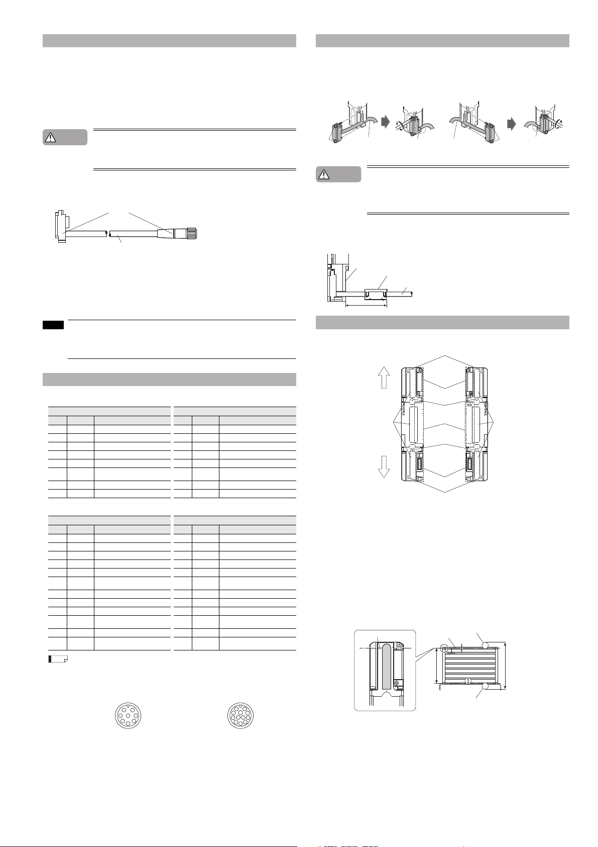
Dimensions and Specifications
If the length for a single SL-VHS unit is 710 mm or greater, use a compact E-to-E mounting bracket or
an E-to-E mounting bracket additionally as an intermediate support bracket. The following figures show
the example for the use of one compact E-to-E bracket or space-saving bracket.
φ5.8 Cable
9
6-M3 Depth4.5
C:
Protection
Model Beam a xes A: Length
SL-V08HS 8 150 140 185
SL-V12HS 12 230 220 265
SL-V16HS 16 310 300 345
SL-V20HS 20 390 380 425
SL-V24HS 24 470 460 505
SL-V28HS 28 550 540 585
SL-V32HS 32 630 620 665
SL-V36HS 36 710 700 745
SL-V40HS 40 790 780 825
SL-V44HS 44 870 860 905
SL-V48HS 48 950 940 985
SL-V52HS 52 1030 1020 1065
SL-V56HS 56 1110 1100 1145
SL-V60HS 60 1190 1180 1225
SL-V64HS 64 1270 1260 1305
SL-V72HS 72 1430 1420 1465
SL-V80HS 80 1590 1580 1625
SL-V88HS 88 1750 1740 1785
SL-V96HS 96 1910 1900 1945
SL-V104HS 104 2070 2060 2105
SL-V112HS 112 2230 2220 2265
SL-V120HS 120 2390 2380 2425
B: Detection
height
height
D: Beam axis
spacing
■ Parameter for IEC61508
T1 (Proof test interval)
PFHd (average frequency of a dangerous
failure per hour)
Hardware fault tolerance
Type of element
Failure response time
Safe state
*1 For PFHd of each SL-V, contact your nearest KEYENCE office.
*1
With no series connection: 8.2 x 10⁻⁹ or less
With series connection: 1.7 x 10
20 years
-8
1
Typ e B
Within a response time
OSSDs are in OFF-state
Units: mm
28.8
28
A
B
D
5
12
14 4.5
4.3
Units: mm
E F
20 5 22.5
or less
FE
C
7
SL-VHS-IM-E
Page 8

■ Response time (OSSD)
Reference
NOTE
Model
SL-V08HS 7 47
SL-V12HS 7.6 47.6
SL-V16HS 8.1 48.1
SL-V20HS 8.7 48.7
SL-V24HS 9.2 49.2
SL-V28HS 9.8 49.8
SL-V32HS 10.3 50.3
SL-V36HS 10.9 50.9
SL-V40HS 11.4 51.4
SL-V44HS 12 52
SL-V48HS 12.5 52.5
SL-V52HS 13.1 53.1
SL-V56HS 13.6 53.6
SL-V60HS 14.2 54.2
SL-V64HS 14.7 54.7
SL-V72HS 15.8 55.8
SL-V80HS 16.9 56.9
SL-V88HS 18 58
SL-V96HS 19.1 59.1
SL-V104HS 20.2 60.2
SL-V112HS 21.3 61.3
SL-V120HS 22.4 62.4
*1 If the interruption is present in the detection zone for less than 80 ms, the response time (OFF to ON) is to be 80 ms or
more to ensure that the OSSD keeps OFF state for more than 80 ms.
When connecting the SL-VHS units in series, the response time (ON to OFF) is the sum of the response
times of all the individual SL-VHS units.
When connecting the SL-V32HS (32 beam axes), SL-V24HS (24 beam axes), and SL-V12HS (12
beam axes) in series, the response time of each unit is 10.3 ms, 9.2 ms, and 7.6 ms respectively, and
the response time (ON to OFF) is 10.3 ms + 9.2 ms + 7.6 ms = 27.1 ms.
the response time (OFF to ON) is 27.1 ms + 40 ms = 67.1 ms.
Response time (OSSD)
ON to OFF OFF to ON
Units: ms
*1
1.6 m/s is the maximum speed of movement of the test piece to which the detection capability is maintained.
■ Current consumption
Model
SL-V08HS 56 70 52 65
SL-V12HS 63 72 58 66
SL-V16HS 69 74 64 67
SL-V20HS 75 75 70 68
SL-V24HS 81 77 76 69
SL-V28HS 87 79 81 69
SL-V32HS 93 80 86 70
SL-V36HS 98 82 91 71
SL-V40HS 103 84 96 72
SL-V44HS 108 85 100 73
SL-V48HS 113 87 104 74
SL-V52HS 117 88 109 74
SL-V56HS 122 90 112 75
SL-V60HS 126 91 116 76
SL-V64HS 130 93 120 77
SL-V72HS 137 96 126 78
SL-V80HS 144 98 132 80
SL-V88HS 149 101 136 81
SL-V96HS 154 104 140 83
SL-V104HS 159 107 143 84
SL-V112HS 162 109 146 86
SL-V120HS 165 112 147 87
When the center indicator is ON When the center indicator is OFF
Transmitter
Receiver
Tra n s m it t e r
Unit:mA
Receiver
Common specifications
Beam axis spacing/Lens diameter 20 mm/φ5 mm
Detection capability φ25 mm
Operating distance
Effective aperture angle
Light source Infrared LED (850 nm)
Operation form
Rating Power voltage 24 VDC +10 %, -20 % (Ripple P-P 10 % or less), Class 2
OSSD
Non safetyrelated output
Input
Protection circuit
Environmental
condition
Material
Approved
standards
*1 When the SL-VHS is used under ambient temperatures between 45 to 55 °C, the Maximum load current should not
exceed 300 mA.
*2 A pplies to situations when power is either off or disconnected.
*3 The wiring resistance between the OSSD output and the connected equipment (excluding the resistance of the cable)
must be 2.5 ohms or less to ensure operation. If the cable length is 15 m or more and the load’s current consumption is
200 mA or more, the wire resistance must be 1 ohm or less.
*4 When operating in ambient temperatures ranging from 45 to 55 °C, use incandescent lamps (24 VDC, 1 to 3 W) or LED
lamps (load current:10 to 100 mA).
*5 With IP-67conformity, the product is evaluated and proved by KEYENCE.
Model SL-VHS
0.1 m to 9.0 m (detection height of 1,260 mm or less)
0.1 m to 7.0 m (detection height of 1,400 mm or more)
Max. ±2.5 ° (When operati ng distance is 3 m (9.84 ft.) or more)
Turns on when no interruptions are present in t he detection zone
Output
Max. load current
Residual voltage (during ON ) Max. 2.5 V (with a cable l ength of 7 m (22.97 ft.))
OFF state voltage Max. 2.0 V (with a cable length of 7 m (22.97 ft.))
Leakage current
Max. capacitive load 1 µF (with a load resi stance of 100 Ω)
Load wiring resistance
AUX
Alert output
Clear/Blocked Output
State information output 1, 2
Muting lamp output
EDM input Short-circuit current 10 mA
Wait i nput
Reset input
Muting input 1, 2
Override input
Enclosure protection
Overvoltage Category II
Operating ambient temperature -10 to +55 °C (No freezing )
Storage ambient temperature -25 to +60 °C (No freezing )
Operating relative humidity 15 % to 85 %RH (No condensation)
Storage relative humidit y 15 % to 95 %RH
Surrounding light
Vibration
Shock
Main unit case Aluminum
Upper case/Lower case Zinc die-cast
Front cover Polycarbonate, SUS304
EMC
Safety
EMS IEC61496-1, EN61496-1, UL61496-1
EMI EN55011 ClassA , FCC Part15B ClassA, ICES-003 Class A
2 outputs each for PNP and NPN.
Can be changed by using the connector cable
Output with automatic PNP/NPN switching function, 50 mA
Incandescent lamp (24 VDC, 1 to 7 W) or LED lamp
(load current :10 to 300 mA)
Short-circuit current 2.5 mA
Reverse current protection, short-circuit protection for each
output, surge protection for each output
Incandescent lamp: 5,000 lx or less. Sunlight: 20,000 lx or less
10 to 55 Hz, 0.7 mm compound am plitude,
20 sweeps each in X, Y, and Z directions
100 m/s
in X, Y, Z directions 1,000 times each axis
IEC61496-1, EN61496-1, UL61496-1 (Type 4 ESPE)
IEC61496-2, UL61496-2, EN61496-2 (Type 4 AOPD)
IEC61508, EN61508 (SIL3), IEC62061, EN62061 (SIL3)
EN ISO13849-1:2008 (Category 4, PL e)
*1
500 mA
*2
Max. 100 µA
*3
Max. 2.5 Ω
max.
*4
can be connected
*5
IP65, IP67
2
(Approx. 10 G) 16 ms pulse,
UL508, UL1998
SL-VHS-IM-E
8
Page 9

Checklist
Start
Stop
You are fully responsible for performing the risk assessment on your machine application, taking into
account performing maintenance and inspections, which are critical factor for appropriate risk
assessment. In addition, it is a responsibility for the responsible personnel to train the machine operators regarding inspection and maintenance of the machine and the SL-VHS.
■ Inspection before operation (Initial inspection)
When the installation of the SL-VHS is completed, the responsible personnel must verify the operation of
the SL-VHS in accordance with the checklist shown below. Note that the following inspection items
comprise only a bare minimum inspection. KEYENCE Corporation strongly recommends including the
necessary checking items into this checklist based on the judgment of the responsible personnel since
additional criteria may be necessary depending on both the machine to which the SL-VHS is installed
and the laws, rules, regulations and standards in the country or region in which the SL-VHS is used/
installed.
(1) Pre-check for installation condition
❑
The machine on which the SL-VHS is installed can be caused to stop running by the OFF-state of OSSD.
❑ The SL-VHS is installed so that the machine operator cannot go into or approach the hazardous
zone or hazard without passing through the detection zone.
❑ The device to activate the override is installed so that it cannot be operated if there are any per-
sonnel within the hazardous zone.
❑
The SL-VHS has been installed at a distance greater than or equal to the minimum safety distance
required .
❑ If there are glossy surfaces nearby, move them so that they are beyond the minimum installation
distance.
❑ The SL-VHS is installed at a location free from light interference, for example fluorescent lamps.
❑ The transmitters and receivers are paired correctly.
❑ The beam axis spacing (detection capability) is the same between the transmitter and the
receiver when installing the SL-VHS.
❑
The muting devices fulfill the conditions specified in this instruction manual and the requirements of the laws,
rules, regulations and standards in the country or region in which the SL-VHS and those devices are used.
❑ The devices used to activate the override fulfill the conditions specified in this manual and
requirements of the laws, rules, regulations and standards in the country or region in which the
SL-VHS and those devices are used.
❑ Risk assessment was performed on your own responsibility based on your machine application,
and then the installation of SL-V was also based on its result.
(2) Pre-check for wiring
❑ The SL-VHS power supply is 24 VDC, fulfill the conditions for the power supply as specified in this
instruction manual.
❑ The transmitter and receiver cables are installed correctly.
❑
The two of OSSD outputs provided in the SL-VHS are both used as a safety-related machine control system.
❑ The polarity is not reversed with the connection to the power supply.
❑ In case of using PNP output type cable, the OSSD is not short-circuited to +24 V, and the load is
between the OSSD and 0 V.
❑ In case of using NPN output type cable, the OSSD is not short-circuited to 0 V, and the load is
between the OSSD and +24 V.
❑ When two or more SL-VHS are connected in series, they are connected using the dedicated
series connection cable, which is not cut or extended.
❑ Alert output, AUX output, Clear/Blocked Output, and state information output are not used as
safety output for safety systems.
❑ The cable sheaths are not damaged. The protection against the disconnection or short-circuit of
cable, which might be caused by crushing or being caught in a machine, is taken into account.
❑
If two or more sets of the SL-VHS units are used in the vicinity of each other, the protection measures
against light interference is done through a series connection method or light interference prevention
method.
❑ All of NON-SAFETY-RELATED functions described in this instruction manual are not a part of /
whole of safety-related machine control system.
(3) Pre-check test while the machine is stopped.
You should do the following pre-check test with the test piece in order to make sure the operation of
the SL-VHS while the machine is stopped.
❑
The OSSD indicator on the SL-VHS lights in red and the OSSD turns OFF while the test piece is
present in the detection zone. The following figure shows the movement procedure of the test piece.
■ Inspection prior to daily operation (Daily inspection)
You should check the SL-VHS operation and the machine operation according to the following checklist prior to daily operation.
Note that the following inspection items comprise only a bare minimum inspection. KEYENCE Corporation strongly recommends including the necessary checking items into this checklist based on the
judgment of the responsible personnel since additional criteria may be necessary depending on both
the machine to which the SL-VHS is installed and the laws, rules, regulations and standards in the
country or region in which the SL-VHS is used/installed.
Also, the responsible personnel has a responsibility to instruct the machine operators about the
inspection and maintenance of the machine and the SL-VHS.
The result of this inspection must be kept on record along with the machine log.
(1) Pre-check for installation condition
❑ The SL-VHS is installed so that the machine operator cannot go into or approach the hazardous
zone or hazard without passing through the detection zone.
❑
The SL-VHS has been installed at a distance greater than or equal to the minimum safety distance
required.
❑ The SL-VHS is installed at a location free from light interference, for example fluorescent lamps.
❑ The cable sheaths are not damaged. The protection against the disconnection or short-circuit of
cable, which might be caused by crushing or being caught in a machine, is taken into account.
Additionally, you should perform the following inspections as described in "Inspection before
operation".
(3) Pre-check test while the machine is stopped
(4) Pre-check test while the machine is operating
❑ There is no change of installation that would influence the result of your original risk assessment.
■ Regular (periodical) inspection
The responsible personnel must perform a regular inspection at least once every six months.
Note that the following inspection items comprise only a bare minimum inspection. KEYENCE Corporation strongly recommends including the necessary checking items into this checklist based on the
judgment of the responsible personnel since additional criteria may be necessary depending on both
the machine to which the SL-VHS is installed and the laws, rules, regulations and standards in the
country or region in which the SL-VHS is used/installed.
The result of this inspection must be kept on record along with the machine log.
(1) Additional inspection items
❑ The actual distance between the hazardous zone or hazards and the SL-VHS still keeps greater
than the calculated safety distance.
❑ The stop time of the machine connected to the SL-VHS has not increased.
❑ There are no loose screws in the mounting bracket.
❑ The unit connection cable or the series connection cable is fastened tightly to the SL-VHS with no
loose screws.
❑ The OSSD is connected correctly to the machine.
❑ There is no damage to the SL-VHS that may influence IP65 structure.
❑ The surface of the SL-VHS is not polluted or damaged.
❑ Beam axes must be aligned. If it is out of alignment, adjust the beam axes to be aligned.
❑ There is no change of installation that would influence the result of your original risk assessment.
❑
The OSSD indicator and all bar LEDS light in green if no test piece is present in the detection zone.
❑
When the EDM function is applied, the SL-VHS goes to a lockout condition and the OSSD indicator on
the SL-VHS lights in red if the EDM input opens while the test piece is present in the detection zone.
(4) Pre-check test while the machine is operating.
The purpose of this pre-check test is to make sure that the machine (hazards) stops its operation.
This test must be done after you completely make sure that there is nobody in the hazardous zone.
❑ The machine stops if the test piece is present in the detection zone. It is recommended to try
three locations of test piece: near the transmitter, near the receiver, and in the central area of the
detection zone.
❑ The machine (hazard) still stops its operation as long as the test piece is present in the specified
detection zone. This test should be done for the whole detection zone.
❑ The machine (hazard) stops its operation when the power for the SL-VHS is disconnected.
❑ Minimum safety distance is ensured, which has been calculated according to the laws, regula-
tions, and standards of the country and region in which the SL-VHS is installed.
9
SL-VHS-IM-E
Page 10

WARRANTIES AND DISCLAIMERS
Copyright (c) 2013 KEYENCE CORPORATION. All rights reserved.
12525E 1073-2 96M12525 Printed in Japan
(1) KEYENCE warrants the Products to be free of defects in materials and
workmanship for a period of one (1) year from the date of shipment. If any
models or samples were shown to Buyer, such models or samples were used
merely to illustrate the general type and quality of the Products and not to
represent that the Products would necessarily conform to said models or
samples. Any Products found to be defective must be shipped to KEYENCE
with all shipping costs paid by Buyer or offered to KEYENCE for inspection
and examination. Upon examination by KEYENCE, KEYENCE, at its sole
option, will refund the purchase price of, or repair or replace at no charge any
Products found to be defective. This warranty does not apply to any defects
resulting from any action of Buyer, including but not limited to improper
installation, improper interfacing, improper repair, unauthorized modification,
misapplication and mishandling, such as exposure to excessive current, heat,
coldness, moisture, vibration or outdoors air. Components which wear are not
warranted.
(2) KEYENCE is pleased to offer suggestions on the use of its various Products.
They are only suggestions, and it is Buyer's responsibility to ascertain the
fitness of the Products for Buyer’s intended use. KEYENCE will not be
responsible for any damages that may result from the use of the Products.
(3) The Products and any samples ("Products/Samples") supplied to Buyer are
not to be used internally in humans, for human transportation, as safety
devices or fail-safe systems, unless their written specifications state otherwise.
Should any Products/Samples be used in such a manner or misused in any
way, KEYENCE assumes no responsibility, and additionally Buyer will
indemnify KEYENCE and hold KEYENCE harmless from any liability or
damage whatsoever arising out of any misuse of the Products/Samples.
(4) OTHER THAN AS STATED HEREIN, THE PRODUCTS/SAMPLES ARE
PROVIDED WITH NO OTHER WARRANTIES WHATSOEVER. ALL
EXPRESS, IMPLIED, AND STATUTORY WARRANTIES, INCLUDING,
WITHOUT LIMITATION, THE WARRANTIES OF MERCHANTABILITY,
FITNESS FOR A PARTICULAR PURPOSE, AND NON-INFRINGEMENT OF
PROPRIETARY RIGHTS, ARE EXPRESSLY DISCLAIMED.
IN NO EVENT SHALL KEYENCE AND ITS AFFILIATED ENTITIES BE
LIABLE TO ANY PERSON OR ENTITY FOR ANY DIRECT, INDIRECT,
INCIDENTAL, PUNITIVE, SPECIAL OR CONSEQUENTIAL DAMAGES
(INCLUDING, WITHOUT LIMITATION, ANY DAMAGES RESULTING FROM
LOSS OF USE, BUSINESS INTERRUPTION, LOSS OF INFORMATION,
LOSS OR INACCURACY OF DATA, LOSS OF PROFITS, LOSS OF
SAVINGS, THE COST OF PROCUREMENT OF SUBSTITUTED GOODS,
SERVICES OR TECHNOLOGIES, OR FOR ANY MATTER ARISING OUT
OF OR IN CONNECTION WITH THE USE OR INABILITY TO USE THE
PRODUCTS, EVEN IF KEYENCE OR ONE OF ITS AFFILIATED ENTITIES
WAS ADVISED OF A POSSIBLE THIRD PARTY’S CLAIM FOR DAMAGES
OR ANY OTHER CLAIM AGAINST BUYER. In some jurisdictions, some of
the foregoing warranty disclaimers or damage limitations may not apply.
BUYER'S TRANSFER OBLIGATIONS:
If the Products/Samples purchased by Buyer are to be resold or delivered to a
third party, Buyer must provide such third party with a copy of this document,
all specifications, manuals, catalogs, leaflets and written information provided
to Buyer pertaining to the Products/Samples.
E 1101-3
Document Control No. 825BE028-09
SL-VHS-IM-E
10
 Loading...