

Page 1
96008E
Safety Light Curtain
SL-V Ver.3 Configuration Software (SL-VH1S)
SL-V Configurator
User's Manual
Read this manual and the SL-V user's manual before using the product in order to
understand the features.
Always keep this manual in a safe place for future reference.
Page 2
Introduction
Important
Note
This user's manual describes functions and handling of the SL-VH1S <SL-V Configurator>, the dedi-
cated software for the SL-V Ver.3. Read this user's manual thoroughly before operating <SL-V Configura-
tor> in order to understand the software features, and keep this user's manual readily available for
reference. Ensure that the end user of this product receives this manual.
Before using <SL-V Configurator>, make sure to read the "Safety Light Curtain SL-V Series Ver.3 Instruc-
tion Manual" and "Safety Light Curtain SL-V Series Ver.3 User's Manual" for correct use. Failure to follow
the instruction in this manual, "Safety Light Curtain SL-V Series Ver.3 Instruction Manual", and "Safety
Light Curtain SL-V Series Ver.3 User's Manual" results in significant harm to the machine operators
including serious injury or death.
■
Safety headings
This user's manual uses the following headings to display important safety information. Strict adherence
to the instructions next to these heading is required at all times.
Provides cautions and restrictions that must be followed in operations.
Provides additional information for proper operation.
Reference
Provides advanced and useful information for operation.
Indicates reference pages in this or another manual.
Page 3

Terms of License Agreement on Use of the Software
Software License Agreement
The use of [SL-VH1S <SL-V Configurator>] (hereinafter referred to as [this software]) is subject to the
terms outlined in this software license agreement (hereinafter referred to as [this agreement]) and to the
customers consent to this agreement. The customer's use or duplication of this software, in whole or in
part, constitutes the customer's consent to enter into this agreement.
Article 1 (Usage Rights)
1 Contingent of the customer's compliance with the terms of this agreement, KEYENCE Corporation
(hereinafter referred to as KEYENCE) extends to the customer non-exclusive usage rights.
2 The customer may install this software without the limit of the number of the licenses, provided that
this software is used only in the same corporation in order to use our product you have purchased.
Article 2 (Limitations on Duplication)
The customer may make no more than 1 copy of this software for backup purposes only.
Article 3 (Prohibitions)
The customer is prohibited from doing the following with this software.
a. Additions or changes to any or all of the functions of this software.
However, installation of updates or new features provided by KEYENCE is expressly allowed.
b. Reverse compiling or reverse assembling of this software for the purposes of reverse engineering.
c. Sale, transfer, redistribution, license, rental or lease to the third party.
This does not include instances where permission has been obtained from KEYENCE in advance.
Article 4 (Copyright)
The copyrights of this software and all associated documentation are the property of KEYENCE.
Article 5 (Exemption of Liability)
KEYENCE shall not be held liable by the user or third party for any damages arising from the use of
the software.
Article 6 (Support)
Based on this agreement, KEYENCE agrees to provide the customer with technical support in
response to customer questions regarding this software. However, KEYENCE makes no guarantee
that the technical support offered will meet the customer's needs.
Article 7 (Termination of Agreement)
1 Should the customer destroy this software and any backup copies, this agreement will
automatically expire with the customer's cessation of use of this software.
2 KEYENCE reserves the right to unilaterally terminate this agreement should the customer violate
any of the terms of this agreement. In this instance, this software and all copies should be
immediately returned to KEYENCE for destruction.
3 Should KEYENCE be caused damages by the customer's violation of this agreement, the
customer will compensate KEYENCE for those damages.
Article 8 (Basis in Law)
This agreement is to be adjudicated according to Japanese law.
Trademarks
• Windows XP/Vista/7 are the registered trademarks of Microsoft Corporation, U.S.A.
• Adobe, the Adobe logo, and Reader are the trademarks or registered trademarks of Adobe System
Incorporated in the United States and other countries.
• Other company or product names mentioned in this manual are trademarks or registered trademarks
of their respective companies. The following marks are not used in this manual: TM, ®.
SL-VH1S-NO0-E
96008E
1
Page 4

Table of Contents
Introduction
Terms of License Agreement on Use of the Software ............................................................. 1
Table of Contents .................................................................................................................... 2
Chapter 1 Before Use
1-1 Checking Package Contents ...................................................................................... 1-2
1-2 Using the Configurator ............................................................................................... 1-3
1-3 System Requirements ................................................................................................ 1-4
1-4 Installing the <SL-V Configurator> ............................................................................. 1-5
Preparation ................................................................................................................................... 1-5
Notes for Windows XP.................................................................................................................. 1-5
Notes for Windows Vista/7 ........................................................................................................... 1-5
Installation .................................................................................................................................... 1-6
Uninstalling the <SL-V Configurator> ........................................................................................... 1-6
1-5 Connecting the SL-V and the Computer .................................................................... 1-7
Names and Functions of SL-V1UB Interface Unit Parts............................................................... 1-7
Connecting ................................................................................................................................... 1-8
Chapter 2 Basic Operation
2-1 Names of Parts in Main Window ................................................................................ 2-2
Menu Bar ...................................................................................................................................... 2-2
Toolbar ......................................................................................................................................... 2-2
Configuration Tab ......................................................................................................................... 2-3
Function Configuration Area......................................................................................................... 2-3
Status Bar..................................................................................................................................... 2-3
2-2 Flow of Basic Operation ............................................................................................. 2-4
Creating the Configuration on the PC........................................................................................... 2-4
Uploading the Configuration to the SL-V ...................................................................................... 2-4
2-3 Startup and Exiting the <SL-V Configurator> ............................................................. 2-5
Startup of the <SL-V Configurator> ..............................................................................................2-5
Exiting the <SL-V Configurator>................................................................................................... 2-7
2-4 Configuring the Functions .......................................................................................... 2-8
2-5 Setup of the Password ............................................................................................... 2-9
2-6 Login/Logout............................................................................................................. 2-10
Logging In................................................................................................................................... 2-10
Logging Out................................................................................................................................ 2-10
2-7 Uploading the Configuration to the SL-V.................................................................. 2-11
2-8 Saving and Using the Configuration on the PC........................................................ 2-13
Saving the Configuration ............................................................................................................ 2-13
Opening an Existing Configuration ............................................................................................. 2-13
2
SL-VH1S-NO0-E
Page 5

Chapter 3 Configuration of Each Function
3-1 Safety Related Configuration ..................................................................................... 3-2
Muting Configuration .................................................................................................................... 3-2
Override Function ......................................................................................................................... 3-2
Interlock Configuration.................................................................................................................. 3-3
EDM Function / Adjustment.......................................................................................................... 3-3
3-2 Non Safety Related Configuration.............................................................................. 3-4
Emitting Frequency....................................................................................................................... 3-4
Alert Output .................................................................................................................................. 3-4
State Information Output .............................................................................................................. 3-4
Center Indicator ............................................................................................................................ 3-5
3-3 Blanking Area ............................................................................................................. 3-6
3-4 Muting Area ................................................................................................................ 3-7
Chapter 4 Other Functions
Table of Contents
4-1 Creating New Settings................................................................................................ 4-2
4-2 Changing the Type Configuration............................................................................... 4-3
4-3 Loading Configurations from the SL-V ....................................................................... 4-5
4-4 Verifying the Configuration between PC and SL-V .................................................... 4-6
4-5 Monitoring the Received Light Intensity on the SL-V ................................................. 4-7
4-6 Changing the Password ............................................................................................. 4-8
4-7 Initializing the SL-V..................................................................................................... 4-9
4-8 Outputting the Settings ............................................................................................. 4-11
Printing ....................................................................................................................................... 4-11
Outputting in the CSV format...................................................................................................... 4-12
Appendix
A-1 Error Messages ..........................................................................................................A-2
A-2 Operation Menu List ...................................................................................................A-3
A-3 Index........................................................................................................................... A-4
SL-VH1S-NO0-E
3
Page 6

Table of Contents
MEMO
4
SL-VH1S-NO0-E
Page 7

1
Before Use
1-1 Checking Package Contents . . . . . . . . . . . . . . . . . . . . . . . . . . 1-2
1-2 Using the Configurator. . . . . . . . . . . . . . . . . . . . . . . . . . . . . . . 1-3
1-3 System Requirements . . . . . . . . . . . . . . . . . . . . . . . . . . . . . . . 1-4
1-4 Installing the <SL-V Configurator> . . . . . . . . . . . . . . . . . . . . . 1-5
1-5 Connecting the SL-V and the Computer . . . . . . . . . . . . . . . . . 1-7
SL-VH1S-NO1-E
1-1
Page 8

Before Use
1
Note
1-1 Checking Package Contents
The following items should be found in the package. Make sure that each of these items is present.
Installation CD-ROM x1
This disc contains the <SL-V Configurator> installer.
Keep this disk in a safe place after installation.
It is recommended that the CD-ROM be backed up in case of damage to or loss of the disk.
1-2
SL-VH1S-NO1-E
Page 9
1
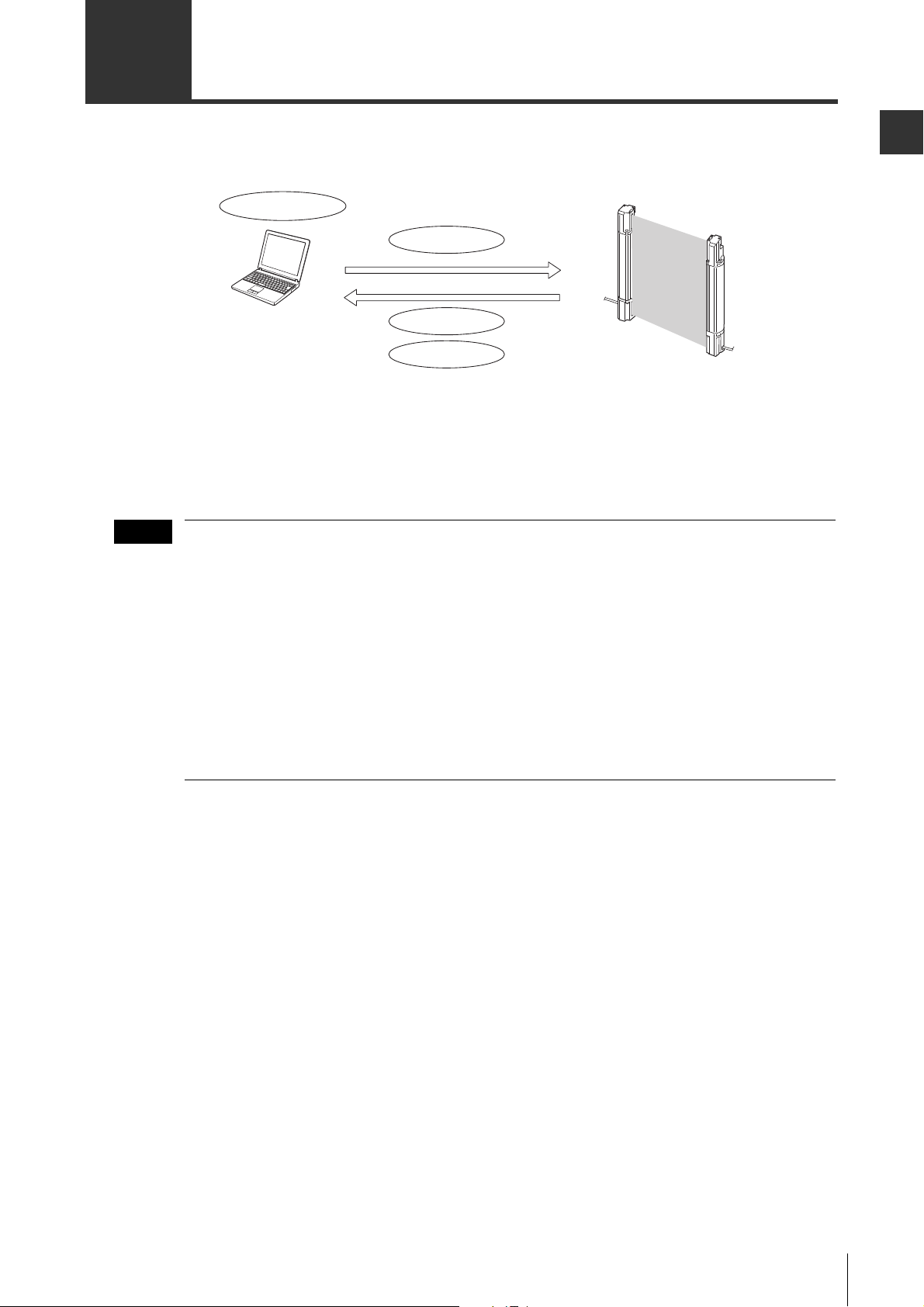
1-2 Using the Configurator
Upload configurations
Read configurations
Create/Save configurations
Monitor light intensity
Computer
SL-V Series Ver.3
Note
The <SL-V Configurator> allows various configurations on the SL-V Series version 3 to be configured
from the PC.
• Settings can be configured even when the computer is not connected to the SL-V.
• The receiver on the main unit is needed to configure and upload configuration. (If the SL-V is under the
serial connection, only the main unit is required when the configuration is uploaded.)
Before Use
• A separate interface unit such as the SL-V1UB and USB 1.1-compatible USB cable (included
with the SL-V1UB) or the SL-V connection cable are required to connect the SL-V to a computer.
• Only one interface unit can be connected to each computer. 1-to-many or many-to-1 connection
are not possible.
• All settings can be configured with SL-V Ver. 2/Ver.1 in a serial connection as subunits.
However, the main unit must be Ver. 3.
• The SL-VHS cannot be used as a main unit.
• When settings are being configured with <SL-V Configurator> (with the SL-V1UB connected to
the SL-V), the control output (OSSD) of the SL-V turns OFF. Also, when the safety control unit
SL-T11R is connected, the indicator of SL-T11R lights up differently (arbitrary lightup) from
when in normal use. After settings are configured with <SL-V Configurator>, disconnect the SLV1UB from the SL-V before use.
SL-VH1S-NO1-E
1-3
Page 10
Before Use
1
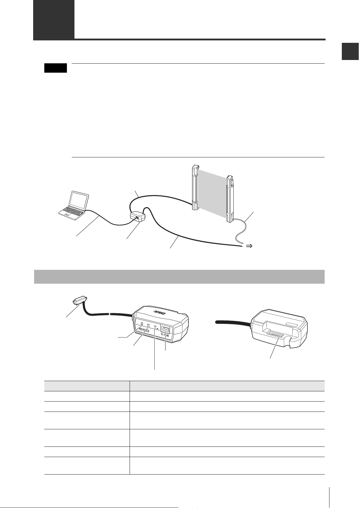
Computer
Interface unit
SL-V1UB cable
SL-V connection cable
(Receiver side)
SL-V connection cable
(Transmitter side)
SL-V Ver. 3
Receiver
Transmitter
Power supply
Interface unit
SL-V1UB
USB cable OP-51580
supplied with the SL-V1UB
Note
1-3 System Requirements
The system requirements for the <SL-V Configurator> are as follows.
CPU Pentium III 1.2 GHz or greater
Compatible OS
Memory capacity 512 MB or greater
Hard disk space 30 MB or greater
CD-ROM drive Required
Communication interface USB 1.1/2.0
Display XGA (1024 x 768) or greater, 256 colors or greater (High Color or greater
Operating environment .NET Framework 2.0 installed
* Confirm system requirements of each OS separately.
*1 Only Windows 7 supports 64-bit platform.
The operating system is compatible with Japanese, English, German, Italian, French and Chinese languages.
*2 If ".NET Framework 2.0" is not installed on the computer that <SL-V Configurator> will be installed on, ".NET
Framework" will be installed automatically when <SL-V Configurator> is installed.
To install ".NET Framework 2.0", the following conditions must be met.
• Hard disk free space: 300 MB or greater
• Windows Installer 3.0 or later is installed
• Internet Explorer 6 or later is installed
*1
Windows XP (SP3 and later versions)
Windows Vista (SP1 and later versions)
Windows 7
recommended)
*2
1-4
When the SL-V is positively grounded using the SL-V connection cable for the NPN output type,
do not ground on the computer side. (Communication cannot be established if grounded.)
SL-VH1S-NO1-E
Page 11

1
1-4 Installing the <SL-V Configurator>
Note
This section explains how to install the <SL-V Configurator> on your computer.
Preparation
Confirm the following before installing the software.
It is recommended that the CD-ROM be backed up in case of damage to or loss of the disk.
Hard disk space
The <SL-V Configurator> must be installed to a hard disk. The hard drive for installation must have at
least 30 MB (330 MB if .NET Framework2.0 is not installed) of free space. If there is not enough free
space on the drive, you must clear some space.
Installing to a Windows machine
The <SL-V Configurator> runs under a Windows operating system. It must also be installed on a
Windows operating system. Make sure that Windows XP/Vista/7 is installed and operating properly on
the target PC.
Before Use
USB port
The USB port on the computer must be usable to upload configuration or monitor the SL-V series. Refer
to the user’s manual for your computer for more information.
Help files
The help file for the <SL-V Configurator> is a PDF file. Adobe Systems Adobe Reader must be installed
on your computer to use the help file.
Adobe Reader can be downloaded from the Adobe Systems website (http://www.adobe.com/).
Notes for Windows XP
User privileges
Set the following access rights if the <SL-V Configurator> is installed in the default folder (C:/Program
files/Keyence/SL-V Configurator/).
• Grant Administrator privileges to users who will be using the <SL-V Configurator>.
Notes for Windows Vista/7
User privileges
Set the following access rights if the <SL-V Configurator> is installed in the default folder (C:/Program
files/Keyence/SL-V Configurator/).
• Grant Administrator privileges to users who will be using the <SL-V Configurator>.
If the "User account control" screen appears during installation, click "Continue"
SL-VH1S-NO1-E
1-5
Page 12
1-4 Installing the <SL-V Configurator>
1
Note
Note
Before Use
Installation
This section explains how to install the software, using the following drive setup.
C drive: Hard disk drive
E drive: CD-ROM drive
Start Windows and insert the "SL-V Configurator Installer CD-ROM" into the CD-ROM drive.
• The install program will be started by the computer’s auto run function. If the install program does not
start, select "Run..." from the Start menu and enter "e:/set up" in the "Run" dialog box, then press the
[OK] button.
• Install the software as specified by the installer.
Log in as a user with Administrator privileges when installing.
<SL-V Configurator> Installation folder
If the <SL-V Configurator> is installed under the default settings, the software will be installed in the
folder listed below.
C:/Program files/Keyence/SL-V Configurator/
Uninstalling the <SL-V Configurator>
Use "Add or Remove Programs" from the Windows control panel to uninstall the <SL-V Configurator>.
Log in as a user with Administrator privileges when uninstalling.
1-6
SL-VH1S-NO1-E
Page 13
1
1-5
Note
Computer
Interface unit
SL-V1UB cable
SL-V connection cable
(Receiver side)
SL-V connection cable
(Transmitter side)
SL-V Ver. 3
Receiver
Transmitter
Power supply
Interface unit
SL-V1UB
USB cable OP-51580
supplied with the SL-V1UB
SL-V connector
Power indicator
SL-V communication indicator
PC communication indicator
USB port
(mini B)
SL-V connection cable (receiver)
connector
<Front side> <Rear side>
Connecting the SL-V and the Computer
This section explains how to connect the SL-V Configurator and the computer.
• The interface unit SL-V1UB and USB 1.1-compatible USB cable (Supplied with the SL-V1UB) and
the SL-V connection cable are required to connect the SL-V to a computer.
• Only one interface unit can be connected to each computer. 1-to-many and many-to-1
connections are not possible.
• All settings can be configured with SL-V Ver.2/Ver.1 in a serial connection as subunits.
However, the main unit must be Ver.3.
• The SL-VHS cannot be used as a main unit.
• When settings are being configured with <SL-V Configurator> (with the SL-V1UB connected to
the SL-V), the control output (OSSD) of the SL-V turns OFF. Also, when the safety control unit
SL-T11R is connected, the indicator of SL-T11R lights up differently (arbitrary lightup) from
when in normal use. After settings are configured with <SL-V Configurator>, disconnect the SLV1UB from the SL-V before use.
Before Use
Names and Functions of SL-V1UB Interface Unit Parts
Name Explanation
SL-V connector Connect to the SL-V receiver
Power indicator Illuminates green when the power to the SL-V1UB is supplied.
•
SL-V communication lamp
PC communication indicator
USB port (mini B) Connects to the computer.
SL-V connection cable (receiver
side) connector
Illuminates orange when communication with the SL-V device is possible.
•
Blinks orange during communicating with the SL-V device.
•
Illuminates orange when communication with the computer is possible.
•
Blinks orange during communicating with the computer.
Connects to the SL-V connection cable (receiver side).
SL-V1UB
KEYENCE CORPORA
http://www
.keyenec. com/
MEDE IN JAP
TION
AN
SL-VH1S-NO1-E
1-7
Page 14
1-5 Connecting the SL-V and the Computer
1
Note
SL-V connection cable
(Black coating)
USB cable included with the SL-V1UB
Connect to the USB port on the computer
Before Use
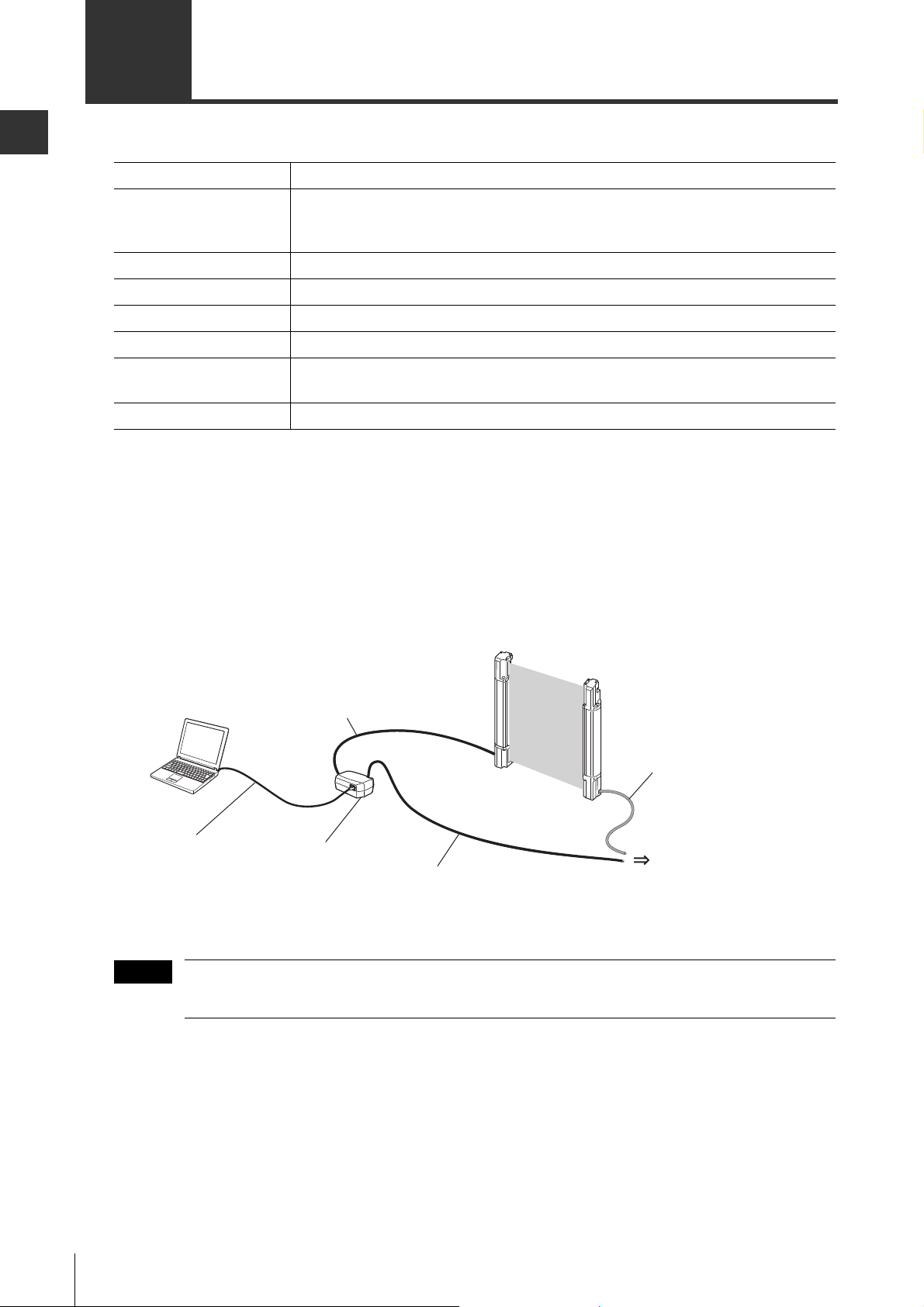
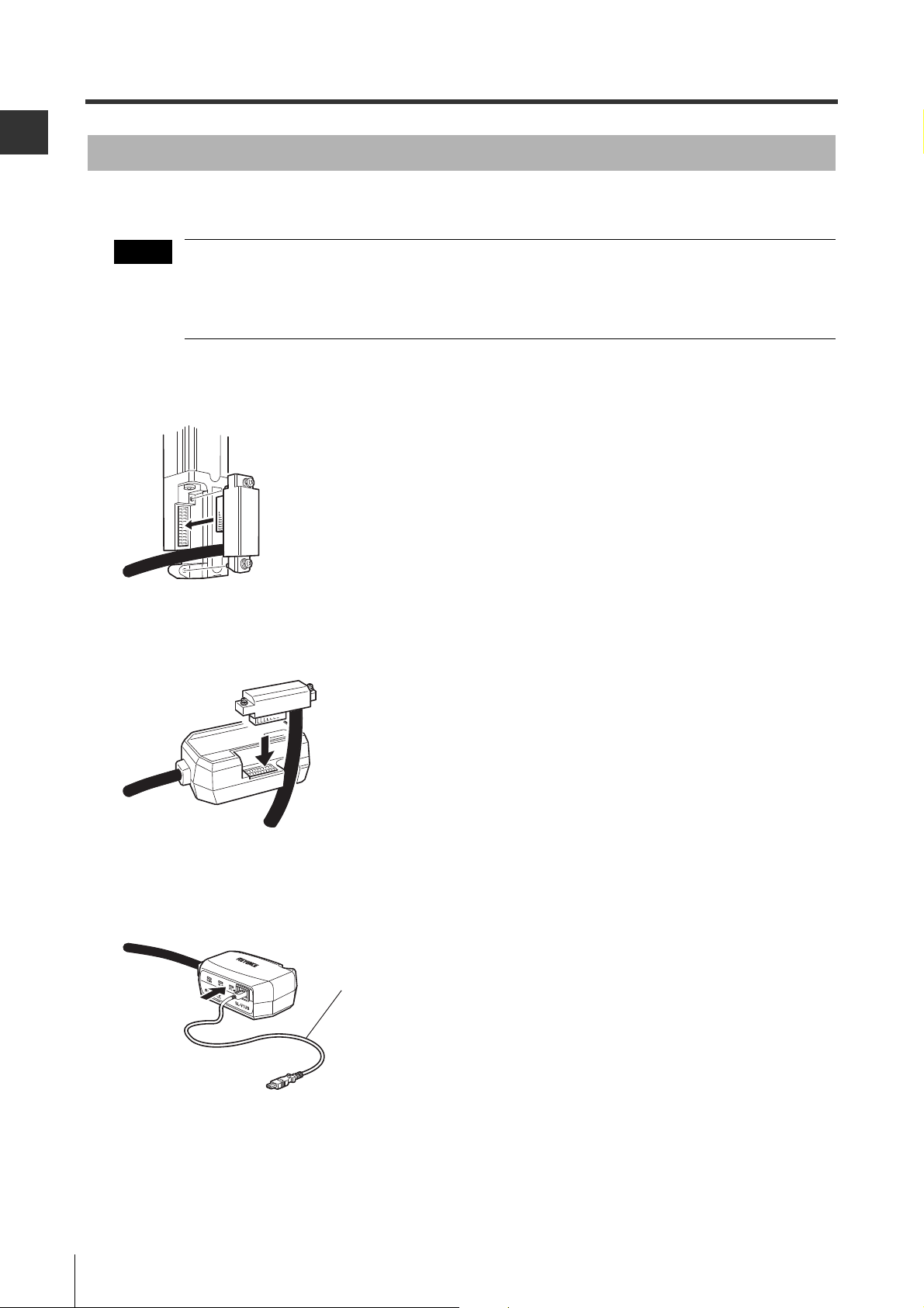
Connecting
This section explains how to connect the SL-V and the computer.
• Turn on the power after all of the connections are completed.
• Turn off the power before removing any of the connectors.
• When the SL-V is positively grounded using the SL-V connection cable for the NPN output type,
do not ground on the computer side. (Communication cannot be established if grounded.)
1 Connect the SL-V1UB interface unit cable to the SL-V receiver.
2 Connect SL-V device cable (receiver) to the SL-V1UB interface unit.
TION
KEYENCE CORPORA
MEDE IN JAP
http://www.keyenec. com
/
AN
SL-V1UB
3 Connect the SL-V1UB to the computer with the USB cable connected to the SL-V1UB device.
1-8
SL-VH1S-NO1-E
Page 15
1
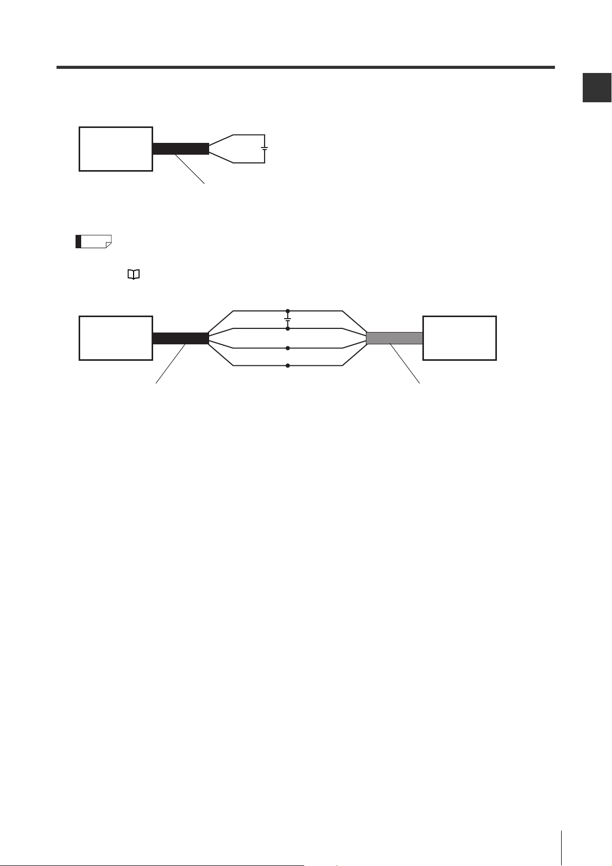
4 Turn on power.
Refer to the "SL-V Series Ver. 3 Safety
Light Curtain Instruction Manual" or the
"SL-V Series Ver. 3 Safety Light Curtain
User’s Manual" for more information on
wiring.
SL-V connection cable (receiver)
24V
Brown
Blue
SL-V1UB
SL-V connection cable (receiver) SL-V connection cable (transmitter)
24V
Brown
Blue
Orange
Orange/Black
Brown
Blue
Orange
Orange/Black
SL-V1UB SL-V
(Transmitter)
1-5 Connecting the SL-V and the Computer
Before Use
Reference
To monitor light intensity, connect SL-V connection cable (transmitter) to the SL-V device transmitter.
Turn on the power and connect the communication line to the transmitter.
"4-5 Monitoring the Received Light Intensity on the SL-V" (Page4-7)
SL-VH1S-NO1-E
1-9
Page 16

Before Use
1
1-5 Connecting the SL-V and the Computer
MEMO
1-10
SL-VH1S-NO1-E
Page 17

2
Basic Operation
2-1 Names of Parts in Main Window . . . . . . . . . . . . . . . . . . . . . . . 2-2
2-2 Flow of Basic Operation . . . . . . . . . . . . . . . . . . . . . . . . . . . . . 2-4
2-3 Startup and Exiting the <SL-V Configurator> . . . . . . . . . . . . . 2-5
2-4 Configuring the Functions . . . . . . . . . . . . . . . . . . . . . . . . . . . . 2-8
2-5 Setup of the Password . . . . . . . . . . . . . . . . . . . . . . . . . . . . . . 2-9
2-6 Login/Logout . . . . . . . . . . . . . . . . . . . . . . . . . . . . . . . . . . . . . 2-10
2-7 Uploading the Configuration to the SL-V . . . . . . . . . . . . . . . . 2-11
2-8 Saving and Using the Configuration on the PC . . . . . . . . . . . 2-13
SL-VH1S-NO2-E
2-1
Page 18
Basic Operation
2
Menu Bar
Toolbar
Configuration Tab
Function
Configuration
Area
Status Bar
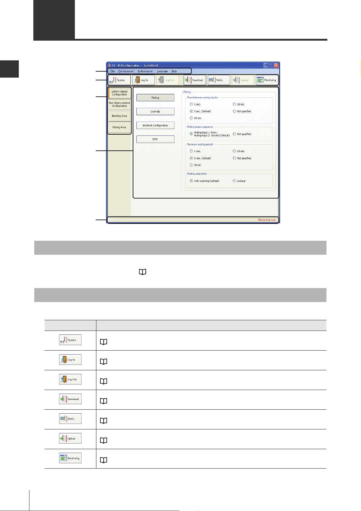
2-1 Names of Parts in Main Window
This section describes the names of parts in <SL-V Configurator> main window and outline of its functions.
Menu Bar
This displays the menu to execute each function.
For list of operation menu, refer to "A-2 Operation Menu List" (Page A-3).
Toolbar
Buttons for frequently used function is here.
Icon Description
This will configure the model configuration.
"4-2 Changing the Type Configuration" (Page 4-3)
This will login to SL-V.
"2-6 Login/Logout" (Page 2-10)
This will logout from SL-V.
"2-6 Login/Logout" (Page 2-10)
This will read out the configuration from the SL-V.
"4-3 Loading Configurations from the SL-V" (Page 4-5)
This will verify the configuration with the SL-V.
"4-4 Verifying the Configuration between PC and SL-V" (Page 4-6)
This will upload the configuration to the SL-V.
"2-7 Uploading the Configuration to the SL-V" (Page 2-11)
This will monitor the amount of receiving light at the SL-V.
"4-5 Monitoring the Received Light Intensity on the SL-V" (Page 4-7)
2-2
SL-VH1S-NO2-E
Page 19

2
Configuration Tab
2-1 Names of Parts in Main Window
Item that can be configured in the function configuration area is switched by clicking on the
Configuration tab.
Item Description
Safety Related
Configuration
Non Safety Related
Configuration
Blanking Area Beam axis where the blanking is enabled can be configured.
Muting Area Beam axis where the muting is enabled can be configured.
This will configure the safety related configurations, such as muting or interlock.
"3-1 Safety Related Configuration" (Page 3-2)
This will configure the functions useful to control, such as state information output or how
the indicator is turned on.
"3-2 Non Safety Related Configuration" (Page 3-4)
"3-3 Blanking Area" (Page 3-6)
"3-4 Muting Area" (Page 3-7)
Function Configuration Area
This is a area for actual configuration. Displayed item varies depending on the selected Configuration
tab.
For description about each configuration, refer to "Chapter 3 Configuration of Each Function" (Page 3-1).
Basic Operation
Status Bar
This will display the communication status and the login status with the SL-V.
Status Description
This is indicating that the <SL-V Configurator> and the PC is communicating.
This is indicating that it has logged in to the SL-V. Uploading of the configuration or
change of password is possible.
This is indicating that it has not logged in to the SL-V. Uploading of the configuration
or change of password is not possible.
SL-VH1S-NO2-E
2-3
Page 20

2
2-2 Flow of Basic Operation
Note
Start up the <SL-V Configurator>. Page 2-5
Select the startup method. Page 2-5
Configure the functions. Page 2-8
Connect the SL-V with the PC. Page 1-7
Set up the password. Page 2-9
Login to the SL-V. Page 2-10
Upload the configuration to the SL-V. Page 2-11
Save contents of the configuration on PC. Page 2-13
Exit the <SL-V Configurator>. Page 2-7
This section describes the basic flow of operation of the <SL-V Configurator>.
Basic Operation
Have the <SL-V Configurator> installed on the PC before proceeding.
"1-4 Installing the <SL-V Configurator>" (Page 1-5)
Creating the Configuration on the PC
Configuration is created on the PC. Configuration can be created on the PC while it is not connected to
the SL-V.
Uploading the Configuration to the SL-V
Upload the configuration created on the PC to SL-V.
2-4
SL-VH1S-NO2-E
Page 21

2
2-3
Note
Note
This section describes the method of startup/exiting the <SL-V Configurator>.
Startup and Exiting the <SL-V Configurator>
Startup of the <SL-V Configurator>
<SL-V Configurator> is started in following method.
<SL-V Configurator> cannot be started up twice.
1
Double-click the [SL-V Configurator] shortcut icon on the desktop. If there is not icon on the desktop,
select Start menu
SL-V Configurator will startup, and Main window and the [Welcome to SL-V Configurator] dialog are displayed.
[All Programs (or Programs)] [Keyence Applications] [SL-V Configurator].
2 Select the Startup Method, and press [OK] button.
Basic Operation
Item Description
Download from SL-V This will read the configuration in the connected SL-V.
New This will create a new configuration.
Open
<SL-V Configurator> will exit when [Cancel] button is clicked.
Subsequent procedure varies depending on selected configuration method.
This will read the configuration saved in the computer.
When "Download from SL-V" is selected
When "Download from SL-V" is selected, it will startup after reading the configuration from the connected
SL-V.
• Make sure that PC and the SL-V is connected properly with USB cable prior to selecting
"Download from SL-V" and clicking [OK].
• Make sure that the power of the SL-V is turned on.
• If the communication is interrupted before the reading is completed, the configuration will not
be reflected in the software. Read the configuration again by clicking the [Read] button on the
Toolbar, or create a new configuration.
• Configuration information of the sub unit that is read will be the model configuration that was
sent to the SL-V instead of the model configuration of the SL-V itself. (It will display as no sub
unit if it was never sent.) To read the model configuration of the connected SL-V, read out unit
information from the [System] button in the Toolbar.
"4-2 Changing the Type Configuration" (Page 4-3)
SL-VH1S-NO2-E
2-5
Page 22

Basic Operation
2
(1)
(2)
(3)
(5)
(7)
(4)
(6)
(8)
2-3 Startup and Exiting the <SL-V Configurator>
When "Create New Configuration" is selected
When "Create New Configuration" is selected, the [System Information] dialog is displayed.
The <SL-V Configurator> will startup with initial configuration by entering the information of the model to
create the configuration, and clicking on [OK].
Item Description
(1) Main Unit Type (No need to select.)
(2) Beam Axes for Main Unit Enter the number of beam axes for main unit.
(3) Beam Axes for Sub Unit Place a check in the check box and select the number of beam axes when using a
sub unit.
(4) Note A memo can be affixed to each unit. (Up to 10 double byte characters)
(5) Store system information Number of beam axes for the sub unit 1 and the sub unit 2 can be memorized in the
main unit of the SL-V. By uploading the configuration with this option on,
<SL-V Configurator> will not be able to startup with expanded sub unit with different
number of beam axes as it was configured. (It will go to lockout condition.)
(6) Download unit information
from SL-V
(7) Note A Note can be added to the system itself. (Up to 1024 double-byte characters)
(8) OK button <SL-V Configurator> starts with the specified information as the initial settings.
Reference
Contents configured here can be changed later by clicking on the [System] button on the Toolbar.
"4-2 Changing the Type Configuration" (Page 4-3)
This allows acquiring the system information of the connected SL-V.
(Model configuration and Note that is being configured will be discarded.)
2-6
SL-VH1S-NO2-E
Page 23

2-3 Startup and Exiting the <SL-V Configurator>
2
Note
To read the existing configuration file
When "Open the Configuration file" is selected, the [Open] dialog is displayed.
Configuration file will open by selecting the <SL-V Configurator> file (*.sld), and clicking on the [Open]
button.
Basic Operation
Reference
To open the file later, select [File] [Open] from the menu.
Exiting the <SL-V Configurator>
To exit the <SL-V Configurator>, select [File] [Exit] from the menu.
A confirmation dialog to save the changes is displayed if any change was made to the configuration.
To save contents of the configuration, save as a configuration file by clicking on [Yes]. If [No] is
clicked, contents of the configuration will not be saved and discarded.
SL-VH1S-NO2-E
2-7
Page 24

Basic Operation
2
Configuration Tab
2-4 Configuring the Functions
Configure the functions from the Main window. For contents about configuration items, refer to
"Chapter 3 Configuration of Each Function" (Page 3-1).
Items will switch by clicking on the Configuration tab.
2-8
SL-VH1S-NO2-E
Page 25

2
2-5 Setup of the Password
Important
Note
Note
Initial configuration of the SL-V password is necessary before uploading to the SL-V for the first time.
Be sure to keep the password in a safe place and do not forget it.
If you forget the password, configuration cannot be uploaded, initialized, or changed.
• Initial configuration of the password is only possible when the SL-V is connected.
• Initial configuration of the password is not possible if the password is already configured on the
SL-V or the <SL-V Configurator>.
• To change the configured password, refer to "4-6 Changing the Password" (Page 4-8).
1 Select [Authorization] [Init Password] from the menu.
The [Initial Password setting] dialog is displayed.
2 Enter new password with 4 digit single byte numerals.
Basic Operation
Enter the same password in the [New Password (confirmation)].
"0000" cannot be used for the password.
3 Click the [OK] button.
Password will be setup at the SL-V.
Reference
Password can be changed later. "4-6 Changing the Password" (Page 4-8)
SL-VH1S-NO2-E
2-9
Page 26

2
2-6 Login/Logout
Note
Note
It is necessary to connect the SL-V and login to upload the configuration to the SL-V.
Basic Operation
• Login is only possible when the SL-V is connected.
"Connecting" (Page 1-8)
• Perform the initial configuration of the password before attempting to login.
"2-5 Setup of the Password" (Page 2-9)
Logging In
1 Press the [Log-In] button in the Toolbar.
The [Password is required] dialog is displayed.
2 Enter the password and press the [Log-In] button.
Dialog will close, and [Status: Log-in] is displayed on the Status Bar.
It will automatically logout when a communication error occurs during the login. In that case,
check the connection status, and try to login again.
Logging Out
Press the [Log-Out] button in the Toolbar.
[Status: Log-out] is displayed on the Status Bar when you logout.
2-10
SL-VH1S-NO2-E
Page 27

2
2-7
Important
Note
Note
The configuration created with the <SL-V Configurator> can be applied to the SL-V by uploading it.
Uploading the Configuration to the SL-V
Always upload the configuration again whenever the main unit is replaced.
• When the model configuration of the sub unit is changed after uploading the configuration,
SL-V may not startup (lock-out) depending on the configuration. In this case, reconfigure the
model configuration, and upload it again.
• Uploading is possible only when logged in. "2-6 Login/Logout" (Page 2-10)
• Uploading of the configuration is not possible when the configuration of the main unit
performed on the [System] is different from connected the SL-V.
• Uploading of the configuration is possible even if the configuration of the sub unit performed on
the [System] is different from the SL-V. However, it cannot startup if the Muting area
configuration or Blanking area configuration is configured. (If will go to lockout condition.)
Basic Operation
1 Press the [Upload] button in the toolbar.
The [Warning] dialog is displayed.
Original configuration in the SL-V will be discarded when the configuration is sent. Read out the
configuration from the SL-V prior to uploading, and save it as needed.
"4-3 Loading Configurations from the SL-V" (Page 4-5)
"2-8 Saving and Using the Configuration on the PC" (Page 2-13)
2 Click the [Yes] button.
First page of the [Upload] dialog is displayed.
SL-VH1S-NO2-E
2-11
Page 28

Basic Operation
2
Important
2-7 Uploading the Configuration to the SL-V
3 Click the [Next] button.
Second page of the [Upload] dialog is displayed.
Be sure to check the settings to be uploaded before clicking the [Accept] button. When
unexpected settings are displayed, click the [Not Accept] button.
When the [Not Accept] button is clicked, configurations are not set on the SL-V and the SL-V will
not be started (It will go to lockout condition). To restore the SL-V, upload must be completed
once.
4 Click the [Accept] button.
Configuration will be applied to the SL-V.
2-12
SL-VH1S-NO2-E
Page 29

2
2-8
Note
Created contents of configuration can be saved on the PC as needed. Saved configuration can be read later.
Saving and Using the Configuration on the PC
Saving the Configuration
1 Select [File] [Save As] from the menu.
The [Save As] dialog is displayed.
2 Enter a file name, and click the [Save] button.
Configuration file will be saved at the location specified in the [Save in].
Basic Operation
Opening an Existing Configuration
1 Select [File] [Open] from the menu.
The [Open] dialog is displayed.
2 Select the existing file, and click the [Open] button.
Selected configuration is read.
A confirmation dialog to save the changes is displayed if any change was made to the configuration.
SL-VH1S-NO2-E
To save contents of the configuration, save as a configuration file by clicking on [Yes]. If [No] is
clicked, contents of the configuration will not be saved and discarded.
2-13
Page 30

Basic Operation
2
2-8 Saving and Using the Configuration on the PC
MEMO
2-14
SL-VH1S-NO2-E
Page 31

3
Configuration of Each Function
3-1 Safety Related Configuration. . . . . . . . . . . . . . . . . . . . . . . . . . 3-2
3-2 Non Safety Related Configuration . . . . . . . . . . . . . . . . . . . . . . 3-4
3-3 Blanking Area . . . . . . . . . . . . . . . . . . . . . . . . . . . . . . . . . . . . . 3-6
3-4 Muting Area . . . . . . . . . . . . . . . . . . . . . . . . . . . . . . . . . . . . . . . 3-7
SL-VH1S-NO3-E
3-1
Page 32

Configuration of Each Function
3
3-1 Safety Related Configuration
Configuration for safety functions, such as muting or interlock, is possible by clicking on the [Safety-
related Configuration].
Muting Configuration
Item
Time between muting inputs* 1 sec / 3 sec (Default) /
Muting inputs sequence Muting input1 : First /
Maximum muting period* 1 min / 5 min (Default) /
Muting Lamp Error Only Warning (Default) This will output state information when a burned out
* If the time between muting input 1 and 2 is over 3 seconds while both Time between muting inputs and Maximum
muting period are set to Not specified, the maximum muting period will be limited to approximately 5 minutes.
Contents of
Configuration
This will configure the input time period specification
10 sec / 30 sec /
Not specified
Muting input2 : Second
(Default) / Not specified
10 min / 20 min /
Not specified
Lockout This will output state information when a burned out
between the muting inputs 1 and 2. (The lower limit
time of 0.04 sec cannot be changed.)
This will configure the limit of the sequence of muting
inputs 1 and 2 getting turned on.
This will configure the maximum muting period of one
muting.
muting lamp is detected, but it will not lock-out.
muting lamp is detected, and it will also lock-out.
Description
Override Function
Item
Maximum override period 30 sec / 1 min (Default) /
3-2
Contents of
Configuration
5 min / 15 min
Description
This will configure the maximum override period.
SL-VH1S-NO3-E
Page 33

3
Interlock Configuration
Note
3-1 Safety Related Configuration
Item
Interlock Configuration By wiring (Default) Configuration is switched with the wiring.
(When PC
configuration is
selected)
Wiring cannot be selected in the interlock configuration when the muting bank function is
enabled.
Start
Interlock
Restart
Interlock
"3-4 Muting Area" (Page 3-7)
Contents of
Configuration
By PC Software Configuration is switched with the
<SL-V Configurator>.
Manual start
(Default)
Automatic start Starts the device automatically when the
Manual reset
(Default)
Automatic reset Restarts the device automatically when the
OSSD will be set to OFF when the power is
turned on. The device will start up with reset
input.
power is turned on.
Holds the OSSD OFF state even when the
clear state is established after beam
interruption. The device will start up with reset
input.
clear state is established after beam
interruption.
Description
Configuration of Each Function
EDM Function / Adjustment
Item
EDM apply (Default) / not apply This will configure if the EDM function is to be used or
EDM Time
Contents of
Configuration
0.15 sec / 0.3 sec (Default)
/ 0.6 sec / 3 sec
Description
not.
This will configure the time to become EDM error.
SL-VH1S-NO3-E
3-3
Page 34

Configuration of Each Function
3
3-2 Non Safety Related Configuration
By clicking on the [Non Safety-related Configuration] tab, the configuration for the functions useful to
control, such as state information output or how the indicator is turned on can be configured.
Emitting Frequency
Item
Emitting Frequency TYPE-A (Default) /
Contents of
Configuration
TYPE-B
Alert Output
Item
Alert monitoring time 1 sec / 5 sec (Default) /
Contents of
Configuration
10 sec
State Information Output
Item
Output style Normal mode (Default) /
Contents of
Configuration
Simple mode
Description
Mutual interference is reduced by changing the
transmitter frequency.
Description
The alert output turns ON if the received light intensity
continues to fall below the threshold value for more
than the period of time set here.
Description
This will select the output mode of the state information
output.
Pulse Speed Normal (Default) ON/OFF width of the pulse will be 20ms each.
Slow ON/OFF width of the pulse will be 100ms each.
3-4
SL-VH1S-NO3-E
Page 35

3
Center Indicator
Note
(1)
(4)
(6)(5)(3)(2)
Note
3-2 Non Safety Related Configuration
Item
Center Indicator Normal (Default) Normal operation is performed.
(When StateIndicator Mode is
selected)*
It cannot be configured to Built-in Indicator Mode when the muting bank function is enabled.
When the State Indicator Mode is set, normal operation is performed each time immediately after
the power is turned on. When OSSD ON state continues five seconds or more, the mode is
switched to the State Indicator Mode.
Light in
red
Blinking
in green
Light in
green
"3-4 Muting Area" (Page 3-7)
Contents of
Configuration
Built-In Indicator mode ON/OFF of the center indicator will be controlled by
external input.
OFF Center indicator will be constantly turned OFF.
State Indicator Mode* Lighting of the center indicator can be selected
depending on the state of the SL-V.
OSSD OFF / WAIT input
active / None
Muting / Override /
WAIT input active / None
OSSD ON / None Select the state to make the center indicator to turn on
Select the state to make the center indicator to turn on
in red.
Select the state to make the center indicator to flash in
green.
in green.
Description
Configuration of Each Function
* Configuration of the State Indicator Mode
1 Select the State Indicator Mode, and click [Detail] button.
[Center Indicator] dialog is displayed.
Item Description
(1) State Window This displays the state of the SL-V that can be assigned.
(2) Cancel Assign Button This will cancel the assigning selected in (4).
(3) Assign Button This will assign the state selected in (1).
(4) Lighting Condition This will display how it will be light.
(5) OK Button This will apply the configuration and close the dialog.
(6) Cancel Button This will not apply the configuration and close the dialog.
2 Click [OK] button.
Configuration will be applied and it will return to the Main window.
Multiple lighting conditions cannot be assigned to a single state.
SL-VH1S-NO3-E
3-5
Page 36

Configuration of Each Function
3
(3)
(2)
(1)
(4)
(5)
(6)
Main Unit
Sub Unit
3-3 Blanking Area
Configuration of blanking area is possible by clicking on the [Blanking Area] tab.
Item Description
(1) Capture*
(2) Reduced resolution setting This can select if the reduced resolution is to be used or not.
(3) Number of reduced resolution beam
axes setting
(4) Fix Blanking Unit Selection
(5) Fix Blanking Collective Configuration ON/OFF of the all beam axes can be switched by clicking this.
(6) Fix Blanking Configuration Area
*1
This can be executed only when the model configuration configured in the [System] matches the model
configuration of the connected SL-V.
*2 The reduced resolution cannot be configured for each beam axis.
*3 It will be rounded down in case of odd numbers.
Reference
1
Beam axis number will be 1, 2, 3, 4 ... from the side closer to the main unit power cable.
Amount of receiving light for the connected SL-V can be confirmed.
This will configure the number of ignored beams. Number of beam axes that
can be configured: 1 to (total of number of beam axes configured
It is possible to switch the configuration target of fix blanking (main unit / sub unit 1 /
sub unit 2) if it is connected in series. It can also be switched from the combo box.
This will configure the beam axis where the fix blanking is enabled. ON will
enable, and OFF will disable it, and it will switch between ON/OFF every
time it is clicked. ON/OFF can also be switched collectively by dragging.
•
Configuration range: Not specified
2
*
3
÷
2)*
3-6
SL-VH1S-NO3-E
Page 37

3
3-4 Muting Area
(2)
(1)
(3)
(4)
(5)
1
2
3
4
1
2
3
4
1
2
3
4
1
2
3
4
Main Unit
Sub Unit
Configuration of muting area is possible by clicking on the [Muting Area] tab.
Configuration of Each Function
Item Description
(1) Capture*
(2) Muting Bank Configuration This will configure if the muting bank function is to be enabled or not.
(3) Unit Selection It is possible to switch the configuration target (main unit / sub unit 1 /
(4) Collective Configuration ON/OFF of the all beam axes can be switched by clicking this.
(5) Configuration Area This will configure the beam axis to enable muting in the row of <M1>.
* This can be executed only when the model configuration configured in the [System] matches the model
configuration of the connected SL-V.
Reference
Beam axis number will be 1, 2, 3, 4 ... from the side closer to the main unit power cable.
Amount of receiving light for connected light curtain can be confirmed.
sub unit 2) if it is connected in series. It can also be switched from the
combo box.
ON will enable, and OFF will disable it, and it will switch between ON/
OFF every time it is clicked. ON/OFF can also be switched
collectively by dragging. <M2> and <M3> can be configured when
the muting bank function is enabled.
•
Configuration range: Not specified
SL-VH1S-NO3-E
3-7
Page 38

Configuration of Each Function
3
Note
3-4 Muting Area
• Muting bank function cannot be used if the configuration of switching of interlock is configured
to Wiring.
• Muting bank function cannot be used if the configuration of center indicator is configured as
Built-in Indicator Mode.
"Interlock Configuration" (Page 3-3)
"Center Indicator" (Page 3-5)
3-8
SL-VH1S-NO3-E
Page 39

4
Other Functions
4-1 Creating New Settings . . . . . . . . . . . . . . . . . . . . . . . . . . . . . . . 4-2
4-2 Changing the Type Configuration . . . . . . . . . . . . . . . . . . . . . . 4-3
4-3 Loading Configurations from the SL-V . . . . . . . . . . . . . . . . . . 4-5
4-4 Verifying the Configuration between PC and SL-V . . . . . . . . . 4-6
4-5 Monitoring the Received Light Intensity on the SL-V. . . . . . . . 4-7
4-6 Changing the Password . . . . . . . . . . . . . . . . . . . . . . . . . . . . . 4-8
4-7 Initializing the SL-V . . . . . . . . . . . . . . . . . . . . . . . . . . . . . . . . . 4-9
4-8 Outputting the Settings . . . . . . . . . . . . . . . . . . . . . . . . . . . . . 4-11
SL-VH1S-NO4-E
4-1
Page 40

4
4-1 Creating New Settings
NOTE
New settings can be created.
1 Select [New] from the [File] menu.
When the settings have been changed, the save confirmation dialog box appears.
Other Functions
The [System Information] dialog box appears.
For the subsequent procedures, refer to "When "Create New Configuration" is selected" (Page 2-6).
When you want to save the settings, click [Yes] to save the configuration file. When the [No]
button is clicked, settings will be cleared without saving.
4-2
SL-VH1S-NO4-E
Page 41

4
4-2 Changing the Type Configuration
NOTE
(1)
(2)
(3)
(5)
(7)
(4)
(6)
(9)
(8)
The type and the number of connected SL-V can be changed when creating the settings.
When the type configuration is changed, the following setting items will be initialized.
• Reduced resolution
• Area settings for fix blanking
• Muting bank
• Area settings for muting
1 Click the [System] button of the toolbar.
The [System Information] dialog box appears.
Other Functions
Item Description
(1) Main Unit Type (No need to select.)
(2) Beam Axes for Main Unit Enter the number of beam axes for main unit.
(3) Beam Axes for Sub Unit Place a check in the check box and select the number of beam axes when using a
sub unit.
(4) Note A memo can be affixed to each unit. (Up to 10 double byte characters)
(5) Store system information Number of beam axes for the sub unit 1 and the sub unit 2 can be memorized in the
main unit of the SL-V. By uploading the configuration with this option on, <SL-V
Configurator> will not be able to startup with expanded sub unit with different
number of beam axes as it was configured. (It will go to lockout condition.)
(6) Download unit information
from SL-V
(7) Note A Note can be added to the system itself. (Up to 1024 double-byte characters)
(8) OK button Applies the changes in the system information and returns to the main window.
(9) Cancel button Returns to the main window without applying the system information changes.
SL-VH1S-NO4-E
This allows acquiring the system information of the connected SL-V.
(Model configuration and Note that is being configured will be discarded.)
4-3
Page 42

4-2 Changing the Type Configuration
4
2 Click the [OK] button.
The [Warning] dialog box appears.
Other Functions
3 Click the [OK] button.
The type configuration is changed, and the screen returns to the main screen.
4-4
SL-VH1S-NO4-E
Page 43

4
4-3 Loading Configurations from the SL-V
NOTE
NOTE
Settings can be loaded from the connected SL-V.
• Settings can be loaded only when the SL-V is connected.
• When the communication is interrupted before the loading is complete, settings are not
changed on the software. Click the [Download] button on the toolbar to load again or create a
new setting.
• For the configuration information of sub units, the type configuration uploaded to the SL-V will
be loaded, not the type configuration of the connected SL-V. (If the information has never been
uploaded, the sub unit is set as none. ) If you want to load the type configuration of the
connected SL-C Series unit, click the [System] button and obtain the unit information.
"4-2 Changing the Type Configuration" (Page 4-3)
When the [Download] button on the tool bar is clicked, settings are loaded from the connected SL-V.
When the settings have been changed, the save confirmation dialog box appears.
Other Functions
If you want to save the settings, click [Yes] to save the configuration file. When the [No] button is
clicked, settings will be cleared without saving.
SL-VH1S-NO4-E
4-5
Page 44

4
4-4
NOTE
Current settings on the SL-V Configurator can be verified with the settings on the connected SL-V.
Other Functions
Verifying the Configuration between PC and SL-V
Settings can be verified only when the type configuration set in the [System Information]
corresponds to the information uploaded to the connected SL-V.
1 Click [Verify] on the toolbar.
The settings list is displayed.
2 Click the [Next] button.
Beam axes with Fix blanking or Muting enabled are displayed.
3 Click the [Close] button.
The verification is completed and the screen returns to the setting screen.
4-6
SL-VH1S-NO4-E
Page 45

4
4-5
NOTE
(6)
(7)
(9)
(8)
(1) (2) (3) (4) (5)
The received light intensity on each beam axis of the connected SL-V can be checked on the monitor of the PC.
"Connecting" (Page 1-8)
Monitoring the Received Light Intensity on the SL-V
The received light intensity can be monitored only when the type configuration set in the [System
information] corresponds to the information uploaded to the connected SL-V.
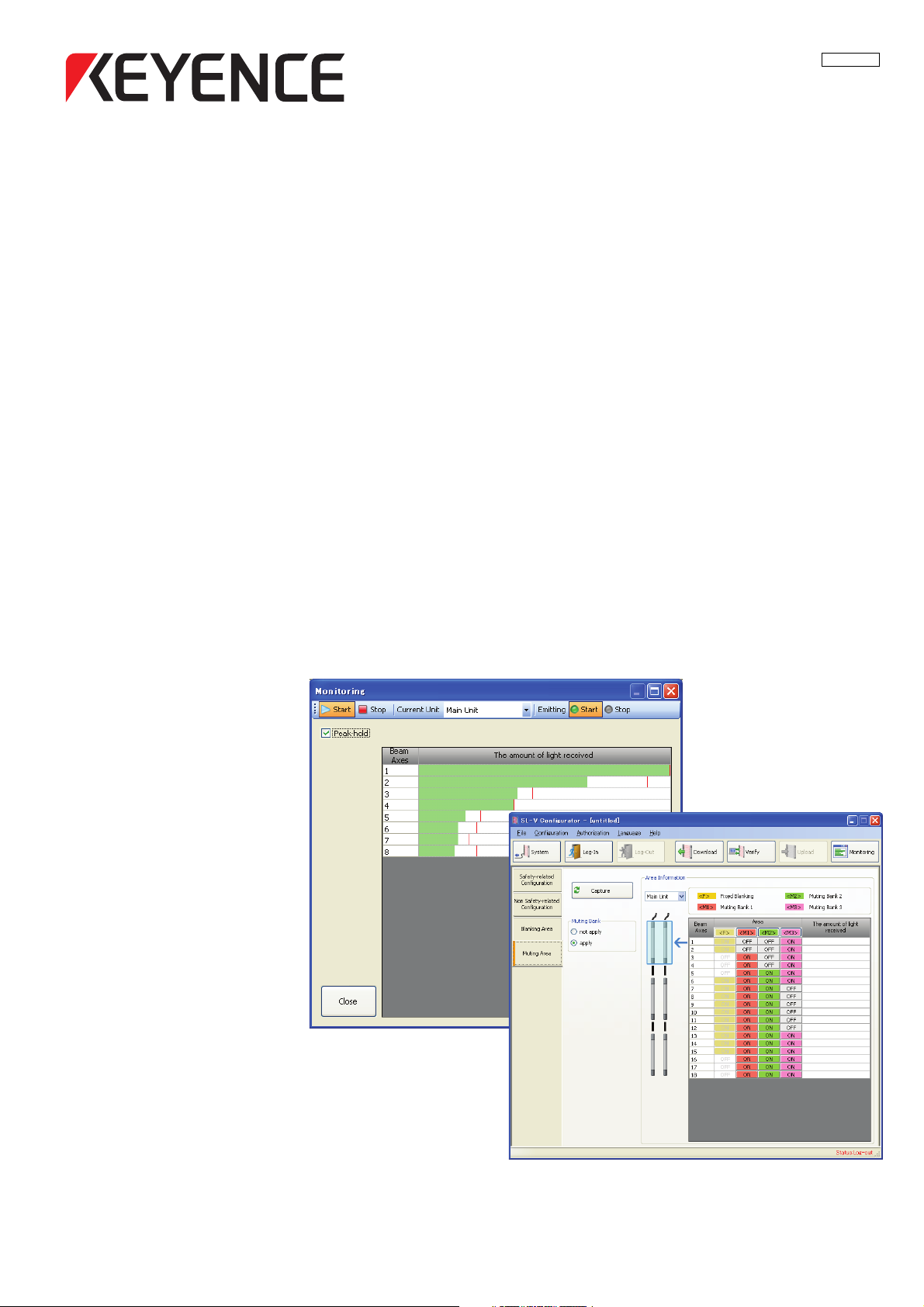
1 Click [Monitoring] on the toolbar.
The received light intensity for each light axis is displayed.
Other Functions
Item Function
(1) Start Starts monitoring the received light intensity.
(2) Stop Pauses monitoring the received light intensity.
(3) Current Unit
(4) Start Starts the laser emission of the SL-V.
(5) Stop Stops the laser emission of the SL-V.
(6) Peak-hold When the checkbox is selected, the line that shows the peak value of the
(7) Received light intensity
monitor area
(8) Peak Value
(9) Close Closes the received light intensity monitoring screen.
Reference
It is recommended that the SL-V is installed so that the bars for the received light intensity of all the beam
axis numbers reach the limit.
When a subunit is connected, this switches between Main Unit, Sub Unit 1, and Sub Unit 2.
receiving light is displayed.
The received light intensity for each beam axis is displayed by bars.
When the [Peak-hold] is selected, the peak value of the received light intensity is displayed.
2 Click the [Close] button.
The monitoring screen closes, and the screen returns to the setting screen.
SL-VH1S-NO4-E
4-7
Page 46

4
4-6 Changing the Password
Important
NOTE
NOTE
The password used when uploading settings to the connected SL-V or initializing settings can be
changed.
Be sure to keep the password in a safe place and do not forget it.
If you forget the password, configuration cannot be uploaded, initialized, or changed.
Other Functions
• The password can be changed only when the SL-V is connected and you are logged in.
"2-6 Login/Logout" (Page 2-10)
• The password is the same as the one that is set using the input line of the SL-V.
1 Select [Change Password(P)] from the [Authorization(R)] menu.
The [Password change] dialog box appears.
2 Enter the new password as four single-byte numbers.
Enter the same password in the [New PassWord(Confirmation)].
"0000" cannot be set as a password.
3 Click [OK].
The password is changed.
4-8
SL-VH1S-NO4-E
Page 47

4
4-7 Initializing the SL-V
NOTE
NOTE
The connected SL-V can be initialized by uploading the factory default settings to the unit.
• Settings can be initialized only when the SL-V is connected and you are logged in.
"2-6 Login/Logout" (Page 2-10)
• The password setting will not be changed.
1 Select [Restore to Factory Settings] from the [Configuration].
The [Warning] dialog box appears.
2 Click [OK].
Other Functions
When the settings have been changed, the save confirmation dialog box appears.
When you want to save the settings, click [Yes] to save the configuration file. When the [No]
button is clicked, the settings will be cleared without saving.
The first page of the [Upload] dialog box appears. (The factory default settings are uploaded.)
SL-VH1S-NO4-E
4-9
Page 48

4-7 Initializing the SL-V
4
Important
3 Click the [Next] button.
The second page of the [Upload] dialog box appears. (The factory default settings are uploaded.)
Other Functions
Be sure to check the settings to be uploaded before clicking the [Accept] button. When
unexpected settings are displayed, click the [Not Accept] button.
When the [Not Accept] button is clicked, configurations are not set on the SL-V and the SL-V will
not be started (It will go to lockout condition). To restore the SL-V, upload must be completed
once.
4 Click the [Accept] button.
The [Warning] dialog box appears.
5 Click the [OK] button.
The initial reset is completed.
4-10
SL-VH1S-NO4-E
Page 49

4
4-8 Outputting the Settings
Settings can be output to paper or files so that they can be checked.
Printing
Perform the following procedures to print the settings.
1 Select [Print] from the [File] menu.
The [Print] dialog box appears.
Item Function
Select Printer Name
Paper Options Paper Size* Sets the size of the paper.
Copies Specifies the number of copies to print. Setting range: 1 to 999
Print Preview Previews the print.
*
Preference
Orientation Sets the orientation of the paper.
Specifies the printer to be used.
*
Sets the advanced settings for the printer.
Other Functions
Print Starts printing.
Cancel Stops printing.
* The displayed settings differ depending on the printer.
2 Set the print settings and click the [Print] button.
Printing starts.
Reference
The following items will be printed.
SL-VH1S-NO4-E
4-11
Page 50

4-8 Outputting the Settings
4
Other Functions
Outputting in the CSV format
To output the settings in CSV format, perform the following procedures.
1 Select [Export CSV File] from the [File] menu.
The [Save As] dialog box appears.
2 Enter the file name and press the [Save] button.
The CSV file is saved in the directory specified in the [Save in].
4-12
SL-VH1S-NO4-E
Page 51

A
Appendix
A-1 Error Messages . . . . . . . . . . . . . . . . . . . . . . . . . . . . . . . . . . . . A-2
A-2 Operation Menu List . . . . . . . . . . . . . . . . . . . . . . . . . . . . . . . . A-3
A-3 Index . . . . . . . . . . . . . . . . . . . . . . . . . . . . . . . . . . . . . . . . . . . . A-4
SL-VH1S-NOA-E
A-1
Page 52

A
A-1 Error Messages
This section describes major error messages displayed during operations and the remedies when the
messages are displayed.
Error message Cause Remedy
Current SL-V system information mismatches
the last upload settings.
The last uploaded settings will be downloaded
or be verified with. Continue?
The amount of light received is not correctly
Appendix
shown due to the unit mismatch.
Monitoring cannot be done due to the main-unit
mismatch.
Units mismatch. The system information on the SL-V
SL-V doesn't have an initial Password. A password has already been set on
The system information sent to the
SL-V main unit and the actual
configuration of the SL-V is different.
•
The transmitter is not connected.
•
The transmitter and receiver are not
the same model.
The type and the number of beam
axes from the connected SL-V Series
(main unit) are different from the
settings of the main unit on the SL-V
Configurator.
Configurator differs from the
information for the SL-V.
the SL-V.
Check the configuration
of the SL-V.
•
Connect a transmitter.
•
Connect a transmitter
and receiver of the
same model.
Conform the settings of
the main unit on the SL-V
Configurator to the
settings on the SL-V.
Conform the system
information on the SL-V
Configurator to the
configuration of the SL-V.
When you want to change
the password, refer to
"4-6 Changing the
Password" (Page 4-8). (If
you forget the password,
it cannot be changed.)
A-2
SL-VH1S-NOA-E
Page 53

A
A-2 Operation Menu List
File (F)
Item Description
New (N) Creates new settings. [Shortcut key: Ctrl + N]
Open (O) Opens the saved configuration file. [Shortcut key: Ctrl + O]
Save (S) Saves the current settings over the old ones. [Shortcut key: Ctrl + S]
Save As (A) Saves the current settings as a new file.
Export CSV File (V) Outputs the current settings as a CSV format file.
System Information (U) Changes the type information.
Print (P) Prints the current settings.
Exit (X) Exits the SL-V Configurator.
Configuration (C)
Item Description
Download from SL-V (R) Reads settings from the SL-V.
Upload to SL-V (W) Writes the settings into the SL-V.
Verify (V) Verifies settings with the settings of the SL-V.
Monitoring (M) Monitors the amount of received light intensity of the SL-V.
Restore to Factory Settings (I)
Initializes the settings of the SL-V.
Reference
page
2-6
2-13
2-7
2-13
4-12
4-3
4-11
2-7
Reference
page
2-5
2-11
4-6
4-7
4-9
Appendix
Authorization (R)
Item Description
Log-In (I) Logs in to the SL-V.
Log-Out (O) Logs out from the SL-V.
Change Password (P) Changes the password that is already set.
Init Password (S) Sets a new password when a password is not previously set.
Language (L)
Item Description
Japanese (J) Displays in Japanese.
English (E) Displays in English.
Help (H)
Item Description
View Help (H) Displays the manual. [Shortcut key: F1]
About SL-V Configurator (V) Displays the version information of the software.
Reference
page
2-10
2-10
4-8
2-9
Reference
page
−
−
Reference
page
−
−
SL-VH1S-NOA-E
A-3
Page 54

A
A-3 Index
This index provides a list of terms used in this document. It is arranged in alphabetic order.
A
Alert Output ...................................................... 3-4
Appendix
Authorization (R)
.......................................................... A-1
............................................... A-3
B
Appendix
Basic Operation ............................................... 2-1
Before Use
Blanking Area
....................................................... 1-1
................................................... 3-6
C
Center Indicator ............................................... 3-5
Changing the Password
Changing the Type Configuration
Checking Package Contents
Configuration (C)
.............................................. A-3
Configuration of Each Function
Configuration Tab
Configuring the Functions
Connecting
....................................................... 1-8
Connecting the SL-V and the Computer
Creating New Settings
Creating the Configuration on the PC
................................... 4-8
.................... 4-3
........................... 1-2
........................ 3-1
............................................. 2-3
................................ 2-8
.......... 1-7
..................................... 4-2
.............. 2-4
E
Installing the <SL-V Configurator>
Installing to a Windows machine
Interlock Configuration
..................................... 3-3
L
Language (L) ....................................................A-3
Loading Configurations from the SL-V
Logging In
Logging Out
Login/Logout
...................................................... 2-10
................................................... 2-10
.................................................. 2-10
M
Menu Bar .......................................................... 2-2
Monitoring the Received Light Intensity on
the SL-V
Muting Area
Muting Configuration
......................................................... 4-7
...................................................... 3-7
........................................ 3-2
N
Names and Functions of SL-V1UB Interface
Unit Parts
Names of Parts in Main Window
Non Safety Related Configuration
Notes for Windows Vista/7
Notes for Windows XP
....................................................... 1-7
............................... 1-5
...................................... 1-5
................... 1-5
...................... 1-5
............. 4-5
...................... 2-2
.................... 3-4
EDM Function / Adjustment .............................. 3-3
Emitting Frequency
Error Messages
Exiting the <SL-V Configurator>
.......................................... 3-4
................................................ A-2
...................... 2-7
F
File (F) .............................................................. A-3
Flow of Basic Operation
Function Configuration Area
................................... 2-4
............................ 2-3
H
Hard disk space ............................................... 1-5
Help (H)
Help files
............................................................ A-3
.......................................................... 1-5
I
Initializing the SL-V ........................................... 4-9
Installation
Installation CD-ROM
........................................................ 1-6
......................................... 1-2
O
Opening an Existing Configuration ................ 2-13
Operation Menu List
Other Functions
Outputting in the CSV format
Outputting the Settings
Override Function
.........................................A-3
................................................ 4-1
......................... 4-12
.................................. 4-11
............................................. 3-2
P
Preparation ....................................................... 1-5
Printing
........................................................... 4-11
S
Safety Related Configuration ........................... 3-2
Saving and Using the Configuration on
the PC
.......................................................... 2-13
Saving the Configuration
Setup of the Password
SL-V Configurator Installation folder
Startup and Exiting the <SL-V Configurator>
................................ 2-13
..................................... 2-9
................. 1-6
.. 2-5
A-4
SL-VH1S-NOA-E
Page 55

A
Startup of the <SL-V Configurator> ................. 2-5
State Information Output
Status Bar
......................................................... 2-3
System Requirements
.................................. 3-4
...................................... 1-4
T
To read the existing configuration file .............. 2-7
To ol b ar
.............................................................. 2-2
U
Uninstalling the <SL-V Configurator> .............. 1-6
Uploading the Configuration to the SL-V
USB port
User privileges (Vista/7)
User privileges (XP)
Using the Configurator
........................................................... 1-5
................................... 1-5
......................................... 1-5
..................................... 1-3
.2-4, 2-11
A-3 Index
Appendix
V
Verifying the Configuration between PC
and SL-V
....................................................... 4-6
W
When "Create New Configuration" is selected .2-6
When "Download from SL-V" is selected
.......... 2-5
SL-VH1S-NOA-E
A-5
Page 56

A-3 Index
A
MEMO
Appendix
A-6
SL-VH1S-NOA-E
Page 57

A
MEMO
A-3 Index
Appendix
SL-VH1S-NOA-E
A-7
Page 58

Revision History
Date Revision Revision contents
November 2008 First
December 2008 Second Notes added in "Connecting", etc.
June 2009 Third Values changed in "EDM Function / Adjustment", etc.
June 2010 Fourth Descriptions of "Windows 7 compatible" added, etc.
September 2014 Fifth
Page 59

WARRANTY
KEYENCE products are strictly factory-inspected. However, in the event of a failure, contact your nearest KEYENCE office
with details of the failure.
1. WARRANTY PERIOD
The warranty period shall be for one year from the date that the product has been delivered to the location specified
by the purchaser.
2. WARRANTY SCOPE
(1) If a failure attributable to KEYENCE occurs within the above mentioned warranty period, we will repair the product, free
of charge. However, the following cases shall be excluded from the warranty scope.
• Any failure resulting from improper conditions, improper environments, improper handling, or improper usage other
than described in the instruction manual, the user’s manual, or the specifications specifically arranged between the
purchaser and KEYENCE.
• Any failure resulting from factors other than a defect of our product, such as the purchaser’s equipment or the
design of the purchaser’s software.
• Any failure resulting from modifications or repairs carried out by any person other than KEYENCE staff.
• Any failure that can certainly be prevented when the expendable part(s) is maintained or replaced correctly as
described in the instruction manual, the user’s manual, etc.
• Any failure caused by a factor that cannot be foreseen at a scientific/technical level at the time when the product
has been shipped from KEYENCE.
• Any disaster such as fire, earthquake, and flood, or any other external factor, such as abnormal voltage, for which
we are not liable.
(2) The warranty scope is limited to the extent set forth in item (1), and KEYENCE assumes no liability for any purchaser’s
secondary damage (damage of equipment, loss of opportunities, loss of profits, etc.) or any other damage resulting
from a failure of our product.
3. PRODUCT APPLICABILITY
KEYENCE products are designed and manufactured as general-purpose products for general industries.
Therefore, our products are not intended for the applications below and are not applicable to them. If, however, the
purchaser consults with us in advance regarding the employment of our product, understands the specifications,
ratings, and performance of the product on their own responsibility, and takes necessary safety measures, the
product may be applied. In this case, the warranty scope shall be the same as above.
• Facilities where the product may greatly affect human life or property, such as nuclear power plants, aviation,
railroads, ships, motor vehicles, or medical equipment
• Public utilities such as electricity, gas, or water services
• Usage outdoors, under similar conditions or in similar environments
Page 60

Copyright (c) 2008 KEYENCE CORPORATION. All rights reserved. 96008E 1094-5 96008E Printed in Japan
 Loading...