

Page 1
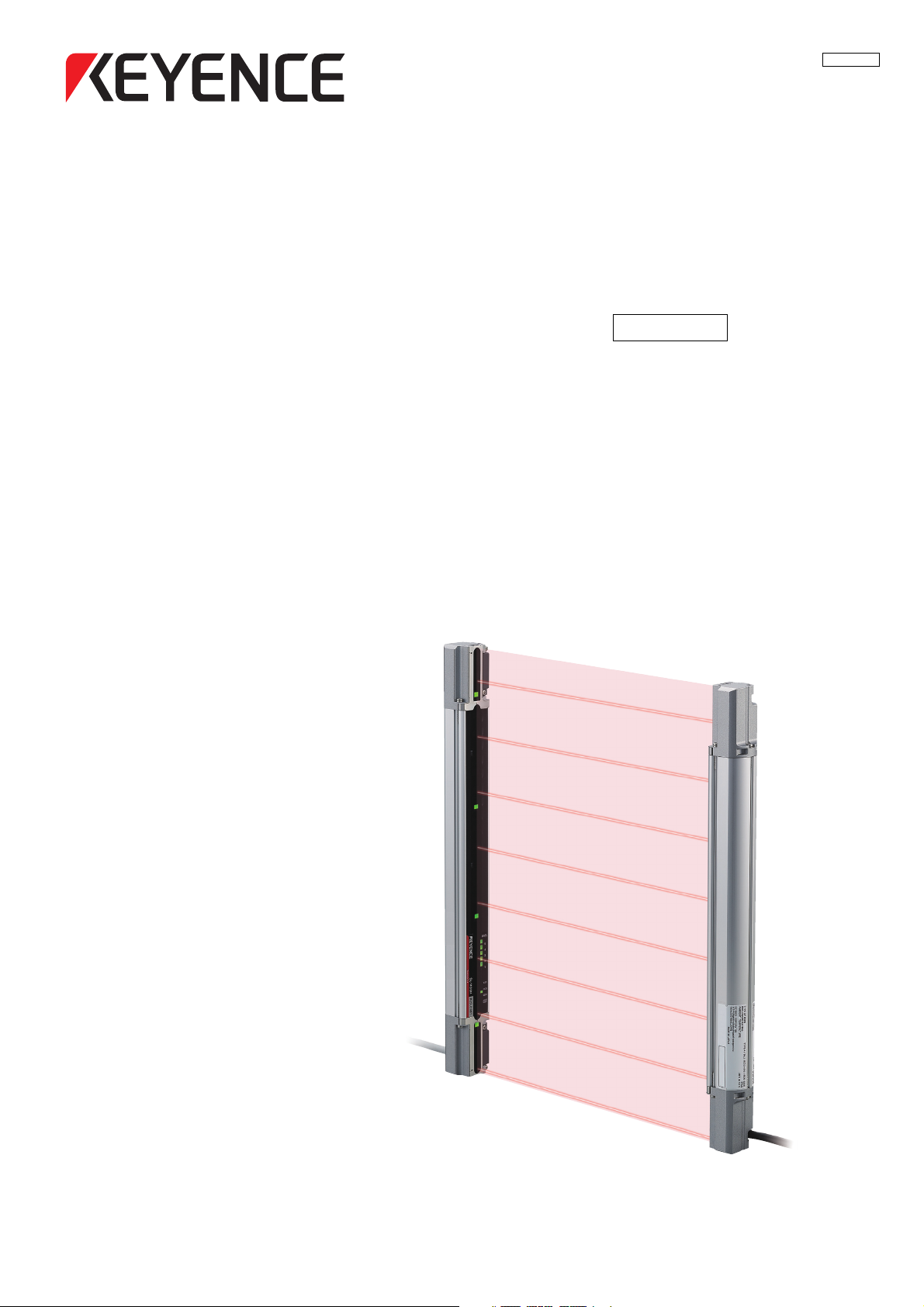
Safety Light Curtain
96007E
SL-V Series
Version 3.0
User’s Manual
Page 2
Introduction
Danger
Caution
NOTE
Reference
This user’s manual describes handling, operation, and precautionary information for the SL-V Series
Safety Light Curtain ("SL-V").
Read this user’s manual thoroughly before operating the SL-V in order to understand the device features,
and keep this user’s manual readily available for reference. Ensure that the end user of this product
receives this manual.
In this user’s manual, "SL-VF" represents the finger protection type with the detection capability of 14
mm, "SL-VH" represents the hand protection type with the detection capability of 25 mm, "SL-VL" represents the body protection type with the detection capability of 45 mm, "SL-VFM" represents the finger
protection and rigid enclosure type with the detection capability of 14 mm, "SL-VHM" represents the
hand protection and rigid enclosure type with the detection capability of 25 mm, "SL-VLM" represents
the body protection and rigid enclosure type with the detection capability of 45 mm, and "SL-V" represents all the models including the SL-VF, SL-VH, SL-VL, SL-VFM, SL-VHM, and SL-VLM.
See "Model" (page 7-2).
Safety headings
This user’s manual uses the following headings to display important safety information. Strict adherence
to the instructions next to these heading is required at all times.
Failure to follow the instruction results in significant harm to the machine operators including
serious injury or death.
Failure to follow the instruction may result in damage to the SL-V or to the machine on which it
is installed.
Provides additional information for proper operation.
Provides advanced and useful information for operation.
Indicates reference pages in this or another manual.
Page 3

Safety Precautions
General precautions
• You must verify that the SL-V is operating correctly in terms of functionality and performance before the
start of machine and the operation of the SL-V.
• KEYENCE does not guarantee the function or performance of the SL-V if it is used in a manner that differs from the SL-V specifications contained in this user’s manual or if the SL-V is modified by the customer.
• When using the SL-V to protect machine operators against a hazard or hazardous zone or using the
SL-V as a safety component for any purpose, always follow the applicable requirements of the laws,
rules, regulations and standards in the country or region where the SL-V is used. For such regulations,
you should contact directly to the regulatory agency responsible for occupational safety and health in
your country or region.
• Depending on the type of machine on which the SL-V is to be installed, there may be special safety
regulations related to the use, installation, maintenance, and operation of the safety component. In
such a case, you must fulfill such safety regulation. The responsible personnel must install the SL-V in
strict compliance with such safety regulations.
• The responsible personnel must do the training to the assigned personnel for the correct use, installation, maintenance, and operation of the SL-V. "Machine operators" refers to personnel who have
received appropriate training from the responsible personnel and are qualified to operate the machine
correctly.
• Machine operators must have specialized training for the SL-V, and they must understand and fulfill the
safety regulations in the country or region in which they are using the SL-V.
• When the SL-V fails to operate, machine operators must immediately stop the use of the machine and
the SL-V and report this fact to the responsible personnel.
• The SL-V is designed with the assumption that it would be correctly installed in accordance with the
installation procedures described in this user’s manual and correctly operated according to the instructions in this user’s manual. You must perform an appropriate installation of the SL-V after performing a
sufficient risk assessment for the target machine.
• The SL-V should be processed as an industrial waste product when being disposed.
SL-V-M-NO0-E
96007E
1
Page 4
Precaution on use
Danger
Danger
Danger
Operators
• In order to operate the SL-V correctly, the responsible personnel and machine operators
• No person other than the responsible personnel and machine operators should be allowed
• When performing electrical wiring, always fulfill the electrical standards and regulations for
Environment of use
• Do not use the SL-V in an environment (temperature, humidity, interfering light, etc.) that
•
• The SL-V is not designed to be explosion-proof. Never use it in the presence of flammable
• Be sure to confirm no deterioration in product quality if you use the SL-V in the presence of
• Do not install the SL-V in areas where the SL-V is exposed to intense interference light such
•
• Be sure to absolutely confirm that there is nobody in the hazardous zone, before the over-
must fulfill all of the procedures described in this user’s manual.
to install or test the SL-V.
the country or region in which the SL-V is used.
does not conform to the specifications contained in this user’s manual.
Be sure to confirm that the SL-V keeps normal operation when electromagnetic radiation is
generated by wireless devices. (If you use wireless devices such as cellular phones or transceivers in the vicinity of the SL-V.)
or explosive gases or elements.
substances, such as heavy smoke, particulate matter, or corrosive chemical agents.
as direct sunlight, and direct or indirect light from inverter-type fluorescent lamp (rapid-start
type lamp, high-frequency operation type lamp, etc).
Be sure to absolutely confirm that there is nobody in the hazardous zone, before the interlock is
released (i.e. the machine system restarts) by the interlock reset mechanism. Failure to follow this
warning results in a significant harm to the machine operators, including serious injury or death.
ride function is activated. Failure to follow this warning results in a significant harm to the
machine operators, including serious injury or death.
Target machine
2
• The SL-V has not undergone the model certification examination in accordance with Article
44-2 of the Japanese Industrial Safety and Health Law. The SL-V, therefore, cannot be used
in Japan as a “Safety Device for Press and Shearing machines” as established in Article 42
of that law.
The machine on which the SL-V is to be installed must be susceptible to an emergency stop at all
•
operating points during its operation cycle. Do not use the SL-V for machines with irregular stop times.
• Do not use the SL-V for power presses equipped with full-revolution clutches.
• The SL-V cannot be used as a PSDI because it does not fulfill the requirements of OSHA
1910.217(h). Refer to OSHA 1910.217 for the PSDI mode.
• Do not use the SL-V to control (stop forward motion, etc.) trains, cars and other transportation vehicles, aircraft, equipment for use in space, medical devices, or nuclear power generation systems.
• The SL-V is designed to protect the people or objects from going into/approaching detection zone against machine’s hazard or hazardous zone. It cannot provide protection against
objects or materials that are expelled from the machine’s hazard or hazardous zone, so you
must establish additional safety measures such as installing safeguards when there is the
possibility of such projectiles.
SL-V-M-NO0-E
Page 5

Installation
Danger
• The SL-V must be installed only after ensuring the minimum safety distance between the
SL-V and the hazardous zone or hazard as established by the applicable regulations in the
country or region in which the SL-V is used. (e.g.EN ISO13855(ISO 13855)in EU countries)
• Choose locations for the installation of the SL-V transmitters and receivers so that they are
not subject to the effects of light reflected from glossy surfaces in the area.
• Correct operation and detection is not possible if the receiver has a different number of
beam axes from that of the transmitter. You must verify that the number of beam axes is the
same between the transmitter and the receiver when installing the SL-V.
• Correct operation and detection is not possible if the receiver has a different beam axis
spacing (detection capability) from that of the transmitter. You must verify that the beam axis
spacing (detection capability) is the same between the transmitter and the receiver when
installing the SL-V.
• The SL-V must be installed so that the machine operator is able to go into or approach the
hazardous zone or hazards only by passing through the detection zone of the SL-V. Strictly
avoid installation that allows the machine operator or a part of the machine operator's body
to go into or approach the hazardous zone or hazards without passing through the detection zone of the SL-V or to remain in a position between the detection zone of the SL-V and
the hazardous zone or hazard. In case where you install the SL-V units in series (series
connection), you always must check the installation carefully whether you follow this warning, especially after installation and maintenance.
Even if you forget to install the SL-V unit to be connected in series, or if the series connection cable is disconnected, the SL-V does not detect such a missing or disconnection. (It
means the SL-V starts the normal operation.) This causes a dangerous situation because
there is no protection at the area to be protected.
• You must always perform the pre-check tests after installing the SL-V in accordance with
the pre-check test procedures, such as items specified in this user’s manual, in order to verify that the test pieces can be detected in all of the detection zones.
• Interlock reset mechanisms (such as switches) must be installed so that the whole hazardous zone can be checked by the responsible personnel. Interlock reset mechanisms should
not be accessible from within the hazardous zone.
• Muting is a function to allow a temporary automatic suspension of the SL-V safety functions
while the SL-V is receiving a signal from muting devices (such as sensors or switches).
Therefore, additional safety measures are required for the machine on which the SL-V is
installed in order to ensure safety while the muting is activated.
• Muting devices, the installation of those devices and the procedure to activate the muting
function must fulfill the conditions specified in this user’s manual and the requirements of
the laws, rules, regulations and standards in the country or region in which the SL-V and
those devices are used. Failure to follow this warning may result in significant harm to the
machine operators, including serious injury or death.
• When you install muting devices (such as sensors or switches) for muting, the following
conditions must be fulfilled.
(1) Muting devices must be installed so that the muting cannot be activated if the
hazardous zone of the machine is in an unsafe condition or cycle.
(2) Muting devices must be installed so that the muting cannot be activated even if the
personnel is accidentally approaching the detection zone of the SL-V.
•
The muting device must be installed such that only responsible personnel have access to that
device to change its installation or orientation. Special tools must be required to ensure that only
responsible personnel are capable of installation, orientation or change of muting device.
• Only the responsible personnel may be allowed to install or wire the devices to activate the
muting function.
SL-V-M-NO0-E
3
Page 6

• The installation of muting lamp may be required by the laws, rules, regulations, and stan-
Danger
dards in the country or region in which the SL-V is used if you apply the muting function. It
depends on the machine application and/or the result of your risk assessment. If it is necessary for you to provide the muting lamp, you must fulfill the requirements because you are
fully responsible for installation of muting lamp.
•
When the reduced resolution function is applied, the detection capability varies according to
your configuration. Make sure to accurately calculate the safety distance according to the
detection capability, and install the SL-V at a distance greater than or equal to the minimum
safety distance away from the hazardous zone or hazard. The installation of additional safety
measures, such as a safeguarding, may be required if the detection capability varies due to the
configuration of the reduced resolution function. On your own responsibility, you must perform
the risk assessment based on your configuration of the reduced resolution function in order to
reduce the risk.
• When the fixed blanking function is applied, a hazardous clearance that is not protected by
the SL-V may be generated between the obstacle and the SL-V. You must install an additional safety measure such as a safeguard for this clearance.
• The override is a function to allow a temporary manual suspension of the safety functions of
the SL-V. Therefore, additional safety measures are required for the whole machine system
on which the SL-V is installed in order to ensure safety while the override is activated.
• The override devices, the installation of those devices and the procedures to activate the
override must fulfill the conditions specified in this manual as well as the requirements of the
laws, rules, regulations and standards in the country or region in which the SL-V and those
devices are used. Failure to follow this warning may result in significant harm to the
machine operators, including serious injury or death.
• The override devices, which are used for activation of override, must be manual operating
device. When installing the devices to activate the override, those devices must be installed
so that the whole hazardous zone can be checked by the responsible personnel and so that
it is not possible for machine operators to operate those devices in the hazardous zone.
• The installation of the indication for override may be required by the laws, rules, regulations,
and standards in the country or region in which the SL-V is used if you apply the override
function. It depends on the machine application and/or the result of your risk assessment. If
it is necessary for you to provide the indication for override, you must fulfill the requirements
because you are fully responsible for installation of the indication for override.
• The customer is fully responsible for complying with the requirements for the muting and/or
override. Those who use muting and/or override must fulfill all of the requirements related to
muting and/or override. KEYENCE accepts NO responsibility or NO liability for any damage
or any injury due to the unauthorized installation, usage or maintenance, which are not
specified in this user’s manual, and/or due to noncompliance with the laws, rules, regulations and standards in the country or region in which the SL-V is used.
• Securely tighten mounting brackets and cable connectors used for the installation of the SLV in accordance with the torque values specified in this user’s manual.
Circuit design and wiring
4
• Always turn off the power to the SL-V when performing electrical wiring.
• You must fulfill the electrical standards and regulations in the country or region in which the
SL-V is being used when you perform the electrical wiring.
• To avoid the risk of electric shock, do not connect any of the SL-V inputs to DC power
sources outside of the range of 24 V DC + 10% or to any AC power source.
• To avoid the risk of electric shock, be sure that the hazardous voltage is isolated from all
wiring of the SL-V with reinforced insulation or double insulation.
SL-V-M-NO0-E
Page 7

• In order to fulfill the requirements in IEC61496-1, UL61496-1, EN61496-1 and UL508,
power supply for the SL-V must fulfill the conditions listed below.
(a) A rated output voltage of 24 V DC (SELV, Overvoltage Category II) within +10% and -20%.
(b) Double insulation or reinforced insulation between the primary and secondary circuits.
(c) Output holding time of 20 ms or more.
(d) A power supply must fulfill the requirements of the electrical safety and electromagnetic
compatibility (EMC) regulations or standards in all countries and/or regions where the
SL-V is used.
(e) A secondary circuit of power supply (output) must fulfill the requirements for Class 2
Circuits or Limited Voltage/Current Circuits specified in UL508, if the SL-V is used in
the United States or Canada.
• Do not install the electric wiring of the SL-V together with or in parallel with high-voltage
electrical or power lines.
• Both OSSD outputs provided on the SL-V must be used to establish a safety-related
machine control system. Establishing a safety-related machine control system with just one
of the OSSD outputs cannot stop the machine due to an OSSD output malfunction and may
result in significant harm to the machine operators, including serious injury or death.
•
When using a PNP output type cable, do not cause short-circuit between the OSSD and +24V.
Otherwise, the OSSDs keep staying at the ON-state and it causes a dangerous situation.
•
When using a PNP output type cable, be sure to connect the load between the OSSD and 0V to
avoid a dangerous situation. If the load is incorrectly connected between the OSSD and +24V,
the logic of the OSSD operation will be reversed and the OSSD will change to an ON state when
the SL-V detects the interruption in the detection zone. This is a dangerous situation.
• When using NPN output type cables, do not cause short-circuit between the OSSD and 0V.
Otherwise, the OSSDs keep staying at the ON-state and it causes a dangerous situation.
•
When using an NPN output type cable, be sure to connect the load between the OSSD and
+24V to avoid a dangerous situation. If the load is incorrectly connected between the OSSD and
0V, the logic of the OSSD operation will be reversed and the OSSD will change to an ON state
when the SL-V detects the interruption in the detection zone. This is a dangerous situation.
• In case of wiring, regardless of PNP or NPN output type cables, you must fulfill the requirements of Clause 9.4.3 in IEC60204-1: 2005 in order for the protection against maloperation
due to earth fault.
• The Alert output, AUX output, Clear/Blocked Output, state information output and interlockreset-ready output are not allowed to be used as safety outputs for safety-related machine
control systems. Usage of these functions as safety outputs may result in a significant harm
to the machine operators, including serious injury or death.
• The wait input is not allowed to be connected to the output from any components comprising a part of the safety-related machine control system. If the wait input is connected to the
output of a safety component it may result in a significant harm to the machine operators,
including serious injury or death.
• The transmitter and receiver cables must be within the lengths specified in this user’s manual. Usage of cables longer than the specified length may cause the improper operation of
safety functions and may cause a dangerous situation.
Testing and maintenance
• You must always perform the pre-check test in accordance with the pre-check test procedures, after
maintenance, adjustment or alignment of the target machine or the SL-V and before the machine startup.
• If the SL-V does not operate properly when you perform pre-check test in accordance with the precheck test procedures specified in this user’s manual, do not operate the machine.
• You must periodically examine the machine to verify that all brakes, other stop mechanisms, and control devices operate reliably and correctly in addition to checking the SL-V.
• The responsible personnel must perform maintenance procedures as specified in this user’s manual to
ensure safety to the machine and SL-V.
SL-V-M-NO0-E
5
Page 8

Standards and regulations
1 The SL-V is a "Safety Part" specified in the EU Machinery Directive (2006/42/EC) Annex V.
The SL-V complies with the following EU Directives and EN Standards and has been certified by TÜV
SÜD Product Service GmbH.
EU Directives
• Machinery Directive (2006/42/EC)
• EMC Directive (2004/108/EC)
EN Standards
• EN61496-1 Type 4 ESPE
• EN61496-2 Type 4 AOPD
• EN55011 ClassA
• EN50178
• EN61508, Part 1 to 4 SIL3
• EN62061 SIL3
• EN ISO13849-1 Category 4, PLe
2 The SL-V complies with the following UL (Underwriters Laboratories Inc.) and IEC standards and has
been certified by UL. (CCN :NIPF/NIPF7)
• UL61496-1 Type 4 ESPE
• UL61496-2 Type 4 AOPD
• UL508
• UL1998
The SL-V also complies with the following regulations.
• FCC Part 15B Class A Digital Device
• ICES-003 Class A Digital Apparatus
3 The SL-V has not obtained the model certification examination in accordance with Article 44-2 of the
Japanese Industrial Safety and Health Law. Therefore, the SL-V cannot be used in Japan as a "Safety
Devices for Presses and Shearing Machines" as established in Article 42 of that law.
The SL-V has been designed in consideration of the following standards and regulations. For details
4
regarding the following standards, contact the third-party certification organization, such as UL or TÜV.
Corresponding standards
• EN60204-1
•EN692
•EN693
• OSHA 29 CFR 1910.212
• OSHA 29 CFR 1910.217
• ANSI B11.1 - B.11.19
• ANSI/RIA R15.06 - 1999
• SEMI S2
• "Guidelines for Comprehensive Safety Standards of Machinery", July 31, 2007, number 0731001
issued by Ministry of Health, Labor, and Welfare in Japan.
6
SL-V-M-NO0-E
Page 9

Table of Contents
Introduction
Safety headings
Safety Precautions .................................................................................................................. 1
General precautions................................................................................................................1
Precaution on use ................................................................................................................... 2
Testing and maintenance........................................................................................................ 5
Standards and regulations......................................................................................................6
Table of Contents .................................................................................................................... 7
Chapter 1 Before Use
1-1 Checking the Package Contents ................................................................................ 1-2
Standard set.........................................................................................................................1-2
1-2 Options ....................................................................................................................... 1-3
Mounting brackets (For SL-VF/VH/VL) .................................................................................1-3
Mounting brackets (For SL-VFM/VHM/VLM) ........................................................................1-3
Cables ..................................................................................................................................1-4
Protection bar.......................................................................................................................1-7
Front protection cover and dimmer filter ..............................................................................1-8
SL-V Configurator (SL-VH1S) ...............................................................................................1-8
1-3 Part Description........................................................................................................ 1-10
SL-V main unit ....................................................................................................................1-10
With options installed .........................................................................................................1-10
Chapter 2 Functions and Features
2-1 Cable Selection and Function .................................................................................... 2-2
Functions..............................................................................................................................2-2
Cable color and pin assignment ..........................................................................................2-3
2-2 Self-diagnosis Function .............................................................................................. 2-4
Lockout condition.................................................................................................................2-4
OSSD....................................................................................................................................2-5
2-3 Series Connection ...................................................................................................... 2-6
2-4 Interlock Function ....................................................................................................... 2-7
Automatic start / Automatic reset mode...............................................................................2-8
Other than Automatic start / Automatic reset mode...........................................................2-10
2-5 AUX (Auxiliary) Output ............................................................................................. 2-14
2-6 External Device Monitoring (EDM Function) ............................................................ 2-15
2-7 Wait Input Function................................................................................................... 2-16
2-8 State Information Output .......................................................................................... 2-18
2-9 Alert Output .............................................................................................................. 2-25
2-10 Clear/Blocked Output ............................................................................................... 2-27
SL-V-M-NO0-E
7
Page 10

2-11 Temporary Suspension of Safety Function............................................................... 2-29
Muting function...................................................................................................................2-29
Changing configuration of the muting function..................................................................2-33
Override function................................................................................................................2-45
Override Function Settings.................................................................................................2-47
2-12 Fixed Blanking.......................................................................................................... 2-48
2-13 Reduced Resolution ................................................................................................. 2-49
2-14 I/O Monitoring Function ............................................................................................ 2-50
Chapter 3 Installation to a Machine
3-1 Correct Installation Method ........................................................................................ 3-2
Transmitter and receiver orientation.....................................................................................3-2
Mounting position.................................................................................................................3-3
3-2 Safety Distances......................................................................................................... 3-4
3-3 Light Interference Prevention Method......................................................................... 3-8
Light Interference Prevention Function ................................................................................3-8
Series Connection ................................................................................................................3-8
Interference due to installation.............................................................................................3-8
3-4 Installation Distance from Glossy Surfaces.............................................................. 3-10
Installation distance not affected by glossy surface..........................................................3-10
3-5 Cable Connections ................................................................................................... 3-11
Cable specification ............................................................................................................3-11
Unit connection cable ........................................................................................................3-13
Series connection cable.....................................................................................................3-14
3-6 Assembling the Mounting Brackets (SL-VF/VH/VL) ................................................. 3-15
Standard mounting bracket A (OP-42347), B (OP-42348), C (OP-42349),
J (OP-83180)...................................................................................................................... 3-15
Thin type mounting bracket (OP-51698)............................................................................3-16
L-shaped mounting bracket (OP-42371) ...........................................................................3-16
Compact E-to-E mounting bracket (OP-83181).................................................................3-17
E-to-E mounting bracket (OP-42370).................................................................................3-17
Protection bar.....................................................................................................................3-18
3-7 Assembling the Mounting Brackets (SL-VFM/VHM/VLM) ........................................ 3-20
Standard mounting bracket (OP-84259)............................................................................3-20
Space-saving bracket (OP-84260) ....................................................................................3-21
3-8 System Configuration for the Muting Function ......................................................... 3-22
Example: Muting function with 2 muting devices (Sensors) ..............................................3-22
Example: Muting function with 4 of muting devices...........................................................3-25
Example: Muting function with 2 muting devices (Switches).............................................3-29
Chapter 4 Wiring
4-1 Cautions on Wiring and Power Supply ....................................................................... 4-2
8
SL-V-M-NO0-E
Page 11

Power supply........................................................................................................................4-2
4-2 I/O Circuit Diagram..................................................................................................... 4-3
4-3 Cable Color and Pin Position...................................................................................... 4-4
4-4 Examples of Wiring .................................................................................................... 4-5
Chapter 5 Optical Alignment
5-1 Optical Alignment ....................................................................................................... 5-2
Check before optical alignment...........................................................................................5-2
Alignment procedure............................................................................................................5-2
Chapter 6 Indicators
6-1 Bar LED Indicator ....................................................................................................... 6-2
Upon power-up ....................................................................................................................6-2
During normal operation ......................................................................................................6-3
6-2 Function Indicators ..................................................................................................... 6-5
6-3 Center Indicator .......................................................................................................... 6-6
Overview ..............................................................................................................................6-6
Changing the Indication Method for the Center indicator....................................................6-7
Chapter 7 Specifications and Dimensions
7-1 Model.......................................................................................................................... 7-2
Detection capability of 14 mm (0.55") Optical Axis pitch: "SL-VF" .......................................7-2
Detection capability of 14 mm (0.55") Optical Axis pitch: "SL-VFM" ....................................7-3
Detection capability of 25 mm (0.98") Optical Axis pitch: "SL-VH" ......................................7-3
Detection capability of 25 mm (0.98") Optical Axis pitch: "SL-VHM" ...................................7-4
Detection capability of 45 mm (1.77") Optical Axis pitch: "SL-VL" .......................................7-4
Detection capability of 45 mm (1.77") Optical Axis pitch: "SL-VLM" ....................................7-5
7-2 Specifications ............................................................................................................. 7-6
7-3 Response Time and Current Consumption ................................................................ 7-7
Response time (OSSD) ........................................................................................................7-7
Current consumption............................................................................................................7-8
7-4 Dimensions (SL-VF/VH/VL)........................................................................................ 7-9
SL-VF/VH/VL unit..................................................................................................................7-9
When using the standard mounting bracket, thin bracket, and L-shaped bracket ........... 7-10
When mounting only with the E-to-E bracket or the compact E-to-E bracket ....................7-12
Standard mounting bracket J (OP-83180) .........................................................................7-14
Standard mounting bracket A (OP-42347).........................................................................7-14
Standard mounting bracket B (OP-42348).........................................................................7-15
Standard mounting bracket C (OP-42349) ........................................................................7-15
Thin mounting bracket (OP-51698)....................................................................................7-16
L-shaped mounting bracket (OP-42371) ...........................................................................7-16
SL-V-M-NO0-E
9
Page 12

7-5 Dimensions (SL-VFM/VHM/VLM)............................................................................. 7-19
Appendix
A-1 Troubleshooting..........................................................................................................A-2
A-2 Checklist.....................................................................................................................A-8
Compact E-to-E mounting bracket (OP-83181).................................................................7-17
E-to-E mounting bracket (OP-42370).................................................................................7-17
Protection bar.....................................................................................................................7-18
Standard mounting bracket (OP-84259)............................................................................7-19
Space-saving bracket (OP-84260)
If the device is in the lockout condition............................................................................... A-2
If the SL-V is not in the lockout condition............................................................................ A-7
Checklist before operation .................................................................................................. A-8
................................................................................7-21
10
SL-V-M-NO0-E
Page 13

1
Before Use
1-1 Checking the Package Contents . . . . . . . . . . . . . . . . . . . . . . . 1-2
1-2 Options . . . . . . . . . . . . . . . . . . . . . . . . . . . . . . . . . . . . . . . . . . 1-3
1-3 Part Description. . . . . . . . . . . . . . . . . . . . . . . . . . . . . . . . . . . 1-10
SL-V-M-NO1-E
1-1
Page 14
1
1-1 Checking the Package Contents
• SL-V transmitter x1
• SL-V receiver x1
• Test piece x1
(Test piece with diameter of 25 mm and length of 200 mm for SL-VH,
SL-VHM, and test piece with diameter of 14mm and length of
200mm for SL-VF, VFM)
* The test piece (diameter: 45 mm) for the
SL-VL, VLM is not supplied. Please prepare by yourself.
• User’s manual x1
• Ferrite core x1 (SL-VF, VH, VL, VLM only)
x 2 (SL-VFM only)
Before Use
Standard set
LEVEL
5
4
3
2
1
SL-V08H
WAIT
FUNCTION
ø25 (0.98")
OSSD
INTER
LOCK
LEVEL
5
4
3
2
1
MUTE1
MUTE2
ø25 (0.98")SL-V08H
OSSD
INTER
LOCK
1-2
SL-V-M-NO1-E
Page 15
1
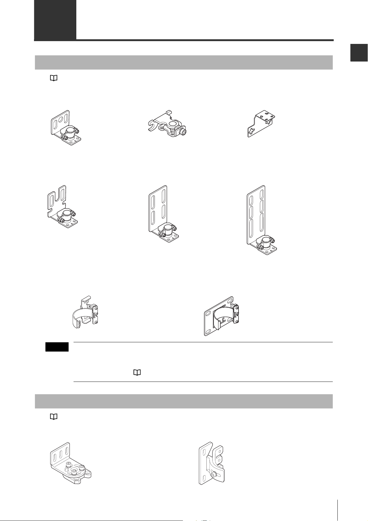
1-2 Options
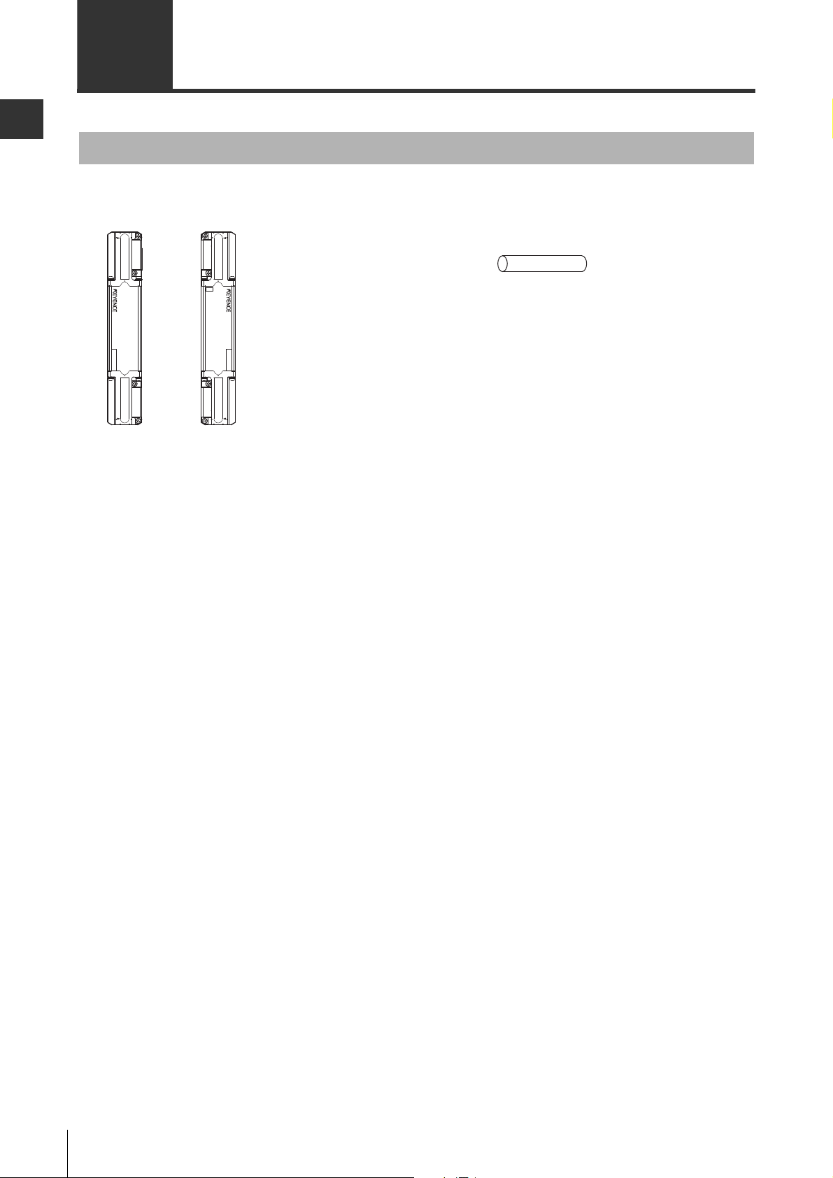
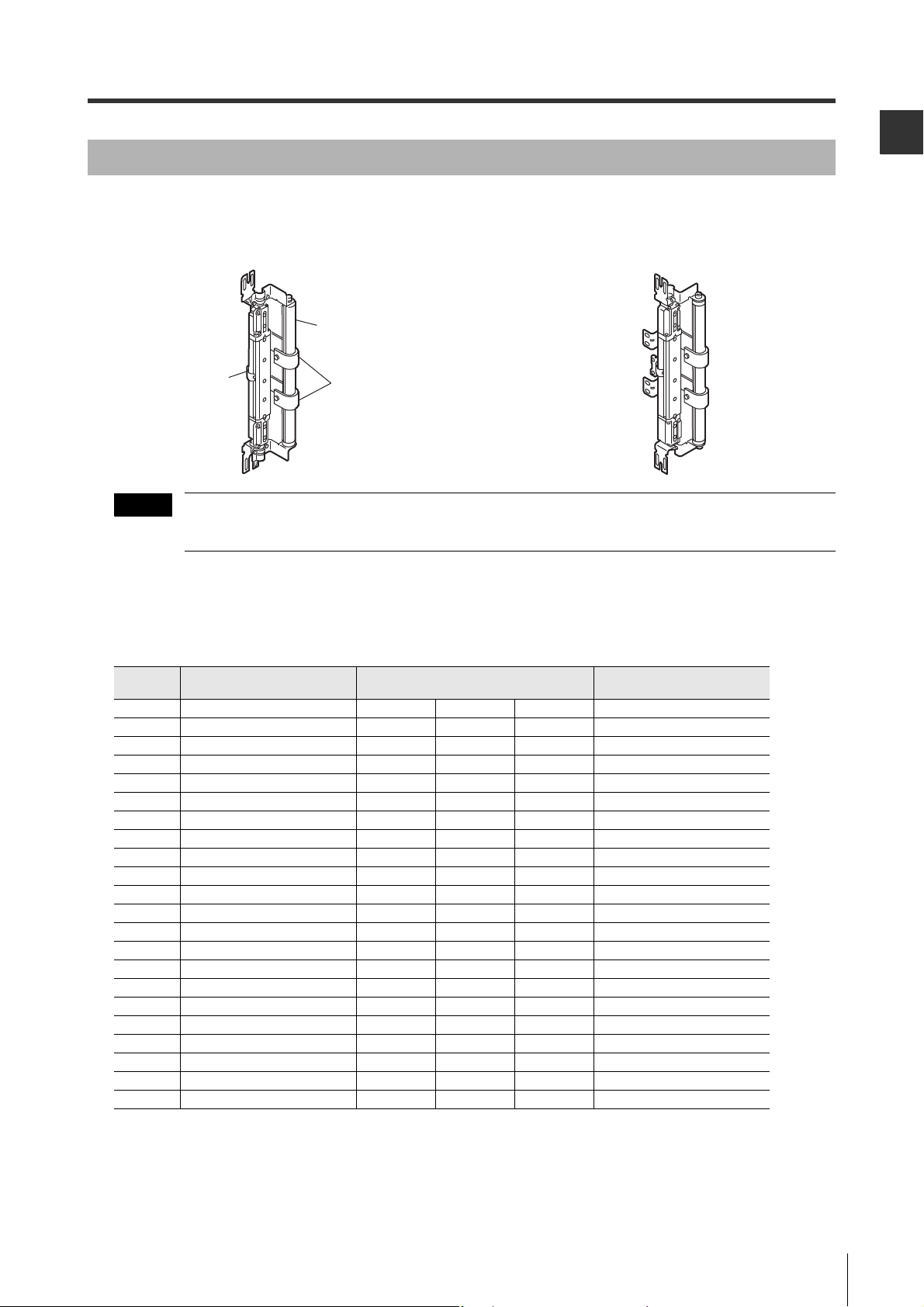
Standard mounting
bracket J (OP-83180)
Materials: SUS304
M3 (Length: 7 mm) screw x6
(For mounting to the unit)
x2
M3 (Length: 7 mm) screw x6
(For mounting to the unit)
Thin type mounting
bracket (OP-51698)
Materials: SUS304
x2
M3 miniature flathead (Length: 5 mm)
screw x6 (For mounting to the unit)
L-shaped mounting
bracket (OP-42371)
Materials: SUS304
x2
Standard mounting
bracket A (OP-42347)
Materials: SUS304
M3 (Length: 7 mm) screw x10
(For mounting to the unit)
M3 (Length: 7 mm) screw x10
(For mounting to the unit)
M3 (Length: 7 mm) screw x10
(For mounting to the unit)
x2
x2
x2
Standard mounting
bracket B (OP-42348)
Materials: SUS304
Standard mounting
bracket C (OP-42349)
Materials: SUS304
E-to-E mounting bracket (OP-42370)
Materials: SUS304
x2
Compact E-to-E mounting bracket (OP-83181)
Materials: SUS304
x2
NOTE
Space-saving bracket (OP-84260)
Material: SPHC
Standard mounting bracket (OP-84259)
Material: SPHC
Hexagon socket bolt
(M5, length: 6 mm, width
across flats: 3 mm) x 8
(For mounting to the unit)
x2
Hexagon socket bolt
(M5, length: 6 mm, width across
flats: 3 mm) x 4
Nut x 4
(For mounting to the unit)
x2
Mounting brackets (For SL-VF/VH/VL)
See "Assembling the Mounting Brackets (SL-VF/VH/VL)" (page 3-15).
Before Use
If the length for a single SL-V unit is 710 mm or greater, use a compact E-to-E mounting bracket or an Eto-E mounting bracket additionally as an intermediate support bracket.
For more information about the required number of intermediate support brackets and the limits on the
mounting position, see "Dimensions (SL-VF/VH/VL)" (page 7-9).
Mounting brackets (For SL-VFM/VHM/VLM)
See "Assembling the Mounting Brackets (SL-VFM/VHM/VLM)" (page 3-20).
SL-V-M-NO1-E
1-3
Page 16
1-2 Options
1
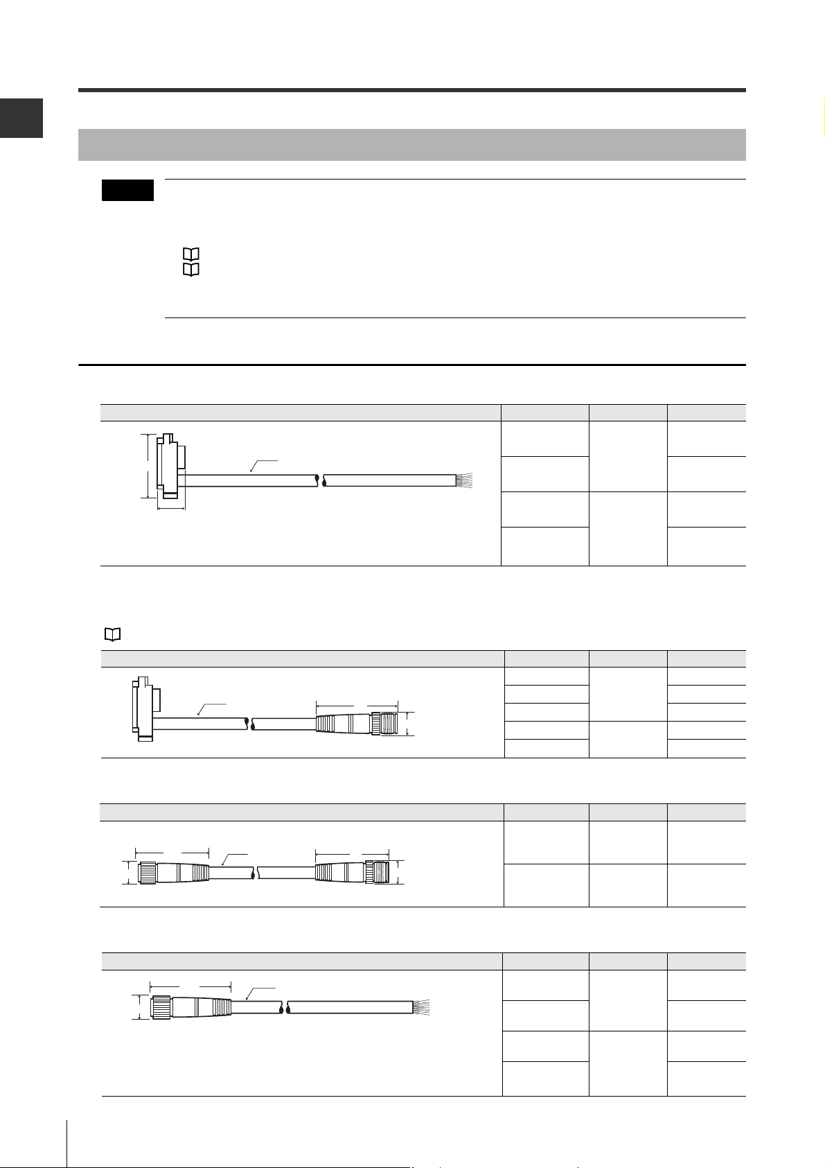
NOTE
8-wire shielded cable
Brown and blue: AWG24 (nominal cross-sectional area of 0.22 mm2)
Others: AWG26 (nominal cross-sectional area of 0.14 mm2)
(Transmitter/receiver set)
47
5.8
φ
14
φ
(Transmitter/receiver set)
M12 connector, male
41.5
14
5.8
φ
φ
47
14
φ
(Transmitter/receiver set)
M12 connector, male
M12 connector, female
41.5
14
φ
5.8
φ
(Transmitter/receiver set)
8-wire shielded cable
Brown and blue: AWG24 (nominal cross-sectional area of 0.22 mm2)
Others: AWG26 (nominal cross-sectional area of 0.14 mm2)
M12 connector, female
Before Use
Cables
• There are two types of cable: simple function type and multi-function type. The type of cable used determines the function that can be used. (The number of conductors is different from each other.) Therefore, the two types of cables cannot be mixed at the same time. Make sure to use the appropriate type
of cable for your applications.
See "Functions and Features" (page 2-1).
See "Cable Connections" (page 3-11).
• Cables with different output types cannot be combined. Be sure to match the PNP or NPN output type
especially when using the unit connection cable (for extension).
Simple function type
Unit connection cable
36.1
14.3
Shape Model Output type Length
SL-VP7P
φ
5.8
SL-VP15P
SL-VP7N
SL-VP15N
PNP
NPN
7 m
15 m
7 m
15 m
Unit connection cable (for extension use)
Used together with the junction cable or extension cable.
For more information about cable length standards, see "Cable length specification" (page 1-6).
Shape Model Output type Length
Junction cable
Shape Model Output type Length
Extension cable
Shape Model Output type Length
SL-VPC03P
SL-VPC5P 5 m
SL-VPC10P 10 m
SL-VPC03N
SL-VPC5N 5 m
SL-VCC10P PNP 10 m
SL-VCC10N NPN 10 m
SL-VC5P
SL-VC10P 10 m
PNP
NPN
PNP
0.3 m
0.3 m
5 m
1-4
SL-VC5N
NPN
SL-VC10N 10 m
5 m
SL-V-M-NO1-E
Page 17
1
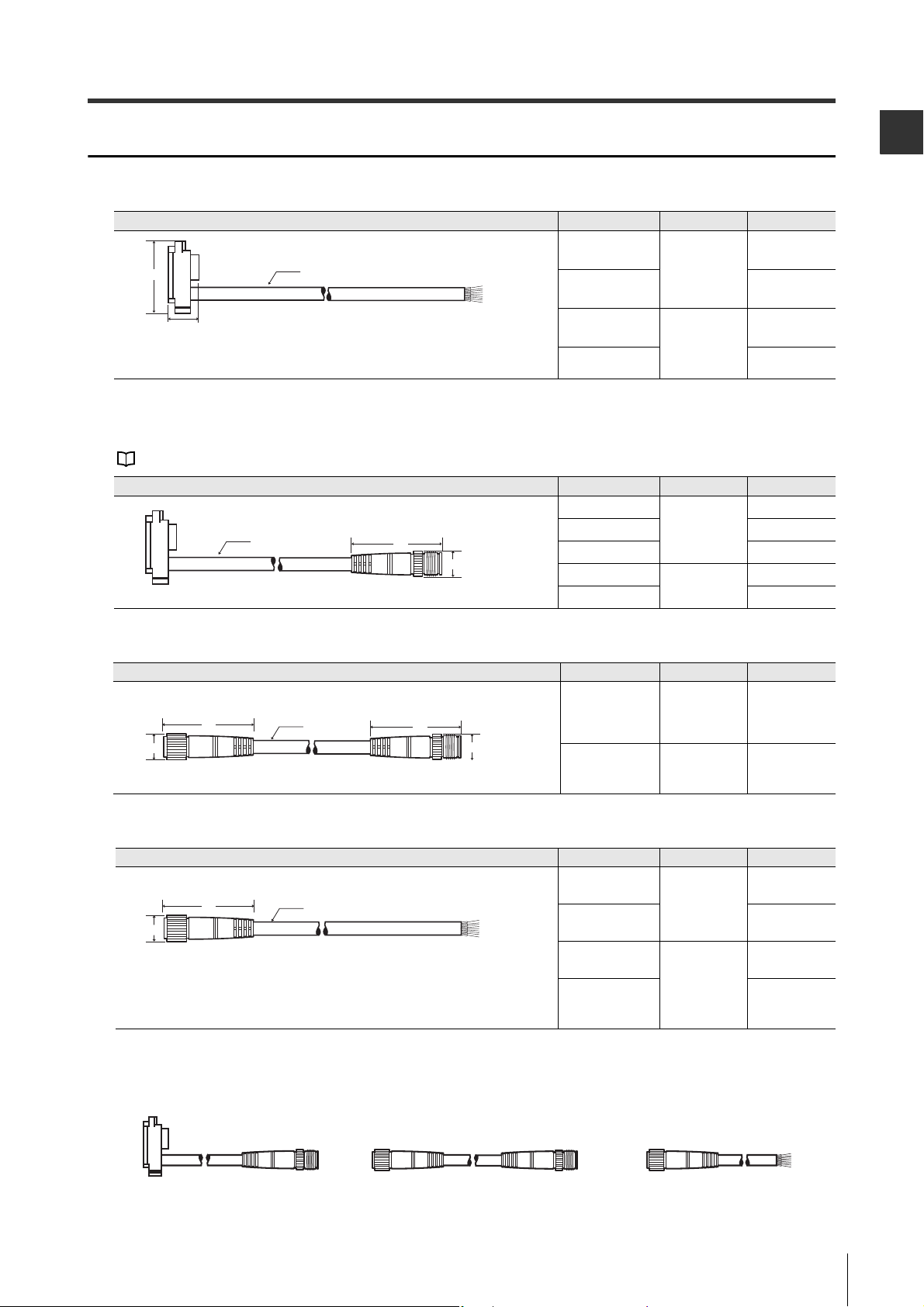
Multi-function type
12-wire shielded cable
Brown, blue: AWG24 (nominal cross-sectional area of 0.22 mm
2
)
Other: AWG26 (nominal cross-sectional area of 0.14 mm
2
)
(Transmitter/receiver set)
45
17
5.8
φ
φ
(Transmitter/receiver set)
M14 connector, male
(Transmitter/receiver set)
M14 connector, maleM14 connector, female
(Transmitter/receiver set)
M14 connector, female
12-wire shielded cable
Brown and blue: AWG24 (nominal cross-sectional area of 0.22 mm2)
Others: AWG26 (nominal cross-sectional area of 0.14 mm
2
)
Unit connection cable (for extension use)
Junction cable Extension cable
Male side Female side Male side Female side
Unit connection cable
1-2 Options
Before Use
Shape Model Output type Length
φ
36.1
14.3
5.8
Unit connection cable (for extension use)
Used with the junction cable or extension cable.
See "Cable length specification" (page 1-6).
Shape Model Output type Length
Junction cable
Shape Model Output type Length
SL-VP7PM
PNP
SL-VP15PM 15 m
SL-VP7NM
NPN
SL-VP15NM 15 m
SL-VPC03PM
SL-VPC5PM 5 m
SL-VPC10PM 10 m
SL-VPC03NM
SL-VPC5NM 5 m
PNP
NPN
7 m
7 m
0.3 m
0.3 m
φ
44
φ
17
5.8
Extension cable
Shape Model Output type Length
φ
44
φ
17
Cable combination example
5.8
45
φ
17
SL-VCC10PM PNP 10 m
SL-VCC10NM NPN 10 m
SL-VC5PM
PNP
SL-VC10PM 10 m
SL-VC5NM
NPN
SL-VC10NM 10 m
5 m
5 m
SL-V-M-NO1-E
1-5
Page 18
Before Use
1
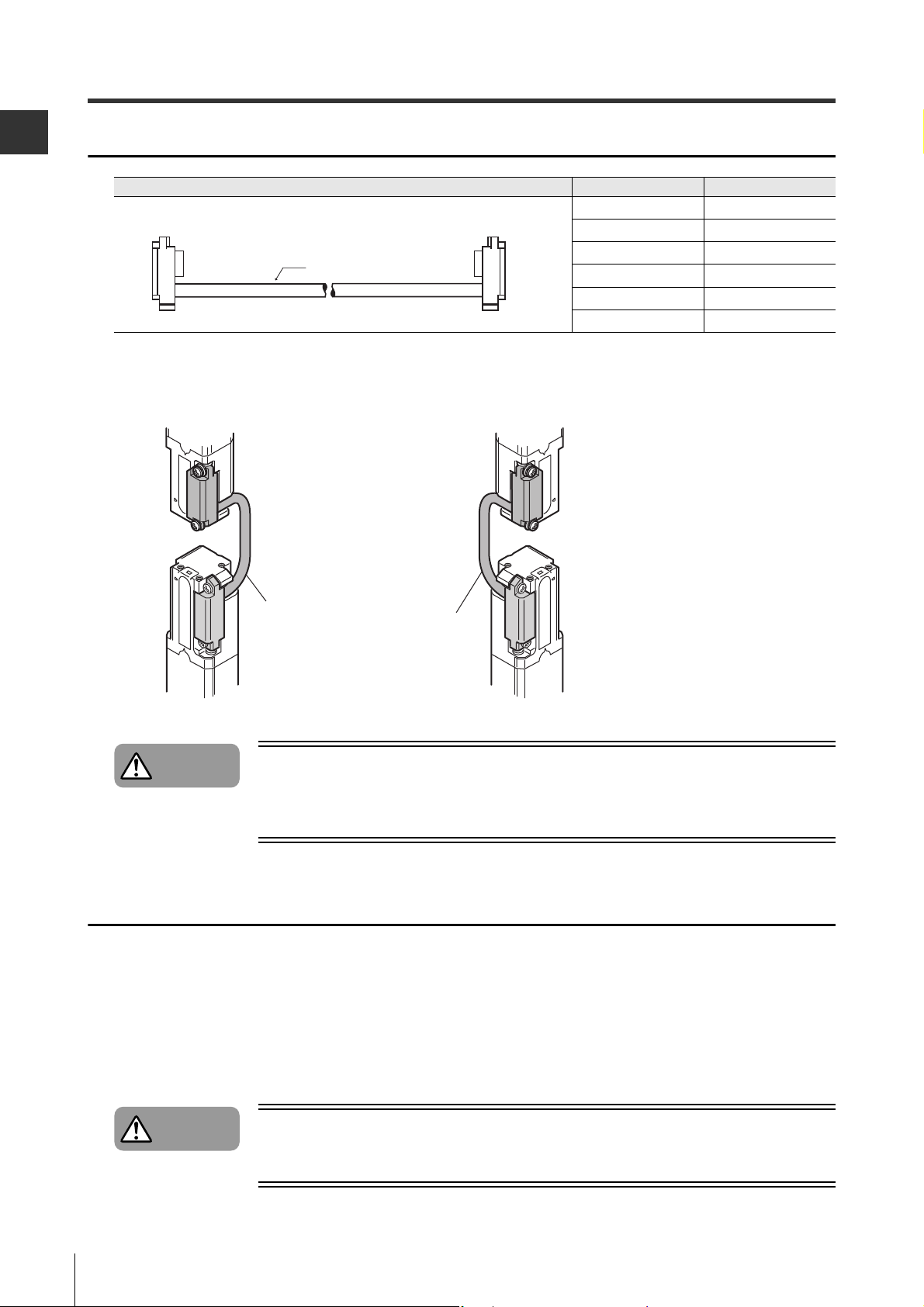
(Transmitter/receiver set)
5.8
φ
S
e
t
S
1
S
e
S
1
t
Transmitter Receiver
Danger
Danger
1-2 Options
Series connection cable
Shape Model Length
SL-VS0 0.08 m
SL-VS01 0.15 m
SL-VS05 0.5 m
SL-VS1 1 m
SL-VS3 3 m
SL-VS10 10 m
Figure of series connection
ub unit
Main uni
eries connection cabl
If a series connection cable has been cut or extended, it is not allowed to be used for the
SL-V. Use of a cut or extended cable may cause the safety function not to operate properly
and may cause a dangerous situation.
Cable length specification
eries connection cabl
ub unit
Main uni
1-6
When using the unit connection cable, junction cable and extension cable together, the sum of the length
for all the cables must be 30 m or less. This limitation is applicable to each unit, transmitter and receiver,
respectively. Since up to 3 of the SL-V units can be connected in series, up to 2 sets of series connection
cables are possible. Two sets of the SL-VS10 cables (cable length: 10 m) can be used. In this case, the
sum length of all types of cables, including the series connection cable, must be 50 m or less. This limitation is also applicable to each unit, transmitter and receiver, respectively.
Cables must be within the lengths specified. Failure to follow this specification may cause
improper operation of safety function, and may cause a dangerous situation.
SL-V-M-NO1-E
Page 19
1-2 Options
1
Protection bar
intermediate support bracket
(Material: SUS304)
Bar (Material: Aluminum)
Use a compact E-toE mounting bracket
(OP-83181) as the
intermediate support
mounting bracket for
the SL-V
Back mounting view when combined Side mounting view when combined
NOTE
Protection bar
This is an option that protects the detection surface of the SL-V against contacting workpieces. It can be
used with SL-VF/VH/VL.
The above figures show the state when standard mounting bracket A is combined. The unit can also be
combined with standard mounting bracket B, C, and J.
Protection bar
The model longer than the length of the SL-JB71 includes the required number of the intermediate support brackets.
Before Use
Model Name Applicable model
SL-JB15 Protection bar 150 mm (x1) - SL-V08H Sl-V04L 0
SL-JB23 Protection bar 230 mm (x1) SL-V23F SL-V12H SL-V06L 0
SL-JB31 Protection bar 310 mm (x1) SL-V31F SL-V16H SL-V08L 0
SL-JB39 Protection bar 390 mm (x1) SL-V39F SL-V20H SL-V10L 0
SL-JB47 Protection bar 470 mm (x1) SL-V47F SL-V24H SL-V12L 0
SL-JB55 Protection bar 550 mm (x1) SL-V55F SL-V28H SL-V14L 0
SL-JB63 Protection bar 630 mm (x1) SL-V63F SL-V32H SL-V16L 0
SL-JB71 Protection bar 710 mm (x1) SL-V71F SL-V36H SL-V18L 1
SL-JB79 Protection bar 790 mm (x1) SL-V79F SL-V40H SL-V20L 1
SL-JB87 Protection bar 870 mm (x1) SL-V87F SL-V44H SL-V22L 1
SL-JB95 Protection bar 950 mm (x1) SL-V95F SL-V48H SL-V24L 1
SL-JB103 Protection bar 1030 mm (x1) SL-V103F SL-V52H SL-V26L 1
SL-JB111 Protection bar 1110 mm (x1) SL-V111F SL-V56H SL-V28L 1
SL-JB119 Protection bar 1190 mm (x1) SL-V119F SL-V60H SL-V30L 1
SL-JB127 Protection bar 1270 mm (x1) SL-V127F SL-V64H SL-V32L 1
SL-JB143 Protection bar 1430 mm (x1) - SL-V72H SL-V36L 2
SL-JB159 Protection bar 1590 mm (x1) - SL-V80H SL-V40L 2
SL-JB175 Protection bar 1750 mm (x1) - SL-V88H SL-V44L 2
SL-JB191 Protection bar 1910 mm (x1) - SL-V96H SL-V48L 2
SL-JB207 Protection bar 2070 mm (x1) - SL-V104H SL-V52L 3
SL-JB223 Protection bar 2230 mm (x1) - SL-V112H SL-V56L 3
SL-JB239 Protection bar 2390 mm (x1) - SL-V120H SL-V60L 3
The required number of intermediate
support brackets for protection bar
Accessories:
Bar x1, bar bracket x2, hexagon socket bolt (width across flat: 5 mm, length: 15 mm) x2
The required number of the intermediate support bracket for the protection bar (2 types :for back mounting and side mounting)
SL-V-M-NO1-E
1-7
Page 20
1-2 Options
1
NOTE
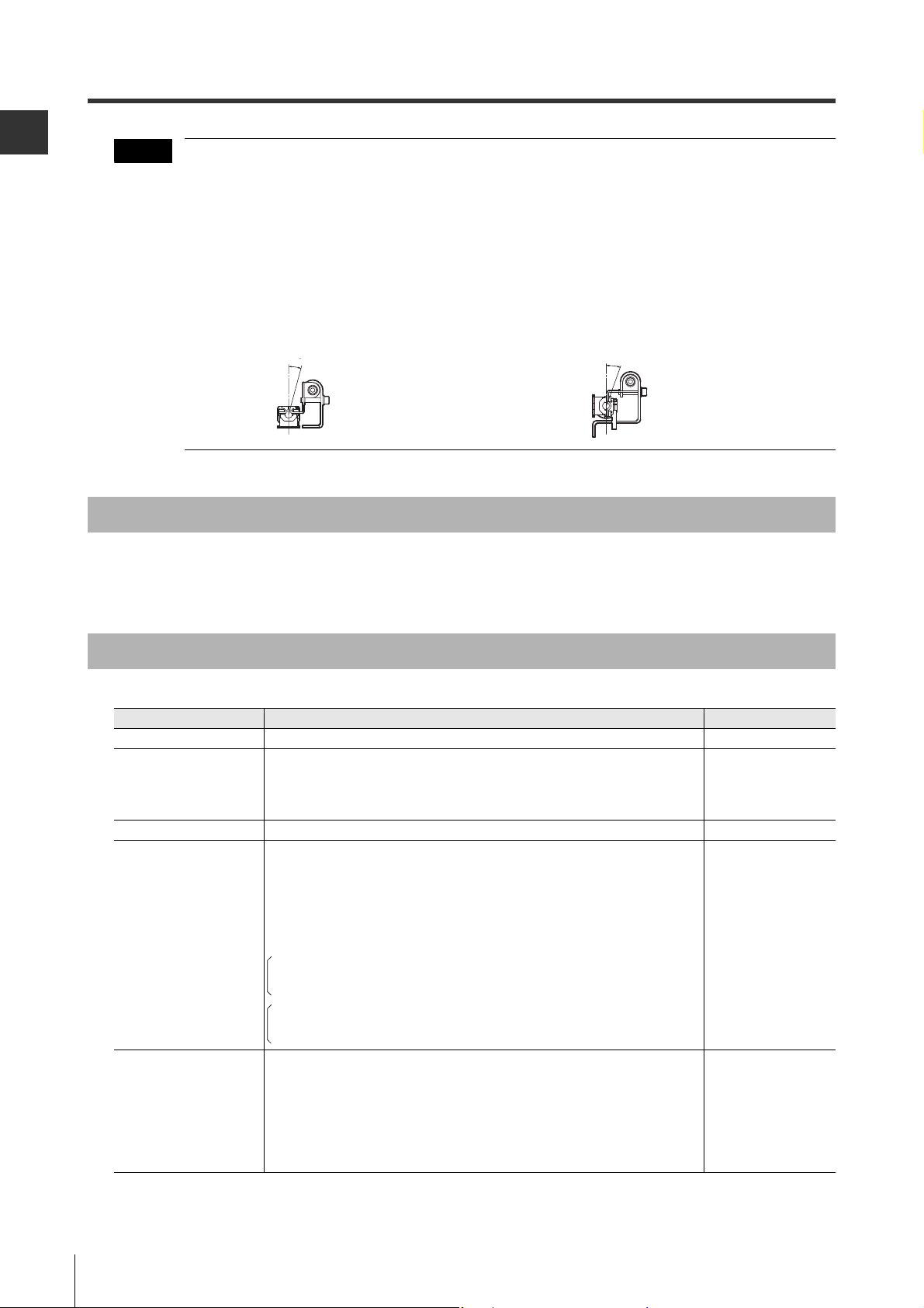
5
20˚
Before Use
• To mount the protection bar to the SL-V, standard mounting bracket A (OP-42347), B (OP-42348), C
(OP-42349), or J (OP-83180) is required.
• The bar and the standard mounting bracket are fixed with the hexagon socket bolts, so the angle of the
mounting bracket or the bar cannot be adjusted. However, the angle of the SL-V and the mounting
bracket can be adjusted for beam axis adjustment.
• The protection bar can be mounted to the back or side of the SL-V. Select an appropriate intermediate
support for the protection bar based on the mounting method.
• Install the unit at the angle shown in the following figure so that the protection bar or the intermediate
support bracket does not block the beam axes of the SL-V.
Back mounting Side mounting
1
Front protection cover and dimmer filter
KEYENCE can provide the front protection cover to protect the surface of the SL-V and also provide the
dimmer filter to shorten the operating distance.
Since these are optional, please contact your nearest KEYENCE office for further information.
SL-V Configurator (SL-VH1S)
When the SL-V Configurator is used, the following setting changes and functions are available.
Items Description Refer to page
Muting function
Muting bank function
Override function You can change the override condition. 2-45
Interlock function
Fixed blanking function
You can select the beam axes to be muted. The muting conditions can also be changed.
You can change the setting whether or not to use the Muting bank function.
When the muting bank function is used, the override function is disabled. Set
the interlock function with the SL-V Configurator because setting of the
interlock function with wiring is disabled.
The Interlock function enables OSSD to hold the OFF-state if no interruptions
are present in the detection zone upon startup (when the power turns on or the
lockout error condition is terminated by the reset input) or upon restart (when
the SL-V is interrupted and the OSSD becomes the OFF-state). This state is
called "interlock ". To recover from the interlock condition, the reset input must
be switched ON to OFF while no interruptions are present in the detection
zone. Automatic or manual can be selected individually for start and restart.
Automatic start mode : The OSSD automatically enters the ON-state when
Manual start mode : Enters interlock condition upon startup.
Automatic reset mode :
Manual reset mode : Enters interlock condition upon restart.
This function is enabled only for the specified beam axes. The OSSD can hold
the ON-state even when an interruption is present in the area. A desired area
can be set as an effective zone of this function on a pair of transmitter and the
receiver as well as on the all beam axes including the SL-V connected in
series. The area where this function is enabled can be set as desired not only
between a transmitter-receiver pair, but also on all the beam axes including the
SL-V connected in series.
no interruptions are present in the detection zone.
The OSSD automatically returns to the ON-state when
no interruptions are present in the detection zone.
2-29
2-32
2-7
2-48
1-8
SL-V-M-NO1-E
Page 21
1-2 Options
1
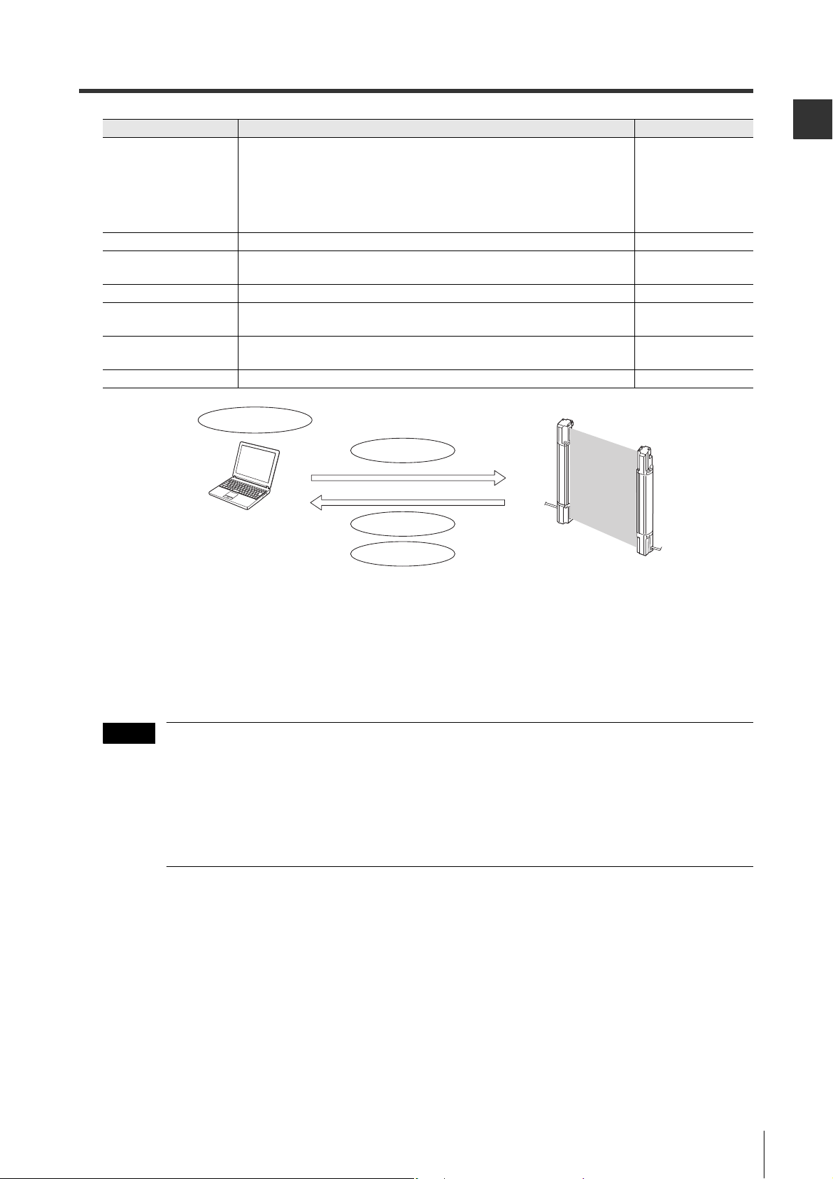
Upload configuration
Download configuration
Create/Save configuration
Monitor light intensity
Computer
SL-V Series Ver.3
Note
Items Description Refer to page
The OSSD holds the ON-state when the object is blocking only a specified
number of beam axes (one beam axis to the half of all axes can be set), and
Reduced resolution
function
Center indicator You can change the conditions for the center indicator to turn on, off, or blink. 6-6
EDM function
State information output
Emitting cycle change
Alert output monitoring
time change
Monitor function You can monitor the received light intensity of each beam axis on the SL-V. 2-50
the OSSD turns OFF only when the object is blocking more beam axes than
the specified number. This function is effective not only for a transmitter-
receiver pair, but also all the beam axes including the SL-V connected in
series.
You can change the setting whether or not to use the EDM function. The
tolerance time of the EDM input can also be changed.
You can change the output methods and the pulse time of the state information output.
You can change the laser emission cycle. The SL-V units with different laser
emission cycle can reduce the chance of mutual interference.
You can change for how many seconds the unstable clear state can continue
before issuing an alert output (alert output monitoring time).
2-49
2-15
2-18
3-8
2-26
Before Use
• You can create the configuration on the SL-V Configurator.
If you upload or download the configuration to or from the SL-V, you must connect the computer to the
SL-V.
• The SL-V that must be connected to the computer for configuration is only receiver on the main unit.
• The SL-V1UB, USB 1.1-compatible USB cable (supplied with the SL-V1UB) and the SL-V unit
connection cable are required for connection between the SL-V and the computer.
• The main unit must be a Ver.3 if you want to configure something through the SL-V Configurator.
In this case, the sub unit is not necessary to be Ver.3.
• The SL-VHS Series can not be used as the main unit.
• The OSSD goes to the OFF-state while the SL-V is connected to the SL-V1UB. You must
disconnect the SL-V1UB from the SL-V after uploading or downloading the configuration.
SL-V-M-NO1-E
1-9
Page 22
1
1-3 Part Description
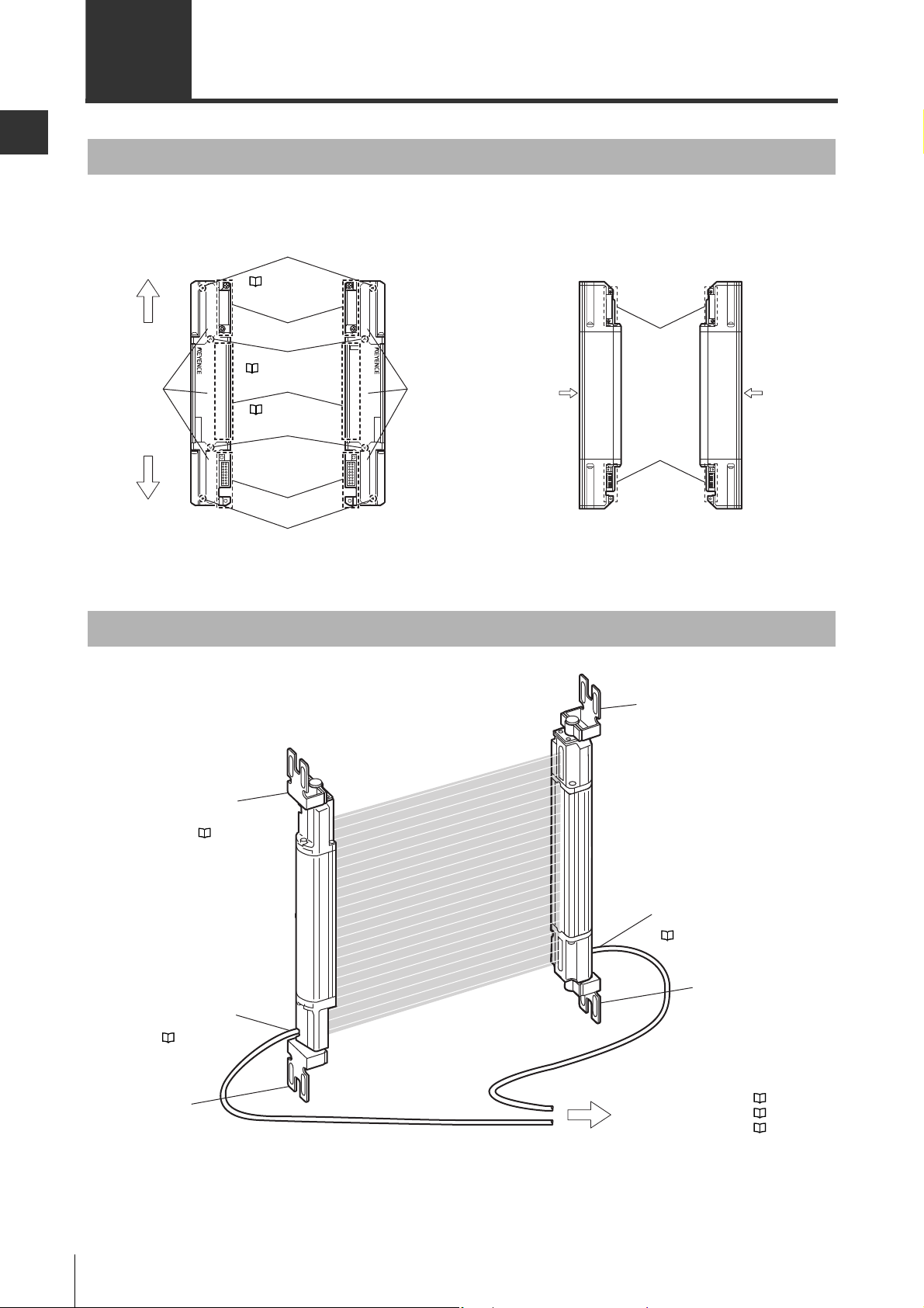
Transmitter Receiver
( page 1-11 details)
( page 3-4 details)
( page 6-1 details)
The connector and connector cover for the
SL-VFM/VHM/VLM are located on the back
side.
Mounting bracket
(option)
Mounting bracket
(option)
Unit connection cable
on the transmitter
(option)
Mounting bracket
(option)
Mounting bracket (option)
Unit connection cable
on the receiver (option)
Function of each I/O line
Power supply
External device connection
( page 3-15)
( page 3-11)
( page 2-3)
( page 4-1)
( page 3-11)
( page 4-2)
( page 3-11)
Before Use
SL-V main unit
Beam center-line mark
(upper)
1
*
To p
Connector cover
LEVEL
MUTE1
MUTE2
OSSD
INTER
LOCK
5
4
3
2
1
ø25 (0.98")SL-V08H
Detection
surface
Detection
surface
Detection
surface
Bottom
SL-V08H
ø25 (0.98")
LEVEL
5
4
3
2
1
WAIT
FUNCTION
OSSD
INTER
LOCK
Installation reference mark
Indicators
Installation reference mark
Connector receptacle
Beam center-line mark
(lower)
*1 The side where the connector cover has already been installed at shipment is the top side.
Transmitter Receiver
Connector cover
Connector
receptacle
Detection
surface
With options installed
1-10
SL-V-M-NO1-E
Page 23
1-3 Part Description
1
Protection
height
Specified detection capability
Protection zone
Operating distance
Detection zone
Detection
height
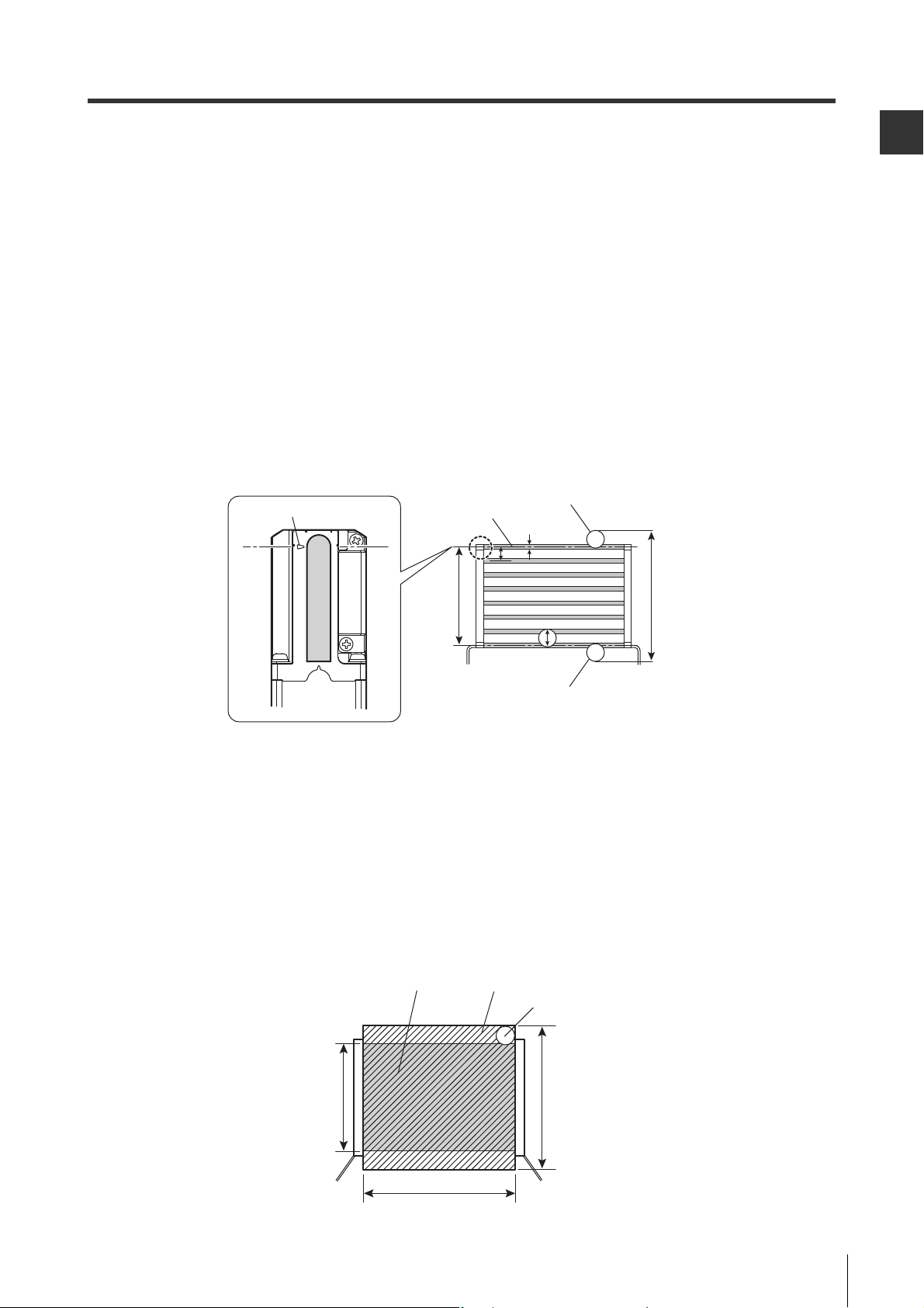
Beam center-line : An optical path joining the optical center of the emitting element on the transmitter to
the optical center of the corresponding receiving element on the receiver. the SL-V
must be installed so that the beam center-line mark on the transmitter and that on the
receiver face one another and are located at the same height.
Detection height : The height from the top beam center-line to the bottom beam center-line (length).
Protection height : An object approaching the detection zone from the top of the detection height is first
detected at point A, which is the distance of the detection capability from the top of
the detection height. The equivalent position on the bottom is called point B. The
height from the top edge of the specified detection capability that exists at point A to
the bottom edge of the specified detection capability that exists at point B is called a
"protection height".
The following calculation formula can be defined:
Protection height = "Detection height" + 2 x "the specified detection capability"–"beam
axis diameter".
* Refer to the following diagram for an explanation of beam center-line, detection height and protection height.
Before Use
Beam center-line mark
Beam center-line
height
a: Beam axis spacing
b: Beam axis diameter
c: Detection capability
Specified detection capability (position A)
b
a
Protection heightDetection
c
Specified detection capability (position B)
Detection zone: The zone in which the specified detection capability can be detected. The detection zone
of the SL-V indicates a square area formed with the detection height and the operating
distance. When a part or whole of the specified detection capability is present in this area,
the light of the SL-V is blocked, and then the OSSD goes to OFF state.
Protection zone: The square area formed with the protection height and the operating distance, which
is broader than the detection zone. When a whole of the specified detection capability is present in this area, the light of the SL-V is blocked, and then the OSSD goes to
OFF state.
* Refer to the following diagram for detection zone and protection zone.
SL-V-M-NO1-E
1-11
Page 24

Before Use
1
1-3 Part Description
MEMO
1-12
SL-V-M-NO1-E
Page 25

2
Functions and Features
2-1 Cable Selection and Function . . . . . . . . . . . . . . . . . . . . . . . . . 2-2
2-2 Self-diagnosis Function . . . . . . . . . . . . . . . . . . . . . . . . . . . . . . 2-4
2-3 Series Connection . . . . . . . . . . . . . . . . . . . . . . . . . . . . . . . . . . 2-6
2-4 Interlock Function . . . . . . . . . . . . . . . . . . . . . . . . . . . . . . . . . . 2-7
2-5 AUX (Auxiliary) Output. . . . . . . . . . . . . . . . . . . . . . . . . . . . . . 2-14
2-6 External Device Monitoring (EDM Function) . . . . . . . . . . . . . 2-15
2-7 Wait Input Function . . . . . . . . . . . . . . . . . . . . . . . . . . . . . . . . 2-16
2-8 State Information Output . . . . . . . . . . . . . . . . . . . . . . . . . . . . 2-18
2-9 Alert Output . . . . . . . . . . . . . . . . . . . . . . . . . . . . . . . . . . . . . . 2-25
2-10 Clear/Blocked Output. . . . . . . . . . . . . . . . . . . . . . . . . . . . . . . 2-27
2-11 Temporary Suspension of Safety Function . . . . . . . . . . . . . . 2-29
2-12 Fixed Blanking . . . . . . . . . . . . . . . . . . . . . . . . . . . . . . . . . . . . 2-48
2-13 Reduced Resolution . . . . . . . . . . . . . . . . . . . . . . . . . . . . . . . 2-49
2-14 I/O Monitoring Function . . . . . . . . . . . . . . . . . . . . . . . . . . . . . 2-50
SL-V-M-NO2-E
2-1
Page 26

2
2-1 Cable Selection and Function
Functions
Functions and Features
There are two types of cables that can be used with the SL-V. One is simple function type and another is
multi-function type. The type of cable used determines the functions that can be used. (The number of
wires is different from each other.) Additionally, there are functions that can be activated with or without
the SL-V Configurator (SL-VH1S). Refer to the following chart.
Usable functions
Function and overview
[Self-diagnosis]
Detects a failure to the SL-V.
[Series connection]
Expands the protection zone with the SL-V
connected in series.
[Interlock]
The SL-V prevents the OSSD from automatically
going to the ON-state.
[EDM]
Detects a failure on external devices.
[Wait input]
Puts the OSSD into an OFF-state through a signal
from an external device.
[AUX (auxiliary) output]
Output for OSSD monitors.
[State Information output]
Informs the external devices of the current state of
the SL-V.
[Alert output]
Informs the external devices when the amount of
receiving light is decreased.
[Clear/Blocked output]
Informs to the external devices whether beam axis is
clear or blocked.
[Muting/Override]
Temporary suspension of safety function.
[Fixed blanking]
Keeps the OSSD ON-state even when an obstacle is
in a protection zone.
[Reduced resolution]
Keeps the OSSD ON-state even if the moving
obstacle is in the protection zone.
[I/O monitoring function]
Informs the user of the state of several I/Os on the
SL-V through the indicators of the SL-V.
[Emitting cycle change]
Reduces the possibility of light interference.
[Center Indicator]
Lights to indicate the condition of the SL-V.
Simple function
type cable
XX 2-4
XX 2-6
(X) (X) 2-7
X X 2-15
X X 2-16
X X 2-14
- X 2-18
- X 2-25
- X 2-27
- (X) 2-29
S S 2-48
S S 2-49
X X 2-50
SS 3-8
(X) (X) 6-6
Multi-function type
cable
Page
2-2
X : This function can be used without the SL-V Configurator
(X) : Parts of this function can be used without the SL-V Configurator
S : The SL-V Configurator is required
- : This function is not available.
SL-V-M-NO2-E
Page 27
2
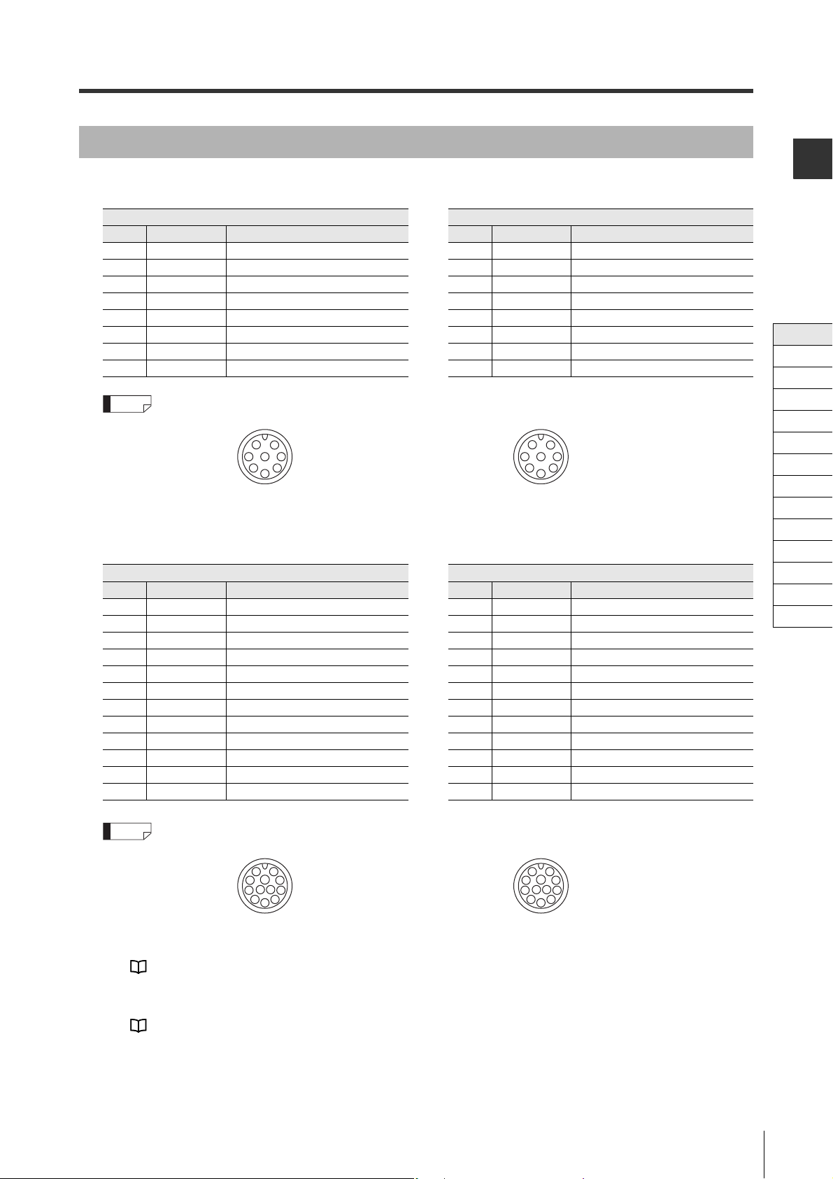
Cable color and pin assignment
Reference
Reference
6
10
12
11
3
4
5
21
9
8
7
6
10
11
12
9
8
7
12
3
4
5
2-1 Cable Selection and Function
Simple function type
Transmitter Receiver
Pin No.
Wire color Assigned function
Pin No.
Wire color Assigned function
1 Pink Interlock mode selection input 1 White OSSD 2
2 Brown +24 V 2 Brown +24 V
3 Violet Wait input 3 Black OSSD 1
4 Green Interlock-reset-ready output 4 Yellow RESET input
5 Orange Communication cable 1 (RS485_+) 5 Orange Communication cable 1 (RS485_+)
6 Orange/Black Communication cable 2 (RS485_-) 6 Orange/Black Communication cable 2 (RS485_-)
7Blue0 V 7Blue0 V
8 Red AUX (auxiliary) output 8 Red EDM input
M12 connector male pin assignment M12 connector female pin assignment
2
1
83 7
4
6
5
1
2
87 3
6
4
5
Multi-function type
Transmitter Receiver
Pin No.
10 Grey/Black State information output 2 10 Yellow/Black Muting lamp output
11 Pink/Black Alert output 11 Light blue Muting input 1
12 White/Black Clear/Blocked Output 12
Wire color Assigned function
1 Pink Interlock mode selection input*
1
Pin No.
Wire color Assigned function
1 White OSSD 2
2 Brown +24 V 2 Brown +24 V
3 Violet Wait input*
1*2
3 Black OSSD 1
4 Green Interlock-reset-ready output 4 Yellow RESET input
5 Orange Communication cable 1 (RS485_+) 5 Orange Communication cable 1 (RS485_+)
6 Orange/Black Communication cable 2 (RS485_-) 6 Orange/Black Communication cable 2 (RS485_-)
7Blue0 V 7Blue0 V
8 Red AUX (auxiliary) output 8 Red EDM input
9 Grey State information output 1 9 Red/Black Override input*
Light blue/Black
Muting input 2
Functions and Features
Cable
Self-diagnosis
Series Connection
Interlock
AUX
EDM
Wait
State Information
Alert
Clear/Blocked
Suspension
Fixed
Reduced
Monitoring
1*2
M14 connector male pin assignment M14 connector female pin assignment
*1 The following changes apply when the muting bank function is enabled.
Pink: Muting bank input 3, Violet: Muting bank input 1, Red/black: Muting bank input 2
"Muting function" (page 2-29)
*2 If the center indicator is set to the Built-in indicator mode, this is used for the control input of the indi-
cation state.
"Center Indicator" (page 6-6)
SL-V-M-NO2-E
2-3
Page 28

Functions and Features
2
2-2 Self-diagnosis Function
Lockout condition
The SL-V performs self-diagnosis for approx. 4.5 seconds after the power is turned on and checks for
errors in the SL-V. Self-diagnosis is also performed periodically during normal operations.
If the self-diagnosis function detects an error, the SL-V goes to Lockout condition and the OSSD is kept in
OFF state even if no interruption exists in the detection zone. The indicators operate in the following manner during lockout condition.
Bar LED : Indication corresponding to the cause of the error
See "Troubleshooting" (page A-2)
Function indicator : Interlock indicator is blinking in yellow.
See "Function Indicators" (page 6-5)
Center indicators : All indicators are blinking in red.
See "Center Indicator" (page 6-6)
To release the lockout condition, first remove the cause of the error, and then either activate reset input or
turn the power off and on again.
See "Time chart for the termination of lockout condition due to reset input" (page 2-13)
Self-diagnosis description
Transmitter
• Error in external power supply voltage
• Failure in internal power supply circuit
• Failure in light emitting element and light receiving circuit
• CPU overdrive
• Memory error
• Cable open/short-circuit
Receiver
• Error in external power supply voltage
• Failure in internal power supply circuit
• Failure in light receiving element and detection circuit
• CPU overdrive
• Memory error
• Failure in safety output circuit (OSSD)
• Cable open/short-circuit
• Program monitoring
2-4
SL-V-M-NO2-E
Page 29
2
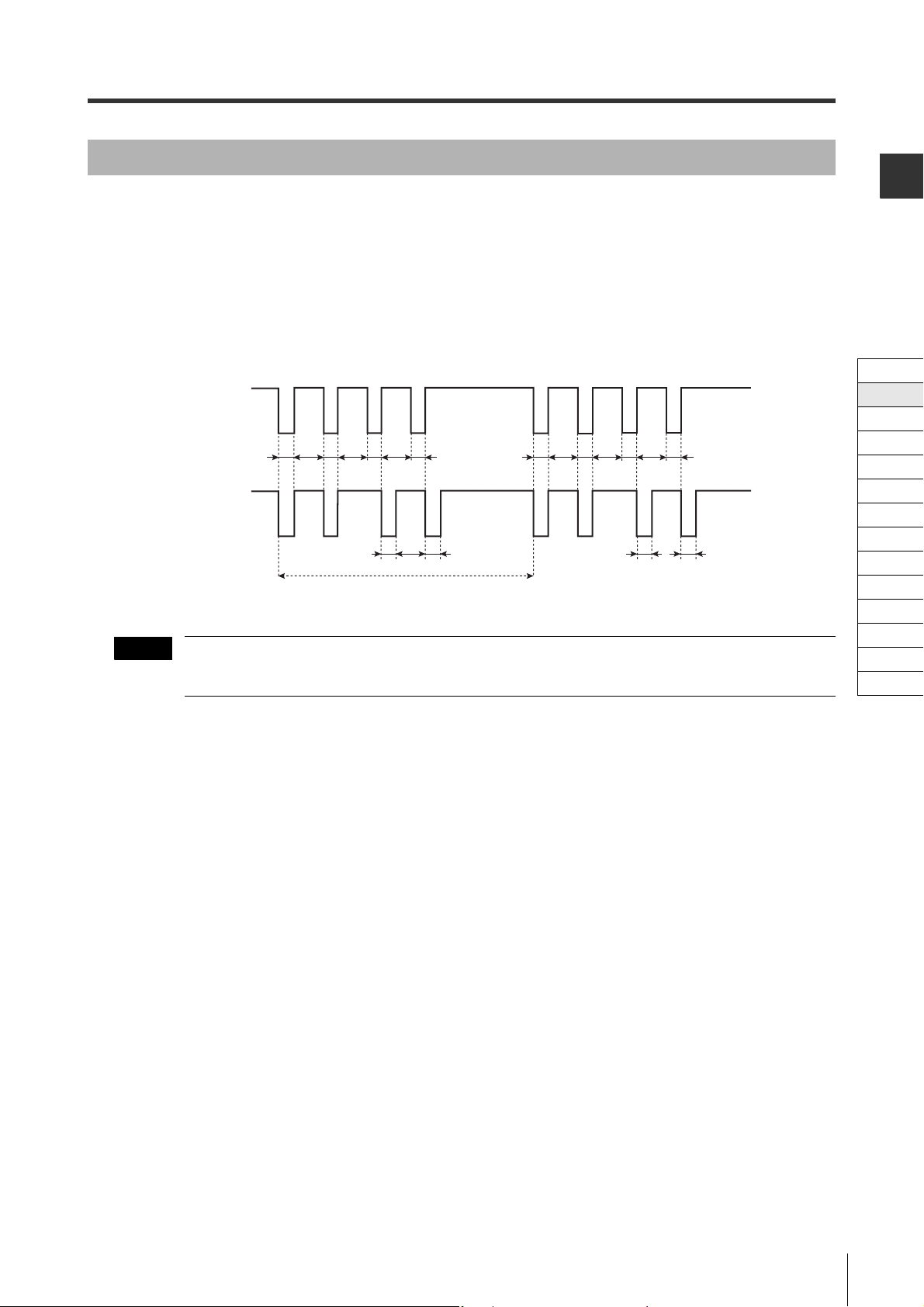
OSSD
NOTE
2-2 Self-diagnosis Function
The OSSD is a safety-related control output. It connects to an external device (load), such as an FSD or
MPCE. The SL-V generates self-diagnosis signals on its internal control circuit to perform diagnostics on
the output circuit (OSSD). These signals periodically force the OSSD into a temporary OFF state when no
interruption exists in the detection zone.
The internal control circuit receives a feed-back signal (OFF signal) based on the self-diagnosis, the SLV determines that its output circuit is operating normally. If this OFF signal is not returned to the internal
control circuit, the SL-V determines that there is a problem in its output circuit or wiring and goes to the
lockout condition.
ON
OSSD1
OFF
BB
AA AA
OSSD2
ON
OFF
BB
AAAA
Approx. 100 ms
A : 60 μs max.
B : Approx. 10 ms
B
AAAA
The devices connected to the OSSD, such as safety relay or contactor, should not respond to these temporary, self-diagnostic OFF-signals.
B
Functions and Features
Cable
Self-diagnosis
Series Connection
Interlock
AUX
EDM
Wait
State Information
Alert
Clear/Blocked
Suspension
Fixed
Reduced
Monitoring
SL-V-M-NO2-E
2-5
Page 30
Functions and Features
2
Transmitter
Receiver
Transmitter
Receiver
Transmitter
Receiver
Unit connection cable
Series connection
cable
(10 m max.)
Series connection
cable
(10 m max.)
Sub unit 1
Main unit
Sub unit 2
Reference
NOTE
2-3 Series Connection
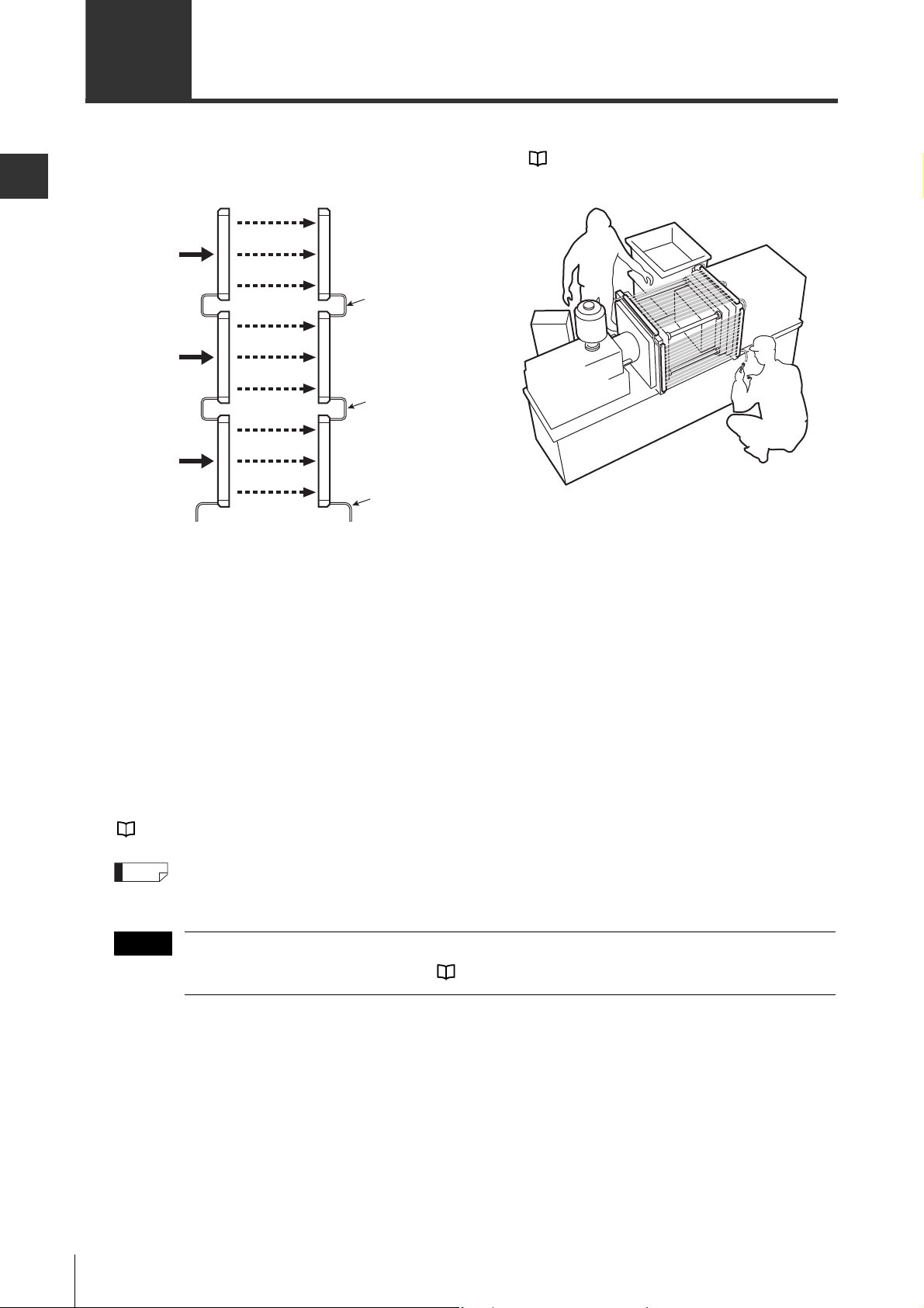
Up to three SL-V units can be serially connected and used as a single light curtain. Use the series connection cables that KEYENCE provides as an optional part. ( See "Series connection cable" (page 1-6))
Example of use with 3 units in series connection
Benefits
• Prevents the light interference between the connected SL-Vs
• Simplified wiring because the wiring for OSSD or synchronization cable
• Combining the SL-VF (M), SL-VH (M) and the SL-VL (M) is allowable in series connections even though
they have different respective detection capabilities.
Limitations
• Up to 3 units
• Up to 240 total number of beam axes
• The length of one series connection cable must be 10 m or less. When connecting three units in series,
the total length of two cables must be 20 m or less.
See "Cable Connections" (page 3-11).
Even when series connection cannot be established, light interference is reduced by the light
interference prevention function. No special settings are required.
Series connection is required for secure light interference prevention. When not connecting the SL-V units
in series, install the units by referring to "Light Interference Prevention Method" (page 3-8)
2-6
SL-V-M-NO2-E
Page 31

2
2-4 Interlock Function
Interlock is a function to prevent that the OSSD automatically goes to the ON-state from the OFF-state.
You can prevent the unintended start-up and/or the unintended restart of the machine if the interlock is
applied to the SL-V.
You can determine whether the interlock function is enabled at start-up, at restart or both through the
SL-V Configurator (SL-VH1S).
In this sentence, start-up and restart means as follows.
Start-up:
1) When the power is supplied
2) When the SL-V is restored from lockout condition thorough reset input
Functions and Features
Restart:
1) When the OSSD goes back to the ON-state from OFF-state, except for the start-up
On the other hand, you can also determine whether the interlock function is enabled at start-up and at
restart through the wiring method.
The setting of combination for start and restart interlock is as follows.
(X: available -: not available)
Interlock Setting method
Start
Interlock
Automatic Automatic X X
Manual Automatic - X
Automatic Manual - X
Manual Manual X X
Restart
Interlock
SL-V wiring SL-VH1S
Start mode
Automatic start mode: Interlock function does not work. The SL-V starts operation automatically without
the reset operation.
The OSSD goes to the ON-state automatically if the SL-V detects no interruption in the detection zone at
start-up.
This mode can be used for the machine that nobody can go into or approach the hazardous area with
only passing through the protection zone, or can be used if the safety-related part of a control system
other than the SL-V, such as safety relay unit, can ensure the safety with other means.
Cable
Self-diagnosis
Series Connection
Interlock
AUX
EDM
Wait
State Information
Alert
Clear/Blocked
Suspension
Fixed
Reduced
Monitoring
Manual start mode: Interlock function works. The SL-V starts operation if the SL-V receives the reset
operation.
The OSSD keeps the OFF-state at start-up (Interlock condition). It is necessary to perform the reset operation when the SL-V detects no interruption in the detection zone, in order that the machine starts operation. Because of reset operation, the OSSD goes to the ON-state, and then interlock condition is
terminated.
Unexpected/Unintended start-up of the machine or machinery can be prevented.
Restart mode
Automatic reset mode: Interlock function does not work. The SL-V starts operation automatically without
the reset operation.
The OSSD goes to the ON-state automatically at restart if the object detected by the SL-V is removed
from the detection zone.
SL-V-M-NO2-E
2-7
Page 32

Functions and Features
2
0V
+24V
0V
+24V
Transmitter
Main
circuit
Receiver
Main
circuit
Blue
Brown
Yellow (reset input)
Blue
Brown
Pink (interlock mode selection input)
When using a PNP output type cable When using an NPN output type cable
NOTE
2-4 Interlock Function
This mode can be used for the machine that nobody can go into or approach the hazardous area with
only passing through the protection zone, or can be used if the safety-related part of a control system
other than the SL-V, such as safety relay unit, can ensure the safety with other means.
Manual reset mode: Interlock function works. The SL-V starts operation if the SL-V receives the reset
operation.
The OSSD keeps the OFF-state even if the object detected by the SL-V is removed from the detection
zone. (Interlock condition).
It is necessary to perform the reset operation when the SL-V detects no interruption in the detection
zone, in order that the machine starts operation. Because of reset operation, the OSSD goes to the ONstate, and then interlock condition is terminated.
Automatic start / Automatic reset mode
This section explains the settings for the combination of automatic start and automatic reset mode.
Configuration
Wiring method (Pink wire on the transmitter)
SL-V can be set as the combination of automatic start and automatic reset mode through the wiring in
the following manner. If this function is set through the SL-VH1S, it cannot be set through the wiring.
Software method (SL-VH1S)
Refer to the "SL-VH1S User’s Manual".
Wiring
Transmitter
Main
circuit
Receiver
Main
circuit
• If the power is turned on with an open circuit on the pink wire (interlock mode selection input), the SL-V
goes into the I/O monitoring mode.
See "I/O Monitoring Function" (page 2-50).
• If the power is turned on with an open circuit on the yellow wire (reset input) and the type of cable is
incorrect, the SL-V goes to the lockout condition because of "interlock error".
See "Troubleshooting" (page A-2).
• When the interlock is configured through the SL-VH1S, the pink wire on the transmitter must be insulated from the external (keep open-circuit) because it is not needed if it is not used for other functions.
Brown
Pink (interlock mode selection input)
Blue
Brown
Yellow (reset input)
Blue
+24V
0V
+24V
0V
2-8
SL-V-M-NO2-E
Page 33

2
Releasing lockout condition with a switch
When using a PNP output type cable When using an NPN output type cable
Clear
(Not interrupted)
Blocked
(Interrupted)
SL-V
Reset input
Lockout condition
Approximately 4.5 seconds
0.1 to 1 second
*1
ON
OFF
ON
OFF
OSSD
Use the reset input (yellow wire on the receiver) for releasing lockout condition.
See "Lockout condition" (page 2-4)
See "Time chart for the termination of lockout condition due to reset input" (page 2-13)
2-4 Interlock Function
Functions and Features
+24V
0V
+24V
Short-circuit current 2.5 mA
0V
Transmitter
Main
circuit
Receiver
Main
circuit
+24V
Pink (interlock mode selection input)
Blue
Brown
Yellow (reset input)
Blue
0V
+24V
Short-circuit current 2.5 mA
0V
Transmitter
Main
circuit
Receiver
Main
circuit
Pink (interlock mode selection input)
Blue
Yellow (reset input)
Blue
When using a switch to release the lockout condition, use a switch rated at 24 V DC, 2 to 3 mA.
Time chart
Cable
Self-diagnosis
Series Connection
Interlock
AUX
EDM
Wait
State Information
Alert
Clear/Blocked
Suspension
Fixed
Reduced
Monitoring
*1 If the lockout condition is released while reset input is OFF, an interlock error occurs and the SL-V
returns to the lockout condition. Reset input must go back to ON state within one second.
"Troubleshooting" Page A-2
SL-V-M-NO2-E
2-9
Page 34

2-4 Interlock Function
2
Blue
0V
Pink (interlock mode selection input)
+24V
Blue
Brown
Brown
0V
Yellow (reset input)
+24V
Short-circuit current 2.5 mA
Transmitter
Main
circuit
Receiver
Main
circuit
Transmitter
Main
circuit
Receiver
Main
circuit
Blue
Pink (interlock mode selection input)
+24V
Blue
Brown
Brown
Yellow (reset input)
Short-circuit current 2.5 mA
When using a PNP output type cable When using an NPN output type cable
NOTE
Danger
Other than Automatic start / Automatic reset mode
Functions and Features
This section explains the settings other than the combination of automatic start and automatic reset mode.
Configuration
Wiring method (Pink wire on the transmitter)
SL-V can be set as the combination of manual start and manual reset mode through the wiring in the
following manner. If this function is set through the SL-VH1S, it cannot be set through the wiring.
Software method (SL-VH1S)
Refer to the "SL-VH1S User’s Manual".
Wiring
• When using a switch for reset input, use a switch rated at 24 V DC, 2 to 3 mA.
• If the power is turned on with an open circuit on the pink wire (interlock mode selection input), the SL-V
enters the I/O monitoring state.
See "I/O Monitoring Function" (page 2-50).
• If the power is turned on while the yellow wire (reset input) is turned on and the type of cable is incorrect, the SL-V goes to the lockout condition because of “interlock error”.
See "Troubleshooting" (page A-2).
• When the interlock is configured through the SL-VH1S, the pink wire on the transmitter must be insulated from the external (keep open-circuit) because it is not needed if it is not used for other functions.
2-10
• The interlock reset mechanisms (such as switches) must be installed so that the whole haz-
ardous zone can be checked by the responsible personnel and that operations of the interlock reset mechanisms are not possible within the hazardous zone.
• Be sure to confirm absolutely that there is nobody in the hazardous zone, before the inter-
lock is released by the interlock reset mechanism. Failure to follow this warning may result
in significant harm to the machine operators including injury or death.
SL-V-M-NO2-E
Page 35

2-4 Interlock Function
2
Danger
Interlock-reset-ready output
0V
+24V
Receiver
Main
circuit
Input device
Green
Blue
Brown
For connecting a PNP input device
Interlock-reset-ready output
0V
+24V
Transmitter
Main
circuit
Input device
Green
Blue
Brown
For connecting an NPN input device
NOTE
Interlock-reset-ready output
The Interlock-reset-ready output is a NON-SAFETY-RELATED function.
The Interlock-reset-ready output (Green wire on the transmitter) is enable when manual start or manual
restart is set. This output informs the external devices (non-safety-related devices) that the interlock state
on the SL-V is ready to be released by pressing the reset button because the SL-V does not detect any
interruptions in the detection zone.
• This output is not a safety-related output but just information for usability. Activation of this
output never guarantees the safety of whole machine system and never configures a part of
the interlock reset mechanism. The safety of whole machine system must be established by
the safety-related control system, and the entire responsibility for that establishment and
also the use of this function must be on the customer. Failure to follow this warning may
result in significant harm to the machine operators including injury or death.
Refer to page 2-10 for more information on the warning and description about resetting
interlock.
• Be sure to confirm absolutely that there is nobody in the hazardous zone, before the inter-
lock is released by the interlock reset mechanism. Failure to follow this warning may result
in significant harm to the machine operators including injury or death.
• The Interlock-reset-ready output is not allowed to be used as the safety output for safety-
related control system. Usage of this function as safety output may result in significant harm
to the machine operators including serious injury or death.
Wiring
Functions and Features
Cable
Self-diagnosis
Series Connection
Interlock
AUX
EDM
Wait
State Information
Alert
Clear/Blocked
Suspension
Fixed
Reduced
Monitoring
Output rating: 26.4 V DC or less, 50 mA or less
Regardless of whether PNP or NPN output type cables are selected, the SL-V Interlock-reset-ready output can be connected to either PNP input devices or NPN input devices. Refer to the time charts mentioned in this manual because the output logic of the Interlock-reset-ready output is different depending on
the connected device.
SL-V-M-NO2-E
2-11
Page 36

Functions and Features
2
No
interruption
Interruption
ON
SL-V
(1)
(2)
Reset input
Interlock-reset-ready
output
Interlock
T1
150 ms max.
100 ms max.
100 ms min.
OFF
ON
OFF
ON
OFF
ON
OFF
OSSD
NOTE
SL-V
No
interruption
Interruption
ON
(1)
Wait input
(2)
Reset input
Interlock-reset-ready
output
Interlock
150 ms max.100 ms max.
200 ms max.
100 ms min.
OFF
ON
OFF
ON
OFF
ON
OFF
ON
OFF
OSSD
NOTE
2-4 Interlock Function
Time chart
Time chart in case of interruption in the detection zone.
(1) When using a PNP output type cable to connect to a PNP input device, or when using an NPN out-
put type cable to connect to an NPN input device
(2) When using a PNP output type cable to connect to an NPN input device, or when using an NPN out-
put type cable to connect to a PNP input device
T1 : Response time (OSSD) ( page 7-7)
The interlock can be terminated due to the reset input if the SL-V detects no interruption in the detection
zone. This operation does not relate to the condition of the Interlock-reset-ready output state because this
output is a non-safety output.
Time chart when using wait input
See "Wait Input Function" (page 2-16)
(1) When using a PNP output type cable to connect to a PNP input device, or when using an NPN out-
2-12
put type cable to connect to an NPN input device
(2) When using a PNP output type cable to connect to an NPN input device, or when using an NPN out-
put type cable to connect to a PNP input device
The interlock can be terminated due to the reset input if the SL-V detects no interruption in the detection zone. This operation does not relate to the condition of the Interlock-reset-ready output state because this output is a non-safety output.
SL-V-M-NO2-E
Page 37

2-4 Interlock Function
2
Lockout condition Interlock condition
150 ms max.
Approx. 4.5 s
100 ms min.100 ms min.
SL-V
Reset input
ON
OFF
ON
OFF
OSSD
No
interruption
Interruption
Time chart for the termination of lockout condition due to reset input
The lockout condition can be terminated due to the reset input after the fault or error which initiated the
lockout condition has been removed.
Functions and Features
Cable
Self-diagnosis
Series Connection
Interlock
AUX
EDM
Wait
State Information
Alert
Clear/Blocked
Suspension
Fixed
Reduced
Monitoring
SL-V-M-NO2-E
2-13
Page 38

Functions and Features
2
Danger
Input device
Brown
Red(AUX output)
Blue
0V
+24V
Trans-
mitter
Main
circuit
For connecting a PNP input device For connecting an NPN input device
NOTE
2-5 AUX (Auxiliary) Output
The AUX (Auxiliary) output is a NON-SAFETY-RELATED function.
This output just informs an external device (non safety-related device) of the operations of the SL-V and
operates in synchronization with OSSD operation. It can only be connected to a PLC or similar non-safety
devices.
The AUX output is not allowed to be used as a safety output for safety-related control
systems. This output does not constitute a part of the safety-related control system. Usage
of this function as a safety output may result in significant harm to the machine operators
including injury or death.
Wiring
Output rating : 26.4 V DC or less, 50 mA or less
Regardless of if you are using an NPN or a PNP cable, the SL-V AUX output can be connected to PNP
and NPN devices. Refer to the time charts mentioned in this manual because the AUX output logic is different depending on the connected device.
Time chart
OSSD
ON
OFF
Trans-
mitter
Main
circuit
Brown
Input device
Red(AUX output)
Blue
+24V
0V
ON
(1)
OFF
AUX
ON
(2)
OFF
50 ms max. 50 ms max.
(1) When using a PNP output cable to connect to a PNP input device,
or when using an NPN output cable to connect to an NPN input device
(2) When using a PNP output cable to connect to an NPN input device,
or when using an NPN output cable to connect to a PNP input device
2-14
SL-V-M-NO2-E
Page 39

2
2-6
0V
+24V
Red
Brown
Short-circuit current: 10mA
Device 1
Device 2
Blue
Receiver
Main
circuit
0V
+24V
Red
Brown
Short-circuit current: 10mA
Device 1
Device 2
Blue
Receiver
Main
circuit
When using a PNP output type cable When using an NPN output type cable
0V
+24V
Red (EDM input)*
Brown
Blue
Receiver
Main
circuit
Input device
Brown
Red (AUX output)
Blue
Transmitter
Main
circuit
0V
+24V
Red (AUX output)
Input device
Brown
Blue
Transmitter
Main
circuit
0V
+24V
0V
+24V
Red (EDM input)*
Brown
Blue
Receiver
Main
circuit
When using a PNP output type cable When using an NPN output type cable
NOTE
Lockout condition
Specified
period of time*
Specified
period of time*
0.3 s 0.3 s
SL-V
ON
OFF
OSSD
ON
OFF
External device
(B contact)
Response time (ON to OFF) Response time (ON to OFF)
(1) (2)
No
interruption
Interruption
External Device Monitoring (EDM Function)
EDM (External Device Monitoring) is a function of the SL-V that monitors the state of control devices which
are externally connected to the SL-V. The SL-V can detect a fault such as welded contacts on external
devices if the EDM function is activated.
Wiring
Wiring when not using the EDM function
Functions and Features
Cable
Self-diagnosis
Series Connection
Interlock
AUX
EDM
Wait
State Information
Alert
Clear/Blocked
Suspension
Fixed
Reduced
Monitoring
* When the EDM is not applied thorough the SL-VH1S, the EDM input should not be connected to the
AUX output (keep open-circuit).
If the AUX output is not connected to any other devices, the red wires on the transmitter and receiver
should be short-circuited.
See "AUX (Auxiliary) Output" (page 2-14).
When short-circuiting the AUX output with the EDM input, the wait input should be turned to an ON state
once per second. If the wait input is turned on several times per second, the SL-V may go into a lockout
condition due to an EDM error.
Time chart
* This can be changed through the SL-VH1S. Refer to the "SL-VH1S User’s Manual" for more details.
(1) If the SL-V detects the operation of external device within the specified period of time (0.3 s) after the oper-
(2) Unless the SL-V detects the operation of an external device within the specified period of time (0.3 s) after
SL-V-M-NO2-E
ation of OSSD (ON to OFF, or OFF to ON), the SL-V continues normal operation.
the operation of OSSD (ON to OFF, OFF to ON), the SL-V goes into a lockout condition due to an EDM error.
2-15
Page 40

Functions and Features
2
Danger
NOTE
0V
+24V
Short-circuit current: 2.5mA
Brown
Violet
Blue
Transmitter
Main
circuit
0V
+24V
Short-circuit current: 2.5mA
Brown
Violet
Blue
Transmitter
Main
circuit
When using a PNP output type cable When using an NPN output type cable
NOTE
2-7 Wait Input Function
The wait input is a NON-SAFETY-RELATED function.
This is the function that puts the OSSD into an OFF state through a signal from an external device (non
safety-related device).
How to use
(1) The signal from the external non safety-related control device is connected to the wait input. When
this signal is ON, the OSSD of the SL-V goes to OFF.
This function is useful for testing and making sure that the machine which the SL-V is installed on can stop
(2)
within the specified period of time when the OSSD goes into an OFF state.
The wait output is not allowed to be connected to the safety output provided from the safetyrelated control system. Connection to the safety output of the safety-related control system
may result in significant harm to the machine operators including serious injury or death.
• The SL-V goes into an Interlock condition if the wait input is activated when using manual reset mode.
See "Interlock Function" (page 2-7)
• The OSSD goes into an OFF state when the wait input is activated while the SL-V is muted or in an
override condition. The SL-V returns to normal operation after the wait input is deactivated.
See "Muting function" (page 2-29)
See "Override function" (page 2-45)
Wiring
A switch must be rated at 24 V DC, 2 to 3 mA.
2-16
SL-V-M-NO2-E
Page 41

2
Time chart
SL-V
200 ms max.
200 ms max.
ON
OFF
Wait input
OSSD
ON
OFF
No
interruption
Interruption
200 ms max.
Interlock state
SL-V
ON
OFF
Wait input
OSSD
ON
OFF
No
interruption
Interruption
NOTE
Automatic reset mode
Manual reset mode
See "Interlock Function" (page 2-7)
For the SL-V, indication on the bar LED and the center indicators does not change even if the wait input is
activated because the emission on the transmitter continues.
2-7 Wait Input Function
Functions and Features
Cable
Self-diagnosis
Series Connection
Interlock
AUX
EDM
Wait
State Information
Alert
Clear/Blocked
Suspension
Fixed
Reduced
Monitoring
See "Bar LED Indicator" (page 6-2)
SL-V-M-NO2-E
2-17
Page 42

Functions and Features
2
Danger
2-8 State Information Output
The state information output is a NON-SAFETY-RELATED function.
The state information output is a function that informs the external devices (non safety-related devices) of the current
state of the SL-V. It does this using state information outputs 1 and 2. Two types of output modes are selectable:
(1) Normal mode
The SL-V informs the external devices of the current state of the SL-V through combinations of three outputs: ON/OFF on the
AUX output, ON/OFF on the state information output 1, and the number of pulses on state information output 2. Because of this
function, a PLC or similar non safety-related devices are able to get detailed information about the current state of the SL-V.
When the SL-V Configurator "SL-VH1S" is used, the ON/OFF width of the pulse can be changed.
(2) Simple mode
This mode is simple in that it just informs external, non-safety devices if the SL-V is in a lockout condition or muted. State information output
1 indicates whether or not the SL-V is in a lockout condition while state information output 2 indicates whether or not the SL-V is muted.
Available settings
The settings that can be changed from the SL-V device and the SL-VH1S software are as follows. (O: Setting possible -: Setting not possible)
Item Setting Content Description
Output method
"Pulse speed setting"
in normal mode
Normal mode (initial value) Sends a pulse output to indicate the state of the SL-V. O O
Simple mode Indicates whether muting or lockout is ON or OFF. O O
Standard (initial value) Both the ON and OFF width of each pulse are set to 20 ms. O O
Slow
Both the ON and OFF width of each pulse are set to 100 ms.
Settable Item
SL-V
-O
SL-VH1S
The state information output is not allowed to be used as a safety output for safety-related control systems. Usage of
this function as a safety output may result in significant harm to the machine operators including injury or death.
2-18
SL-V-M-NO2-E
Page 43

2-8 State Information Output
2
NOTE
Grey, Grey/Black, Red
Input device
Brown
Blue
Transmitter
Main
circuit
0V
+24V
For connecting a PNP input device For connecting an NPN input device
NOTE
Normal mode (default)
Summary
When the power turns on, the pulse output (number of pulses on state information output 2 while state information output 1
is ON) indicates that the SL-V is in normal operation. After that, if the SL-V changes to one of the states shown below ("SLV state" column), the pulse output generates the corresponding number of pulses one time to indicate the state of the SL-V.
• If the SL-V goes into a lockout condition immediately after the power is turned on, the SL-V may not output
the pulses indicating the lockout condition but instead output the pulses indicating the normal operation.
• The SL-V can only output the state information pulses when the communication cable is connected cor-
rectly upon power-up. See "Examples of Wiring" (page 4-5)
SL-V state
Normal operation (state other than shown below) 1 ON or OFF –
Lockout condition
Muted condition 2
Override condition 3
Muted or override condition
Muted condition (bank 1 selected)
Muted condition (bank 2 selected)
Muted condition (bank 3 selected)
Detail information for
each error
The number of pulses OSSD state Refer to page
OSSD error 2
EDM error 3
Communication error 4
Receiver error 5
Transmitter error 6
Muting lamp error 7
Interlock error 8
System error 9
Software configuration
error
Muting lamp error 4
10
OFF
See "Troubleshooting" (page A-2)
See "Muting function" (page 2-29)
See "Override function" (page 2-45)
ON
See "Muting function" (page 2-29)
5
6
–
7
Functions and Features
Cable
Self-diagnosis
Series Connection
Interlock
AUX
EDM
Wait
State Information
Alert
Clear/Blocked
Suspension
Fixed
Reduced
Monitoring
Wiring
The grey (state information output 1), grey/black (state information output 2), and red (AUX) wires must
be connected individually to the device inputs.
Use the AUX output here because the OSSD is used as a safety output.
Transmitter
Main
circuit
Output rating : 26.4 V DC or less, 50 mA or less
Regardless of using an NPN or a PNP output type cable, the SL-V state information output can be connected to PNP and NPN devices. Refer to the time charts mentioned in this manual because the logic is
SL-V-M-NO2-E
different depending on the connected device.
Brown
Input device
Grey. Grey/Black, Red
Blue
+24V
0V
2-19
Page 44

Functions and Features
2
AUX
2 pulses (muted condition) 1 pulse (normal state)
Muted condition Not muted condition
120ms 120ms
20ms*20ms*
20ms* 20ms*
20ms*
20ms* 20ms*
ON
OFF
State information
output 1
ON
OFF
State information
output 2
ON
OFF
ON
OFF
OSSD
* This is 100 ms when the
"Pulse speed" on the
SL-VH1S is set to "Slow".
AUX
Muted condition Not muted condition
120ms 120ms
20ms*20ms*
20ms* 20ms*
20ms*
20ms* 20ms*
ON
OFF
State information
output 1
ON
OFF
State information
output 2
ON
OFF
ON
OFF
OSSD
* This is 100 ms when the
"Pulse speed" on the
SL-VH1S is set to "Slow".
2-8 State Information Output
Time chart
The AUX (Auxiliary) output operates in synchronization with OSSD operation.
See "AUX (Auxiliary) Output" (page 2-14)
Example in the muted condition
• When using a PNP output type cable to connect to a PNP input device
• When using an NPN output type cable to connect to an NPN input device
• When using a PNP output type cable to connect to an NPN input device
• When using an NPN output type cable to connect to a PNP input device
2-20
SL-V-M-NO2-E
Page 45

2-8 State Information Output
2
AUX
2 pulses (muting function active) Pulses according to cause
SL-V goes to lockout condition
Muted condition
40 ms min.
120ms
120 ms min.
50 ms max.
20ms*20ms*
20ms* 20ms*
ON
OFF
State information
output 1
ON
OFF
State information
output 2
ON
OFF
ON
OFF
OSSD
* This is 100 ms when the
"Pulse speed" on the
SL-VH1S is set to "Slow".
AUX
Pulses according to cause
SL-V goes to lockout condition
Muted condition
40 ms min.
120ms
120 ms min.
50 ms max.
20ms*20ms*
20ms* 20ms*
ON
OFF
State information
output 1
ON
OFF
State information
output 2
ON
OFF
ON
OFF
OSSD
* This is 100 ms when the
"Pulse speed" on the
SL-VH1S is set to "Slow".
NOTE
Example when going into a lockout condition from a muted condition
• When using a PNP output type cable to connect to a PNP input device
• When using an NPN output type cable to connect to an NPN input device
• When using a PNP output type cable to connect to an NPN input device
• When using an NPN output type cable to connect to a PNP input device
Functions and Features
Cable
Self-diagnosis
Series Connection
Interlock
AUX
EDM
Wait
State Information
Alert
Clear/Blocked
Suspension
Fixed
Reduced
Monitoring
SL-V-M-NO2-E
If there are two or more causes for a lockout condition, the SL-V outputs the pulse representing the first
cause of lockout condition.
If the SL-V still has another cause of lockout even after removing the first, the SL-V outputs the pulse
string representing the cause of the secondary problem detected by the SL-V.
2-21
Page 46

Functions and Features
2
AUX
2 pulses (muting function active)
4 pulses (muting lamp error)
Muted condition
40 ms min.
120 ms
20 ms*20 ms*
20 ms* 20 ms*
ON
OFF
State information
output 1
ON
OFF
State information
output 2
ON
OFF
ON
OFF
OSSD
* This is 100 ms when the
"Pulse speed" on the
SL-VH1S is set to "Slow".
AUX
2 pulses (muting function active)
4 pulses (muting lamp error)
Muted condition
40 ms min.
120 ms
20 ms*20 ms*
20 ms* 20 ms*
ON
OFF
State information
output 1
ON
OFF
State information
output 2
ON
OFF
ON
OFF
OSSD
* This is 100 ms when the
"Pulse speed" on the
SL-VH1S is set to "Slow".
2-8 State Information Output
Example of a muting lamp error
• When using a PNP output type cable to connect to a PNP input device
• When using an NPN output type cable to connect to an NPN input device
• When using a PNP output type cable to connect to an NPN input device
• When using an NPN output type cable to connect to a PNP input device
2-22
SL-V-M-NO2-E
Page 47

2-8 State Information Output
2
Grey, Grey/Black
Input device
Brown
Blue
0V
+24V
Transmitter
Main
circuit
Grey, Grey/Black
Input device
Brown
Blue
0V
+24V
Transmitter
Main
circuit
For connecting a PNP input device For connecting an NPN input device
NOTE
SL-V goes to lockout condition
Muted or override condition
Not muted or override condition
Within 120 ms Within 120 ms
Within 120 ms
State information
output 1
State information
output 2
ON
OFF
ON
OFF
ON
OFF
OSSD
SL-V goes to lockout condition
Muted or override condition
Not muted or override condition
Within 120 ms Within 120 ms
Within 120 ms
State information
output 1
State information
output 2
ON
OFF
ON
OFF
ON
OFF
OSSD
Simple mode
State information output 1 indicates a lockout condition. State information output 2 indicates a muted
condition.
Wiring
The grey (state information output 1) and grey/black (state information output 2) wires must be connected individually to the device inputs.
Regardless of using an NPN or a PNP output type cable, the SL-V state information output can be connected to PNP and NPN devices. Refer to the time charts mentioned in this manual because the logic is
different depending on the connected device.
Time chart
• When using a PNP output type cable to connect to a PNP input device
• When using an NPN output type cable to connect to an NPN input device
Functions and Features
Cable
Self-diagnosis
Series Connection
Interlock
AUX
EDM
Wait
State Information
Alert
Clear/Blocked
Suspension
Fixed
Reduced
Monitoring
• When using a PNP output type cable to connect to an NPN input device
• When using an NPN output type cable to connect to a PNP input device
SL-V-M-NO2-E
2-23
Page 48

2-8 State Information Output
2
A
A
AAAA
AA
AA
Override input
The override input can be
ON or OFF after this point.
40 ms min.
40 ms min.
4.5 s min.
ON
OFF
Muting input 1
ON
OFF
Muting input 2
ON
OFF
ON
OFF
SL-V power supply
A: 20 ms min.
1 s min.
How to change the mode
This can be changed on the SL-V or through the SL-VH1S.
Functions and Features
Making changes on the SL-V
(1) Turn OFF the power to the SL-V.
(2) Open (completely disconnect) the interlock mode selection input (pink wire on the transmitter), turn
OFF the muting input 1 (light blue wire on the receiver) and muting input 2 (light blue/black wire on
the receiver), and then turn ON the power to the SL-V again.
(3) In case of changing to simple mode: Turn ON the override input (red/black wire on the receiver)
In case of changing to normal mode: Turn OFF the override input (red/black wire on the receiver)
(4) Turn ON muting input 1.
(5) Turn ON the muting input 2, and then turn OFF the muting input 2.
(6) Turn OFF the muting input 1.
(7) Turn ON the muting input 2.
(8) Turn ON the muting input 1, then turn OFF the muting input 1.
You must repeat this action three times in a row.
(9) Turn OFF muting input 2.
(10) If these procedures are performed correctly, bar LED No. 1 on the receiver should be ON.
The configuration is completed if all the center indicators on the receiver change from red to green
(approx. 1 second).
(11) After turning OFF the power to the SL-V, the interlock mode selection input (pink wire on the transmit-
ter) must be wired.
See "Interlock Function" (page 2-7)
(12) The mode configuration is completed when the power to the SL-V is turned back on. The mode con-
figured is maintained even if the power is turned OFF.
Time chart when changing to simple mode
The interlock mode selection input (pink wire on the transmitter) must be open (completely disconnected).
Making changes through the SL-VH1S
Refer to the "SL-VH1S User’s Manual".
2-24
SL-V-M-NO2-E
Page 49

2
2-9 Alert Output
Danger
Pink/Black
Brown
Blue
0V
+24V
Input device
Transmitter
Main
circuit
For connecting a PNP input device For connecting an NPN input device
NOTE
The alert output is a NON-SAFETY-RELATED function.
The amount of light being received decreases as build-up collects on the surface of the SL-V or as
machine vibrations cause the beam axes to misalign. If the received light decreases enough, the
machine may suddenly stop because the OSSD turns to an OFF state due to beam interruption. The
alert output simply informs external, non safety-related devices that the amount of received light is
decreasing. The alert output simply informs external, non safety-related devices that the amount of
received light has been decreased for more than the alert output monitoring time.
The default setting of the alert monitoring time is 5 seconds, but it can be changed through the SL-VH1S.
Functions and Features
Alert output is not allowed to be used as a safety output for safety-related control system. This
output should never constitute a part of a safety-related control system. Usage of this function
as safety output may result in significant harm to the machine operators, including serious
injury or death.
Wiring
Brown
Transmitter
Main
circuit
Pink/Black
Blue
Input device
Regardless of using an NPN or a PNP cable, the SL-V alert output can be connected to PNP and NPN
devices. Refer to the time charts mentioned in this manual because the alert output logic is different
depending on the connected device.
Conditions when the amount of light received is decreasing
• When the amount of light received on every beam axes is 100% or more for 5 seconds* or more.
• When the amount of light received on one or less beam axis is 140% or less.
* The time can be changed through the SL-VH1S.
+24V
0V
Cable
Self-diagnosis
Series Connection
Interlock
AUX
EDM
Wait
State Information
Alert
Clear/Blocked
Suspension
Fixed
Reduced
Monitoring
Conditions when the amount of light received is not decreasing
Any of the following condition must be fulfilled.
• When the amount of light received on two or more beam axes is 140% or more for 5 seconds* or more.
• When the power is restored to the SL-V.
• When the SL-V is in the lockout condition.
* The time can be changed through the configuration software SL-VH1S.
SL-V-M-NO2-E
2-25
Page 50

Functions and Features
2
SL-V Amount of receiving light
(1)
Alert output
(2)
ON
OFF
ON
OFF
100%
140%
0%
T2T2
T1
T1
T1: Less than alert
monitoring time
T2:
Alert monitoring time
plus 1 second
2-9 Alert Output
Time chart
(1) When using a PNP output type cable to connect to a PNP input device, or when using an NPN out-
put type cable to connect to an NPN input device
(2) When using a PNP output type cable to connect to an NPN input device, or when using an NPN out-
put type cable to connect to a PNP input device
Changing of alert monitoring time
The alert monitoring time can be changed through the SL-VH1S.
Item Option
Alert monitoring time 1 second, 5 seconds (default), 10 seconds
Refer to the "SL-VH1S User’s Manual" for information about changing this configuration.
2-26
SL-V-M-NO2-E
Page 51

2
2-10 Clear/Blocked Output
Danger
White/Black
Brown
Blue
0V
+24V
Receiver
Main
circuit
Input device
White/Black
Brown
Blue
0V
+24V
Receiver
Main
circuit
Input device
For connecting a PNP input device For connecting an NPN input device
NOTE
The Clear/Blocked output is a NON-SAFETY-RELATED function.
This output simply informs the external devices (non safety-related devices) whether the beam axes are
clear or blocked. (“Clear” means no interruptions in the detection zone, “Blocked” means there is an
interruption in the detection zone.) This output is NOT synchronized with the OSSD operation. For example, when the SL-V is in an interlock condition, the OSSD will turn OFF while the clear/blocked output
indicates “clear”. Another example is if the SL-V is muted or in override mode, the OSSD is ON but the
clear/blocked output may indicate “blocked”.
The Clear/Blocked Output is not allowed to be used as a safety output for any safety-related
control systems. This output should never constitute a part of a safety-related control system.
Using this function as a safety output may result in significant harm to machine operators
including serious injury or death.
Wiring
Regardless of using an NPN or a PNP cable, the SL-V clear/blocked output can be connected to PNP and
NPN devices. Refer to the time charts mentioned in this manual because the logic is different depending
on the connected device.
Functions and Features
Cable
Self-diagnosis
Series Connection
Interlock
AUX
EDM
Wait
State Information
Alert
Clear/Blocked
Suspension
Fixed
Reduced
Monitoring
Conditions when the clear state is detected
The Clear/Blocked output will turn ON when all beam axes are receiving 100% of the light.
Conditions when the blocked state is detected
The Clear/Blocked Output will be deactivated if any of the below three conditions is met.
• When at least one beam axis is blocked so that less than 100% of the light is received
• When the SL-V is in a lockout condition
• When the wait input is ON for the SL-VHS
See "Wait Input Function" (page 2-16)
The output is turned off if one of the above three conditions is fulfilled.
SL-V-M-NO2-E
2-27
Page 52

Functions and Features
2
SL-V
Wait input
Clear/Blocked output
(1)
(2)
ON
OFF
ON
OFF
ON
OFF
No
interruption
Interruption
200 ms max. 200 ms max.
2-10 Clear/Blocked Output
Time chart
(1) When using a PNP output type cable to connect to a PNP input device, or when using an NPN out-
put type cable to connect to an NPN input device
(2) When using a PNP output type cable to connect to an NPN input device, or when using an NPN out-
put type cable to connect to a PNP input device
2-28
SL-V-M-NO2-E
Page 53

2
2-11
NOTE
Danger
Temporary Suspension of Safety Function
Muting function
The muting function is used to temporarily suspend the SL-V's safety functions while the SL-V receives a
signal from muting devices (such as sensors or switches). Before this function can be used, the outputs
from the muting devices must be connected to the muting input terminal on the SL-V.
In addition, the SL-VH1S provides the user with the opportunity to select the beam axes to be muted condition. You can minimize the number of beam axes to be muted condition through the SL-VH1S. Therefore, you can reduce a risk of approaching into hazardous zone accordingly. You can set the three
groups of beam axes that will become muted condition and select these groups through the external
input.
For more specific examples of operations or for information about installation when using the muting function, see "System Configuration for the Muting Function" (page 3-22).
• Since the muting function temporarily suspends the safety functions of the SL-V, additional
safety measures are required for the whole machine on which the SL-V is installed. This is
in order to ensure safety while the muting function is activated.
• The muting devices, the installation of those devices and the procedure to activate the mut-
ing function must fulfill the conditions specified in this user’s manual and the requirements
of the laws, rules, regulations, and standards in the country or region in which the SL-V and
those devices are used. Failure to follow this warning may result in significant harm to the
machine operators, including serious injury or death.
• When you install the muting devices (such as sensors or switches), the following conditions
must be fulfilled.
(1) Muting devices must be installed so that the muting function cannot be activated if the
machine that the SL-V is on is in the middle of a hazardous cycle or period.
(2) Muting devices must be installed so that the muting function cannot be activated by
personnel approaching the detection zone of the SL-V.
• Only responsible personnel should be allowed to install or wire the muting function or mut-
ing devices.
• The muting devices must be installed in such a way that only responsible personnel can
change their installation or orientation by requiring special tools or keys to access the
devices.
• The whole responsibility for use of the muting function must rest with the customer. Those
who use the muting function must fulfill all of the requirements related to muting functions.
KEYENCE accepts NO responsibility or liability for any damage or injury due to unauthorized installation, unauthorized usage or maintenance methods that are not specified in this
user’s manual and/or due to noncompliance with the laws, rules, regulations and standards
set fourth by the country or region in which the SL-V is used.
• The installation of muting lamp may be required by the laws, rules, regulations, and stan-
dards in the country or region in which the SL-V is used if you apply the muting function. It
depends on the machine application and/or the result of your risk assessment. If it is necessary for you to provide the muting lamp, you must fulfill the requirements because you are
fully responsible for installation of muting lamp.
• The users who intend to use the option related to the conditions for muting (page 2-33)
must perform the risk assessment based on their machine application.
Functions and Features
Cable
Self-diagnosis
Series Connection
Interlock
AUX
EDM
Wait
State Information
Alert
Clear/Blocked
Suspension
Fixed
Reduced
Monitoring
SL-V-M-NO2-E
2-29
Page 54

Functions and Features
2
Brown
Blue
+24 V
0V
Light blue
Light blue/Black
(Muting input 2)
(Muting input 1)
Receiver
Muting device 1
Muting device 2
Short-circuit current: 2.5 mA
0V
+24 V
Light blue
Brown
Blue
Light blue/
Black
Receiver
(Muting input 2)
(Muting input 1)
Muting device 1
Muting device 2
Short-circuit current: 2.5 mA
When using a PNP output type cable When using an NPN output type cable
Brown
Light blue,
Light blue/Black
Blue
Receiver
Main
circuit
Yellow/Black
Muting lamp
Brown
+24V
0V
Blue
Monitor circuit
Main
circuit
Receiver
Common for a PNP/NPN output type cable
2-11 Temporary Suspension of Safety Function
Wiring for muting device
The input circuit for muting input 1 and 2 is as follows.
Muting lamp wiring
Limitations
Muting device
• The muting device output must be N.O. (normal open).
• A PNP output muting device is required when using the PNP output type cable and an NPN output
muting device is required when using the NPN output type cable. The muting device must be capable of 2 to 3 mA current.
• Do not use one muting device with multiple outputs in place of two or more muting devices. (Only
one output per one muting device must be used.)
• If the muting device has a timer function that can adjust the output timing, do not use that function.
Muting lamp
When using the muting lamp, it must meet the following conditions.
For an incandescent lamp : rated 24 V DC, 1 to 7 W
For LED indicator : rated current consumption must be 10 to 300 mA.
If the incandescent lamp burns out, or if the lamp used does not meet the above conditions, the state
2-30
information output shows a muting lamp error.
See "State Information Output" (page 2-18)
SL-V-M-NO2-E
Page 55

2-11 Temporary Suspension of Safety Function
2
Muting input 1
Muting input 2
Muting lamp
SL-V
OSSD
ON
OFF
ON
OFF
Muted condition
Not muted condition
Light ON
Light OFF
No
interruption
Interruption
ON
OFF
Response time (ON to OFF) Response time (OFF to ON)
No limit
T1 T1
20 ms max. 20 ms max.
20 ms max. 20 ms max.
Less than 0.02 s
Less than 0.02 s
Within 5 min
Within 5 min
NOTE
Conditions for initiation of muting
Muted condition is initiated if all of the following conditions are met.
• Muting input 2 turns ON within 0.04 to 3 seconds after muting input 1 turns ON
• SL-V detects no interruption in the detection zone
• OSSD is ON state and keeps staying for 0.5 seconds or more.
Conditions for termination of muting
Muted condition is terminated if one of the following conditions is met.
• Either of muting inputs goes to OFF state at least for more than 0.02 sec.
• Light curtain goes to lockout condition
• Wait input goes to ON state
• The power supply is interrupted or restored.
• Maximum muting period of approx. 5 minutes has been passed.
Time chart
Functions and Features
Cable
Self-diagnosis
Series Connection
Interlock
AUX
EDM
Wait
State Information
Alert
Clear/Blocked
Suspension
Fixed
Reduced
Monitoring
SL-V-M-NO2-E
T1: 0.04 to 3s
• If muting input 2 turns on outside the T1 range after muting input 1 turns on, the SL-V will not mute and
remains in normal operation. (The SL-V does not go into a lockout condition or interlock condition.)
• If only muting input 1 or muting input 2 turn OFF and back ON, the SL-V will not return to the muted
condition. To return to the muted condition, both muting inputs 1 and 2 must first turn OFF and the muting conditions must be met again.
• If the SL-V power is turned ON while either muting input 1 or 2 is on, the SL-V will not go to a muted
condition. In this case, both muting inputs must be turned OFF and the muting conditions must be met
again.
2-31
Page 56

Functions and Features
2
Reference
Brown
Blue
Muting bank input 1 (violet)
Muting bank input 2 (red/black)
Muting bank input 3 (pink)
Short-circuit current: 2.5mA
Transmitter
or
receiver
Main
circuit
0 V
+24 V
Brown
Blue
Muting bank input 1 (violet)
Muting bank input 2 (red/black)
Muting bank input 3 (pink)
Short-circuit current: 2.5mA
Transmitter
or
receiver
Main
circuit
0 V
+24 V
When using a PNP output type cable When using an NPN output type cable
Muting bank input 1
Muting bank input 2
Muting bank input 3
Muting banks inactive Muting banks inactive
Active banks
ON
OFF
ON
OFF
ON
OFF
200 ms or less
1 1&2
1&2&3
1&3 1
200 ms or less 200 ms or less 200 ms or less 200 ms or less 200 ms or less
2-11 Temporary Suspension of Safety Function
Muting bank function
The muting bank function can be activated through the SL-VH1S.
You can configure the muting bank, which is a group of the beam axes that will become muted condition
in case of activation of muting. SL-V can have three of muting banks. In order to select the muting bank
to be activated, you have to switch (ON and OFF) the muting bank input.
Muting bank input 1
(Violet line)
Muting bank 1 active ON OFF OFF
Muting bank 2 active OFF ON OFF
Muting bank 3 active OFF OFF ON
If multiple muting bank inputs are ON at the same time, only the beam axes set to be muted on all active
muting banks will be muted.
Example) Using the muting bank function with the SL-V08H
(M: Muted; : Normal)
Setting and state Beam 1 Beam 2 Beam 3 Beam 4 Beam 5 Beam 6 Beam 7 Beam 8
Muting bank 1 setting MMMM
Muting bank 2 setting MMMM
Muting bank 3 setting M M M M M M M M
Muting banks 1 & 2 active MM
Muting banks 1 & 3 active MMMM
Muting banks 2 & 3 active MMMM
Muting banks 1, 2 & 3 active MM
No muting banks active
Muting bank input 2
(Red/black line)
Muting bank input 3
(Pink line)
System Limitations for the Muting Bank Function
• Wait input and the override function cannot be used.
• The interlock cannot be set through the wiring. (This can be set through the SL-VH1S. Refer to the
"SL-VH1S User’s Manual" for more details.)
Wiring for the Muting Bank Function
Time Chart for the Muting Bank Function
2-32
SL-V-M-NO2-E
Page 57

2
Changing configuration of the muting function
Danger
NOTE
Reference
2-11 Temporary Suspension of Safety Function
The conditions related to muting can be changed through the special procedure on the SL-V or through
the SL-VH1S.
(X: available -: not available)
Item option
1. Time period specification of muting inputs
Time period specification of 0.04s to 3s between
Changing of the
conditions for initiation
of muting
Conditions for
termination of muting
4. Muting lamp error
Sets whether the SL-V goes to the lockout condition when there is a muting
lamp error.
5. Muting area configuration - - X
6. Muting bank function
muting input 1 and muting input 2 can be changed.
The lower limit of 0.04s cannot be changed.
2. Sequence specification of muting inputs
Sequence specification of muting inputs can be
changed. (Default sequence: muting input 1 is first,
muting input 2 is second.)
3. Maximum muting period
Maximum muting period of approx. 5 minutes can be
changed.
1 second - X
3 seconds (default) X X
10 second - X
30 second - X
Not specified X X
1 -> 2 fixed (default) X X
Not specified X X
1 minute - X
5 minutes (default) X X
10 minutes - X
20 minutes - X
Not specified X X
Only warning (default) X X
Lockout X X
Not apply (default) X X
Apply - X
availability
SL-V SL-VH1S
If you choose these options according to your machine application, password setting and/or password
input is required as a special procedure.
The password can be set on the SL-V main unit or through the configuration software SL-VH1S.
Functions and Features
Cable
Self-diagnosis
Series Connection
Interlock
AUX
EDM
Wait
State Information
Alert
Clear/Blocked
Suspension
Fixed
Reduced
Monitoring
Procedure for configuration through the SL-VH1S
SL-V-M-NO2-E
The users who intend to use these options mentioned above from 1 to 3, 5 and 6 have to
perform the risk assessment based on their machine application.
• Muted condition is terminated approx. 5 minutes later when the time between muting inputs exceeds 3
seconds, even if "Not specified" is selected for both maximum muting period of time and time between
muting inputs.
• Password must be secured because the password is necessary to change the condition for initiation
and/or termination of muting or change these conditions back to the default.
The override conditions cannot be changed. See "Override function" (page 2-45)
Refer to "SL-VH1S User’s Manual".
2-33
Page 58

Functions and Features
2
Ex.: 0 1 2 3
1st
2nd
3rd
4th
MUTE1
MUTE2
OSSD
INTER
LOCK
MUTE1
MUTE2
OSSD
INTER
LOCK
MUTE1
MUTE2
OSSD
INTER
LOCK
MUTE1
MUTE2
OSSD
INTER
LOCK
5
4
3
2
1
5
4
3
2
1
5
4
3
2
1
5
4
3
2
1
5
4
3
2
1
2-11 Temporary Suspension of Safety Function
Procedure for configuration on the SL-V
Password setting
The password is a four digit number. Any number other than "0000" can be set.
Setting procedure
(1) Turn OFF the power to the SL-V.
(2) Disconnect the interlock mode selection input (pink wire on the transmitter) turn OFF the muting
input 1 (light blue wire on the receiver) and muting input 2 (light blue/black wire on the receiver), and
then turn ON the power to the SL-V again. The SL-V activates the I/O monitoring function.
"I/O Monitoring Function" (page 2-50)
(3) Turn ON the muting input 1.
Turn ON the muting input 2, and then turn OFF the muting input 2. You must repeat this action nine times.
(4)
(5) Turn OFF the muting input 1.
(6) Turn ON the muting input 2.
Turn ON the muting input 1, and then turn OFF the muting input 1. You must repeat this action four times.
(7)
(8) Turn OFF the muting input 2. If these procedures are performed correctly, the center indicator on
receiver lights in green.
Afterwards, you can set the password digit-by-digit in the following order: 4th, 3rd, 2nd and 1st. You can
confirm which the digit is selected through the blinking status of function indicators on the receiver.
"Function Indicators" (page 6-5)
Digits 4th 3rd 2nd 1st
Function indicator
on the receiver
(9) Turn ON the muting input 1.
(10) Turn ON the muting input 2, and then turn OFF the muting input 2. You must repeat this action with
the same number of times as the number of 4th digit of password. While you repeat this action, the
bar LEDs on transmitter and receiver light in green corresponding to the number of that action as
shown below.
If you repeat this action 10 times, the number returns to "0".
"Bar LED Indicator" (page 6-2)
Number 0 1 2 3 4
2-34
Bar LED
SL-V-M-NO2-E
Page 59

2-11 Temporary Suspension of Safety Function
2
5
4
3
2
1
5
4
3
2
1
5
4
3
2
1
5
4
3
2
1
5
4
3
2
1
Approx. 4.5 s
ON
OFF
SL-V
AAAAAAAAA
AA
A AB
AAAAAAAA
A A A A
A A A
Muting input 1
ON
OFF
Muting input 2
ON
OFF
A: 20 ms or more, B: 40 ms or more
(2)
Continued below
(3) (5)
(6) (8)
(7)
(4)
ON
OFF
SL-V
A
A A B BA A A A
AB B
Muting input 1
ON
OFF
Muting input 2
ON
OFF
A A
A A A
A A A
4th
Set to "0"
3rd
Set to "1"
2nd
Set to "2"
1st
Set to "3"
A: 20 ms or more, B: 40 ms or more
Continued
from above
(8)
(10)
(9) (11) (12)
Number 5 6 7 8 9
Bar LED
(11) Turn OFF the muting input 1.
(12) For the number of 3rd digit to 1st of password, perform the same procedure of (9) to (11).
If you set the password of "0000", SL-V goes back to the point after the step (8) is completed.
(SL-V does not accept the password of "0000".) Therefore, you must set another password again.
(13) When the step (12) is completed (this means all digits have been set.) all of the function indicators
(MUTE1, MUTE2, OSSD, INTER LOCK) on the receiver light up for approx. 2 seconds before the SLV goes back to the I/O monitoring mode.
Ex.: Time chart when setting the password of "0123"
Steps (2) to (8)
Functions and Features
Cable
Self-diagnosis
Series Connection
Interlock
AUX
EDM
Wait
State Information
Alert
Clear/Blocked
Suspension
Fixed
Reduced
Monitoring
Steps (9) to (12)
SL-V-M-NO2-E
2-35
Page 60

Functions and Features
2
Ex.: 0 1 2 3
1st
2nd
3rd
4th
MUTE1
MUTE2
OSSD
INTER
LOCK
MUTE1
MUTE2
OSSD
INTER
LOCK
MUTE1
MUTE2
OSSD
INTER
LOCK
MUTE1
MUTE2
OSSD
INTER
LOCK
5
4
3
2
1
5
4
3
2
1
5
4
3
2
1
5
4
3
2
1
5
4
3
2
1
2-11 Temporary Suspension of Safety Function
Changing the password
The password is a four digit number.
Setting procedure
(1) Turn OFF the power to the SL-V.
(2) Disconnect the interlock mode selection input (pink wire on the transmitter) turn OFF the muting
input 1 (light blue wire on the receiver) and muting input 2 (light blue/black wire on the receiver), and
then turn ON the power to the SL-V again. The SL-V activates the I/O monitoring function.
"I/O Monitoring Function" (page 2-50)
(3) Turn ON the muting input 1.
Turn ON the muting input 2, and then turn OFF the muting input 2. You must repeat this action nine times.
(4)
(5) Turn OFF the muting input 1.
(6) Turn ON the muting input 2.
Turn ON the muting input 1, and then turn OFF the muting input 1. You must repeat this action three times.
(7)
(8) Turn OFF the muting input 2. If these procedures are performed correctly, the center indicator on
receiver lights in green.
Afterwards, you must enter the password digit-by-digit in the following order, which has already set: 4th,
3rd, 2nd and 1st. You can confirm which the digit is selected through the blinking status of function indicators on the receiver.
"Function Indicators" (page 6-5)
Digits 4th 3rd 2nd 1st
Function indicator
on the receiver
(9) Turn ON the muting input 1.
(10) Turn ON the muting input 2, and then turn OFF the muting input 2. You must repeat this action with
the same number of times as the number of 4th digit of password. While you repeat this action, the
bar LEDs on transmitter and receiver light in green corresponding to the number of that action as
shown below.
If you repeat this action 10 times, the number returns to "0".
"Bar LED Indicator" (page 6-2)
2-36
Number 0 1 2 3 4
Bar LED
SL-V-M-NO2-E
Page 61

2-11 Temporary Suspension of Safety Function
2
5
4
3
2
1
5
4
3
2
1
5
4
3
2
1
5
4
3
2
1
5
4
3
2
1
Number 5 6 7 8 9
Bar LED
(11) Turn OFF the muting input 1.
(12) For the number of 3rd digit to 1st of password, perform the same procedure of (9) to (11).
Functions and Features
If these procedures are performed correctly, the function indicators (excluding the interlock indicator) on
the receiver blink slowly. If the password is incorrect, the SL-V goes back to the I/O monitoring mode.
(13) Turn ON the muting input 1.
(14) Turn ON the muting input 2, and then turn OFF the muting input 2. You must repeat this action nine
times.
(15) Turn OFF the muting input 1.
(16) Turn ON the muting input 2.
(17) Turn ON the muting input 1, and then turn OFF the muting input 1. You must repeat this action four
times.
(18) Turn OFF the muting input 2. If these procedures are performed correctly, the center indicator on
receiver lights in green.
Afterwards, you can set the new password digit-by-digit in the following order: 4th, 3rd, 2nd and 1st. You
can confirm which the digit is selected through the blinking status of function indicators on the receiver.
(19) Turn ON the muting input 1.
(20) Turn ON the muting input 2, and then turn OFF the muting input 2. You must repeat this action with
the same number of times as the number of 4th digit of password. While you repeat this action, the
bar LEDs on transmitter and receiver light in green corresponding to the number of that action as
shown in step (10).
If you repeat this action 10 times, the number returns to "0".
(21) Turn OFF the muting input 1.
(22) For the number of 3rd digit to 1st of password, perform the same procedure of (9) to (11).
(23) When the step (22) is completed (this means all digits have been set.), the function indicators
(excluding the interlock indicator) on the receiver blink slowly.
Cable
Self-diagnosis
Series Connection
Interlock
AUX
EDM
Wait
State Information
Alert
Clear/Blocked
Suspension
Fixed
Reduced
Monitoring
SL-V-M-NO2-E
2-37
Page 62

Functions and Features
2
ON
OFF
AAAAAAAAA
AA
A AB
AAAAAAAA
A A A
A A
ON
OFF
ON
OFF
(2)
(3) (5)
(6) (8)
(7)
(4)
Approx. 4.5 s
SL-V
Muting input 1
Muting input 2
A: 20 ms or more, B: 40 ms or more
Continued below
ON
OFF
AAAAAAAAA
AA
A ABB
AAAAAAAA
A A A A
A A A
ON
OFF
ON
OFF
(13) (15)
(16) (18)
(17)
(14)
Continued
below
SL-V
Muting input 1
Muting input 2
A: 20 ms or more, B: 40 ms or more
Continued
from above
2-11 Temporary Suspension of Safety Function
Ex.: Time chart when changing the password from "0123" to "3210"
Steps (2) to (8)
Steps (9) to (12)
ON
SL-V
Muting input 1
OFF
ON
OFF
Continued
from above
4th
Set to "0"
(9) (11) (12)
AB B
3rd
Set to "1"
2nd
Set to "2"
1st
Set to "3"
Continued
below
Muting input 2
ON
OFF
A: 20 ms or more, B: 40 ms or more
Steps (13) to (18)
Steps (19) to (22)
ON
SL-V
OFF
Continued
from above
Muting input 1
Muting input 2
ON
OFF
ON
OFF
(8)
(10)
4th
Set to "3"
(19) (21) (22)
(20)
(18)
A A A
A
A A B BA A A A
3rd
Set to "2"
A A
A A
A A A
Set to "1"
AAA
A A A
2nd
A
1st
Set to "0"
AABB AAAA
ABB
2-38
A: 20 ms or more, B: 40 ms or more
SL-V-M-NO2-E
Page 63

2-11 Temporary Suspension of Safety Function
2
Ex.: 0 1 2 3
1st
2nd
3rd
4th
MUTE1
MUTE2
OSSD
INTER
LOCK
MUTE1
MUTE2
OSSD
INTER
LOCK
MUTE1
MUTE2
OSSD
INTER
LOCK
MUTE1
MUTE2
OSSD
INTER
LOCK
5
4
3
2
1
5
4
3
2
1
5
4
3
2
1
5
4
3
2
1
5
4
3
2
1
Entering the password
The password is a four digit number.
Setting procedure
(1) Turn OFF the power to the SL-V.
(2) Disconnect the interlock mode selection input (pink wire on the transmitter) turn OFF the muting
input 1 (light blue wire on the receiver) and muting input 2 (light blue/black wire on the receiver), and
then turn ON the power for the SL-V. The SL-V enters the I/O monitor state.
"I/O Monitoring Function" (page 2-50)
(3) Turn ON the muting input 1.
Turn ON the muting input 2, and then turn OFF the muting input 2. You must repeat this action nine times.
(4)
(5) Turn OFF the muting input 1.
(6) Turn ON the muting input 2.
Turn ON the muting input 1, and then turn OFF the muting input 1. You must repeat this action three times.
(7)
(8) Turn OFF the muting input 2. If these procedures are performed correctly, the center indicator on
receiver lights in green.
Afterwards, you can input the password digit-by-digit in the following order: 4th, 3rd, 2nd and 1st. You
can confirm which the digit is selected through the blinking status of function indicators on the receiver.
"Function Indicators" (page 6-5)
Digits 4th 3rd 2nd 1st
Functions and Features
Cable
Self-diagnosis
Series Connection
Interlock
AUX
EDM
Wait
State Information
Alert
Clear/Blocked
Suspension
Fixed
Reduced
Monitoring
SL-V-M-NO2-E
Function indicator
on the receiver
(9) Turn ON the muting input 1.
(10) Turn ON the muting input 2, and then turn OFF the muting input 2. You must repeat this action with
the same number of times as the number of 4th digit of password. While you repeat this action, the
bar LEDs on transmitter and receiver light in green corresponding to the number of that action as
shown below.
If you repeat this action 10 times, the number returns to "0".
"Bar LED Indicator" (page 6-2)
Number 0 1 2 3 4
Bar LED
2-39
Page 64

Functions and Features
2
5
4
3
2
1
5
4
3
2
1
5
4
3
2
1
5
4
3
2
1
5
4
3
2
1
ON
OFF
AAAAAAAAA
AA
A AB
AAAAAAAA
A A A
A A
ON
OFF
ON
OFF
(2)
(3) (5)
(6) (8)
(7)
(4)
Approx. 4.5 s
SL-V
Muting input 1
Muting input 2
A: 20 ms or more, B: 40 ms or more
Continued below
ON
OFF
SL-V
A
A A B BA A A A
AB B
Muting input 1
ON
OFF
Muting input 2
ON
OFF
A A
A A A
A A A
4th
Set to "0"
3rd
Set to "1"
2nd
Set to "2"
1st
Set to "3"
A: 20 ms or more, B: 40 ms or more
Continued
from above
(8)
(10)
(9) (11) (12)
2-11 Temporary Suspension of Safety Function
Number 5 6 7 8 9
Bar LED
(11) Turn OFF the muting input 1.
(12) For the number of 3rd digit to 1st of password, perform the same procedure of (9) to (11).
(13) If the password is correct, the function indicators (excluding the interlock indicator) on the receiver
blink slowly. If the password is incorrect, the SL-V goes back to the I/O monitoring mode.
Ex.: Time chart when entering the password "0123"
Steps (2) to (8)
Steps (9) to (12)
2-40
SL-V-M-NO2-E
Page 65

2-11 Temporary Suspension of Safety Function
2
NOTE
Reference
Override input
From here on, the override
input can be either on or off
ON
OFF
Muting input 1
ON
OFF
Muting input 2
ON
OFF
ON
OFF
SL-V
Perform "Entering the password"
B 2 s or more
B
A
A A
A
A A A
A A A AA
A: 20 ms or more, B: 40 ms or more
(2)
(3)
(4)
(5)
(7)
(10)
(1)
(6) (8)
Changing of the condition for initiation of muting
(time period between muting input 1 and 2)
(1) Follow the procedure under "Entering the password". "Entering the password" (page 2-39)
(2) This setting depends on the state of the override input (red/black wire on the receiver).
ON: The condition for initiation of muting (time period of 0.04s to 3s between muting input 1 and 2) is deac-
tivated, which means that the time period of 0.04s to no defined time is active. (the interlock indicator on the
receiver blinks.)
OFF: The condition for initiation of muting (time period of 0.04s to 3s between muting input 1 and 2) is acti-
vated, which means the default time period is active. (The interlock indicator on the receiver does not light.)
(3) Turn ON the muting input 1.
Turn ON the muting input 2, and then turn OFF the muting input 2. The bar LED 1 on the receiver lights in green.
(4)
(5) Turn OFF the muting input 1.
(6) Turn ON the muting input 2.
(7) Turn ON the muting input 1, and then turn OFF the muting input 1. You must repeat this action four
times. The bar LED 3 on the receiver lights in red.
(8) Turn OFF the muting input 2.
(9) If these procedures are performed correctly, the bar LED 1 on the receiver lights in green. After-
wards, the center indicator on the receiver lights in red and then lights in green again approximately
one second later. This indicates that the settings are completed.
(10) Turn OFF the power to the SL-V, and then the interlock mode selection input (pink wire from the
transmitter) must be wired.
"Interlock Function" (page 2-7)
The condition for initiation of muting (time period between muting input 1 and 2) is changed when the
(11)
power to the SL-V is turned ON. The SL-V keeps this condition even if the power to the SL-V is turned OFF.
When muting input 2 turns ON more than 3 seconds after muting input 1 turns ON in case where both the
condition for termination of muting (maximum muting period of approx. 5 minutes) and the condition for
initiation of muting (time period of 0.04s to 3s between muting input 1 and 2) are deactivated, muted condition is terminated approx. 5 minutes later even if the condition for termination of muting (maximum muting period of approx. 5 minutes) is deactivated.
This is for the avoidance of unintended and/or infinite muted condition.
Functions and Features
Cable
Self-diagnosis
Series Connection
Interlock
AUX
EDM
Wait
State Information
Alert
Clear/Blocked
Suspension
Fixed
Reduced
Monitoring
When another condition for muting, regardless of initiation or termination, is also changed in addition to the change
of the above-mentioned condition, you can continue the procedure for another condition following the step (9).
On the other hand, when the change of the above-mentioned condition follows the change of another condition for
muting, regardless of initiation or termination, you can waive the step (1).
Ex.: Time chart when changing the time period between muting inputs (default) is deactivated.
SL-V-M-NO2-E
2-41
Page 66

Functions and Features
2
Reference
f
2-11 Temporary Suspension of Safety Function
Changing of the condition for muting lamp
(1) Follow the procedure under "Entering the password". "Entering the password" (page 2-39)
(2) This setting depends on the state of the override input (red/black wire on the receiver).
ON: Lockout condition is initiated if the muting lamp has a failure. (the interlock indicator on the
receiver blinks.)
OFF: Lockout condition is not initiated even if the muting lamp has a failure, which means the default
specification. (the interlock indicator on the receiver does not light.)
(3) Turn ON the muting input 1.
(4) Turn ON the muting input 2, and then turn OFF the muting input 2. You must repeat this action two
times. The bar LED 2 on the receiver lights in green.
(5) Turn OFF the muting input 1.
(6) Turn ON the muting input 2.
(7) Turn ON the muting input 1, and then turn OFF the muting input 1. You must repeat this action four
times. The bar LED 3 on the receiver lights in red.
(8) Turn OFF the muting input 2.
(9) If these procedures are performed correctly, the bar LED 2 on the receiver lights in green. After-
wards, the center indicator on the receiver lights in red and then lights in green again approximately
one second later. This indicates that the settings are completed.
(10) Turn OFF the power to the SL-V, and then the interlock mode selection input (pink wire from the
transmitter) must be wired.
"Interlock Function" (page 2-7)
(11) The setting is changed when the power to the SL-V is turned ON. The SL-V keeps this condition
even if the power to the SL-V is turned OFF.
When another condition for muting, regardless of initiation or termination, is also changed in addition to the
change of the above-mentioned condition, you can continue the procedure for another condition following
the step (9).
On the other hand, when the change of the above-mentioned condition follows the change of another condition for muting, regardless of initiation or termination, you can waive the step (1).
Ex.: Time chart when changing to the lockout condition.
(1)
Perform "Entering the password"
ON
SL-V
OFF
Override input
Muting input 1
Muting input 2
ON
OFF
ON
OFF
ON
OFF
(2)
(3)
B
(4)
A A
A AA
A: 20 ms or more, B: 40 ms or more
(7)
(5)
A A A A
A A A AA
(6) (8)
B 2 s or more
(10)
From here on, the override
input can be either on or of
2-42
SL-V-M-NO2-E
Page 67

2-11 Temporary Suspension of Safety Function
2
Reference
Override input
From here on, the override
input can be either on or off
ON
OFF
Muting input 1
ON
OFF
Muting input 2
ON
OFF
ON
OFF
SL-V
Perform "Entering the password"
B 2 s or more
B
A A A
A A AA
A A A A
A A A AA
A: 20 ms or more, B: 40 ms or more
(2)
(3)
(4)
(5)
(7)
(10)
(1)
(6) (8)
Changing of the condition for termination of muting (maximum muting period)
(1) Follow the procedure under "Entering the password". "Entering the password" (page 2-39)
(2) This setting depends on the state of the override input (red/black wire on the receiver).
ON: The condition for termination of muting (maximum muting period of approx. 5 minutes) is deac-
tivated, which means that no defined maximum muting period is active. (the interlock indicator on
the receiver blinks.)
OFF: The condition for termination of muting (maximum muting period of approx. 5 minutes) is acti-
vated, which means the default period is active. (the interlock indicator on the receiver does not
light.)
(3) Turn ON the muting input 1.
(4) Turn ON the muting input 2, and then turn OFF the muting input 2. You must repeat this action three
times. The LED 1 and LED 2 on the bar LED on the receiver light in green.
(5) Turn OFF the muting input 1.
(6) Turn ON the muting input 2.
(7) Turn ON the muting input 1, and then turn OFF the muting input 1. You must repeat this action four
times. The bar LED 3 on the receiver lights in red.
(8) Turn OFF the muting input 2.
(9) If these procedures are performed correctly, the LED 1 and LED 2 on the bar LED on the receiver
light in green. Afterwards, the center indicator on the receiver lights in red and then lights in green
again approximately one second later. This indicates that the settings are completed.
(10) Turn OFF the power to the SL-V, and then the interlock mode selection input (pink wire from the
transmitter) must be wired.
"Interlock Function" (page 2-7)
(11) The condition for initiation of muting (time period between muting input 1 and 2) is changed when
the power to the SL-V is turned ON. The SL-V keeps this condition even if the power to the SL-V is
turned OFF.
Functions and Features
Cable
Self-diagnosis
Series Connection
Interlock
AUX
EDM
Wait
State Information
Alert
Clear/Blocked
Suspension
Fixed
Reduced
Monitoring
When another condition for muting, regardless of initiation or termination, is also changed in addition to the
change of the above-mentioned condition, you can continue the procedure for another condition following
the step (9).
On the other hand, when the change of the above-mentioned condition follows the change of another condition for muting, regardless of initiation or termination, you can waive the step (1).
Ex.: Time chart when the maximum muting period (default) is deactivated
SL-V-M-NO2-E
2-43
Page 68

Functions and Features
2
Reference
Override input
From here on, the override
input can be either on or off
ON
OFF
Muting input 1
ON
OFF
Muting input 2
ON
OFF
ON
OFF
SL-V
Perform "Entering the password"
B 2 s or more
B
A A A A
A A A AA
A A A A
A A A AA
A: 20 ms or more, B: 40 ms or more
(2)
(3)
(4)
(5)
(7)
(10)
(1)
(6) (8)
2-11 Temporary Suspension of Safety Function
Changing of the condition for initiation of muting (Sequence of muting inputs)
(1) Follow the procedure under "Entering the password". "Entering the password" (page 2-39)
(2) This setting depends on the state of the override input (red/black wire on the receiver).
ON: The condition for initiation of muting (sequence of muting inputs) is deactivated, which means
that no defined sequence of muting inputs is active. (the interlock indicator on the receiver blinks.)
OFF: The condition for initiation of muting (sequence of muting inputs) is activated, which means the
default sequence is active. (the interlock indicator on the receiver does not light.)
(3) Turn ON the muting input 1.
(4) Turn ON the muting input 2, and then turn OFF the muting input 2. You must repeat this action four
times. The bar LED 3 on the receiver light in green.
(5) Turn OFF the muting input 1.
(6) Turn ON the muting input 2.
(7) Turn ON the muting input 1, and then turn OFF the muting input 1. You must repeat this action four
times. The bar LED 3 on the receiver lights in red.
(8) Turn OFF the muting input 2.
(9) If these procedures are performed correctly, the bar LED 3 on the receiver light in green. Afterwards,
the center indicator on the receiver lights in red and then lights in green again approximately one
second later. This indicates that the settings are completed.
(10) Turn OFF the power to the SL-V, and then the interlock mode selection input (pink wire from the
transmitter) must be wired.
"Interlock Function" (page 2-7)
(11) The condition for initiation of muting (time period between muting input 1 and 2) is changed when
the power to the SL-V is turned ON. The SL-V keeps this condition even if the power to the SL-V is
turned OFF.
When another condition for muting, regardless of initiation or termination, is also changed in addition to the
change of the above-mentioned condition, you can continue the procedure for another condition following
the step (9).
On the other hand, when the change of the above-mentioned condition follows the change of another condition for muting, regardless of initiation or termination, you can waive the step (1).
Ex.: Time chart when the sequence of muting inputs (default) is deactivated
2-44
SL-V-M-NO2-E
Page 69

2
Override function
Sensor A2
Sensor A1
Reflector
Reflector
SL-V
Hazard zone
Traveling direction
Beam axis
Transmitter
Receiver
Safety zone
Workpiece
Danger
2-11 Temporary Suspension of Safety Function
The OSSD goes to an OFF state if the muting function is deactivated and an interruption remains in the
detection zone of the SL-V. The OSSD OFF state will remain until the obstruction is removed.
The override function allows a temporary manual suspension of the SL-V safety functions.
This makes it possible to remove the obstruction remaining in the detection zone of the SL-V. (Machine is
able to be manually operated on a temporary basis because the safety function of the SL-V is temporarily
suspended.)
Functions and Features
Cable
Self-diagnosis
Series Connection
Interlock
AUX
EDM
Wait
State Information
Alert
Clear/Blocked
Suspension
Fixed
Reduced
Monitoring
• The override function allows a temporary manual suspension of the SL-V safety func-
tions.Thus, in order to ensure safety while the override function is activated, additional
safety measures are required for the whole machine system on which the SL-V is installed.
• The devices, the installation of those devices, and the procedures to activate the override
function must fulfill the conditions specified in this user’s manual as well as the requirements of the laws, rules, regulations, and standards in the country or region in which the
SL-V and those devices are used. Failure to follow this warning may result in significant
harm to the machine operators, including serious injury or death.
• The override function allows a temporary manual suspension of the SL-V safety functions.
Manual operation devices are required to activate the override function. When installing the
devices to activate the override function, the devices must be installed so that the whole
hazardous zone can be checked by responsible personnel and that the device operators
are not in the hazardous zone.
• Be sure to confirm that there is nobody in the hazardous zone, before the override is acti-
vated. Failure to follow this warning may result in significant harm to the machine operators,
including serious injury or death.
• The installation of the indication for override may be required by the laws, rules, regulations,
and standards in the country or region in which the SL-V is used if you apply the override
function. It depends on the machine application and/or the result of your risk assessment. If
it is necessary for you to provide the indication for override, you must fulfill the requirements
because you are fully responsible for installation of the indication for override.
Only the responsible personnel must be allowed use or activation of the override function.
•
SL-V-M-NO2-E
2-45
Page 70

Functions and Features
2
Brown
Blue
+24 V
0 V
Yellow
Red/Black
(Override input)
(Reset input)
Short-circuit current: 2.5mA
Receiver
Input circuit
diagram
A
When using a PNP output type cable When using an NPN output type cable
Brown
Light blue,
Light blue/Black
Blue
Receiver
Main
circuit
2-11 Temporary Suspension of Safety Function
•
Those who use the override function must fulfill all requirements related to the override function.
KEYENCE accepts NO responsibility or NO liability for any damage or any injury due to the
unauthorized installation, usage, or maintenance, which are not specified in this user’s manual,
and/or due to noncompliance with the laws, rules, regulations and standards in the country or
region in which the SL-V is used.
Wiring
Short-circuit current: 2.5m
+24 V
0 V
Receiver
Input circuit
diagram
Brown
Yellow
(Reset input)
(Override input)
Red/Black
Blue
The input circuit for reset input and override input is as follows.
Conditions for initiation of override
The override condition is initiated if all of the following conditions are met and the reset input goes to ON
state within 0.04 to 1 s after override input turns ON.
• The SL-V is not in a lockout condition.
• OSSD is in the OFF state (including interlock condition).
• SL-V detects interruption in the detection zone. (One or more beam axis is blocked.)
• Either of muting inputs, or both, turns ON state.
2-46
SL-V-M-NO2-E
Page 71

2-11 Temporary Suspension of Safety Function
2
Conditions for termination of override
The override condition is termination if one of the following condition is met.
• All of muting inputs turns OFF state
• Either override input or reset input, or both, turns OFF state.
• Wait input turns ON state.
• SL-V goes to the lockout condition.
• Maximum override period of approx. 60 seconds* has been passed.
* This can be changed through the SL-VH1S.
Functions and Features
Time chart
Muting input 1
Muting input 2
No interruption
SL-V
Override input
Reset input
Override condition
No override condition
Muting lamp
OSSD
* This can be changed through the SL-VH1S.
ON
OFF
ON
OFF
Interruption
ON
OFF
ON
OFF
Light ON
Light OFF
ON
OFF
Within
0.04 to 1 s
100 ms max
Override Function Settings
Within approx. 60 s
No limit
No limit
100 ms max.
Cable
Self-diagnosis
Series Connection
Interlock
AUX
EDM
Wait
State Information
Alert
Clear/Blocked
Suspension
Fixed
Reduced
Monitoring
The "Maximum override period" can be changed through the SL-VH1S.
Item option
Maximum override period 30 second, 1 minute (default), 5 minutes, 15 minutes
Refer to the "SL-VH1S User’s Manual" for information about this configuration.
SL-V-M-NO2-E
2-47
Page 72

2
2-12 Fixed Blanking
Danger
: Danger zone
Obstacle
Functions and Features
This function is only enabled through the SL-VH1S.
In case of normal operation, the OSSD keeps the ON state while the
SL-V detects no interruption in the detection zone, and the OSSD
goes to the OFF state when the SL-V detects interruption in the detection zone.
On the other hand, if the fixed blanking is enabled to a certain beam
axis, the OSSD keeps the ON state while the SL-V detects interruption
on that beam axis and no interruption in the detection zone except for
that beam axis. Additionally, the OSSD goes to the OFF state when
the SL-V detects no interruption on that beam axis and interruption in
the detection zone except for that beam axis.
As shown in the right figure, when the fixed blanking function is
applied, a hazardous clearance that is not protected by the SL-V
may be generated between the obstacle and the SL-V. You must
install an additional safety measure such as a safeguard for this
clearance.
<Setting example>
Obstacle
Obstacle
: Fixed blanking region
Series
Connection
The fixed blanking can be configured to any of beam axis, including the beam axis of SL-V in series connection.
Procedure for Configuration
Refer to the "SL-VH1S User’s Manual".
2-48
SL-V-M-NO2-E
Page 73

2
2-13 Reduced Resolution
Danger
Reference
This function is only enabled through the SL-VH1S.
In case of normal operation, the OSSD goes to the OFF state when the SL-V detects interruption in the
detection zone.
When you enable this function and set the number of ignored beams, the OSSD keeps the ON state
when the number of beams blocked by the object is less than or equal to the set number of ignored
beams. The OSSD only changes to the OFF state when the object consecutively interrupts more beams
than the set number of ignored beams.
The reduced resolution can be enabled to any of beam axis, including the beam axis of SL-V in series
connection.
When the reduced resolution function is applied, the detection capability varies depending on
your configuration. The following is the calculating formula.
[Detection capability under the reduced resolution function]=[Original detection
capability]+[Beam axis spacing]*[Number of ignored beams]
Therefore, make sure to accurately calculate the safety distance according to the detection
capability, and install the SL-V at a distance greater than or equal to the minimum safety
distance away from the hazardous zone or hazard. The installation of additional safety
measures, such as a safeguarding, may be required if the detection capability varies due to
the configuration of the reduced resolution function. On your own responsibility, you must
perform the risk assessment based on your configuration of the reduced resolution function in
order to reduce the risk.
Example: The number of ignored beams is set to "1"
The OSSD goes to OFF-state when the consecutive two beam axes are interrupted.
Functions and Features
Cable
Self-diagnosis
Series Connection
Interlock
AUX
EDM
Wait
State Information
Alert
Clear/Blocked
Suspension
Fixed
Reduced
Monitoring
: Obstacle : Obstacle : Obstacle
OSSD is ON
• Settable range for the number of ignored beams: one beam axis to the half of all beam axes (round down the
number of decimals)
• If the SL-V is connected in series, the all beam axes means sum of the beam axes of SL-V main unit and sub
units.
Procedure for Configuration
Refer to the "SL-VH1S User’s Manual".
SL-V-M-NO2-E
OSSD is OFFOSSD is ON
2-49
Page 74

Functions and Features
2
NOTE
5
5
4
4
3
3
2
2
1
1
MUTE1
MUTE1
MUTE2
MUTE2
OSSD
OSSD
INTER
LOCK
INTER
LOCK
NOTE
2-14 I/O Monitoring Function
The I/O monitoring function is a NON-SAFETY-RELATED function.
This function simply informs the user of the state of several I/Os on the SL-V through the indicators of the SL-V.
Connection with a PLC or other input device can be verified, as the non safety-related outputs (i.e.
except for OSSD) can be activated through the I/O monitoring function.
The OSSD keeps an OFF state while the I/O monitoring function is activated.
How to use the I/O monitoring function
1. Turn OFF the power to the SL-V.
2. With the interlock mode selection input (pink wire on the transmitter) open (completely disconnected),
turn ON the power. The SL-V will activate the I/O monitoring function.
When the I/O monitoring function is activated, all the center indicators turn OFF. Bar LED No. 1 on the
transmitter lights red. On the receiver, bar LED No. 1 lights red when using the NPN output type cable,
and bar LED No. 2 lights red when using the PNP output type cable.
3. To deactivate the I/O monitoring function, turn OFF the power, then connect the interlock mode selec-
tion input to a +24 V or 0 V source. Turn ON the power to complete the deactivation.
See "Interlock Function" (page 2-7)
• The I/O monitoring function cannot be used if the interlock is configured through the SL-V1HS. (The I/O
monitoring function is not activated even if the interlock selection input is kept open circuit.)
• The interlock mode selection input must be open (completely disconnected) while the I/O monitoring
function is activated.
If this input is connected to +24 V or 0 V, the bar LED indicators and the function indicators will show
irregular operation.
Input
You can check the state of the signal input and output in the following table:
Indicators (on receiver) Description
<Light OFF>
When the following input turns ON, the center indicators also turn ON.
When inputs (1) to (4) turn ON at the same time, the input with higher priority is indicated.
The order of priority is: (4) > (3) > (2) > (1)
<Light ON>
Reset input
Blinking red : Input ON
Light OFF : Input OFFWait input
EDM input
Using PNP output type cable Red light : Using PNP output type cable
Using NPN output type cable Red light : Using NPN output type cable
Muting input 1
Muting input 2
Always red –
Override input
Blinking orange : Input ON
Light OFF : Input OFF
Blinking yellow : Input ON
Light OFF : Input OFF
(1) Muting input 1 (all center indicator light green)
(2) Muting input 2 (all center indicator light red)
(3) Override input (only top of center indicator light red, the others are OFF)
(4) Wait input (only bottom of center indicator light red, the others are OFF)
2-50
SL-V-M-NO2-E
Page 75

2-14 I/O Monitoring Function
2
5
5
4
4
3
3
2
2
1
1
WAIT
WAIT
FUNCTION
FUNCTION
OSSD
OSSD
INTER
LOCK
INTER
LOCK
Output
The table below indicated the state of the outputs. The indicator (on the transmitter) changes each time
the wait input (violet wire on the transmitter) turns ON. Output operation of the SL-V can be verified via
these indicators on the transmitter or monitoring the actual change of state on the outputs.
Functions and Features
Indicators (on transmitter) Description
<Light OFF>
<Light ON>
When connected to a PNP
input device
When connected to an
NPN input device
Interlock-reset-ready output
Alert output
Red light : ON
Light OFF : OFF
Red light : OFF
Light OFF : ON
Clear/Blocked Output
AUX
Always light in red – –
State information output 1
State information output 2
Orange light : ON
Light OFF : OFF
Orange light : OFF
Light OFF : ON
Always light in red – –
Muting lamp output
Yellow light : ON
Light OFF : OFF
Yellow light : OFF
Light OFF : ON
Pulse output through state information output 2
After the wait input turns ON eight times while I/O monitoring function is activated, the checking pulse is
output through the state information output 2. (If the connector cable used is for the NPN output, bar LED
No. 1 on the receiver begins to blink. If the connector cable used is for the PNP output, bar LED No. 2
begins to blink.)
The checking pulses can be output through state information output 2.
The number of checking pulses that can be output is as follows.
Cable
Self-diagnosis
Series Connection
Interlock
AUX
EDM
Wait
State Information
Alert
Clear/Blocked
Suspension
Fixed
Reduced
Monitoring
Number of
pulses
Meaning Pulse output condition
• The I/O monitoring function is activated and the wait input turns ON eight times.
1 Normal operation
• After 2 or 3 pulses described below are output, more than one input that meets the
condition for outputting the pulses is deactivated.
2 Muted condition Muting input 2 turns ON 0.3 seconds or more after muting input 1 turns ON.
3 Override condition
4 Muting lamp error
Either muting input 1, muting input 2, or both turn ON, and the reset input turns ON 0.3
seconds or more after the override input turns ON.
The SL-V detects a muting lamp error after (2) or (3) described above are output. The
muting lamp turns ON if the muting lamp is in normal operation.
See "State Information Output" (page 2-18)
See "Muting function" (page 2-29)
See "Override function" (page 2-45)
SL-V-M-NO2-E
2-51
Page 76

Functions and Features
2
*1
20ms
20ms
20ms
Wait input
Interlock-reset-ready
output
Alert output
Clear/Blocked
output
AUX
State information
output 1
State information
output 2
Muting lamp output
ON
OFF
ON
OFF
ON
OFF
ON
OFF
ON
OFF
ON
OFF
ON
OFF
ON
OFF
200 ms max.
200 ms max.
200 ms max.
200 ms max.
200 ms max.
200 ms max.
200 ms max.
200 ms max.
200 ms max.
200 ms max.
200 ms min. 200 ms min.
NOTE
2-14 I/O Monitoring Function
Time chart
When using a PNP output cable to connect to a PNP input device, or when using an NPN output cable to
connect to an NPN input device
*1 During this period, the checking pulse can be output through state information output 2.
If the wait input turns ON at this time, bar LED No. 1 or No. 2 on the receiver stops blinking, and the
SL-V returns to I/O monitoring condition.
2-52
When using a PNP output cable to connect to an NPN input device, ON/OFF of each output is inversed.
Likewise, when using an NPN output cable to connect to a PNP input device, ON/OFF of each output is
inversed.
SL-V-M-NO2-E
Page 77

3
Installation to a Machine
3-1 Correct Installation Method . . . . . . . . . . . . . . . . . . . . . . . . . . . 3-2
3-2 Safety Distances . . . . . . . . . . . . . . . . . . . . . . . . . . . . . . . . . . . 3-4
3-3 Light Interference Prevention Method . . . . . . . . . . . . . . . . . . . 3-8
3-4 Installation Distance from Glossy Surfaces . . . . . . . . . . . . . . 3-10
3-5 Cable Connections . . . . . . . . . . . . . . . . . . . . . . . . . . . . . . . . 3-11
3-6 Assembling the Mounting Brackets (SL-VF/VH/VL) . . . . . . . 3-15
3-7 Assembling the Mounting Brackets (SL-VFM/VHM/VLM) . . . 3-20
3-8 System Configuration for the Muting Function. . . . . . . . . . . . 3-22
SL-V-M-NO3-E
3-1
Page 78

Installation to a Machine
3
NOTE
3-1 Correct Installation Method
Transmitter and receiver orientation
• The SL-V receiver and transmitter must be aligned in the same plane. The cables must exit from the
same end of the light curtain.
• The SL-V must be installed so that the indicators on the transmitter and receiver face one another and
are located at the same height.
Correct mounting orientation
Incorrect mounting orientation
Make sure that the transmitter and receiver are of the same type (eg. SL-VxxH, or SL-VxxL) and size (eg.
SL-VxxHT and SL-VxxHR) before installation. Never mix sizes or types.
3-2
SL-V-M-NO3-E
Page 79

3-1 Correct Installation Method
3
Danger
Mounting position
Correct position
• The machine operators are able to approach the hazardous zone or hazards only passing through the
detection zone of the SL-V.
• While the machine is running, the machine operator must always stay on the opposite side of the hazardous zone or hazard.
Safe Safe
Additional protective measures
Installation to a Machine
Incorrect position
• The machine operator can access the hazardous zone or hazards without passing through the detection zone of the SL-V.
• While the machine is running, the machine operator or a part of machine operator‘s body can stay at
the position between the detection zone of the SL-V and hazardous zone or hazard.
Dangerous
Additional protective measures, such as a mechanical safety guard, must be installed to
protect areas not covered by the SL-V. NEVER install the SL-V in a manner which allows an
operator to position his body or part of his body between the SL-V and the hazardous zone,
without first passing through the plane of the SL-V. Failure to do so can result in serious
bodily injury or death.
Dangerous
Dangerous
SL-V-M-NO3-E
3-3
Page 80

Installation to a Machine
3
Danger
3-2 Safety Distances
The safety distance is the minimum allowable mounting distance between the SL-V and the hazard point,
which allows complete stoppage of hazardous motion before an individual reaches the hazard point.
The starting point (origin) for the safety distance must be the center line of the SL-V‘s surface. (See below
figure.)
The following safety distance calculations are for cases where the detection zone is orthogonal to the
direction of approach.
For all other cases, you must refer to the laws, rules, regulations or standards in the country in which the
SL-V is installed.
Center line
Installation
reference mark
The installation of the SL-V must ensure the required safety distance in compliance with the
requirements of laws, rules, regulations and standards in the country or region in which the
SL-V is installed.
Mounting the SL-V closer to the hazard point than the calculated safety distance can result in
serious bodily injury or death.
Approaching direction
Detection zone
Safety distance
Hazard
3-4
SL-V-M-NO3-E
Page 81

3-2 Safety Distances
3
Example 1: ISO13855 (EN ISO13855)
Safety distance calculation according to ISO13855:2010 (EN ISO13855:2010) (in a case where the
detection zone is orthogonal to the direction of approach)
Formula S= K x T + C..... (A)
S : Safety distance (mm)
K : Approaching speed of the body or the parts of body into detection zone (mm/s)
T : Overall system stopping performance (s) (T= t1 + t2)
t1 : SL-V maximum response time See "Response time (OSSD)" (page 7-7)
t2 : Maximum time required by the machine to stop after receiving the signal from protective
equipment (s) (SL-V)
C : Additional distance (mm) calculated from the SL-V detection capability.
Calculation example for a detection capability of 40 mm (1.57") or less
The safety distance is calculated using Formula (A) and the parameters established in ISO13855 (EN
ISO13855) with K = 2,000 mm/s and C = 8 (d - 14 mm (0.55")). C is a value determined from the d :SLV detection capability diameter (mm) and must be equal or greater than 0. This section provides an
example of the calculation when using the SL-V08H (8 beam axes).
S= 2,000 mm/s x (t1 + t2) + 8 (d - 14 mm (0.55"))..... (B)
When t1 = 7 ms, t2 = 50 ms, d = 25 mm (0.98"):
S= 2,000 mm/s x (0.007 s + 0.05 s) + 8 (25 mm (0.98") - 14 mm (0.55")) = 202 mm (8.58")
Installation to a Machine
The safety distance calculated using Formula (B) above must be 100 mm (3.94") or more. (From
ISO13855 Clause 6.2.3 and EN ISO13855 Clause 6.2.3)
If on the other hand the safety distance calculated using Formula (B) above exceeds 500 mm
(19.69"), set K = 1,600 mm/s and calculate the safety distance again using Formula (A).
When the calculated safety distance is less than 500 mm (19.69"), use a safety distance of S = 500
mm (19.69"). (From ISO13855 Clause 6.2.3 and EN ISO13855 Clause 6.2.3)
Calculation example for a detection capability of 40 mm (1.57") or more and 70 mm
(2.76") or less
This section provides an example of the calculation when using the SL-V30L (30 beam axes).
The safety distance is calculated using Formula (A) and the parameters established in ISO13855 (EN
ISO13855) with K = 1,600 mm/s and C = 850 mm (33.46").
S= 1,600 mm/s x (t1 + t2) + 850 mm (33.46")
When t1 = 10 ms, t2 = 50 ms,
S= 1,600 mm/s x (0.01 s + 0.05 s) + 850 mm (33.46") = 946 mm (37.17")
Accordingly, the safety distance for this application is S = 946 mm (37.17").
SL-V-M-NO3-E
3-5
Page 82

Installation to a Machine
3
p
)
3-2 Safety Distances
Example 2 :ANSI B11.19-2010
Safety distance calculation according to ANSI B11.19-2010 (in a case where the detection zone is
orthogonal to the direction of approach)
Equation Ds=K x T + Dpf
Ds : Safety Distance (inch)
K : The maximum speed that an individual can approach the hazard
T : The total time that it takes for the hazardous motion to stop, or for the hazardous portion of the
machine cycle to be completed. This value includes portions of time that vary by machine type
and by the safeguarding device applied.
Dpf : The distance (depth) penetration factor. This value varies depending on the SL-V detection
capability. Dpf=3.4 (S-0.275) inch. See the following figure.
Penetration factor, Dpf, for presence-sensing devices used in a vertical application with object
sensitivity less than 64 mm (2.5 inches)
64 (2.5)
51 (2.0)
Detection
capability:
S mm (inch)
38 (1.5)
25 (1.0)
13 (0.5)
0.0
0.0 25
(1.0)50(2.0)76(3.0)
102
(4.0)
Dpf = 3.4 (S-7) mm
(Dpf = 3.4 (S-0.275) inch)
Additional distance D
127
(5.0)
f mm (inch
152
(6.0)
178
(7.0)
One of the accepted values for K is the hand speed constant (It is usually considered as the horizontal
motion of the hand and arm while seated). Its common value is 1.6m/s (63inch/s) although other values
(typically greater) are also used. The hand speed constant does not include other body movements,
which can affect the actual approach speed. Consideration of the above factors should be included
when determining the speed constant for a given application. OSHA 1910.217(c) provides K = 63 inch/s
(= 1,600 mm/s) as a recommended value.
For more detail information, especially calculation for the value of “T”, see ANSI B11.19-2010, Annex D.
3-6
SL-V-M-NO3-E
Page 83

3-2 Safety Distances
3
0.0 25
(1.0)51(2.0)76(3.0)
102
(4.0)
127
(5.0)
152
(6.0)
178
(7.0)
203
(8.0)
64 (2.5)
51 (2.0)
38 (1.5)
25 (1.0)
13 (0.5)
0.0
Detection
capability:
S mm (inch)
Additional distance Dpf mm (inch)
Example 3 :ANSI/RIA R15.06-1999
Safety distance calculation according to ANSI/RIA R15.06-1999 (in a case where the detection zone
is orthogonal to the direction of approach)
Formula S = [K x (Ts + Tc + Tr)] + Dpf
S : Safety distance (mm)
K : Approaching speed of the body or the part of body into detection zone (= 63 inch/s)
Ts : Final stop time required when stop control is issued to machine (s)
Tc : Maximum response time of machine's control system (s)
Tr : Maximum response time of the SL-V and its interface (s)
Dpf : Additional distance (mm) from the approach factor as in the following figure. This value varies
depending on the SL-V detection capability.
Installation to a Machine
ANSI/RIA R15.06-1999 establishes K = 63 inch/s (= 1,600 mm/s) as a minimum speed.
SL-V-M-NO3-E
3-7
Page 84

Installation to a Machine
3
Receiver
Transmitter
Transmitter
Receiver
Receiver Transmitter
Transmitter
Receiver
3-3 Light Interference Prevention Method
Light Interference Prevention Function
The light interference prevention function automatically reduces mutual interference between SL-V units.
Additionally, mutual interference can be reduced by changing the emitting frequency through the
SL-VH1S configuration software. The emitting frequency can be set to TYPE-A or TYPE-B. To use with the
combination of SL-V set TYPE-A and TYPE-B, can reduce the chance of mutual interference more than
the combination of same type of emitting frequency.
Refer to the "SL-VH1S User’s Manual" for information about changing the laser frequency.
Series Connection
Connecting SL-V in series can prevent mutual interference.
"Series Connection" (page 2-6)
Interference due to installation
If the devices are not connected in series, they should be installed according to the following information,
if necessary.
(1) Installing the shielding (2) In case of installing next to each other
Receiver
Transmitter
Receiver
Transmitter
(3) In case of tandem installation (4) In case of installation in front of another
Transmitter
Receiver
Receiver
Transmitter
3-8
SL-V-M-NO3-E
Page 85

3
(5) Installation with some distance to prevent light interference
X
Y
Receiver
Transmitter
Transmitter
Receiver
Operating
distance “X”
Minimum installation distance “Y”
Less than 3 m 0.26 m
3 m or more X tan5
= 0.0875 X
Transmitter
Receiver
Transmitter
Receiver
5
o
5
o
X
Y
NOTE
When installing the SL-V in method 2, 3 or 4, installing the devices too closely may cause reflection in the
plane of detection and thus cause interference. Total prevention of light interference may not be possible
even following methods 1 to 5. The operator in charge must consider adequate light interference prevention method according to the machine or system where the SL-V is installed.
3-3 Light Interference Prevention Method
Installation to a Machine
SL-V-M-NO3-E
3-9
Page 86

Installation to a Machine
3
Safe
5
o
eceiverTrans
er
eceiverTrans
er
ace
)
e
hazardous zone
Mirror surface
Area surrounding the
hazardous zone
n
(
)
A
A
A
A
AA
5
o
ReceiverTransmitter
ReceiverTransmitter
Mirror surface
Object (Interruption)
Area surrounding the
hazardous zone
Mirror surface
Area surrounding the
hazardous zone
n
Object
(Interruption)
s
Transmitter
Receiver
5
o
Mirror surface
X
Y
Mirror surface
X
Y
Transmitter
Receiver
3-4 Installation Distance from Glossy Surfaces
Installation distance not affected by glossy surface
If there is a glossy surface around the SL-V, the SL-V may be affected by such a glossy surface and may
not detect the interruption in the detection zone of the SL-V.
To avoid such a problem, installation must be done according to the following.
Dangerou
A=2.
Approaching directio
Object
Interruption
A=2.
Approaching directio
mitt
Mirror surf
Area surrounding th
mitt
Object (Interruption
R
R
When determining a specific installation distance, refer to the following values including the installation
tolerance.
Operating
distance “X”
Less than 3 m 0.13 m
3 m or more X/2 x tan5
3-10
Minimum installation distance ”Y”
= 0.0437 X
SL-V-M-NO3-E
Page 87

3
3-5 Cable Connections
Danger
2. Connector
1. Cable insulation
NOTE
Cable specification
(1) Cable length
When using the unit connection cable, junction cable, and extension cable together, the sum of the
length for all type of cables must be 30 m or less. This limitation is applicable to each the transmitter
and receiver respectively. Since up to 3 SL-V units can be connected in series, up to 2 sets of series
connection cables are required. Two sets of the SL-VS10 (cable length :10 m) cables can be used. In
this case, the sum of the length of all type of cables, including the series connection cable, must be
50 m or less. This limitation is also applicable to each transmitter and receiver respectively.
• Cables must be within the lengths specified. Failure to follow this specification may cause
improper operation of safety function, and may cause dangerous situation.
• The series connection cable cannot be cut or extended. If the cable is cut or extended,
safety features may not operate properly. Do not allow this to happen as it is extremely dangerous.
Installation to a Machine
(2) Minimum cable bending radius : 5 mm
(3) Identification of connector cables
Cables can be identified by the colors of their connectors and their cable insulation.
1. Cable Insulation colors
Cables connected to the transmitter : Color of cable insulation in grey
Cables connected to the receiver : Color of cable insulation in black
2. Connector colors
PNP output type cables or series connection cables : Black connectors
NPN output type cables : Grey connectors
PNP output type cables and NPN output type cables cannot be used at the same time (mixed wiring is not
possible). One type of cable must be chosen based on the application.
Be sure to connect the unit connection cable for receiver to the SL-V receiver and the unit connection
cable for transmitter to the SL-V transmitter.
SL-V-M-NO3-E
3-11
Page 88

Installation to a Machine
3
Danger
Reference
5
87 3
4
2
1
6
5
83 7
6
1
2
4
Danger
Reference
6
10
12
11
3
4
5
21
9
8
7
6
10
11
12
9
8
7
12
3
4
5
3-5 Cable Connections
(4) Connector pin assignment
Simple function type cable
Pin No.
Wire color Assigned function
1 Pink Interlock mode selection input 1 White OSSD 2
2 Brown +24 V 2 Brown +24 V
3 Violet Wait input 3 Black OSSD 1
4 Green Interlock-reset-ready output 4 Yellow RESET input
5 Orange Communication cable 1 (RS485_+) 5 Orange Communication cable 1 (RS485_+)
6 Orange/Black Communication cable 2 (RS485_-) 6 Orange/Black Communication cable 2 (RS485_-)
7 Blue 0 V 7 Blue 0 V
8 Red AUX (auxiliary) output 8 Red EDM input
M12 connector male pin assignment M12 connector female pin assignment
Transmitter Receiver
Pin No.
Wire color Assigned function
This connection cable CANNOT be cut or extended.
Multi-function type cable
Transmitter Receiver
Pin No.
10 Grey/Black State information output 2 10 Yellow/Black Muting lamp output
11 Pink/Black Alert output 11 light blue Muting input 1
12 White/Black Clear/Blocked Output 12
Wire color Assigned function
1 Pink Interlock mode selection input*
1
Pin No.
Wire color Assigned function
1 White OSSD 2
2 Brown +24 V 2 Brown +24 V
3 Violet Wait input*
1*2
3 Black OSSD 1
4 Green Interlock-reset-ready output 4 Yellow RESET input
5 Orange Communication cable 1 (RS485_+) 5 Orange Communication cable 1 (RS485_+)
6 Orange/Black Communication cable 2 (RS485_-) 6 Orange/Black Communication cable 2 (RS485_-)
7 Blue 0 V 7 Blue 0 V
8 Red AUX (auxiliary) output 8 Red EDM input
9 Grey State information output 1 9 Red/Black Override input*
light blue/Black
Muting input 2
1*2
This connection cable CANNOT be cut or extended.
M14 connector male pin assignment M14 connector female pin assignment
*1 The following changes apply when the muting bank function is enabled.
Pink: Muting bank input 1, Violet: Muting bank input 3, Red/black: Muting bank input 2
"Muting function" (page 2-29)
*2 If the center indicator is set to the Built-in indicator mode, this is used for the control input of the indi-
cation state.
"Center Indicator" (page 6-6)
3-12
SL-V-M-NO3-E
Page 89

3-5 Cable Connections
3
Push the cable
into the groove.
Unit connection cable
(cable insulation of Gray)
M2.6
screw
Unit connection cable
(cable insulation of black)
M2.6
screw
Unit connection cable
(cable insulation of Gray)
M2.6
screw
Push the cable
into the groove.
Detection
surface
Detection
surface
Unit connection cable
(cable insulation of black)
M2.6
screw
Push the cable
into the groove.
Detection
surface
Detection
surface
Caution
Within 250 mm
Ferrite core
(diameter: 18.5 mm, length: 34 mm)
Unit connection cable
Receiver
For SL-VF, SL-VH, SL-VL, SL-VLM (Ferrite core x 1)
Attach to the transmitter
For SL-VFM (Ferrite core x 2)
Attach to the receiver
Unit connection cable (for extension use)
Male side
Male sideFemale side
Junction cable
Female side
Extension cable
Transmitter
30 m or less
Unit connection cable
1
The unit connection cable for transmitter (cable insulation is grey) must be connected to the transmitter as shown below. Similarly, the unit connection cable for receiver (cable insulation is black) must be connected to the receiver as shown below.
Recommended tightening torque : 0.3 N·m
Minimum cable bending radius : 5 mm
SL-VF/VH/VL
Transmitter Receiver
Push the cable
into the groove.
SL-VFM/VHM/VLM
Transmitter Receiver
Installation to a Machine
• Do not remove the grey gasket installed on the connector. Without this gasket the require-
ment of IP65 can not be fulfilled.
Connect the unit connection cable to the connector receptacle on the lower part of the SL-V. Removing the con-
•
nector cover on the upper part of the SL-V and connecting the unit connection cable may result in an SL-V failure.
2
For the SL-VHM, ferrite core is not required. However, for the SL-VF, SL-VH, SL-VL, or SL-VLM, one ferrite
core must be put on the SL-V unit connection cable for the transmitter. On the other hand, for the SL-VFM,
two ferrite core must be put on the SL-V unit connection cable for the receiver.
Transmitter
Ferrite core
(diameter: 18.5 mm, length: 34 mm)
Unit connection cable
Within 200 mm
Extending the cable
The cable combination as shown below is acceptable. "Options" (page 1-3)
SL-V-M-NO3-E
3-13
Page 90

3-5 Cable Connections
3
M2.6 screws
For transmitters other than SL-VF/
VH/VL
For SL-VFM/VHM/VLM
transmitters
For transmitters other than SL-VF/
VH/VL
For SL-VFM/VHM/VLM
transmitters
Series connection cable
Main unit
Sub unit 1
Transmitters other
than SL-VF/VH/VL
Receivers other
than SL-VF/VH/VL
Receivers of
SL-VFM/
VHM/VLM
Transmitters
of SL-VFM/
VHM/VLM
Caution
Series connection cable
This user’s manual mentions that the SL-V units can be connected in series as “main unit” and “sub unit
1”, or “sub unit 2” as follows.
Installation to a Machine
Sub unit 2
Sub unit 1
Main unit
1
Remove the connector cover on the main unit.
Do not remove the cover unless connecting
the unit in series.
2 Connect the series connection cable for
transmitter (cable insulation is grey) to the
portion of connector. (Connector cover has
already been removed in step 1.)
Recommended tightening torque : 0.3 N·m
Minimum cable bending radius : 5 mm
3 The series connection cable must be also
connected to the sub unit 1.
Transmitter
Transmitter Transmitter
M2.6
screws
Receiver
Series connection cable
(10 m max.)
Receiver Receiver
Series connection cable
(10 m max.)
Unit connection cable
(30 m max.)
Series connection cable
Transmitter:
cable insulation is grey
Receiver:
cable insulation is black
M2.6 screws
M2.6
screws
Series connection cable
Transmitter:
cable insulation is grey
Receiver:
cable insulation is black
4 The sub unit 1 can be connected to sub unit 2 in the same manner, if necessary.
3-14
Sub unit 1
Do not remove the grey gasket installed on the connector. Without this gasket the requirement
Series connection cable
Main unit
of IP65 can not be fulfilled.
SL-V-M-NO3-E
Page 91

3
3-6
Danger
Engraved mark
Engraved mark
* Other types of compatible bracket
(They can be mounted in the same way.)
(Standard mounting
bracket B)
(Standard mounting
bracket C)
(Standard mounting
bracket J)
Screw mounting holes
Standard
mounting
bracket A
The SL-V can pivot by
loosening the two hexagon
socket bolts (width across
flat: 2.5 mm, length 8 mm).
Therefore, this can be used
to align the beam axis.
(Hexagon socket bolt with
a recommended tightening
torque of 1 N·m)
Assembling the Mounting Brackets (SL-VF/VH/VL)
The installation holes for screws on mounting brackets for the SL-V are slot-shaped so that
they are larger than the actual screw size with which they are intended to be used. This
additional space can be used to adjust the position in which the device is installed. For this
reason, the proper installation of the device should be verified according to the procedure
outlined in "Regular (periodical) inspection" (page A-10) in the event that maintenance
requires the removal of the device from its target equipment or the adjustment of its
installation position after its initial installation onto that target equipment. Failure to follow this
installation instruction results in a significant harm to the machine operators, including serious
injury or death.
Standard mounting bracket A (OP-42347), B (OP-42348), C (OP-42349), J (OP-83180)
1 Install the base bracket as shown in the following image and secure it with the three included screws. Be sure
to install the bracket so that the engraved mark on the base bracket faces in the same direction as the surface
of the SL-V.
Installation to a Machine
M3 (length: 7 mm)
Base bracket
2 A mounting bracket must be installed to the base bracket. There are four types of mounting brackets depend-
ing on the mounting conditions.
Only standard mounting bracket
A can be used facing down.
Screw
mounting
holes
*1 M3 screws are provided to the standard mounting bracket A, B and C as well as the hexagon socket bolts. When
SL-V-M-NO3-E
fixing this part with the M3 screw, the recommended tightening torque is 0.7 N·m. However, when combining the
protection bar, the hexagon socket bolt must be used.
3-15
Page 92

Installation to a Machine
3
The SL-V can pivot by loosening this screw
(hexagon socket bolt, width across flat: 2.5
mm). Therefore, this can be used to align the
beam axis. (Recommended tightening torque
of 1 N
·
m)
L-shaped mounting bracket
M3 flathead (small head) (length:5mm)
Installation examples of L-shaped mounting bracket
Top view Bottom view
3
2
1
Surface Surface
Surface
Surface
Surface
Surface
NOTE
Good
Good
(1) (2)
3-6 Assembling the Mounting Brackets (SL-VF/VH/VL)
Thin type mounting bracket (OP-51698)
The thin type mounting bracket must be secured with the three provided screws.
M3
(length: 7 mm)
L-shaped mounting bracket (OP-42371)
The L-shaped mounting bracket must be secured with three screws as shown below. (Recommended
tightening torque: 0.7 N
When using the standard mounting bracket or the thin type mounting bracket, the connection cable (unit
connection cable or series connection cable) can be pull out from the rear of the unit. However, this is not
possible when standard mounting bracket A is installed with the opposite direction (1), or when using the
L-shaped mounting bracket (2).
·m)
3-16
No good
No good
SL-V-M-NO3-E
Page 93

3-6 Assembling the Mounting Brackets (SL-VF/VH/VL)
3
Bracket A
(1)
Bracket A
(1)
Bracket B
M3
(length: 7 mm)
(2)
Bracket C
(4)
(3)
Compact E-to-E mounting bracket (OP-83181)
1 Bracket A (1) must be installed to the unit.
2 Two screws must be used to secure bracket A to bracket B (2). (Recommended tightening torque of 0.7 N•m)
3 The bracket C must be fit with the bracket B at the opposite side of the secured with two screw at the step 2.
Then, the bracket C (3) must be moved to the direction showing the arrow in figure to fix the angle for alignment (4). After deciding the angle for bracket C, the bracket C must be secured with one screw (5). If you
loosen the screw (5) indicated by the procedure, you can adjust the beam axis alignment because the SL-V
can change the angle. (Recommended tightening torque of 1.2 N
•m)
Installation to a Machine
M4
(length: 12 mm)
(5)
(2)
Bracket B
M3
(length: 7 mm)
(4)
(3)
Bracket C
E-to-E mounting bracket (OP-42370)
1 Bracket A (1) must be installed to the unit.
2 Two screws must be used to secure bracket A to bracket B (2). (Recommended tightening torque of 0.7 N•m)
3 The bracket C must be fit with the bracket B at the opposite side of the secured with two screw at the step 2.
Then, the bracket C (3) must be moved to the direction showing the arrow in figure to fix the angle for alignment (4). After deciding the angle for bracket C, the bracket C must be secured with one screw (5). If you
loosen the screw (5) indicated by the procedure, you can adjust the beam axis alignment because the SL-V
can change the angle. (Recommended tightening torque of 1.2 N
•m)
M4
(length: 12 mm)
(5)
SL-V-M-NO3-E
3-17
Page 94

Installation to a Machine
3
NOTE
Bar
Bar bracket
Hexagon socket bolt
(width across flat: 5 mm, length 15 mm)
Engraved mark
Base bracket
M3 (length: 7 mm)
Engraved mark
Mounting bracket
Hexagon socket bolts (width across flat: 2.5 mm, length 8 mm)
(Recommended tightening torque of 1 N·m)
NOTE
3-6 Assembling the Mounting Brackets (SL-VF/VH/VL)
Protection bar
The parts provided
Protection bar (x1), bar brackets (x2), hexagon socket bolts (5 mm width across flats) (x2), required number of the protection bar intermediate brackets
Standard mounting bracket A (OP-42347), B (OP-42348), C (OP-42349), or J (OP-83180) is required to
mount the protection bar.
1 The hexagon socket bolts provided must be used to secure the bar bracket to both ends of the protection bar
as shown in figure below. (Recommended tightening torque of 7 N
•m)
2 The base bracket provided with standard mounting bracket A (OP-42347), B (OP-42348), C (OP-42349), and J
(OP-83180) must be secured with three cross slot screws as shown in figure below. Be sure to secure the
bracket so that the engraved mark on the base bracket faces in the same direction as the surface of the SL-V.
3
Both the standard mounting bracket and the bar bracket must be secured to the base bracket with hexagon socket
bolts. The standard mounting bracket and hexagon socket bolts are provided with the standard mounting bracket.
When using standard mounting bracket J, the mounting bracket is installed to the machine at first, and
then the bar bracket is secured.
3-18
SL-V-M-NO3-E
Page 95

3-6 Assembling the Mounting Brackets (SL-VF/VH/VL)
3
Hexagon
socket bolt
(width across
flats: 5 mm,
length 30 mm)
Intermediate
support bracket
for protection bar
(for back mounting)
Hexagon
socket bolt
(width across
flats: 5 mm,
length 30 mm)
Intermediate
support bracket
for protection bar
(for side mounting)
Back mounting Side mounting
4 The intermediate support brackets for the protection bar can be used, if necessary. The hexagon socket bolts
provided must be used to secure the intermediate support brackets to the protection bar.
For information about the required number of intermediate support brackets for protection bar, see "Dimensions
(SL-VF/VH/VL)" (page 7-9).
Installation to a Machine
SL-V-M-NO3-E
3-19
Page 96

Installation to a Machine
3
Danger
Detection
surface
Base bracket
Hexagon socket bolts
(M5, Length: 6 mm, width across flat: 3 mm)
Recommended tightening torque: 6.8 N•m
Hexagon socket bolts
(M5, Length: 12 mm, width across flat: 4 mm)
L-shaped mounting bracket
Detection surface
Side mounting
e
Recommended tightening torque: 6.8 N•m
3-7
Assembling the Mounting Brackets (SL-VFM/VHM/VLM)
The installation holes for screws on mounting brackets for the SL-V are slot-shaped so that
they are larger than the actual screw size with which they are intended to be used. This
additional space can be used to adjust the position in which the device is installed. For this
reason, the proper installation of the device should be verified according to the procedure
outlined in "Regular (periodical) inspection" (page A-10) in the event that maintenance
requires the removal of the device from its target equipment or the adjustment of its
installation position after its initial installation onto that target equipment. Failure to follow this
installation instruction results in a significant harm to the machine operators, including serious
injury or death.
Standard mounting bracket (OP-84259)
1 Install the base bracket as shown in the figure below and secure it with four of the included screws.
2 Install the mounting bracket as shown in the figure below and secure it with three of the included screws.
There are three types of mounting directions.
Back mounting
Detection surface
45o mounting
Detection surfac
3-20
SL-V-M-NO3-E
Page 97

3-7 Assembling the Mounting Brackets (SL-VFM/VHM/VLM)
3
Recommended tightening torque: 6.8 N•m
Recommended tightening torque: 6.8 N•m
Space-saving bracket (OP-84260)
1
Insert two of the included nuts into the groove of the unit, and secure the base bracket with the two
screws.
Hexagon socket bolt
(M5, Length: 12 mm,
Width across flat: 4 mm)
Installation to a Machine
Be careful with the nut orientation.
Nut
Base bracket
Nut
2 Install mounting bracket S as shown in the figure below, and secure it with the supplied screw. There are
three types of mounting directions.
o
45
mounting
Detection
surface
Hexagon socket bolt
(M5, Length: 12 mm,
Width across flat: 4 mm)
Mounting bracket S
Back mounting
Detection surface
Side mounting
Detection
surface
SL-V-M-NO3-E
3-21
Page 98

Installation to a Machine
3
NOTE
Reflector
Reflector
SL-V
V
D
L
Hazardous zoneSafety zone
Receiver
Transmitter
Beam axis
Workpiece
The beam from sensors
A1 and A2 must intersect
each other within the
hazardous zone.
Sensor A2
Sensor A1
3-8
System Configuration for the Muting Function
Muting is the function that temporarily deactivates the SL-V safety function while the SL-V receives the signal
from the muting devices (such as sensors or switches). Output from muting devices must be connected to
the muting input terminal on the SL-V in order to use this function.
Conditions that activate the muted condition
The muted condition is activated if all of the following conditions are met.
• In case where muting input 2 turns ON within 0.04 to 3 seconds after muting input 1 turns ON.
• In case where the SL-V detects no interruption in the detection area.
• In case where OSSD is ON state and keeps staying for 0.5 seconds or more.
Conditions that deactivate the muted condition
The muted condition is deactivated if any of the following five conditions is met.
• In case where either the muting input 1 or the muting input 2 turn OFF for at least 0.02 s
• In case where the SL-V goes into a lockout condition.
• In case where wait input turns ON.
• In case where the power is not supplied or is turned on again.
• In case where 5 minutes for muting limitation has passed.
See "Muting function" (page 2-29) for details and an explanation of the muting function, as well as
cautions and warnings.
Example: Muting function with 2 muting devices (Sensors)
The following is an example of the muted condition while the workpiece is passing through the detection
area of the SL-V. In this example, 2 retro-reflective photoelectric sensors are used as the muting devices
(ON when the beam from the sensor is blocked). You can refer to this example if a workpiece cannot be
distinguished from a person because of the size of the workpiece.
Conditions for installation of muting device
All 4 of the following conditions must be met in order to ensure the continuous muted condition while the
workpiece is passing through the detection area.
L (mm) : The length of workpiece
D (mm) : Displacement distance between the point where the workpiece interrupts the beam.
V (mm/s) : Workpiece speed
The activation time of muting input 1 and that of muting input 2 must be between
(1) 0.04 < D / V < 3
(2) D < L
(3)
Both sensors A1 and sensor A2 must be installed where their beams intersect in the hazardous area.
(4) Both sensors A1 and sensor A2 must turn ON when the beam is blocked (Dark ON).
0.04 to 3 seconds.
3-22
SL-V-M-NO3-E
Page 99

3
Explanation
Movement
Workpiece
Sensor A1
Sensor A2
Beam axis
Receiver
Transmitter
Reflector
Reflector
SL-V
Hazardous zoneSafety zone
3-8 System Configuration for the Muting Function
Sensor A2
Workpiece
Sensor A1
Movement
Hazardous zoneSafety zone
Receiver
Beam axis
Transmitter
SL-V
Reflector
Reflector
(1) The workpiece is approaching to
the detection zone, however, the
SL-V does not go to the muted
condition because both muting
input 1 and 2 are OFF. At this point,
the SL-V continues normal operations, and OSSD goes OFF if the
SL-V gets interrupted.
(2) The workpiece interrupts the beam
from sensor A1 first, and then interrupts the beam from sensor A2.
Then the SL-V goes into the muted
condition and the OSSD does not
turn off even if the SL-V detects an
interruption.
Installation to a Machine
SL-V-M-NO3-E
Sensor A2
Sensor A1
Hazardous zoneSafety zone
Receiver
Beam axis
Transmitter
SL-V
Reflector
Workpiece
Reflector
(3) The SL-V goes back to the normal
operation (not muted) if either sensor A1 or sensor A2 turns off as
workpiece passes.
Movement
3-23
Page 100

Installation to a Machine
3
Brown
Blue
+24 V
Short-circuit current: 2.5 mA
0V
Light blue
Light blue/black
(Muting input 2)
(Muting input 1)
Transmitter
Sensor A1
Sensor A2
0V
+24 V
Light blue
Brown
Blue
Light blue/
black
Transmitter
(Muting input 2)
(Muting input 1)
Sensor A1
Sensor A2
Short-circuit current: 2.5 mA
When using the PNP output cable When using the NPN output cable
NOTE
Sensor A2
ON
OFF
Muted condition
Not muted condition
ON
OFF
Sensor A1
SL-V
No
interruption
Interruption
OSSD
ON
OFF
Light ON
Light OFF
Muting
lamp
Within approx. 5 min.
20 ms max.
Within 0.04 to 3 s
20 ms max.
3-8 System Configuration for the Muting Function
Wiring the muting inputs
Output of the switch or sensor used as the muting device must be the same as the cable used.
Example: PNP output if PNP cable is used, or NPN output if NPN cable is used.
Also, the muting device must be able to handle a 3 mA current load.
Time chart
3-24
SL-V-M-NO3-E
 Loading...