


Service Manual for Electronic Precision Balances series
 434
434
Version 1.0 7/97
434-SH-e-9710
Table of Contents
1Specifications __________________________________________________________4
2Introduction ___________________________________________________________5
3Principles of operation ___________________________________________________5
4Block Diagram _________________________________________________________6
5Best Conditions for Weighing _____________________________________________7
6Balance Functions ______________________________________________________8
7Description of Function Menu_____________________________________________9
8Description of Functions ________________________________________________10
9Weighing Unit Initialisation _____________________________________________11
9.1Keyboard Method_________________________________________________________ 11
9.2Parameter Number Chart __________________________________________________ 12
10Piece Counting Mode ___________________________________________________13
10.1Removing establishment of the standard unit weight for piece counting__________ 14
11Percent Mode _________________________________________________________15
11.1Weighing Mixture Mode _________________________________________________ 15
12Adjusting Introduction __________________________________________________17
13Inner A /D Counter Check Mode__________________________________________19
14Disassembly / Assembly _________________________________________________21
14.1Removing the Top Case __________________________________________________ 21
14.2Removing the Mechanical Unit____________________________________________ 22
14.3Mechanical Unit Disassembly _____________________________________________ 23
14.4Assembly ______________________________________________________________ 24
15Jig Set _______________________________________________________________25
16Additional Disassembly / Assembly ________________________________________26
16.1Replacement of the Force Coil Bobbin _____________________________________ 26
16.2Cleaning Inside the Magnet ______________________________________________ 26
16.3Positioning Edge of the Beam Inside the Photo Sensor ________________________ 27
17Primary Checking Procedure_____________________________________________28
18Visual Check __________________________________________________________28
19Mechanical Fault Finding _______________________________________________29
19.1"+ / - .", "All Segment Lines" or No Display ________________________________ 29
19.2Unstable Weighing Results Adjustment ____________________________________ 30
20Mechanical Fault Finding Chart _________________________________________32
21Short Wire Check ______________________________________________________33
22Connecting Cable Check ________________________________________________34
2 |
434-SH-e-9710 |
23Plate Bearing / Coupling Link Check ______________________________________35
24Beam Stopper Adjustment _______________________________________________36
25A / D Converter Check __________________________________________________38
26Initialisation of EEPROM _______________________________________________39
27Linearity Adjusting _____________________________________________________40
27.1Linearity Adjusting Procedure ____________________________________________ 40
27.2Adjusting Masses Chart _________________________________________________ 41
28Span Adjusting ________________________________________________________42
28.1Adjusting Masses Chart _________________________________________________ 42
28.2Adjusting Mass Tolerance Collection ______________________________________ 44
28.3Disable the Span Adjusting Function_______________________________________ 46
29Cornerload Adjustment _________________________________________________46
29.1Cornerload Adjustment Masses ___________________________________________ 46
30Electronic Fault Finding ________________________________________________48
30.1Power Check___________________________________________________________ 48
30.2EEPROM Check _______________________________________________________ 48
30.3Voltage Check__________________________________________________________ 49
31Electronic Fault Finding Charts __________________________________________50
32Wave Form Check _____________________________________________________55
33RS-232 C Interface _____________________________________________________57
33.1Interface Specifications __________________________________________________ 57
33.2Output Format _________________________________________________________ 59
33.3Output Data Mode ______________________________________________________ 60
33.4External Control Commands _____________________________________________ 61
33.5Cabling Diagrams_______________________________________________________ 62
34Installation of the Air Shield Case (OMJ-2 Option)___________________________63
35Troubleshooting _______________________________________________________64
36KERN 434 Series Parts List ______________________________________________68
37Balance drawings ____________________________ Fehler! Textmarke nicht definiert.
434-SH-e-9710 |
3 |
1 Specifications
Model |
KERN 434-23 |
|
|
KERN 434-33 |
|
|
KERN 434-37 |
||
Gram |
310 x 0.001 |
|
|
510 x 0.001 |
|
|
3100 x 0.001 |
||
|
|
|
|
|
|
|
|||
Ounce |
10 x 0.0005 |
|
|
18 x 0.0005 |
|
|
109 x 0.0005 |
||
|
|
|
|
|
|
|
|||
Pound |
0.6 x 0.000005 |
|
|
1.1 x 0.000005 |
|
|
6.8 x 0.000005 |
||
|
|
|
|
|
|
|
|||
Carat |
1550 x 0.005 |
|
|
2550 x 0.005 |
|
|
15500 x 0.005 |
||
|
|
|
|
|
|
|
|||
Pennyweight |
199 x 0.001 |
|
|
327 x 0.001 |
|
|
1993 x 0.001 |
||
|
|
|
|
|
|
|
|||
Troy Ounce |
9.9 x 0.00005 |
|
|
16 x 0.00005 |
|
|
99 x 0.00005 |
||
|
|
|
|
|
|
|
|||
Grain |
4784. x 0.02 |
|
|
7870. x 0.02 |
|
|
47840. x 0.02 |
||
|
|
|
|
|
|
|
|||
Momme |
82 x 0.0005 |
|
|
136 x 0.0005 |
|
|
826 x 0.0005 |
||
|
|
|
|
|
|
|
|||
Tael (Hong Kong) |
8 x 0.00005 |
|
|
13 x 0.00005 |
|
|
82 x 0.00005 |
||
|
|
|
|
|
|
|
|||
Tael (Singapore) |
8 x 0.00005 |
|
|
13 x 0.00005 |
|
|
82 x 0.00005 |
||
|
|
|
|
|
|
|
|||
Tael (Taiwan) |
8 x 0.00005 |
|
|
13 x 0.00005 |
|
|
82 x 0.00005 |
||
|
|
|
|
|
|
||||
Linearity |
± |
0.002 g |
|
± 0.02 g |
|||||
|
|
|
|
|
|||||
Readability |
|
0.001 g |
|
|
0.01 g |
||||
|
|
|
|
|
|
|
|
||
Stabilization time |
|
|
|
|
2.3 sec |
|
|||
|
|
|
|
||||||
Span drift (15° C - 30°C) |
± |
5 ppm/° C |
|
|
± 3 ppm/° C |
||||
|
|
|
|
|
|
|
|
|
|
Operation temperature |
|
|
|
|
10° C - 40° C |
|
|||
|
|
|
|
||||||
Pan size |
|
135 mm |
|
160 x 160 mm |
|||||
|
|
|
|
|
|
|
|
|
|
Total min. weight of |
|
|
1 g |
|
|
10 g |
|||
percent display |
|
|
|
||||||
|
|
|
|
|
|
|
|
||
|
|
|
|
|
|
|
|||
Min. percent display |
|
|
0.01 % |
|
|
|
|||
|
|
|
|
|
|
|
|
|
|
Total min. weight of |
|
0.01 g |
|
|
0.1 g |
||||
piece counting |
|
|
|||||||
|
|
|
|
|
|
|
|
||
|
|
|
|
|
|
|
|
|
|
Max. piece counting |
31000 pcs |
|
|
|
51000 pcs |
|
|
31000 pcs |
|
display |
|
|
|
|
|||||
|
|
|
|
|
|
|
|
||
|
|
|
|
|
|
|
|
|
|
Sampling number of |
|
|
5, 20, 100 or 100 pcs |
|
|||||
piece counting |
|
|
|
||||||
|
|
|
|
|
|
|
|
||
|
|
||||||||
Data output |
RS-232C bi-direction (standard accessory) |
||||||||
|
|
||||||||
Power supply |
AC Adapter 220 V, 110 V or other (+10 V, 015 V) |
||||||||
50/60 Hz Output AC19V 200 mA |
|||||||||
|
|||||||||
|
|
||||||||
Dimensions |
194 (W) x 334 (D) x 81 (H) mm |
||||||||
|
|
|
|
|
|
|
|
|
|
Options: Auxiliary display (OMK-0), Underweighing hook (OMJ-1), Air shield case (OMJ-2) Animal weighing pan (OMJ-3), Small animal weighing pan (OMJ-4), Auxiliary display base stand (OMJ-10), Dust cover (OMJ-11), Auxiliary display stand pole (OMJ-12)
4 |
434-SH-e-9710 |
2 Introduction
This Maintenance Manual covers three models from the KERN 434 series, the KERN 434-23, KERN 434-33 and KERN 434-37. Please read this Maintenance Manual and the owner’s Instruction Manual fully before beginning any maintenance work.
The KERN 434 series precision balances are the products of years of research, development, design and in-field testing. They incorporate the latest advances in mechanical and electronic engineering and offer the highest standard of reliability, easy to use functions and rugged durability.
3 Principles of operation
The KERN 434 series precision balances work on the principle of "Force Compensation". Any change in the load on the weighing pan causes the Beam to pivot on fulcrum Plate Bearings (see Block Diagram page 4). Attached to this Beam is a coil wound with fine wire, called the "Force Coil Bobbin", which floats in a permanent magnet. At the end of the Beam there is a small notch which allows light from a Light-Emitting Diode (LED) to pass through to a Photo Sensor (Light Measuring Diode). At zero weight, the light detected by the Photo Sensor is exactly equal to the light emitted by the LED.
When the end of the beam is forced up by the leverage exerted from a mass placed on the weighing pan, the Photo Sensor detects a change in the position of the beam and the attached Force Coil Bobbin, because the light reaching the Photo Sensor has become less than that emitted by the LED. The balance then feeds the Force Coil Bobbin with more voltage, which increases the magnetic power and pulls the Bobbin downward until the light reaching the Photo Sensor is once again equal to the light emitted by the LED. This is accomplished by a Differential Amplifier, a filter and an Analogue/Digital (A/D) Converter receiving photo current from the Photo Sensor, converting it to voltage and boosting it back to the Force Coil Bobbin.
The electrical current flowing through the Force Coil Bobbin generates a voltage proportional to the load weight on the pan. This is read back through the Differential Amplifier and filter, then the A/D Converter digitalises this voltage. The resulting value is then counted and fed to the microprocessor (CPU). The CPU performs a multitude of commands and mathematical operations in conjunction with parameter and adjusting information stored in Random Access Memory (RAM). Finally, the results are displayed on the Liquid Crystal Display (LCD) or sent to the RS-232 C Interface.
434-SH-e-9710 |
5 |

4 Block Diagram
6 |
434-SH-e-9710 |
5 Best Conditions for Weighing
1.Never turn off the power switch or disconnect the AC adapter when in use.
2.When making a measurement, always place the sample in the centre of the weighing pan. Slight errors may result if the sample is not near the centre of the pan.
3.Make sure the balance is level by using the level vial and the adjustable feet on the bottom.
4.Install the balance in a controlled environment.
A)The weighing room should be kept clean, dry and free of cigarette smoke.
B)Protect the balance from drafts (air currents). Use a draft shield if necessary.
C)Maintain the ambient temperature to ± 3° C.
D)Maintain the ambient humidity to ± 10 %.
E)If larger changes in temperature or humidity occur, re-calibrate the balance.
F)The balance table should be level and free from excessive vibration. Corners of rooms are less prone to vibration.
G)Do not expose the balance to direct sunlight or radiated heat. Keep away from windows, heaters, hot plates, flames, fans, air conditioners, etc.
H)Allow hot or cold sample containers to come to ambient temperature before weighing.
I)Discharge any statically charged sample before weighing.
J)Do not expose the balance to corrosive gases.
5.Magnetised samples cannot be weighed accurately on an electronic balance. Keep equipment containing magnets away from the balance.
6.Make certain that the AC power supply is free from electrical disturbances.
7.Clean the balance with a damp cloth only (no solvents).
8.Always warm-up the balance before use or leave on Stand-by (display off) overnight.
9.Always handle the balance with care during use or when moving or storing.
434-SH-e-9710 |
7 |
6 Balance Functions
Sampling Time Function (SAP): The SAP function allows the balance to adapt to the surrounding environmental conditions. The SAP should be adjusted to a small value for corresponds to the "integration time" in seconds that the balance is using to display readings.
Stability Indicator Function (STb): All KERN 434 series balances use the star (Η ) symbol to indicate stability. When the Η appears on the display, the balance has not yet stabilised. When the Η disappears from the display, the balance is stable. The weight reading should be made only after the Η has disappeared from the display and the indicator on the display for different sample types and weighing conditions. Small values for STb require very stable conditions before the Η disappears from the display and large values allow the Η to disappear under more reliable conditions such as animal weighing.
Adjusting (Cal): The Cal function is used to perform a Span Adjusting on the balance. See Span Adjusting page 35 for the steps required for this procedure.
Weighing Unit Selection (Uni): The Uni function is used to select and lock in different weighing units. Uni-1 locks in grams or another unit and prevents switching between units. Uni-2 allows the user to switch from grams to another unit by pushing the U key. See Weighing Unit Initialisation page 9 to select or change the available weighing units.
Output Data Mode (oUT): The oUT function is used to change the output data mode when using the RS-232 C interface. See RS-232 C Interface page 54.
RS-232 C Mode (rS): The rS function allows you to switch between 8 bit non-parity (8N1) and 7 bit even-parity (7E1)when using the RS-232 C Interface. See RS-232 C Interface page 58 - 63
Baud Rate Speed (rSS): The rSS function changes the baud rate speed when using the RS-232 C Interface. See RS-232 C Interface page 8 for the steps required for this procedure.
Auto-Start Mode (AST-ON): If auto-start mode is on, the balance will be weighing position immediately without pressing the ON/STBY key.
8 |
434-SH-e-9710 |
7 Description of Function Menu
0 . |
0 |
0 |
0 g |
|||
|
|
|
|
|
|
|
|
|
|
|
|
|
|
|
|
|
|
|
|
|
|
|
|
|
|
|
|
|
|
|
|
|
|
|
S |
A |
P |
|
|
1 |
|
|
|
|
|
|
|
|
|
|
|
|
|
|
|
|
|
|
|
|
|
|
|
|
|
|
|
|
|
|
|
|
|
|
|
|
S |
t |
b |
|
|
1 |
|
|
|
|
|
|
|
|
|
|
|
|
|
|
|
|
|
|
|
|
|
|
|
|
|
|
|
|
|
C |
A |
L |
|
|
|
|
|
|
|
|
|
|
|
|
|
|
|
|
|
|
|
|
|
|
|
|
|
|
|
|
|
|
|
|
|
|
|
|
|
|
|
U |
n |
i |
|
|
1 |
|
|
|
|
|
|
|
|
|
|
|
|
|
|
|
|
|
|
|
|
|
|
|
|
|
|
|
|
|
|
|
|
|
|
|
|
O |
U |
T |
|
|
1 |
|
|
|
|
|
|
|
|
|
|
|
|
|
|
|
|
|
|
|
|
|
|
|
|
|
|
|
|
|
|
|
|
|
|
|
|
r |
S |
|
|
|
8 n 1 |
|
|
|
|
|
|
|
|
|
|
|
|
|
|
|
|
|
|
|
|
|
|
|
|
|
|
|
|
|
|
|
|
|
|
|
|
r |
S |
S |
|
|
1 . 2 |
|
|
|
|
|
|
|
|
|
|
|
|
|
|
|
|
|
|
|
|
|
|
|
|
|
|
|
|
|
A |
S |
T |
|
|
ON |
|
|
|
|
|
|
|
|
Press the F key.
!Press the TARE key.
→Press the U key.
!2 ! 3 ! A
"
|
|
|
|
|
|
|
|
|
|
|
|
|
|
|
! |
2 |
|
! |
3 |
! H1 |
! H2 |
! H3 |
|||||||
|
|
|
|
|
|
|
|
|
|
|
|
|
|
|
! |
|
|
|
|
|
|
|
|
|
|||||
|
|
|
|
|
|
|
|
|
|
|||||
0 |
|
! |
Full Point Value |
→ Second Point Value |
||||||||||
|
|
|
|
|
|
|
|
|
|
|
|
|
|
|
|
|
|
|
|
|
|
|
|
|
|
|
|
|
|
! |
|
|
|
|
|
|
|
|
|
|
|
|
|
|
|
|
|
|
|
|
|
|
|
|
|
|
|
|
|
2 |
|
|
|
|
|
|
|
|
|
|
|
|
||
" |
|
|
|
|
|
|
|
|
|
|
|
|
|
|
|
|
|
|
|
|
|
|
|
|
|
|
|
|
|
|
|
|
|
|
|
|
|
|
|
|
||||
|
|
|
|
|
|
|
|
|
|
|
|
|
|
|
! |
2 |
|
! |
3 |
! 4 |
! 5 |
|
|
|
|
||||
|
|
|
|
|
|
|
|
|
|
|
|
|
|
|
|
|
|
|
|
" |
|
|
|
|
|
|
|
|
|
! |
|
|
|
|
|
|
|
|
|
|
|
|||
|
|
|
|
|
|
|
|
|
|
|
||||
7 E 1 |
|
|
|
|
|
|
|
|
|
|
||||
" |
|
|
|
|
|
|
|
|
|
|
|
|
|
|
|
|
|
|
|
|
|
|
|
|
|
|
|
|
|
! |
|
|
|
|
|
|
|
|
|
|
|
|
||
|
|
|
|
|
|
|
|
|
|
|
||||
2 . 4 |
! |
4 . 8 |
|
|
|
|
|
|
|
|||||
|
|
|
" |
|
|
|
|
|
|
|
|
|
|
|
! |
|
|
|
|
|
|
|
|
|
|
|
|||
|
|
|
|
|
|
|
|
|
|
|
||||
OFF |
|
|
|
|
|
|
|
|
|
|
||||
" |
|
|
|
|
|
|
|
|
|
|
|
|
|
|
|
|
|
|
|
|
|
|
|
|
|
|
|
|
|
The display returns to the weighing mode if no operation is made for 3 sec. See the appropriate section for further explanation of individual function
434-SH-e-9710 |
9 |
8 Description of Functions
Display |
Command |
Selectable Setting |
Factory Setting |
Remarks |
|
|
|
|
|
|
|
|
|
1 |
Very steady |
|
|
|
|
|
|
|
|
|
Range of |
2 |
Normal |
|
|
SAP |
Vibration |
3 |
Unstable |
2 |
Note 1 |
|
Adapter |
A |
Extremely unstable |
|
|
|
|
|
|
|
|
|
|
1 |
Limited |
|
|
|
Range of |
2 |
Standard |
|
|
|
|
|
|
|
|
STb |
Stability |
3 |
Extensive |
2 |
Note 1 |
|
|
H1 |
HOLD - Limited |
|
|
|
|
H2 |
HOLD - Standard |
|
|
|
|
|
|
|
|
|
|
H3 |
HOLD - Extensive |
|
|
CAL |
Adjusting |
See the adjusting section (page 11). |
Note 2 |
||
|
Unit |
Locking the key. |
|
|
|
Uni |
Selection |
Release the lock. |
2 |
Note 3 |
|
|
|
|
Output upon print |
|
|
|
|
1 |
command made |
|
|
|
|
|
only after the balance |
|
|
|
|
|
has stabilised. |
|
|
|
|
|
|
|
|
|
|
|
After print command |
|
|
|
|
2 |
made, output as |
|
|
|
|
|
soon as balance |
|
|
|
|
|
has stabilised. |
|
|
|
Data |
|
Output upon print |
|
|
OUT |
Transmission |
3 |
command regard- |
|
Note 4 |
|
Mode |
|
less of stability. |
|
|
|
|
|
Automatic output as |
|
|
|
|
4 |
soon as balance |
|
|
|
|
|
has stabilised. |
|
|
|
|
|
|
|
|
|
|
|
Automatic output |
|
|
|
|
5 |
regardless of |
|
|
|
|
|
stability. |
|
|
|
|
|
|
|
|
|
RS-232 C |
8N1 |
8 bit Non-parity |
|
|
rS |
Interface |
7E1 |
7 bit Even-parity |
8N1 |
Note 5 |
|
Mode |
|
|
|
|
|
|
|
|
|
|
|
RS-232 C |
1.2 |
1200 BPS |
|
|
rSS |
Interface |
2.4 |
2400 BPS |
1.2 |
Note 5 |
|
Speed Mode |
4.8 |
4800 BPS |
|
|
|
Auto-Start |
ON |
Auto-start is on. |
|
|
AST |
Mode |
OFF |
Auto-start is off. |
OFF |
Note 6 |
|
|
|
|
|
|
10 |
434-SH-e-9710 |
9 Weighing Unit Initialisation
9.1Keyboard Method
Step 1: Make certain that AST function mode (Automatic start) is off.
Step 2: To have the count-down display, once disconnect the AC adapter cord and reconnect it again.
Step 3: Press and hold the TARE, U and F keys at the same time when “111111111“ appears.
Step 4: Release the keys when the „All
Segment“ line appears.
Step 5: Parameter number will appear after „All Segment“ line has stopped flashing.
Step 6: Two units in addition to grams can be selected and programmed into memory. Grams will automatically be in memory and does not need to be selected in this procedure. Unit 1 is selected by pressing the U key until the unit code place. Unit 2 is selected by pressing the TARE key until the unit does appear on the display in the Unit 2 digit place. For example, if you select Units F and E as shown below the balance will show weighing results in Piece Counting and Percent.
Step 7: Press the F key to store your selections. Check to make certain the desired units have been stored by pressing the U key. When the unit selection (Uni) is set at Uni-2 you can switch between units by pressing the U key. The Uni-1 setting locks in one unit and switching to another unit is not possible.
434-SH-e-9710 |
11 |
Step 8: Press the F key to complete the Unit Selection procedure.
Display Circular
(# Press the U key)
Gram display # |
Unit 1 |
# |
Unit 2 |
# Gram display |
||
$ |
|
|
|
% |
||
|
|
|
|
|
|
|
|
|
|
|
|
|
|
9.2Parameter Number Chart
0 |
Gram |
g |
9 |
|
Carat |
C.M |
|
|
|
|
|
|
|
1 |
Cancel last digit |
g |
A |
|
Momme |
mom |
|
|
|
|
|
|
|
2 |
Kilogram |
kg |
B |
|
Taiwan Tael |
tl |
|
|
|
|
|
|
|
3 |
Pound |
lb |
C |
|
Singapore Tael |
tl |
|
|
|
|
|
|
|
4 |
Ounce |
oz |
D |
|
Hongkong Tael |
tl |
|
|
|
|
|
|
|
5 |
Troy ounce |
ozt |
E |
Η |
Percent |
% |
|
|
|
|
|
|
|
6 |
Grain |
gr |
F |
Η |
Piece counting |
pcs |
|
|
|
|
|
|
|
7 |
Pennyweight |
dwt |
|
|
|
|
|
|
|
|
|
|
|
8 |
Carat |
ct |
|
|
|
|
|
|
|
|
|
|
|
Η Factory setting
12 |
434-SH-e-9710 |
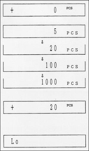
10 Piece Counting Mode
Step 1: Press the U key to switch the display to Piece Counting Mode (see Weighing Unit Initialisation page 11).
Step 2: Press the F key until the desired count value is displayed, 5, 20, 100 or 1000 pcs.
Step 3: Count out the same number of sample pieces as you selected in Step 2, and place them on the weighing pan.
Step 4: Press the TARE key to memorise the number of sample pieces and their unit weight. The display will flash until the balance has memorised this data.
Step 5: Proceed with piece counting.
Step 6: If the display shows a "Lo" message when pressing the TARE key, the unit weight of the sample pieces is less than the balance can detect.
The minimum weight of each sample piece required to establish piece counting is as follows:
KERN 434-23 |
|
0.01 g |
KERN 434-33 |
|
0.01 g |
KERN 434-37 |
|
0.1 g |
434-SH-e-9710 |
13 |
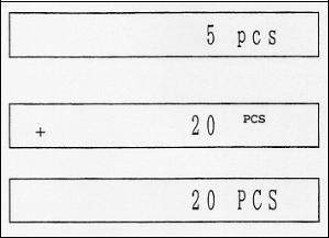
10.1Removing establishment of the standard unit weight for piece counting
This unique function of the KERN 434 series is used to easily increase the number of pieces of sample used as your piece counting standard without taking the time to count out each standard sample separately. This is important because the greater the number of sample pieces used to set your standard, the more accurate an precise your piece counting will be.
Step 1: Establish the standard number of sample pieces and unit weight at 5 PCS, for example, by following the procedure on the previous page.
Step 2: Place 15 more sample pieces on the weighing pan. The display will show that there are 20 pieces on the pan.
Step 3: Leave the 20 pieces on the weighing pan and press the F key until 20 PCS appears on the display.
Step 4: Press the Tare key to memorise the new number of sample pieces and the new unit weight.
Step 5: Follow the same procedure to increase the standard to 100 or 1000 pieces.
Note: The key is to let the balance do the counting for you when establishing the standard. For example, count out 20 pieces by yourself and set the standard at 20 pieces. Use the piece counting mode to count up to 100 pieces and set the new standard at 100 pieces. Then use the piece counting mode again to count up to 1000 pieces and set the new standard again at 1000 pieces.
14 |
434-SH-e-9710 |
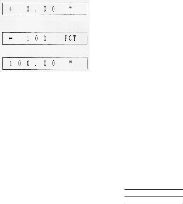
11 Percent Mode
Target weight:
Step 1: Continuously press the U key until "%" appears.
Step 2: Place a sample of the ideal 100% weight on the weighing pan.
Step 3: Press the F key to memorise the 100% weight. Make certain that """ sign appears when entering a sample. Press the TARE key if the """ sign does not appear.
Step 4: Percent mode procedure is complete when "100.00%" appears. Proceed with percent weighing by placing a new sample on the weighing pan. Percentage display is 100.00& for KERN 434-23, KERN 434-33 and KERN 434-37.
The minimum weight of the 100% sample required to establish percent weighing is as follows:
KERN 434-23 |
|
1 g |
KERN 434-33 |
|
1 g |
KERN 434-37 |
|
10 g |
11.1Weighing Mixture Mode
This mode is used when you want to mix two sample together. For instance when you add sample B to sample A to make a 100% mixture sample.
Sample B 40 %
Sample A 60 %
434-SH-e-9710 |
15 |
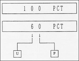
Step 1: First, memorise sample A to be the 100 % weight by using the percent mode procedure above.
Step 2: Reset sample A at 60 % weight by pressing the U and P keys.
Step 3: Add sample B to sample A until the 100 % weight is reached.
16 |
434-SH-e-9710 |

12 Adjusting Introduction
Adjusting of KERN 434 series precision balances is required at initial installation, any time the balance is moved or bumped, whenever the ambient temperature changes by more than 3° C, and additionally every 30 days or so. Adjusting is necessary for two main reasons. First, with time and use, mechanical deviations can occur. Secondly, the weight of a mass in one location or under a certain set of conditions will not always be the same at a different location or under a different set of conditions.
There are a number of adjusting procedures that will need to be done during the life of a KERN 434 series balance. They are briefly explained below. The actual adjusting procedures are contained throughout this manual (see Table of Contents page 2).
Linearity Adjusting: The purpose of Linearity Adjusting is to create a straight line from Zero to the Full Capacity Scale Value to that the balance will display accurate weighing results at all values in between. On the graph below, the Y-axis represents the "true weight" of a mass on the weighing pan and the X-axis represents the weight displayed by the balance. An accurate mass of any weight value will be plotted on a linear (straight line) path from zero to the maximum capacity. However, although a straight line will be generated by Linear Adjusting, this line must be correctly placed by the balance during Span Adjusting (see Linearity Adjusting page 41).
Span Adjusting: With Span Adjusting, we are shifting the straight line generated during Linearity Adjusting by giving it the Zero Load Value and the full capacity adjusting mass value as reference points (see Span Adjusting page 43).
434-SH-e-9710 |
17 |
Temperature Compensation Adjusting: The KERN 434 Mechanical Unit operates by a force coil moving inside a permanent magnet. A change in ambient temperature causes a change in the temperature of the Mechanical Unit, in turn altering the characteristics of the magnet. Unless this is compensated for, it will cause sensitivity drift problems. KERN 434 balances use a transistor temperature sensor in the Mechanical Unit to detect changes in temperature. The temperature compensation settings, which match the temperature characteristics of the Mechanical Unit sensor, are stored in Electronic Erasable Programmable Read Only Memory (EEPROM).
All KERN 434 series balances undergo a Temperature Compensation Adjusting at the factory before shipment. At that time all temperature compensations settings are programmed into EEPROM. Therefore, it is not necessary to perform this adjusting regularly to avoid sensitivity drift problems.
EEPROM: If the EEPROM is lost due to a component replacement or short circuit, all adjusting data is cleared. If this happens, the EEPROM must be reinitialised. Reinitialisations of the EEPROM must always be followed by Linearity and Span Adjustings. Depending the user’s needs, a Temperature Compensation Adjusting may also be necessary (see Initialisation of EEPROM, page 39).
18 |
434-SH-e-9710 |

13 Inner A /D Counter Check Mode
Many of the maintenance procedures contained in this manual require adjustments to the Inner A / D Counter Dip Switch, hereby referred to as Dip Switch, located on the Display P.C.B. (MJ-1A).
The Check Modes needed to perform the repair procedures contained in this manual are found below. When a Dip Switch adjustment is required, simply flip the switches so that they correspond to the appropriate Modes below.
|
1 |
2 |
3 |
|
|
4 |
|
||
|
|
|
|
|
|
|
|
|
|
Check 0 Mode |
ν |
|
ν |
|
ν |
|
ν |
|
Off |
(Normal Weighing) |
|
|
|
|
|
|
|
|
On |
|
|
|
|
|
|
|
|
||
|
|
|
|
|
|
|
|
|
|
|
1 |
2 |
|
|
3 |
|
|
4 |
|
|
|
|
|
|
|
|
|
|
|
|
|
Check 1 Mode |
ν |
|
|
|
ν |
|
|
ν |
|
Off |
|
|
|
|
|
|
|
|
|
|
|
(A/D Count Data) |
|
|
ν |
|
|
|
|
|
|
On |
(A/D Counter Range 0000000 - 3884160) |
|
|
|
|
|
|
|
|
|
|
|
|
|
|
|
|
|
|
|
|
|
434-SH-e-9710 |
19 |
|
1 |
2 |
3 |
|
|
4 |
|
||
|
|
|
|
|
|
|
|
|
|
Check 2 Mode |
ν |
|
ν |
|
|
|
ν |
|
Off |
|
|
|
|
|
|
|
|
|
|
(Temperature Compensation Data) |
|
|
|
|
ν |
|
|
|
On |
(A/D Counter Range 180000 - 220000) |
|
|
|
|
|
|
|
|
|
|
|
|
|
|
|
|
|
|
|
|
1 |
2 |
3 |
|
|
4 |
|
||
|
|
|
|
|
|
|
|
|
|
Check 3 Mode |
ν |
|
|
|
|
|
ν |
|
Off |
|
|
|
|
|
|
|
|
|
|
(Linearity Data) |
|
|
ν |
|
ν |
|
|
|
On |
(A/D Counter Range 0000000 - 3884160) |
|
|
|
|
|
|
|
|
|
|
|
|
|
|
|
|
|
|
|
20 |
434-SH-e-9710 |
14 Disassembly / Assembly
14.1Removing the Top Case
Step 1: Unplug the AC adapter from the balance.
Step 2: Remove the weighing pan and the pan support.
Step 3: Loosen a forehead screw toward the display keyboard and screws on rear side of the balance.
Step 4: Gently lift off the top cover, flipping it to the right.
Do not jerk the connecting cable.
Step 5: Disconnect all cables inside the balance.
434-SH-e-9710 |
21 |

14.2Removing the Mechanical Unit
Step 1: Loosen 3 screws on the bottom of the balance.
Step 2: Gently lift the Mechanical Unit box from the bottom case.
Step 3: Slowly place this Mechanical Unit box a flat surface and loosen 4 screws on top of this box.
Step 4: Open this box, then the Mechanical Unit will be exposed.
22 |
434-SH-e-9710 |
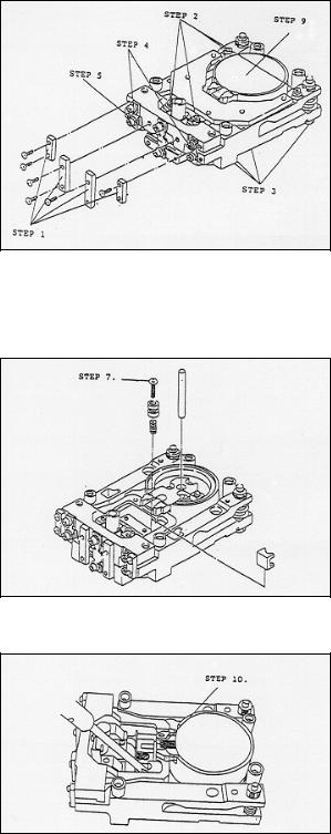
14.3Mechanical Unit Disassembly
Step 1: Attach the appropriate KERN 434 Jig Set (the beam Jig and the beamsuspension Jig) - see the Jig Set page 21.
Step 2: Loosen 4 screws on the upper plate bearing assembly and remove it.
Step 3: Loosen 4 screws on the lower plate bearing assembly and remove it.
Step 4: Loosen 4 screws for removing vertical plate springs.
Step 5: Loosen 2 screws on bottom of the balance weight and remove it.
Step 6: Loosen 4 screws for removing a coupling link.
Step 7: Loosen a screw on top of the beam positioning and remove it.
Step 8: Make certain that the beam assembly, the suspension assembly and the mechanical unit base will be disassembled separately.
Step 9: Remove the magnet lid.
Step 10: Unsolder the short wire attached on the beam
Step 11: Remove the Force Coil Bobbin from the beam. We recommend that you should wear gloves when handling the Force Coil Bobbin.
434-SH-e-9710 |
23 |
 Loading...