


7-Inch WIDE SCREEN MONITOR-RECEIVER
KVT-M700
INSTRUCTION MANUAL
Take the time to read through this instruction manual.
Familiarity with installation and operation procedures will help you obtain the best performance from your new monitor-receiver.
For your records
Record the serial number, found on the back of the unit, in the spaces designated on the warranty card, and in the space provided below. Refer to the model and serial numbers whenever you call upon your KENWOOD dealer for information or service on the product.
Model KVT-M700 Serial number
© PRINTED IN JAPAN B64-2134-00/01 (K)(DT)
Contents
Before Use |
............................................................4 |
•Safety Precautions
•About RDS
Monitor Control Function |
....................................5 |
•Opening the Monitor
•Closing the Monitor
•Power Off
•Switching the Monitor’s Picture
•Switching the Screen Mode
•Switching the AV Output
•Switching to the Angle/Screen Control Screen
•Turning the Monitor Picture Off
Angle Control Screen
•Angle Control Screen
•Adjusting the Angle Position [ANGLE]
•Adjusting the Slide Position [SLIDE]
•Automatic Open/Close [AUTO OPEN-CLOSE]
•Switching to the Screen Control Screen
•Exit the Angle Control Screen
Screen Control Screen
•Adjusting the Picture Quality
•Auto Dimmer [DIM]
•Switching to the Angle Control Screen
•Exit the Screen Control Screen
Menu Function ..................................................... |
8 |
Menu Screen
•Selecting the Menu Screen
•Selecting the Setup Menu Screen
•Selecting the Sound Control Menu Screen
•Selecting the External Display Control Screen
•Selecting the Sensor Box Control Screen
•Exit the Menu Screen
Setup Function |
.....................................................9 |
Setup Menu Screen
•Selecting the Touch Panel Adjustment Screen
•Selecting the AV Setup Screen
•Selecting the Clock Adjustment Screen
•Selecting the System Setup Screen
•Selecting the Code Security Screen
Clock Adjustment Screen
•Synchronize Clock [SYNC]
•Manual Clock Adjustment [CLOCK]
•Exit the Clock Adjustment Screen
Code Security Screen
•Security Code
•Exit the Code Security Screen
Touch Panel Adjustment Screen
•Adjusting the Touch Position
AV Setup Screen
•Setting the AV IN-1 Mode [AV-IN1]
•Setting the AV IN-2 Mode [AV-IN2]
•Setting the RGB Mode [RGB]
•Setting the the AV Output Mode [AV-OUT]
•Exit the AV Setup Screen
System Setup Function..................................... |
12 |
System Setup Screen
•Touch Sensor Tone [BEEP]
•On Screen Display [ON SCREEN]
•Disabled System Indicator [DSI]
•Switching the Setup Screen -1 and 2
•Selectable Illumination [KEY ILLUMI]
•Key Indicator Color [KEY INDICATOR]
•Navigation Announcement [NAV INTERRUPTION]
•Sound Attenuate [NAV GUIDE]
•Exit the System Setup Screen
Sound Control Function .................................... |
14 |
Sound Control Menu Screen
•Selecting the Audio Setting Screen
•Selecting the System Es Setting Screen
•Selecting the Speaker Select Screen
•Selecting the Tone Control Screen
Audio Setting Screen
•Balance and Fader [BAL/FAD]
•Loudness [LOUD]
•B.M.S. (Bass Management System) [AMP BASS]
•B.M.S. Frequency Offset [AMP FREQ]
•Volume Offset
•Switching the Audio Setting Screen -1 and 2
•System Q [SYSTEM Q]
•System Q Ex [SYSTEM QEx]
•Dual Zone System [2 ZONE]
•Exit the Audio Setting Screen
Speaker Select Screen
•Speaker & Woofer Setting
•Exit the Speaker Select Screen
Tone Control Screen
•Tone Control (System QEx set to OFF)
•Tone Control (System Q Es set to ON)
•Switching to the Tone Control Screen -1 and 2
•Exit the Tone Control Screen
System Es Setting Screen |
|
• System Es |
|
• Exit the System Es Setting Screen |
|
Source Control Function |
|
(Common operation) ......................................... |
18 |
•Displaying the On Screen Control
•Changing the Audio Source Mode
•Volume
•Attenuator
•Loudness
•Non-fading Output
•Switching to the Menu Screen
•Changing the Function Buttons
•Changing the Background Mode for the Control Screen
•TEL Mute
FM/AM Tuner Control Function ....................... |
20 |
•Selecting the FM band
•Selecting the AM band
•Tuning
•Station Preset Memory
•Preset Tuning
•Auto Memory Entry
•Seek Mode
•CRSC
•Traffic Information
•Switching Display
•Switching to the FM/AM List Screen
•Switching to the PTY Search Screen
•Switching to the Name Set Screen
•FM/AM List Screen
•PTY Search Screen
2
AV Control Function .......................................... |
23 |
•Selecting the On Screen Control
•Selecting the Preset Band TV1 and TV2
•Selecting the Video Input
•Seek Mode
•Selecting the Channel
•Station Preset Memory
•Auto Memory Entry
•Recalling a Preset Station
•Switching to the TV List Screen
•Switching to the Name Set Screen
•TV List Screen
CD Player Control Function............................... |
25 |
•Pause and play
•Fast Forwarding and Reversing
•Track Search
•Track Repeat
•Track Scan
•Random Play
•Switching Display
•Switching to the Name Set Screen
Disc Changer Control Function......................... |
26 |
•Pause and play
•Fast Forwarding and Reversing
•Track Search
•Album Search
•Track Repeat
•Album Repeat
•Track Scan
•Random Play
•Magazine Random Play
•Switching Display
•Switching to the Disc List Screen
•Switching to the Name Set Screen
•Disc List Screen
Name Set Function ............................................ |
28 |
Station Name Preset (SNPS)/
Disc Name Preset (DNPS)
Other Option Control Function......................... |
29 |
Weather Band Tuner Control |
|
• Selecting the Channels |
|
SIRIUS Tuner Control |
|
• Selecting the Preset Band |
|
• Selecting the Channel |
|
• Station Preset Memory |
|
• Seek Mode |
|
• Channel Scan |
|
• Channel Search |
|
• Switching to the Information Screen |
|
External Display Control |
|
• Switching the Display |
|
• Exit the External Display Control Screen |
|
Sensor Box Control |
|
• Setting the Menu |
|
• Exit the Sensor Box Control Screen |
|
Remote Control Function.................................. |
34 |
Installation.......................................................... |
36 |
Troubleshooting Guide...................................... |
43 |
Specifications ..................................................... |
46 |
The illustrations of the display and the panel appearing in this manual are examples used to explain more clearly how the controls are used. Therefore, what appears on the display in the illustrations may differ from what appears on the display on the actual equipment, and some of the illustrations on the display may represent something impossible in actual operation.
3
Before Use
Safety Precautions
2WARNING
To prevent injury and/or fire, take the following precautions:
•Ensure that the unit is securely installed. Otherwise it may fly out of place during collisions and other jolts.
•When extending the ignition, battery or ground wires, make sure to use automotive-grade wires or other cables with an area of 0.75mm2 (AWG18) or more to prevent wire deterioration and damage to the wire coating.
•To prevent short circuits, never put or leave any metallic objects (e.g., coins or metal tools) inside the unit.
•If the unit starts to emit smoke or strange smells, turn off the power immediately and consult your Kenwood dealer.
•Do not touch the liquid crystal fluid if the LCD is damaged or broken due to shock. The liquid crystal fluid may be dangerous to your health or even fatal.
If the liquid crystal fluid from the LCD contacts your body or clothing, wash it off with soap immediately.
2CAUTION
To prevent damage to the machine, take the following precautions:
•Make sure to ground the unit to a negative 12V DC power supply.
•Do not open the top or bottom covers of the unit.
•Do not install the unit in a spot exposed to direct sunlight or excessive heat or humidity. Also avoid places with too much dust or the possibility of water splashing.
•Do not subject the faceplate to excessive shock, as it is a piece of precision equipment.
•When replacing a fuse, only use a new one with the prescribed rating. Using a fuse with the wrong rating may cause your unit to malfunction.
•To prevent short circuits when replacing a fuse, first disconnect the wiring harness.
•Do not use any screws except for the ones provided. The use of improper screws might result in damage to the main unit.
•You cannot view video pictures whilst the vehicle is moving. To enjoy TV/video pictures, find a safe place to park and engage the parking brake.
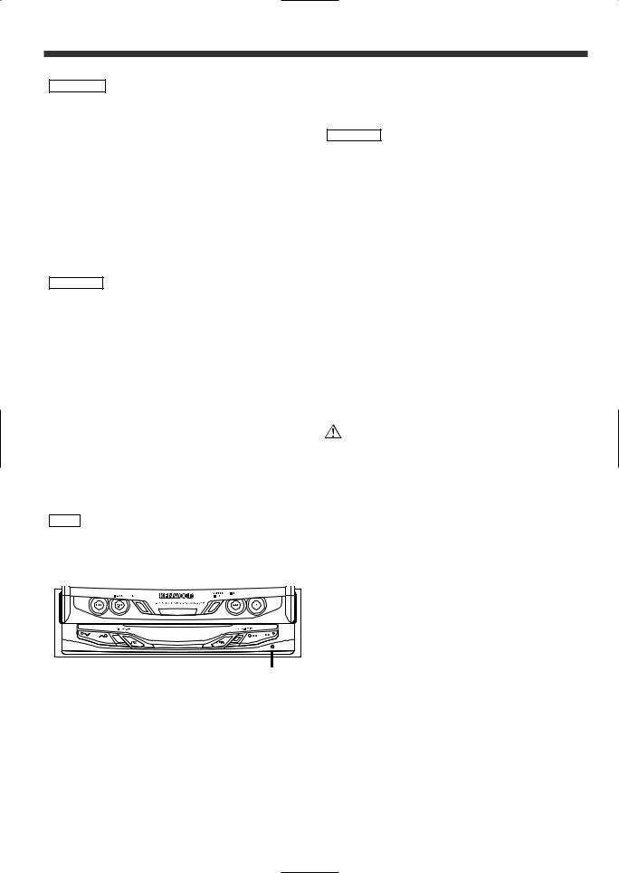
NOTE
•If you experience problems during installation, consult your Kenwood dealer.
•If the unit does not seem to be working right, try pressing the reset button first. If that does not solve the problem, consult your Kenwood dealer.
Reset button
•We recommend the use of the Security Code function (see p. 10) to prevent theft.
Cleaning the Unit
If the faceplate of this unit is stained, wipe it with a dry soft cloth such as a silicon cloth.
If the faceplate is stained badly, wipe the stain off with a cloth moistened with neutral cleaner, then wipe neutral detergent off.
2CAUTION
Applying spray cleaner directly to the unit may affect its mechanical parts. Wiping the faceplate with a hard cloth or using a volatile liquid such as thinner or alcohol may scratch the surface or erases characters.
Screen brightness during low temperatures
When the temperature of the unit falls such as during winter, the liquid crystal panel's screen will become darker than usual. Normal brightness will return after using the monitor for a while.
IMPORTANT INFORMATION
About the disc changer/CD player to be connected:
To connect a disc changer having the "O-N" switch to this unit, set the "O-N" switch to "N".
To connect a disc changer having no "O-N" switch to this unit, the converter cord CA-DS100 and/or switching adapter KCA-S210A are required as options.
A disc changer doesn't work when it is connected without using these options.
If a model with no "O-N" switch is connected, some unavailable functions and information that cannot be displayed are generated.
Note that none of the KDC-C100, KDC-C302, C205, C705, and non-Kenwood CD changers can be connected.
You can damage both your unit and the CD changer if you
connect them incorrectly.
FCC WARNING
This equipment may generate or use radio frequency energy. Changes or modifications to this equipment may cause harmful interference unless the modifications are expressly approved in the instruction manual. The user could lose the authority to operate this equipment if an unauthorized change or modification is made.
About RDS
RDS (Radio Data System)
RDS is a service used by radio stations to transmit data outside normal radio broadcast signals.
When an RDS station is received, you can immediately find out what kind of data is being transmitted by looking at the program service name, which appears in the display after the frequency.
The RDS indicator turns on when an RDS station is being received.
Alarm
When an emergency transmission (announcing disasters, etc.) is made, the current function will be interrupted to allow the warning to be received under the following conditions:
during tuner reception, or when the Traffic Information function is turned on.
4
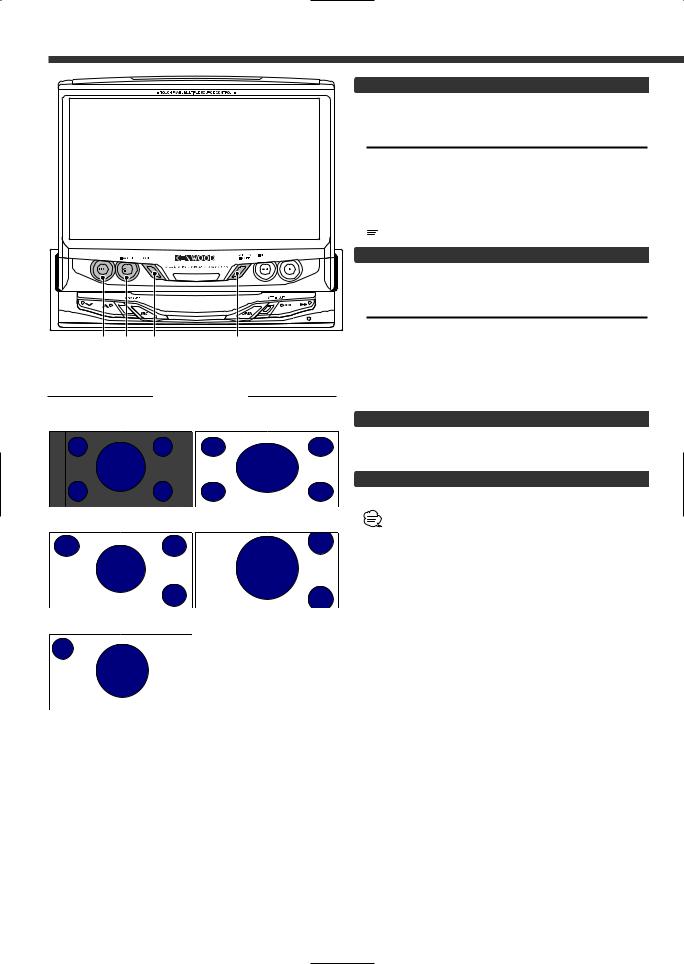
Monitor Control Function
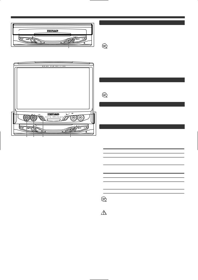
Opening the Monitor
1 Set the vehicle’s parking brake.
2 |
Press the [OPEN] button. |
|
The monitor will open. |
|
• The gear shift lever or other parts may interfere with the |
OPEN |
monitor when it opens. If so, move the gear shift lever |
(being sure to do so safely) before operating the set. (The |
|
|
monitor is drawn back in automatically if it cannot be |
|
opened normally due to an obstacle.) |
|
• The monitor cannot be opened unless the parking brake is |
|
set. |
|
• The position to which the monitor slides or angle when the |
|
power is turned on can be set. (Refer to the angle control |
|
screen on (Page 7). |
Closing the Monitor
Press the [OPEN] button.
The monitor will close.
The monitor cannot be closed unless the parking brake is set.
Power Off
Press the [SRC] button for at least 1 second.
|
|
Power On |
|
|
|
Press the [SRC] button. |
|
|
|
Switching the Monitor’s Picture |
|
|
|
Press the [V.SEL] button. |
|
|
|
Each time the button is pressed the monitor’s picture |
|
FNC V.SEL MODE |
OPEN |
switches as follows: |
|
|
|
During the KTC-V500N is not connected: |
|
|
|
Display |
Picture |
|
|
"VD 1" |
Video 1 (AV IN1 setting during “VD”) |
|
|
"VD 2" |
Video 2 (AV IN2 setting during “VD”) |
|
|
"NAV" |
RGB (from I/F terminal: RGB setting during |
|
|
|
“ON”) |
|
|
During the KTC-V500N is connected: |
|
|
|
Display |
Picture |
|
|
"VD 1" |
Video 1 (AV-IN1 setting during “VD”) |
|
|
"VD 2" |
Video 2 (AV IN2 setting during “VD”) |
|
|
"NAV" |
RGB (from I/F terminal: RGB setting during |
|
|
|
“ON”) |
|
|
"ch" |
Television |
• For “AV IN” and “RGB” setting, refer to <AV Setup Screen>. (Page 11).
• The "NAV", "VD 1" and "VD 2" displays can be changed by the <AV Setup Screen>.
You cannot view television and video pictures whilst the vehicle is moving. To enjoy television and video pictures, find a safe place to park and engage the parking brake.
5
Monitor Control Function
FNC V.SEL MODE SCREEN
|
Screen Mode |
• NORMAL |
• FULL |
;;;yyy ;;;yyy
;;;yyy ;;;yyy
• JUST |
• ZOOM |
;;;yyy
 ;;yy
;;yy
• CINEMA
;;;yyy
 ;;yy
;;yy
Switching the TV/Video Screen Mode
Press the [MODE] button.
Each time the button is pressed the screen mode switches as follows:
Display Setting
"FULL" |
Full screen mode |
"ZOOM" |
Zoom screen mode |
"JUST" |
Just screen mode |
"CINEMA" |
Cinema screen mode |
"NORMAL" |
Normal screen mode |
 You cannot operate when the navigation picture is displayed.
Switching the AV Output
Press the [V.SEL] button for at least 1 second.
Each time the button is pressed for at least 1 second the AV output switches as follows:
Display Setting
"VIDEO1" |
Picture/sound input from the AV IN |
1 |
|
termina |
|
"VIDEO2" |
Picture/sound input from the AV IN |
2 |
|
terminal |
|
"TV" |
Picture/sound of the television |
|
|
(During the KTC-V500N is connected) |
|
Switching to the Angle/Screen Control Screen
Press the [SCREEN] button.
( Page 7)
Turning the Monitor Picture Off
Press the [SCREEN] button for at least 1 second.
The picture reappears when the one of the SCREEN, MODE, V.SEL or FNC buttons is pressed.
6
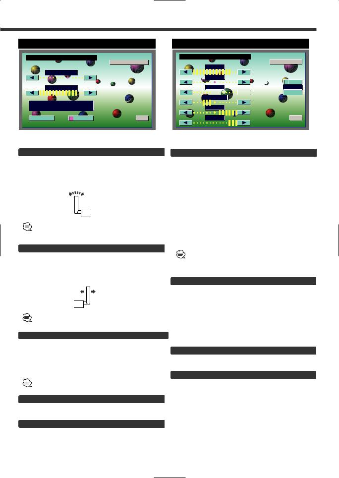
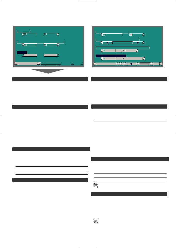
Angle Control Screen
A N G L E C T R L
S C
A N G L E
S L I D E
A U T O
O P E N - C L O S E
O N |
O F F |
Screen Control Screen
S C R E E N C T R L
A N G L E
B R T
 T I N
T I N

 O N C O L D I M


 OFF
OFF
C O N T B L K
D I M  O K
O K
Adjusting the Angle Position [ANGLE]
The monitor slants back one step:
Touch the [ 3 ] button.
The monitor slants forward one step:
Touch the [ 2 ] button.
•The angle can be adjusted in 9 steps.
•The next time the monitor is opened it stops at the set location.
Adjusting the Slide Position [SLIDE]
The monitor to the front:
Touch the [ 3 ] button.
The monitor to the back:
Touch the [ 2 ] button.
The next time the monitor is opened it stops at the set location.
Automatic Open/Close [AUTO OPEN-CLOSE]
Touch |
Setting |
[7ON] |
Switch the ACC on/off to open/close the |
|
monitor |
[7OFF] |
Use the OPEN button to open/close |
the monitor |
|
If the shift lever or other parts of the vehicle interfere with the monitor when it opens, select "OFF".
Switching to the Screen Control Screen
Touch the [SCREEN] button.
Exit the Angle Control Screen
Touch the [OK] button.
Adjusting the Picture Quality
Item |
Touch |
Setting |
BRT |
[ 3 ] |
Brighter screen |
|
[ 2 ] |
Darker screen |
TIN |
[ 3 ] |
Stronger green level |
|
[ 2 ] |
Stronger red level |
COL |
[ 3 ] |
Deeper color |
|
[ 2 ] |
Paler color |
CONT |
[ 3 ] |
Stronger contrast |
|
[ 2 ] |
Less contrast |
BLK |
[ 3 ] |
Less black level |
|
[ 2 ] |
Stronger black level |
DIM |
[ 3 ] |
Brighter screen |
|
[ 2 ] |
Darker screen |
•The [ TIN ] and [ COL ] cannot be adjusted for the navigation picture or the control screen.
•Separate picture quality settings can be stored for the television, video, control screens and navigation screens.
Auto Dimmer Function On/Off [DIM]
|
|
Touch |
Setting |
|
|
[7ON] |
The [DIM] level can be adjusted. Also, when |
|
|
|
the area around the monitor dark it's at the |
|
|
|
brightness level set by the [DIM]. |
|
|
[7OFF] |
The [DIM] items can’t be adjusted. Also, |
|
|
|
even if the area around the monitor is dark, |
|
|
|
it can’t be changed from the brightness set |
|
|
|
|
|
|
|
by [BRT]. |
Switching to the Angle Control Screen
Touch the [ANGLE] button.
Exit the Screen Control Screen
Touch the [OK] button.
7

Menu Function
|
|
|
|
On Screen Control |
|
|
|
|
|
|
|
|
|
|
|
|
|
|
|
|
|
|||||||
|
|
|
|
|
|
|
|
|
Menu Screen |
|
|
|
|
|||||||||||||||
|
|
|
|
|
|
|
|
|
|
|
|
|
|
|
|
|
|
|
|
|
|
|
|
|
|
|
|
|
|
|
|
|
|
|
|
|
|
|
|
|
|
|
|
|
|
|
|
M E N U |
|
|
1 2 : 0 0 |
|
|||||
|
|
|
|
|
|
|
|
|
|
|
|
|
|
|
|
|
|
|
|
|
|
|
|
|
|
|
||
|
|
|
|
|
|
|
|
|
|
|
|
|
|
S O U N D |
S E T U P |
|
||||||||||||
|
|
|
|
|
|
|
|
|
|
|
|
|
|
|
|
|
T U N E R |
|
||||||||||
|
|
|
|
|
|
|
|
|
|
|
|
|
|
|
|
|
|
|
|
|
|
|
|
|
|
|
||
|
|
|
|
|
|
|
|
|
|
|
|
|
|
|
|
T O U C H |
|
A V |
I / F |
|
||||||||
|
|
|
|
|
|
|
|
|
|
|
|
|
|
|
|
|
|
|
|
|
|
|
|
|||||
|
|
|
|
|
|
|
|
|
|
|
|
|
|
|
|
C L O C K |
|
|
S Y S T E M |
|
|
|
||||||
|
|
|
|
|
|
|
|
|
|
|
|
|
|
|
|
|
|
|
|
|
|
|
|
|
|
|
||
SRC |
A M |
|
|
F M |
|
|
|
|
|
|
|
|
|
|
|
|
|
|
|
|||||||||
|
|
|
F M |
3 |
P |
1 |
1 0 8 |
. 5 |
|
M Hz |
|
|
|
|
C O D E |
|
|
|
|
|
|
|
|
|
|
|||
|
|
|
F M - I N F O |
|
|
|
|
|
|
|
|
|
|
|
|
|
|
|
|
|
|
|
|
|
|
|||
P 1 P 2 P 3 P 4 P 5 P 6


 S O U R C E


FNC
Control Screen
|
|
T I |
|
|
|
|
|
|
|
M E N U |
|
|
|
1 2 : 0 0 |
|
|
|||||||||||||||
|
|
|
|
|
|
|
|
|
|
|
|
|
|
|
|
|
|
|
|
|
|
|
|
|
|
|
|
|
|
|
|
|
|
|
|
|
|
|
|
|
|
|
|
|
|
T U N E R |
|
||||||||||||||||
|
|
|
|
|
|
|
|
|
|
|
|
|
|
|
|
|
|
|
|
|
|
|
|
||||||||
|
|
|
|
|
|
|
|
|
|
|
|
|
|
|
|
|
|
|
|
|
|
|
|
|
|
|
|
|
|
||
|
|
|
|
|
|
|
|
F M 3 P 1 |
|
9 2 . 5 M Hz |
|
||||||||||||||||||||
|
|
|
|
|
|
|
|
|
F M - I N F O |
|
|
|
|
|
|
|
|
|
|
|
|
||||||||||
|
|
|
ATT |
|
|
|
|
|
|
|
|
|
|
|
|
|
|
|
|
|
|
||||||||||
|
|
|
|
|
|
|
|
|
|
|
|
|
|
|
|
|
|
|
|||||||||||||
|
|
|
LOUD |
|
|
|
|
|
|
|
|
|
|
|
|
||||||||||||||||
|
|
|
|
|
|
|
|
|
|
|
|
|
|
|
|
|
|
LIST |
|
|
|
|
|
|
|
|
|
|
|
|
|
|
|
|
|
|
|
|
|
|
|
|
|
|
|
|
|
|
|
|
|
|
|
|
|
|
|||||||
|
|
|
|
|
A M |
|
|
|
|
|
|
|
|
|
|
|
|
F M |
|
|
|
|
|
||||||||
INFO |
PTY |
|
P 1 P 2 P 3 P 4 P 5 P 6 |
8
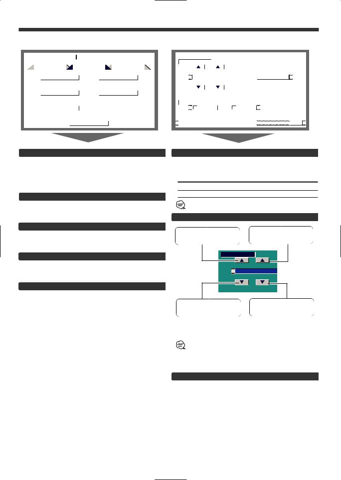
Setup Function
|
|
|
|
|
Setup Menu Screen |
|
|
|
|
|
Clock Adjustment Screen |
|
|||||||||||||||||||||||||
|
|
|
|
|
|
|
|
|
|
|
|
|
|
|
|
|
|
|
|
|
|
|
|
|
|
|
|
|
|
|
|
|
|
|
|
|
|
|
|
|
|
|
|
|
|
|
|
|
|
|
|
|
|
|
|
|
|
|
|
|
|
|
|
|
|
|
|
|
|
|
|
|
|
|
|
|
|
|
|
|
|
|
|
M E N U |
|
|
1 2 : 0 0 |
|
|
|
|
|
|
|
|
|
|
|
|
|
|
|
|
|
|
|
|
|
|||||
|
|
|
|
|
|
|
|
|
|
|
|
|
|
|
|
|
|
|
|
|
|
|
|
|
|
|
|
|
|
|
|
|
|
|
|
|
|
|
|
|
S O U N D |
|
S E T U P |
|
T U N E R |
|
|
|
|
|
|
|
|
|
|
|
|
|
|
|
|
|
|
|
|
||||||||||
|
|
|
|
|
|
|
|
|
|
|
|
|
|
|
|
|
|
|
|
|
|
|
|
|
|
|
|
|
|
|
|
|
|
|
|
|
|
|
|
|
|
|
T O U C H |
|
|
A V |
I / F |
|
|
|
|
|
|
|
|
|
|
|
|
|
|
|
|
|
|
|
|
|
|
||||||
|
|
|
|
|
|
|
|
|
|
|
|
|
|
|
|
|
|
|
|
|
|
|
|
|
|
|
|
|
|
|
|
|
|
|
|
|
|
|
|
|
|
|
|
|
|
|
|
|
|
|
|
|
|
|
|
|
|
|
|
|
|
|
|
|
|
|
|
|
|
|
|
|
|
|
|
|
|
|
|
|
C L O C K |
|
|
S Y S T E M |
|
|
|
|
|
|
|
|
|
|
|
|
|
|
|
|
|
|
|
|
|
|
|
||||||
|
|
|
|
|
|
|
|
|
|
|
|
|
|
|
|
|
|
|
|
|
|
|
|
|
|
|
|
|
|
|
|
|
|
|
|
|
|
|
|
|
|
|
|
|
|
|
|
|
|
|
|
|
|
|
|
|
|
|
|
|
|
|
|
|
|
|
|
|
|
|
|
|
|
|
|
|
|
|
|
|
C O D E |
|
|
|
|
|
|
|
|
|
|
|
|
|
|
|
|
|
|
|
|
|
|
|
|
|
|
|
|
|
|
||
|
|
|
|
|
|
|
|
|
|
|
|
|
|
|
|
|
|
|
|
|
|
|
|
|
|
|
|
|
|
|
|
|
|
|
|
|
|
|
|
|
|
|
|
|
|
|
|
|
|
|
|
|
|
|
|
|
|
|
|
|
|
|
|
|
|
|
|
|
|
|
|
|
|
|
|
|
|
|
|
|
|
S O U R C E |
|
|
|
|
|
|
|
|
|
|
|
|
|
|
|
|
|
|
|
|
|
RTN |
|
|
|||||||
|
|
|
|
|
|
|
|
|
|
|
|
|
|
|
|
|
|
|
|
|
|
|
|
|
|
|
|
|
|
|
|
|
|
|
|
|
|
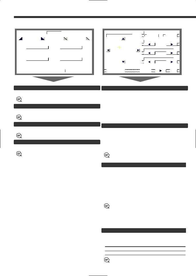
Selecting the Touch Panel Adjustment Screen
The touch panel can be adjusted if the position touched and the operation performed do not match.
Touch the [TOUCH] button.
( Page 10)
Selecting the AV Setup Screen
Touch the [AV I/F] button.
( Page 11)
Selecting the Clock Adjustment Screen
Touch the [CLOCK] button.
( Page 9)
Selecting the System Setup Screen
Touch the [SYSTEM] button.
( Page 12)
Selecting the Code Security Screen
Press the [CODE] button for at least 2 seconds.
( Page 10)
C K
2 : 0 0
To make the minutes go back.
Setting the Minutes to "00":
Touch the [RESET] button.
• Touch the [RESET] button while the minute is below "30" rounds it off, and while the minute is "30" or more rounds it up.
•This adjustment can be done when the <SYNC> is set as OFF.
Exit the Clock Adjustment Screen
Touch the [RTN] button.
Return to the setup menu screen.
Code Security Screen
|
|
|
|
|
|
|
|
|
|
|
|
|
# # # # |
1 s t |
|
|
|
||||||
|
|
|
|
|
|
|
|
|
|
|
|
1 |
|
2 |
3 |
|
|
|
|
|
|||
|
|
|
|
|
|
|
|
|
|
|
|
4 |
|
5 |
6 |
|
|
|
|
|
|||
|
|
|
|
|
|
|
|
|
|
|
|
7 |
|
8 |
9 |
|
|
|
|
|
|||
|
|
|
|
|
|
|
|
|
|
||
|
|
|
0 |
|
CLR |
||||||
|
|
|
|
|
|
|
|
|
|
|
|
S E C U R I T Y |
|
|
|
|
RTN |
|
|
|
|||
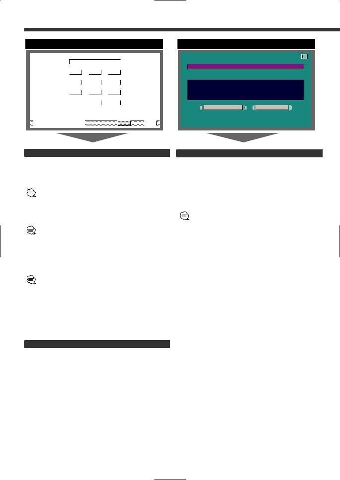
Touch Panel Adjustment Screen
T O U C H P A N E L A D J U S T
P l e a s e T o u c h
t h e C e n t e r o f
t h e B u t t o n i n t h e R i g h t - T o p C o r n e r .
C A N C E L |
R E S E T |
Security Code
Because authorization by the Security Code is required when it's removed from the vehicle, personalizing this unit is by using the Security Code is a help in preventing theft.
When the Security Code function is activated, the code can't be changed and the function can't be released.
Note, the Security Code can be set as the 4 digit number of your choice.
1Enter the Security Code
Touch the [0] — [9] button.
If you enter the wrong number, touch [CLR].The last entered number is cleared.
2Confirm the Security Code
Touch the [OK] button.
3Do the step 1 and 2 step operation, and reenter
the security code.
Return to the setup menu screen.
When the wrong Code is entered in steps 1, repeat from step 1.
Press the Reset button and when it's removed from the battery power source
1Turn the power ON.
2Do the step 1 and 2 operation, and enter the
Security Code.
The “ALL OFF” screen is displayed. The unit can be used.
Exit the Code Security Screen
Touch the [RTN] button.
Return to the setup menu screen.
Adjusting the Touch Position
The touch panel can be adjusted if the position touched and the operation performed do not match.
1Accurately touch the mark at the upper right.
2Accurately touch the mark at the lower left.
When the mark at the lower left is touched, the adjustment is completed and the system setup menu screen reappears.
• If the [CANCEL] button is touched without touching the button at the upper right, the adjustment is canceled and the screen that was set before switching to the system setup menu reappears.
•If the [CANCEL] button is touched after touching the button at the upper right, the button at the upper right reappears.
•If the [RESET] button is touched, the settings are reset to the factory defaults and the setup menu screen reappears.
10
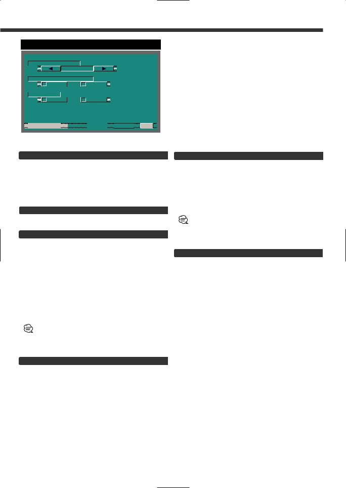
AV Setup Screen
A V - |
I N 1 |
|
|
|
|
|
|
|
|
|
|
|
|
|
|
|
|
|
|||||
|
|
|
|
V D |
|
|
|
|
N A V |
|
|
|
|
|
|
V D |
1 |
|
|
|
|||
|
|
|
|
|
|
|
|
|
|
|
|
|
|
|
|
|
|
|
|
|
|
|
|
A V - |
I N 2 |
|
|
|
|
|
|
|
|
|
|
|
|
|
|
|
|
||||||
|
|
|
V D |
|
|
|
|
A U T O |
|
|
|
|
O F F |
|
|
|
|
|
|||||
|
|
|
|
|
|
|
|
|
|
|
|
|
|
|
|
|
|
|
|
|
|
|
|
|
|
|
|
|
|
|
|
|
|
|
|
|
|
|
|
|
|
V D |
2 |
|
|
|
|
R G B - I N |
|
|
|
|
|
|
|
|
|
|
|
|
|
|
|
|
|
||||||
|
|
|
|
|
|
|
|
|
|
|
|
|
|
|
|
|
|
|
|||||
|
|
|
O N |
|
|
|
|
O F F |
|
|
|
|
|
|
N A V |
|
|
|
|||||
|
|
|
|
|
|
|
|
|
|
|
|
|
|
|
|
|
|
|
|
|
|
|
|
A V - O U T |
|
|
|
|
|
|
|
|
|
|
|
|
|
|
|
|
|||||||
|
|
|
|
A V 1 |
|
|
|
|
|
A V 2 |
|
|
|
|
T V |
|
|
|
|
|
|||
 A V I / F


 RTN
RTN
Setting the AV IN-1 Mode [AV-IN1]
Touch |
Setting |
[7NAV] |
It becomes the navigation mode setting. |
|
Operate the V.SEL button when the image |
|
from the navigation unit connected to AV |
|
IN1 terminal is shown on the monitor. |
[7VD] |
It becomes the video mode setting.Operate |
|
the V.SEL button when the image from |
|
the device connected to AV IN1 terminal is |
|
shown on the monitor. |
Select the AV-IN1 input display:
Selecting the display when this device is switched to internal AV-IN1 terminal input source.
Each time you touch the [ 2 ] or [ 3 ] button, the display switches as follows:
"VD 1"↔"VIDEO1"↔ "NAV1"↔"DVD1"↔ "VCR1"↔ "VCD1"↔"GAME1"↔"AUX1"
Setting the AV IN-2 Mode [AV-IN2]
Touch |
Setting |
[7VD] |
It becomes the video mode setting. Operate |
|
the V.SEL button when the image from the |
|
device connected to AV IN2 terminal is |
|
shown on the monitor. |
[7AUTO] |
It becomes the auto video mode setting. |
|
When the video signal input to the AV IN2 |
|
terminal, the monitor image is switched to |
|
the image of the device connected to the AV |
|
IN2 terminal. |
[7OFF] |
It becomes the OFF mode setting.Use this |
|
setting when there’s nothing connected to |
|
the AV IN2 terminal. |
Select the AV-IN2 input display:
Selecting the display when this device is switched to internal AV-IN2 terminal input source.
Each time you touch the [ 2 ] or [ 3 ] button, the display switches as follows:
"VD 2"↔"VIDEO2"↔ "NAV2"↔"DVD2"↔ "VCR2"↔ "VCD2"↔"GAME2"↔"AUX2"↔"CAMERA"
Setting the RGB Mode [ RGB]
Touch |
Setting |
[7ON] |
It becomes the RGB mode setting. Operate |
|
the V.SEL button when the image from the |
|
the navigation unit connected to I/F terminal |
|
is shown on the monitor. |
[7OFF] |
It becomes the OFF mode setting.Use this |
|
setting when there’s nothing connected to |
|
the I/F terminal. |
Select the I/F input display:
Selecting the display when this device is switched to internal I/F terminal input source.
Each time you touch the [ 2 ] or [ 3 ] button, the display switches as follows:
"NAV"↔ "DVD"↔"DVB"↔ "RGB"
Setting the AV Output Mode
Touch |
Setting |
[7AV1] |
Picture/sound from AV IN1 terminal. |
[7AV2] |
Picture/sound from AV IN2 terminal. |
[7TV] |
Picture/sound from television. |
|
(During the KTC-V500N is connected) |
Exit the AV Setup Screen
Touch the [RTN] button.
Return to the setup menu screen.
11
|
|
|
|
|
|
|
|
|
|
|
|
|
|
|
|
|
|
|
|
|
|
|
|
|
|
|
|
|
|
|
|
|
|
|
|
|
|
|
|
|
|
|
|
|
|
|
|
|
|
|
|
|
|
|
|
|
|
|
|
|
|
|
|
|
|
|
|
|
|
|
|
|
|
|
|
|
|
|
|
|
|
|
|
|
|
|
|
|
|
|
|
|
|
|
|
|
|
|
|
|
|
|
|
System Setup Screen-1 |
|
|
|
|
|
System Setup Screen-2 |
|
|
|||||||||||||||||||
|
|
|
|
|
|
|
|
|
|
|
|
|
|
|
|
|
|
|
|
|
|
|
|
|
|
|
|
|
|
|
|
|
|
|
B E E P |
|
|
|
|
|
|
|
|
|
|
|
|
|
|
|
|
|
|
|
|
|
|
|
|
|
|
||||
|
|
|
|
|
|
|
|
|
|
|
|
|
|
|
|
|
|
|
|
|
|
|
|
|
|
|
|
|
||||
|
|
|
|
|
O |
N |
|
O F F |
|
|
|
|
|
|
|
|
|
|
|
|
|
|
|
|
|
|
|
|
|
|
|
|
|
|
|
|
|
|
|
|
|
|
|
|
|
|
|
|
|
|
|
|
|
|
|
|
|
|
|
|
|
|
|
|
|
|
|
|
|
|
|
|
|
|
|
|
|
|
|
|
|
|
|
|
|
|
|
|
|
|
|
|
|
|
|
|
|
|
|
|
A U T O O N S C R E E N |
|
|
|
|
|
|
|
|
|
|
|
|
|
|
|
|
|
|
|
|
|
|||||||||
|
|
|
|
|
O |
N |
|
O F F |
|
|
|
|
|
|
|
|
|
|
|
|
|
|
|
|
|
|
|
|
|
|
|
|
|
|
|
|
|
|
|
|
|
|
|
|
|
|
|
|
|
|
|
|
|
|
|
|
|
|
|
|
|
|
|
|
|
|
|
|
|
|
|
|
|
|
|
|
|
|
|
|
|
|
|
|
|
|
|
|
|
|
|
|
|
|
|
|
|
|
|
|
|
|
|
|
|
|
|
|
|
|
|
|
|
|
|
|
|
|
|
|
|
|
|
|
|
|
|
|
|
|
|
|
|
|
|
|
|
|
|
|
|
|
|
|
|
|
|
|
|
|
|
|
|
|
|
|
|
|
|
|
|
|
|
|
D S I

 O N
O N 
 O F F
O F F
 S Y S T E M


Touch Sensor Tone [BEEP]
Setting the operation check sound (beep sound) ON/OFF.
Touch |
Setting |
[7ON] |
Touch sensor tone is turned on |
[7OFF] |
Touch sensor tone is turned off |
On Screen Display [AUTO ON SCREEN]
Touch |
Setting |
[7AUTO] |
When a button on the main unit or remote |
|
control unit is pressed, or the disc track is |
|
changed, the audio source control |
|
information is temporarily superimposed on |
|
the picture. |
[7MANU] |
When the lower canter of the screen is |
|
touched while a TV/video picture is displayed, |
|
the audio source control information is |
|
temporarily superimposed on the picture. |
Disabled System Indicator [DSI]
A red indicator (Reset button) will blink on the unit after the ignition Key switch is off , warning potential thieves.
Touch |
Setting |
[7ON] |
LED flashes. |
[7OFF] |
LED OFF. |
Switching the Setup Screen -1 and 2
Touch the [ 2 ] or [ 3 ] button.
Selectable Illumination [KEY ILLUMI]
Selecting the button illumination color as green or red.
Touch |
Setting |
[7GREEN] |
The illumination color is green. |
[7RED] |
The illumination color is red. |
Key Indicator Color [KEY INDICATOR]
Selecting the OPEN and SRC button indicator color. Touch the [ 2 ] or [ 3 ] button.
Display Setting
|
|
"SOURCE" |
The color changes according to the selected |
|
|
|
source. |
|
|
"MARS" |
Red |
|
|
"LIME" |
Green |
|
|
"SUNSET |
Red Green |
|
|
"SKY" |
Blue |
|
|
"VIOLET" |
Violet |
|
|
"AQUA" |
Blue Green |
|
|
"MOON" |
White |
|
Navigation Announcement [NAV INTERRUPTION] 
The navigation voice is output from the front speaker at navigation voice guide announcement time.
Touch |
Setting |
[7ON] |
Announcement function is on |
[7OFF] |
Announcement function is off |
This function available when the KENWOOD navigation unit is connected to the I/F terminal.
Sound Attenuate [NAV GUIDE]
The rear speaker sound is attenuate during the navigation voice output time.
Touch |
Setting |
[7ATT] |
Rear speaker attenuate function is on |
[7SOUND] |
Rear speaker attenuate function is off |
This function available when the KENWOOD navigation unit is connected to the I/F terminal.
12

Exit the System Setup Screen
Touch the [RTN] button.
Return to the setup menu screen.
13
Sound Control Function
|
|
|
|
Sound Control Menu Screen |
|
|
|
|
|
Audio Setting Screen-1 |
|
|
|
|
|
|
|
|
|
||||||||||||||||||||||||||||||
|
|
|
|
|
|
|
|
|
|
|
|
|
|
|
|
|
|
|
|
|
|
|
|
|
|
|
|
|
|
|
|
|
|
|
|
|
|
|
|
|
|
|
|
|
|
|
|
|
|
|
|
|
|
|
|
|
M E N U |
|
|
|
1 2 : |
|
|
|
|
|
|
|
|
|
|
|
|
|
|
|
|
|
|
|
|
L O U D |
|
|
|
|
|
|
|
|
|
|
|
||||||
|
|
|
|
|
|
|
|
|
|
|
|
|
|
|
|
|
|
|
|
|
|
|
|
B A L / F A D |
|
|
|
|
|
O N |
|
|
O F F |
|
|
|
|
|
|||||||||||
|
|
|
S O U N D |
|
S E T U P |
|
T U N E |
|
|
|
|
|
|
|
|
|
|
|
|
|
F |
|
|
|
|
|
|
|
|
|
|
|
|
|
|
|
|
|
|||||||||||
|
|
|
|
|
|
|
|
|
|
|
|
|
|
|
|
|
|
|
|
|
|
|
|
|
|
|
|
|
|
|
|
|
|
|
A M P |
|
B A S S |
|
|
|
|
|
|||||||
|
|
|
|
|
|
|
|
|
|
|
|
|
|
|
|
|
|
|
|
|
|
|
|
|
|
|
|
|
|
|
|
|
|
|
|
|
|
F L T |
|
|
|
|
|
|
|
|
|
||
|
|
|
|
A U D I O |
|
S Y S |
E s |
|
|
|
|
|
|
|
|
|
|
|
|
|
|
|
|
|
|
|
|
|
|
|
|
|
|
|
|
|
|
|
|
|
|
||||||||
|
|
|
|
|
|
|
|
|
|
|
|
|
|
|
|
|
|
|
|
|
|
|
|
|
|
|
|
|
|
|
|
|
|
|
A M P |
|
F R E Q |
|
|
|
|
|
|||||||
|
|
|
|
|
|
|
|
|
|
|
|
|
|
|
|
|
|
|
|
|
|
|
|
L |
|
|
|
|
|
|
|
R |
|
|
|
|
|
|
|
|
|
|
|
|
|
|
|
|
|
|
|
|
|
|
|
|
|
|
|
|
|
|
|
|
|
|
|
|
|
|
|
|
|
|
|
|
|
|
|
|
|
|
|
|
|
N M L |
|
|
|
|
|
|
|
|
|
||||
|
|
|
|
|
|
|
|
|
|
|
|
|
|
|
|
|
|
|
|
|
|
|
|
|
|
|
|
|
|
|
|
|
|
|
|
|
|
||||||||||||
|
|
|
|
S P S E L |
|
|
|
T O N E |
|
|
|
|
|
|
|
|
|
|
|
|
|
|
|
|
|
|
|
V . O F F S E T |
|
|
|
||||||||||||||||||
|
|
|
|
|
|
|
|
|
|
|
|
|
|
|
|
|
|
|
|
|
|
|
|
|
|
|
|
|
R |
|
|
|
|
|
|
O F F |
|
|
|
|
|
|
|
|
|
||||
|
|
|
|
|
|
|
|
|
|
|
|
|
|
|
|
|
|
|
|
|
|
|
|
|
|
|
|
|
|
|
|
|
|
|
|
|
|
|
|
|
|
|
|
|
|
|
|
|
|
|
|
|
|
|
|
|
|
|
|
|
|
|
|
|
|
|
|
|
|
|
|
|
|
|
|
|
|
|
|
|
|
|
|
|
|
|
|
|
|
|
|
|
|||||||
|
|
|
|
|
S O U R C E |
|
|
|
|
|
|
|
|
|
|
|
|
A U D I O |
|
|
|
|
|
|
|
|
|
|
|
|
RTN |
|
|
|
|
||||||||||||||
|
|
|
|
|
|
|
|
|
|
|
|
|
|
|
|
|
|
|
|
|
|
|
|
|
|
|
|
|
|
|
|
|
|
|
|
|
|
|
|
|
|
|
|
|
|
|
|
|
|
|
|
|
|
|
|
|
|
|
|
|
|
|
|
|
|
|
|
|
|
|
|
Balance and Fader [BAL/FAD] |
|
|
|
|
|
|
|
|
|
|
|
|
|||||||||||||||
|
|
|
|
|
|
|
|
|
|
|
|
|
|
|
|
|
|
|
|
|
|
|
|
|
|
|
|
|
|
|
|
|
|
||||||||||||||||
|
|
|
|
|
|
|
|
|
|
|
|
|
|
|
|
|
|
|
|
|
|
|
Touch |
|
|
Setting |
|
|
|
|
|
|
|
|
|
|
|
|
|
|
|
||||||||
|
|
|
|
|
|
|
|
|
|
|
|
|
|
|
|
|
|
|
|
|
|
|
|
|
|
|
|
|
|
|
|
|
|
|
|
|
|
|
|
||||||||||
|
|
|
|
|
|
|
|
|
|
|
|
|
|
|
|
|
|
|
|
|
|
|
[2]L |
|
|
The sound in the left channel is |
|
||||||||||||||||||||||
|
|
|
|
|
|
|
|
|
|
|
|
|
|
|
|
|
|
|
|
|
|
|
|
|
|
|
|
emphasized. |
|
|
|
|
|
|
|
|
|
|
|
|
|
|
|
||||||
|
|
|
|
|
|
|
|
|
|
|
|
|
|
|
|
|
|
|
|
|
|
|
|
|
|
|
|
|
|
|
|
|
|
|
|
|
|
|
|
|
|||||||||
|
|
|
|
|
|
|
|
|
|
|
|
|
|
|
|
|
|
|
|
|
|
|
[3]R |
|
|
The sound in the right channel is |
|
||||||||||||||||||||||
|
|
|
|
|
|
|
|
|
|
|
|
|
|
|
|
|
|
|
|
|
|
|
|
|
|
|
|
emphasized. |
|
|
|
|
|
|
|
|
|
|
|
|
|
|
|
||||||
|
|
|
|
|
|
|
|
|
|
|
|
|
|
|
|
|
|
|
|
|
|
|
|
|
|
|
|
|
|
|
|
|
|
|
|
|
|
|
|
|
|||||||||
|
|
|
|
|
|
|
|
|
|
|
|
|
|
|
|
|
|
|
|
|
|
|
[5]F |
|
|
The sound in the front channel emphasized. |
|
||||||||||||||||||||||
|
|
|
|
|
|
|
|
|
|
|
|
|
|
|
|
|
|
|
|
|
|
|
[∞]R |
|
|
The sound in the rear channel emphasized. |
|
|
|||||||||||||||||||||
|
|
|
|
|
|
|
|
|
|
|
|
|
|
|
|
|
|
|
|
|
|
Loudness [LOUD] |
|
|
|
|
|
|
|
|
|
|
|
|
|
|
|
||||||||||||
|
|
|
|
|
|
|
|
|
|
|
|
|
|
|
|
|
|
|
|
|
|
|
|
|
|
|
|
|
|
|
|
|
|
|
|
|
|||||||||||||
|
|
|
|
|
|
|
|
|
|
|
|
|
|
|
|
|
|
|
|
|
|
|
|
|
|
|
|
|
|
|
|
|
|
|
|
|
|||||||||||||
|
|
|
|
|
|
|
|
|
|
|
|
|
|
|
|
|
|
|
|
|
|
Compensating for low and high tones during low |
|
||||||||||||||||||||||||||
|
|
|
|
|
|
|
|
|
|
|
|
|
|
|
|
|
|
|
|
|
|
|
|||||||||||||||||||||||||||
|
|
|
|
|
|
|
|
|
|
|
|
|
|
|
|
|
|
|
|
|
|
volume. |
|
|
|
|
|
|
|
|
|
|
|
|
|
|
|
|
|
|
|
|
|
|
|
|
|||
|
|
|
|
|
|
|
|
|
|
|
|
|
|
|
|
|
|
|
|
|
|
|
Touch |
|
|
Setting |
|
|
|
|
|
|
|
|
|
|
|
|
|
|
|
||||||||
|
|
|
|
|
|
|
|
|
|
|
|
|
|
|
|
|
|
|
|
|
|
|
|
|
|
|
|
|
|
|
|
|
|
|
|
||||||||||||||
|
|
|
|
|
|
|
|
|
|
|
|
|
|
|
|
|
|
|
|
|
|
|
[7ON] |
|
|
Loudness function is turned on |
|
||||||||||||||||||||||
|
|
|
|
|
|
|
|
|
|
|
|
|
|
|
|
|
|
|
|
|
|
||||||||||||||||||||||||||||
|
|
|
|
|
|
|
|
|
|
|
|
|
|
|
|
|
|
|
|
|
|
|
[7OFF] |
|
|
Loudness function is turned off |
|
|
|||||||||||||||||||||
When the Loudness function is ON, the "LOUD" indicator is
ON in the source control screen.
B.M.S. (Bass Management System) [AMP BASS]
Adjust the bass boost level of the external amplifier using the main unit.
Touch the [ 2 ] or [ 3 ] button.
Display |
Setting |
"FLT" |
Bass boost level is flat. |
"+6dB" |
Bass boost level is low (+6dB). |
"+12dB" |
Bass boost level is mid (+12dB). |
"+18dB" |
Bass boost level is high (+18dB). |
• Refer to the catalog or instruction manual for power amplifiers that can be controlled from this unit.
• For amplifiers there are the model that can be set from Flat to +18 dB, an the model that can be set from Flat to +12 dB. When and amplifier is connected that can only be set to +12dB, even if “+18dB” is selected it won’t operate correctly.
B.M.S. Frequency Offset [AMP FREQ]
Setting the central frequency boosted by B.M.S.
Touch the [ 2 ] or [ 3 ] button.
Display |
Setting |
"NML" |
Boost with the normal central frequency. |
"LOW" |
Drop the normal central frequency 20%. |
Refer to the catalog or instruction manual for power amplifiers that can be controlled from this unit.
14
Audio Setting Screen-2
S Y S T E M |
Q |
|
|
|
|
|
|
|
|
|||||
|
|
|
|
|
T O P |
4 0 |
|
|
|
|
||||
|
|
|
|
|
|
|
|
|
|
|
|
|
|
|
S Y S T E M |
Q E x |
|
|
|||||||||||
|
|
|
O |
|
N |
|
|
|
|
O F F |
|
|
||
|
|
|
|
|
|
|
|
|
|
|
|
|||
2 Z O N E |
|
|
|
|
|
|
|
|
|
|
|
|||
|
|
|
O |
|
N |
|
|
|
|
O F F |
|
|
||
 A U D I O


 RTN
RTN
Dual Zone System [2 ZONE]
The following operation allows separate sound sources to control the output of the front and rear speakers.
Touch |
Setting |
[7ON] |
The dual zone system function is on. |
|
AV-OUT sound send to the rear speaker. |
[7OFF] |
The dual zone system function is off. |
• When the Dual Zone System is ON, there is no rear channel audio control or other effect.
• When you set the Dual zone system to ON while the nonfading preout is switched ON, the sound of the non-fading preout isn’t output.
Exit the Audio Setting Screen
Touch the [RTN] button.
Return to the sound control menu screen.
 Loading...