


795.777297
Kenmore 795.777297, 795.777197, 795.777137, 795.777127, 795.775536 Service Manual
...
CAUTION
BEFORE SERVICING THE UNIT,
READ THE SAFETY PRECAUTIONS IN THIS MANUAL.
REFRIGERATOR
SERVICE MANUAL
R
795.77192600
795.77199600
795.77194600
795.77193600
795.77196600
795.77542600
795.77549600
795.77544600
795.77543600
795.77546600
795.77552600
795.77559600
795.77554600
795.77553600
795.77556600
795.77712700
795.77713700
795.77719700
795.77729700
P/No. 3828JL8796A (Last Revision: MARCH. 2. 2006)
Model #s:

- 2 -
SAFETY PRECAUTIONS....................................................................................................................................................... 2
1. SPECIFICATIONS............................................................................................................................................................... 3
2. PARTS IDENTIFICATION................................................................................................................................................... 4
3. DISASSEMBLY.............................................................................................................................................................. 5-12
DOOR.............................................................................................................................................................................. 5-7
TO REMOVE THE DISPENSER .........................................................................................................................................7
FAN AND FAN MOTOR...................................................................................................................................................... 8
DEFROST CONTROL ASSEMBLY.................................................................................................................................... 8
LAMP.................................................................................................................................................................................. 8
CONTROL BOX-REFRIGERATOR.................................................................................................................................... 8
MULTI DUCT ...................................................................................................................................................................... 8
HOW TO REMOVE AND REINSTALL THE PULLOUT DRAWER................................................................................ 9-12
TRIM KIT ASSEMBLY AND AISASSEMBLY METHOD(795.77719, 77729 models only.............................................13-15
4. ADJUSTMENT............................................................................................................................................................. 16-17
COMPRESSOR................................................................................................................................................................ 16
PTC-STARTER................................................................................................................................................................. 16
OLP (OVERLOAD PROTECTOR).................................................................................................................................... 17
TO REMOVE THE COVER PTC.......................................................................................................................................17
5. CIRCUIT DIAGRAM.......................................................................................................................................................... 18
6. TROUBLESHOOTING................................................................................................................................................. 19-24
COMPRESSOR AND ELECTRIC COMPONENTS.......................................................................................................... 19
PTC AND OLP.................................................................................................................................................................. 20
OTHER ELECTRICAL COMPONENTS ........................................................................................................................... 21
SERVICE DIAGNOSIS CHART........................................................................................................................................ 22
REFRIGERATION CYCLE .......................................................................................................................................... 23-24
7. OPERATION PRINCIPLE & REPAIR METHOD OF ICEMAKER .............................................................................. 25-28
8. DESCRIPTION OF FUNCTION & CIRCUIT OF MICOM ........................................................................................... 29-40
CONTENTS
Please read the following instructions before servicing your refrigerator.
1. Unplug the power before handling any elctrical componets.
2. Check the rated current, voltage, and capacity.
3. Take caution not to get water near any electrical components.
4. Use exact replacement parts.
5. Remove any objects from the top prior to tilting the product.
SAFETY PRECAUTIONS
1-1 DISCONNECT POWER CORD BEFORE
SERVICING
IMPORTANT – RECONNECT ALL
GROUNDING DEVICES
All parts of this appliance capable of conducting electrical
current are grounded. If grounding wires, screws, straps,
clips, nuts or washers used to complete a path to ground
are removed for service, they must be returned to their
original position and properly fastened.
1-2 IMPORTANT NOTICE
This information is intended for use by individuals
possessing adequate backgrounds of electrical, electronic
and mechanical experience. Any attempt to repair a major
appliance may result in personal injury and property
damage. The manufacturer or seller cannot be responsible
for the interpretation of this information, nor can it assume
any liability in connection with its use.
1-3 ELECTRICAL SPECIFICATIONS
Temperature Control (Freezer Compartment)...-6°F to +8°F
Defrost Control.................Total Comp Running Time : 7 hrs
Defrost Thermostat.......................................................46°F
Electrical Rating : 115VAC, 60Hz.................................1-5 A
Maximum Current Leakage.......................................0.5 mA
Maximum Ground Path Resistance....................0.14 Ohms
Energy Consumption .....21 cu.ft. 484 kWh/yr (Energy Star)
.......................................25 cu.ft. 499 kWh/yr (Energy Star)
1-4 NO LOAD PERFORMANCE
CONTROL POSITION: MID/MID
And Ambient of: ..................70°F..................................90°F
Fresh Food, °F....................33°F to 41°F.........33°F to 41°F
Frozen Food, °F..................-4°F to +4°F..........-4°F to +4°F
Percent Running Time........35%-45%.................50°F-70°F
1-5 REFRIGERA TION SYSTEM
Minimum Compressor Capacity Vacuum ............... 20 MIN.
Minimum Equalized Pressure
@ 70°F ....................................................... 49 PSIG
@ 90°F ....................................................... 56 PSIG
Refrigerant R134a ................................................. 4.06 oz.
Compressor ..................................................... 830 BTU/hr
1-6 INSTALLATION
Clearance must be provided at top, sides and rear of the
refrigerator for air circulation.
AT TOP ......................................................................... 1 in
AT SIDES ...................................................................... 1 in
AT REAR ...................................................................... 2 in
1-7 REPLACEMENT PARTS
Relay............................................................. 6748C-0004D
Overload ....................................................... 6750C-0005P
Defrost Thermostat ...................................... 6615JB2005H
Defrost Heater ............................................. 5300JK1005D
Evaporator Fan Motor .................................. 4681JK1004A
Capacitor .................................................... 0CZZJB2012G
Compressor (Hi-Side) .................................. 2521C-A5719
Evaporator (Lo-Side) .................................... 5421JJ0006A
*5421JJ0007A
Condenser .................................................... 5403JJ1004B
Dryer ............................................................ 5851JA2008A
Condenser Fan Motor .................................. 4681JB1029D
Temperature Control .................................... 6871JB1439A
Main Control.................................................. 6871JB1423B
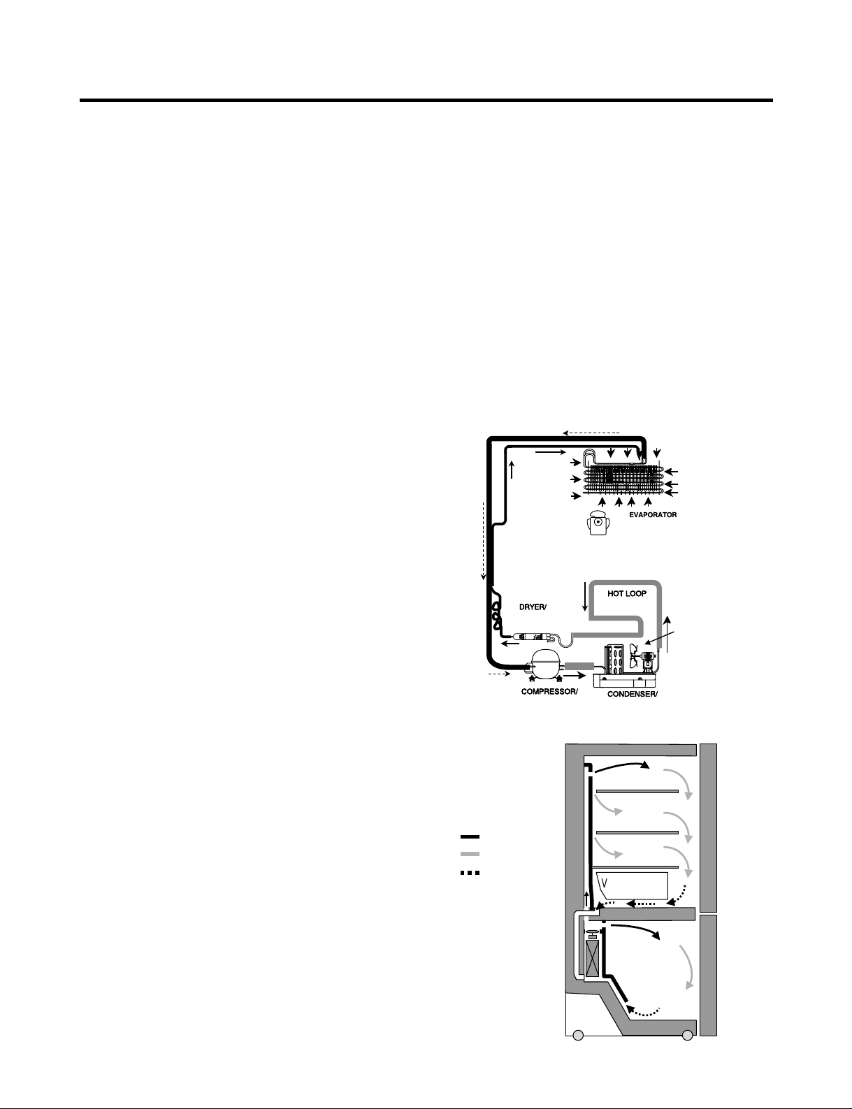
1-8 AIR FLOW / CIRCULATION D’AIR
1. SPECIFICATIONS
- 3 -
EVAPORATOR
COLD AIR
MIXED AIR
AIR RETURN TO
EVAPORATOR
FRESH FOOD
FREEZER
Ò
Vegetable box
EVAPORTOR FAN MOTOR
CONDENSER FAN MOTOR
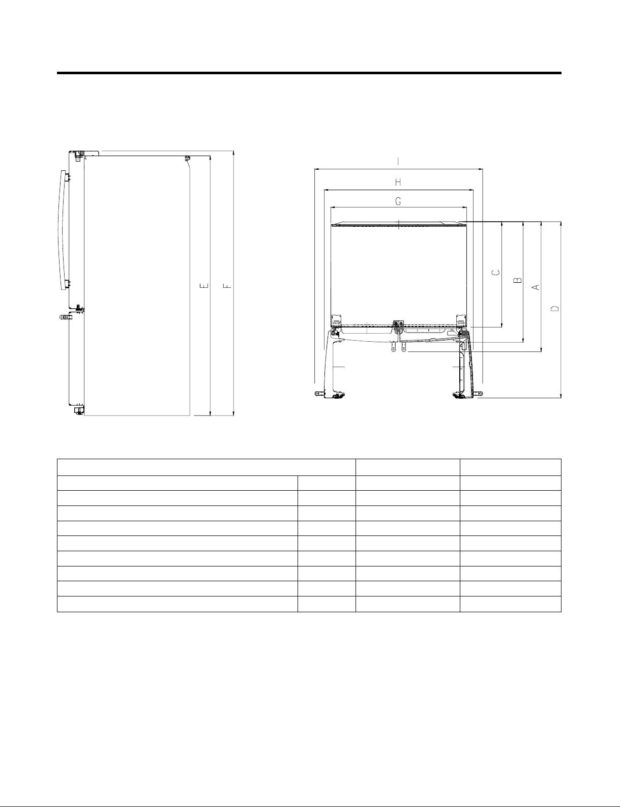
1-9 DIMENSIONS
- 4 -
Description 795.777** 795.775**
Depth w/ Handles A 30 in. 34 1/4 in.
Depth w/o Handles B 27 1/2 in. 31 3/4 in.
Depth w/o Door C 23 5/8 in. 27 7/8 in.
Depth (Total with Door Open) D 42 1/4 in. 46 1 /2 in.
Height to Top of Case E 68 3/8 in. 68 3/8 in.
Height to Top of Door Hinge F 69 3/4 in. 69 3/4 in.
Width G 35 3/4 in. 35 3/4 in.
Width (door open 90 deg. w/o handle) H 39 1/4 in. 39/1/4 in.
Width (door open 90 deg. w/ handle) I 44 1/4 in. 44 1/4 in.
- 5 -
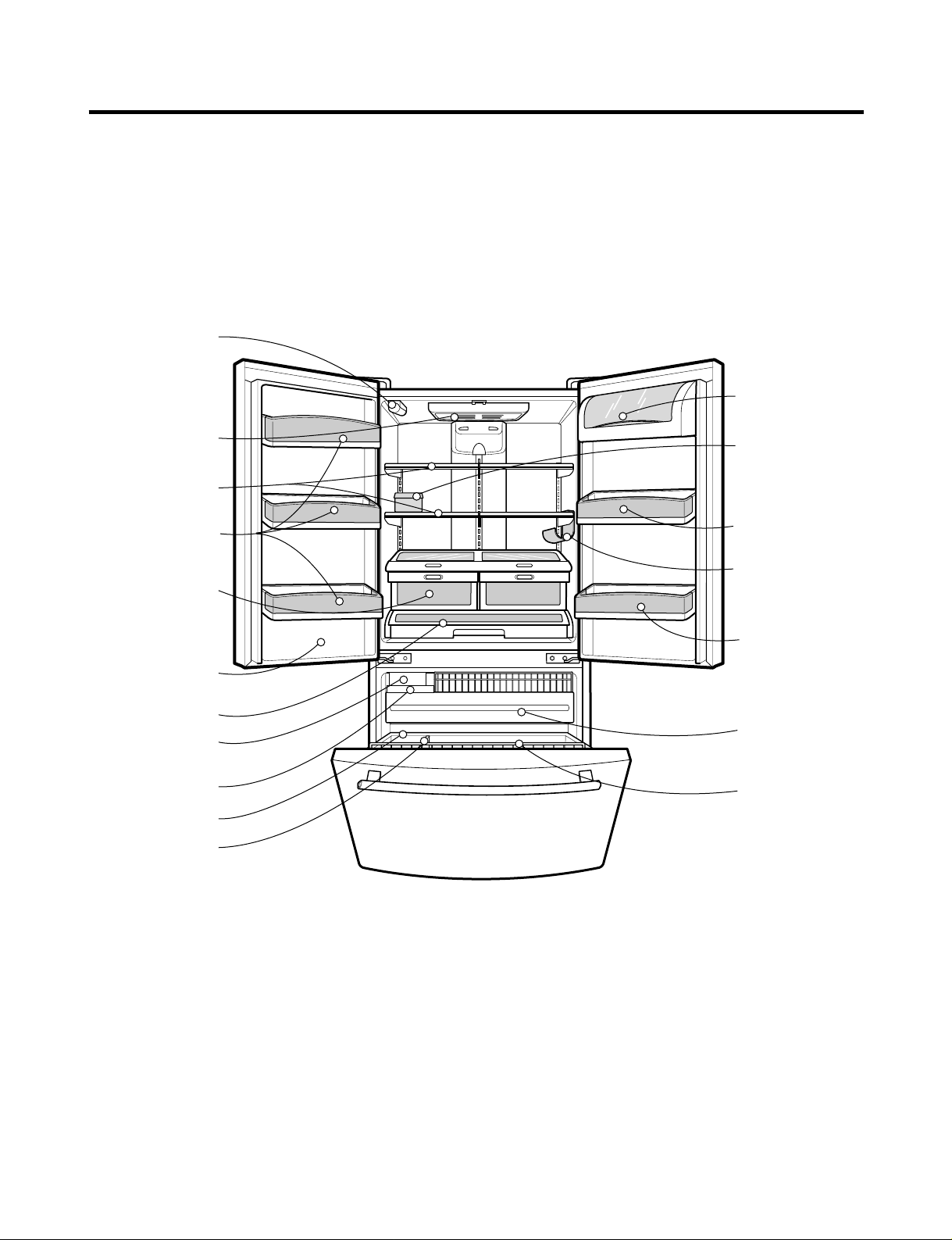
2. PARTS IDENTIFICATION
Refrigerator Light
Refrigerator
Shelves
Super Fresh
Crisper with
Tilt-Out
Compartment
Adjust Cube
Ice Maker
Glide'N'Serve
Ice Bin
Durabase
Divider
Pull out Drawer
Tilt-Out
Door Basket
(795.7754*, 7755*
Model Only)
Modular
Door Bins
Modular
Door Bins
Bottle Holder
(795.7755*,77729
Models Only)
Dairy Bin
Egg Box
Modular
Door Bins
Filter
Cover Front
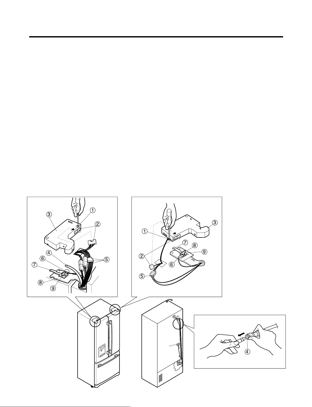
3-1 REMOVING AND REPLACING REFRIGERATOR DOORS
● Removing Refrigerator Door
ww
CAUTION: Before you begin, unplug the refrigerator. Remove food and bins from doors.
uu
Left Door
1. Disconnect water supply tube by pushing back on the disconnect ring (4).
2. Open door. Loosen top hinge cover screw (1).
Use flat tip screwdriver to pry back hooks on front underside of cover (3). Lift up cover.
3. Disconnect door switch wire harness (2). Remove cover.
4. Attach the tube on the door with door.
5. Pull out the tube.
6. Disconnect the three wire harnesses (5). Remove the grounding screw (6).
7. Rotate hinge lever (7) counterclockwise and remove. Lift top hinge (8) free of hinge lever latch (9).
ww
CAUTION: When lifting hinge free of latch, be careful that door does not fall forward.
8. Lift door up from middle hinge pin (10) and remove door.
9. Place door, inside facing up, down onto a non-scratching surface.
uu
Right Door
1. Open door. Loosen top hinge cover screw (1). Lift up cover (3).
2. Disconnect door switch wire harness (2). Remove cover.
3. Disconnect wire harness (5). Remove the grounding screw (6).
4. Rotate hinge lever (7) clockwise and remove. Lift top hinge (8) free of hinge lever latch (9).
ww
CAUTION: When lifting hinge free of latch, be careful that door does not fall forward.
5. Lift door up from middle hinge pin (10) and remove door.
6. Place door, inside facing up, down onto a non-scratching surface.
- 6 -
3. DISASSEMBLY
4
3
1
4
6
2
7
8
9
5
1
7
8
3
2
6
5
9
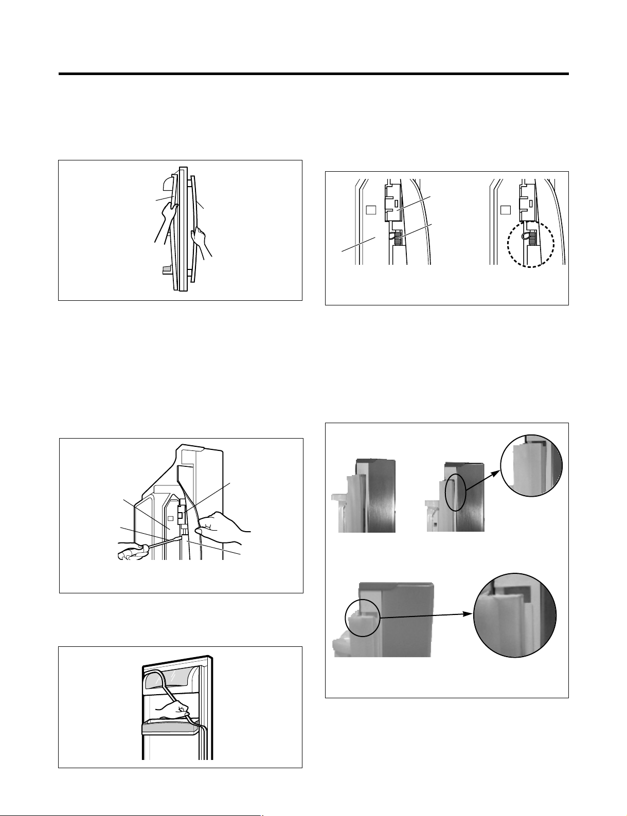
3-2 DOOR
● Door Gasket Removal
1. Remove door frame cover
Starting at top of cover and working down, snap cover
out and away from door.
2. Remove gasket bracket clips
There are two clips on each door. Start bracket removal
near one of the middle clips.
1) Pull gasket back to expose gasket bracket clip and
door frame.
2) Insert a flat tip screwdriver into seam between gasket
bracket and door frame and pry back until clips snaps
out.
3) Continue prying back along seam until all clips snap
out.
3. Remove gasket
Pull gasket free from gasket channel on the three
remaining sides of door.
● Door Gasket Replacement
1. Insert gasket bracket clips
1) Insert gasket bracket edge beneath door frame edge.
2) Turn upper gasket bracket spring so that the spring
ends are in the door channel.
3) Push in clip until you hear it snap securely into place.
4) Push in remaining two clips until you hear each snap
securely into place.
Note: Make sure that no part of gasket bracket edge
protrudes from beneath door frame edge.
2. Insert gasket into channel
1) Snap gasket assembly into the door bracket.
<Inserting the Gasket Assembly into the Bracket Door>
- 7 -
Frame Cover
Handle
Door
Frame
Gasket
Bracket Clip
Flat Tip
Screwdriver
Gasket
Bracket
Figure 1
Figure 2
Figure 3
Door
Frame
Gasket
Bracket Clip
Spring
IncorrectCorrect
Figure 4
Figure 5
Correct
Incorrect
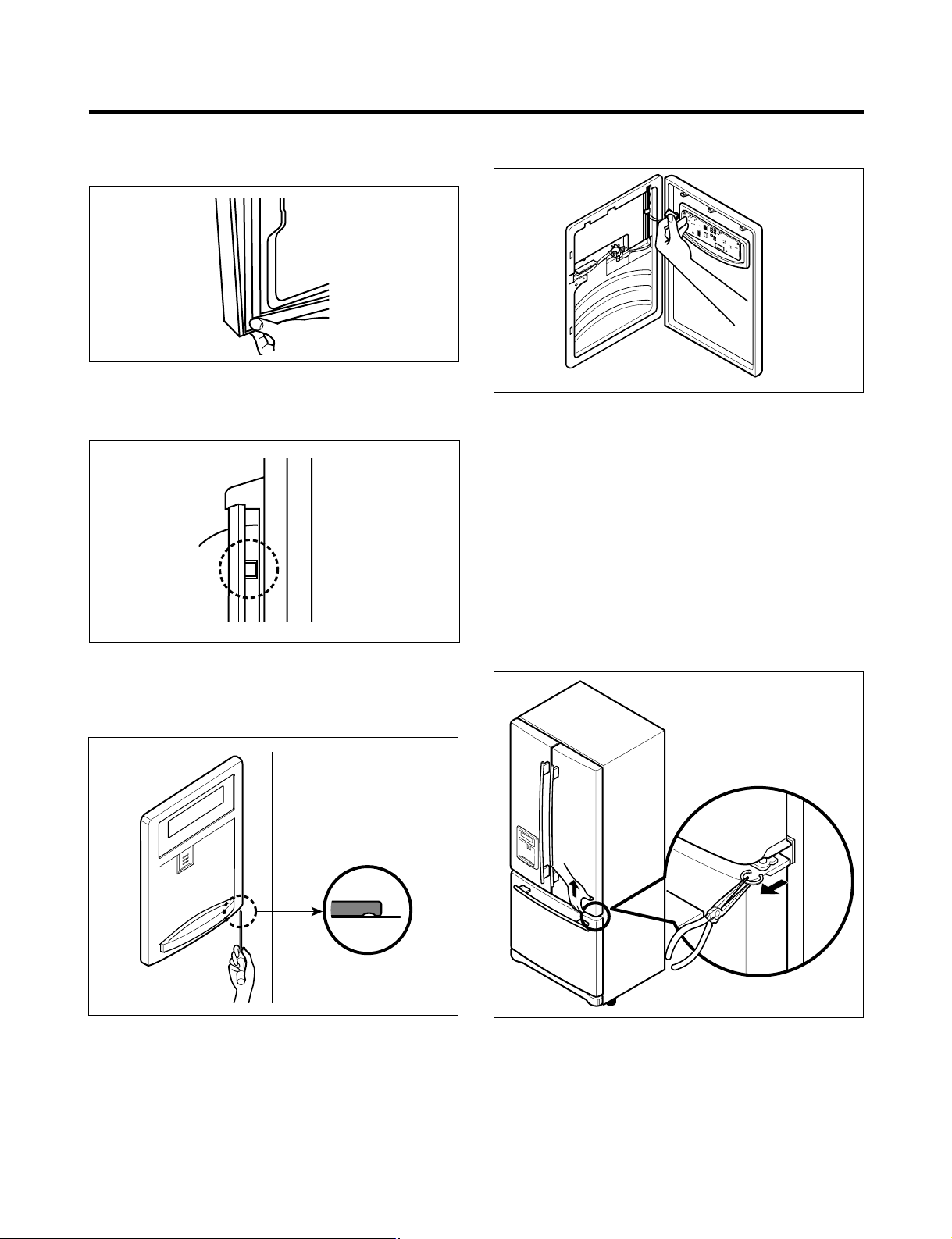
2) Press gasket into channels on the three remaining
sides of door.
3. Replace door frame cover
Starting at top of cover and working down, snap cover
back into door.
3-3 TO REMOVE THE DISPENSER
1. Use fiat tip screwdriver to pry back hooks on botton
underside of cover dispenser.
2. Pry off cover dispenser.
Disconnect wire harness.
3. Replace cover dispenser in opposite manner and order
of removal.
3-4 DOOR ALIGNMENT
If the space between your doors is uneven, follow the
instructions below to align the doors:
1. With one hand, lift up the door you want to raise at
middle hinge.
2. With other hand, use pliers to insert snap ring as shown.
3. Insert additional snap rings until the doors are aligned.
(Three snap rings are provided with unit.)
- 8 -
Figure 6
Figure 8
Figure 9
Figure 7
Figure 10
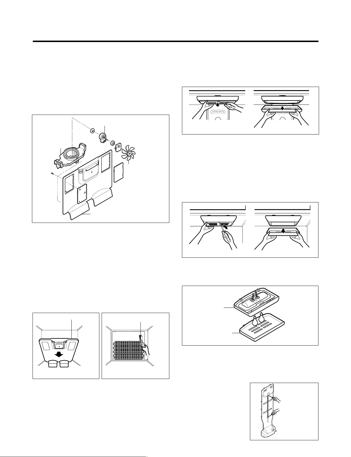
3-5 FAN AND FAN MOTOR
1. Remove the freezer shelf. (If your refrigerator has an
icemaker, remove the icemaker first)
2. Remove the plastic guide for slides on left side by
unscrewing phillips head screws.
3. Remove the grille by pulling it out and by loosening a screw.
4. Remove the Fan Motor assembly by loosening 2 screws
and disassemble the shroud.
5. Pull out the fan and separate the Fan Motor and Bracket.
3-6 DEFROST CONTROL ASSEMBLY
Defrost Control assembly consists of Defrost Sensor and
FUSE–M.
The Defrost Sensor works to defrost automatically . It is
attached to the metal side of the Evaporator and senses its
temperature. At 161.6°F(72°C), it turns the Defrost Heater off.
Fuse-M is a safety device for preventing over-heating of
the Heater when defrosting.
1. Pull out the grille assembly. (Figure 12)
2. Separate the connector with the Defrost Control
assembly and replace the Defrost Control assembly
after cutting the Tie Wrap. (Figure 13)
3-7 LAMP
3-7-1 Refrigerator Compartment Lamp
1. Unplug Refrigerator, or disconnect power at the circuit
breaker.
2. If necessary, remove top shelf or shelves.
3. Using a flat instrument, gently pry the cover loose in the
front as shown. Rotate downward to remove rear tabs.
4. Make sure the bulbs are cool to the touch.
Turn bulbs counterclockwise to remove.
5. Assemble in reverse order by snapping the Lamp Cover
in, engaging the rear tabs followed by the front tabs.
(Max. 60 W-2EA)
3-7-2 Freezer Compartment Lamp
1. Unplug refrigerator power cord form outlet.
2. Using a flat instrument, gently pry the lamp cover loose
in the front as shown. Rotate downward to remove the
rear tabs.
3. Make sure the bulb is cool to the touch. Turn the bulb
counterclockwise to remove.
4. Replace with a new 60-watt appliance bulb.
5. Insert tabs on back of cover into slots in freezer ceiling.
Push cover up to snap front into place.
3-8 CONTROL BOX-REFRIGERATOR
1. First, remove all shelves in the refrigerator, than remove
the Refrigerator control Box by loosening 2 screws.
2. Remove the Refrigerator Control Box by pulling it
downward.
3. Disconnect the lead wire on the right position and
separate the lamp sockets.
3-9 MULTI DUCT
1. Remove an upper and
lower Cap by using a flat
screwdriver, and loosen 2
screws. (Figure 17)
2. Disconnect the lead wire
on the bottom position.
- 9 -
BRACKET
MOTOR
GRILLE
FAN MOTOR
FAN
Figure 11
GRILLE ASSEMBLY
Figure 12
DEFROST-CONTROL
ASSEMBLY
Figure 13
Figure 14
Figure 15
CONTROL BOX
COVER LAMP
Figure 16
Figure 17
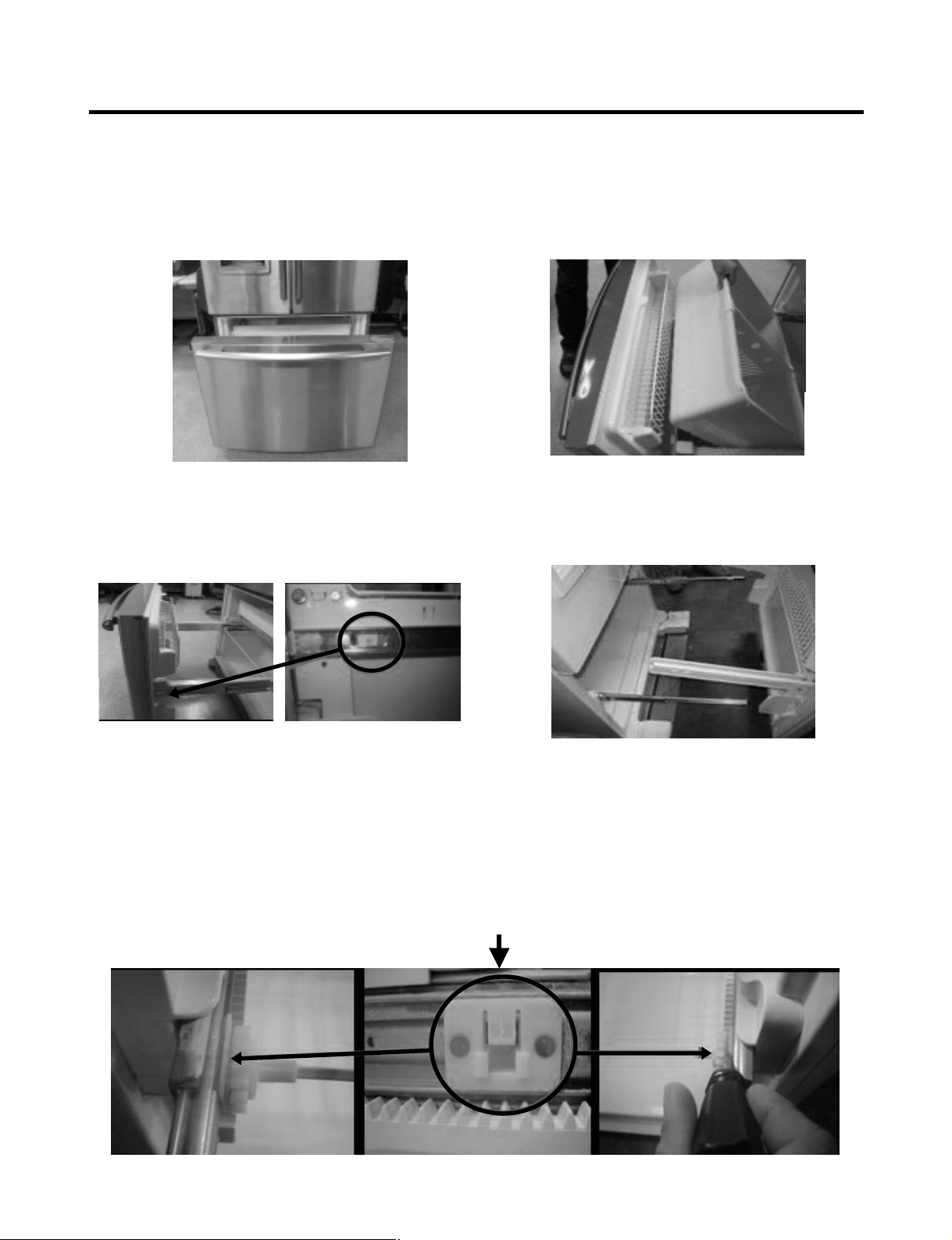
3-10 HOW TO REMOVE AND REINSTALL THE PULLOUT DRAWER
3-10-1 FOLLOW STEPS TO REMOVE
- 10 -
Step 1) Open the freezer door.
Step 3) Remove the two screws from the guide rails (one
from each side).
Step 2) Remove the lower basket.
Step 4) Lift the freezer door up to unhook it from the rail
support and remove.
Pull both rails to full extension.
Step 5) First: Remove the gear from the left side first by releasing the tab behind the gear, place a screwdriver between the
gear and the tab and pull up on the gear.
Second: Remove the center rail.
Third: Remove the gear from the right side by following the same steps for the left side.
NOTE: THIS TAB MUST BE PUSHED IN TO RELEASE THE GEAR.
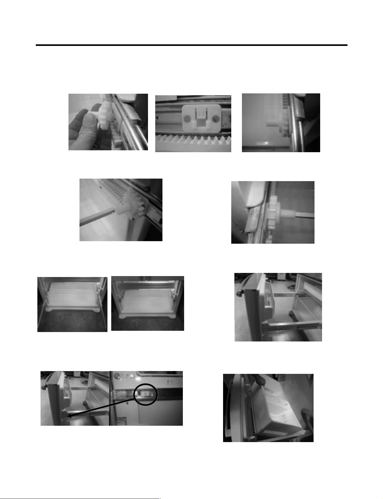
3-10-2 FOLLOW STEPS TO REINSTALL
Step 1) Reinstall the right side gear into the clip.
Step 2) Insert the rail into the right side gear. Gears do not
need to be perpendicular to each other.
Step 4) The rail system will align itself by pushing the rails
all the way into the freezer section.
Pull the rails back out to full extension.
Step 6) Reinstall the two screws into the guide rails
(one from each side).
Step 3) Insert the rail into the left side gear, and insert the
gear into the clip.
Step 5) Reinstall the freezer door by inserting the rail tabs
into the guide rail.
Step 7) Reinstall the lower basket, and close the freezer
door.
- 11 -
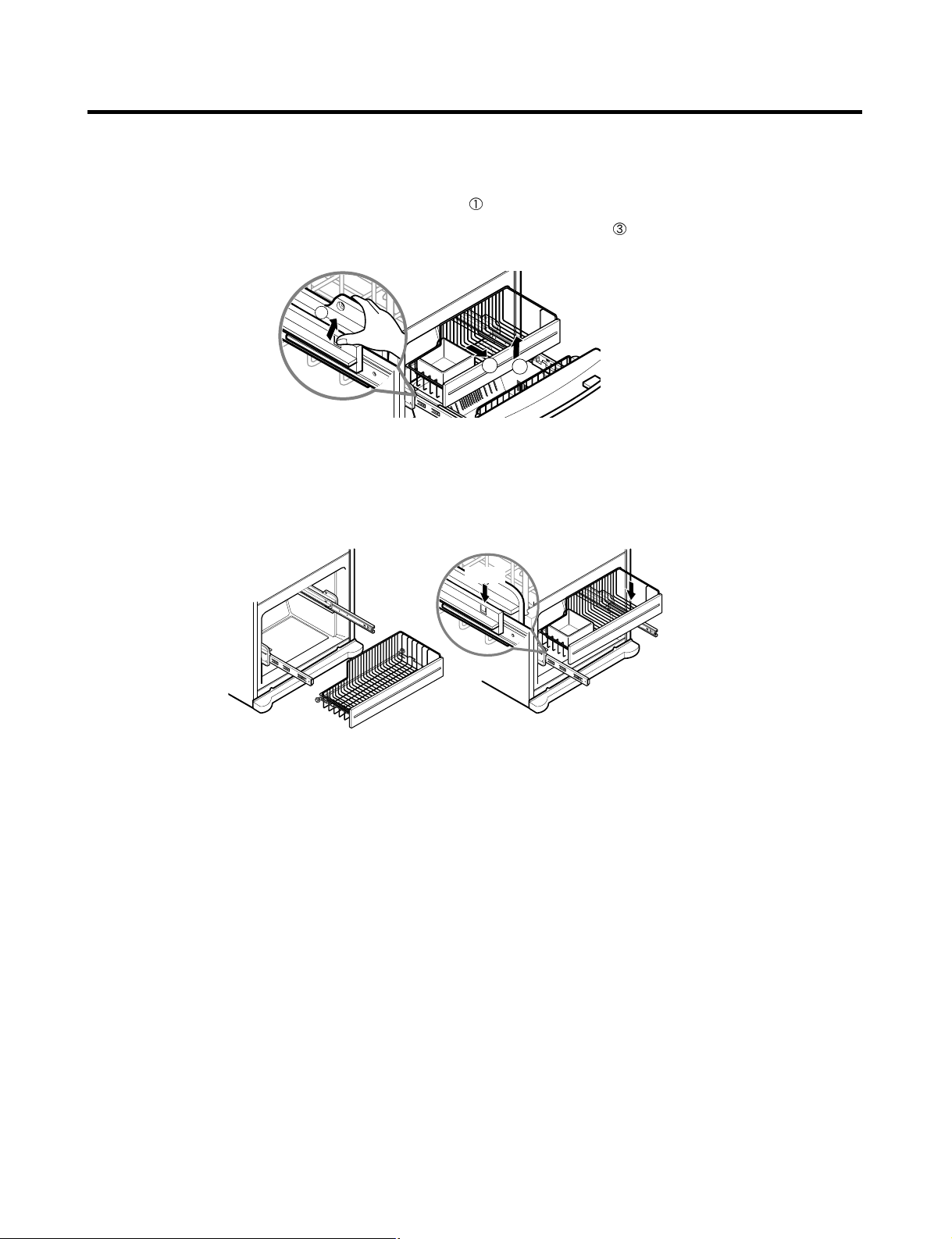
3-10-3 PULL OUT DRAWER
To separate the drawer, push the front left and right hooks in
direction to pull up and remove.
Then gently lift the gear part of rear left and right side of the drawer and pull it out in
direction.
To install, reposition the gear part of rear left and right side of the drawer after pulling out both rails as much as possible,
and gently push down both left and right side while checking the hook on the front part.
- 12 -
1
3
2
Hook
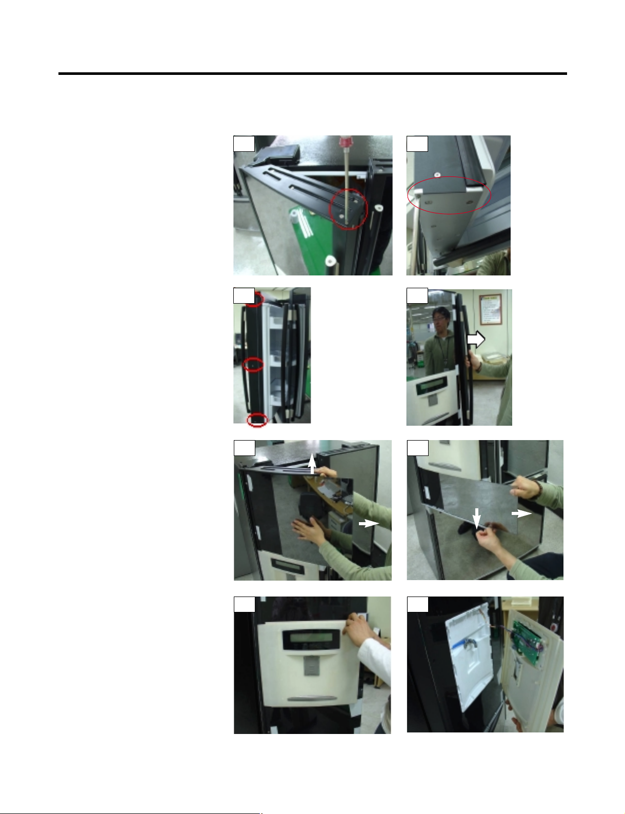
3-11 TRIM KIT ASSEMBLY AND AISASSEMBLY METHOD (795.77719,77729 MODELS ONLY)
3-11-1 ASSEMBLY AND DISASSEMBLY METHOD OF LEFT DOOR GLASS AND DISPLAY OF THE REFRIGERATOR
1. Remove the 2 screws on the top
refrigerator door trim, circled in Photo
# 1.
2. Remove the 2 screws on the bottom
refrigerator door trim, circled in photo
# 2.
3. While holding the door handle (to
prevent it from falling) remove the 3
screws on the side trim that holds the
handle on.(see photo # 3)
4. Remove the door handle. (see photo
# 4)
5. While lifting up on the top door trim,
slide the glass front (above the
dispenser) to the right to remove it.
(see photo # 5)
6. While pulling down on the bottom door
trim, slide the glass front (below the
dispenser) to the right to remove it.
(see photo # 6)
7. Once the glass is removed, the
dispenser cover can be removed by
pulling it out by the right side and gently
pulling out of the left door trim slot. (see
photos 7 & 8)
8. The right side door glass is removed
in the same manner as the left.
However because it will not have the
dispenser the glass will be one
piece.
9. Reassemble in reverse order.
- 13 -
1
3
5
7 8
6
4
2
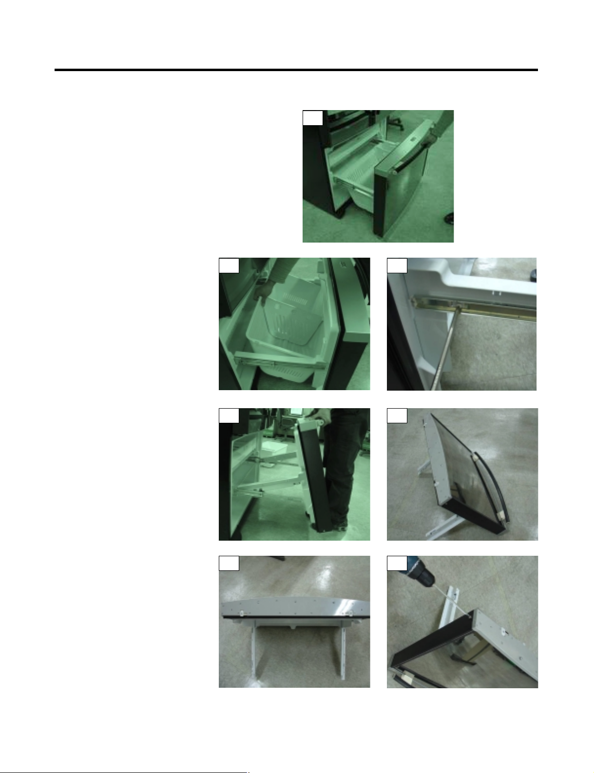
3-11-2 ASSEMBLY AND DISASSEMBLY METHOD OF FREEZER DOOR AND GLASS
1. Fully open the freezer drawer
as shown in photo # 1.
2. Lift out the freezer basket as
shown in photo # 2.
3. Remove the 2 screws
(one on each side shown in photo # 3.
4. Hold the freezer handle and pull
up to remove the door assembly,
as shown in photo # 4.
5. Put the freezer door facing down
(on a clean soft surface to prevent
scratching the top trim) as shown in
photo # 5.
6. Remove all the screws hold the bottom
door trim in place. (be careful not to
remove the 2 screws circled in
photo # 6).
7. Remove the screw at the bottom of
each side trim shown in photo # 7.
(continued on the next page)
- 14 -
1
2 3
4 5
6 7
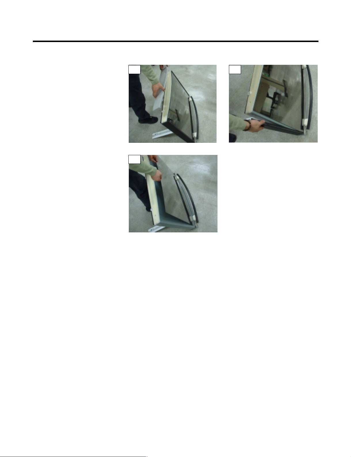
3-11-2 ASSEMBLY AND DISASSEMBLY METHOD OF FREEZER DOOR AND GLASS
8. Pull off the bottom cover as shown in
photo # 8.
9. Remove one of the side trim pieces by
pulling it out slightly the up to remove
it from the top door trim. As shown in
photo # 9.
10. Carefully pull out the freezer door
glass as shown in photo # 10.
11. Reassemble in reverse order.
- 15 -
8
10
9
4-1 COMPRESSOR
4-1-1 Role
The compressor intakes low temperature and low pressure
gas from the evaporator of the refrigerator and compresses
this gas to high-temperature and high-pressure gas. It then
delivers the gas to the condenser.
4-1-2 Composition
The compressor includes overload protection. The PTC
starter and OLP (overload protector) are attached to the
outside of the compressor. Since the compressor is
manufactured to tolerances of 1 micron and is hermetically
sealed in a dust and moisture-free environment, use
extreme caution when performing repairs.
4-1-3 Note for Usage
(1) Be careful not to allow over-voltage and over-current.
(2) If compressor is dropped or handled carelessly, poor
operation and noise may result.
(3) Use proper electric components appropriate to the
Particular Compressor in your product.
(4) Keep Compressor dry.
If the Compressor gets wet (in the rain or a damp
environment) and rust forms in the pin of the Hermetic
Terminal, poor operation and contact may result.
(5) When replacing the Compressor, be careful that dust,
humidity, and soldering flux don’t contaminate the inside
of the compressor. Dust, humidity, and solder flux
contaminate the cylinder and may cause noise,
improper operation or even cause it to lock up.
4-2 PTC-STARTER
4-2-1 Composition of PTC-Starter
(1) PTC (Positive Temperature Coefficient) is a no-contact
semiconductor starting device which uses ceramic
material consisting of BaTiO
3.
(2) The higher the temperature is, the higher the resistance
value. These features are used as a starting device for
the Motor.
4-2-2 Role of PTC-Starter
(1) The PTC is attached to the Sealed Compressor and is
used for starting the Compressor Motor.
(2) The compressor is a single-phase induction motor.
The starting operation, the PTC allows current flow to
both the start winding and main winding.
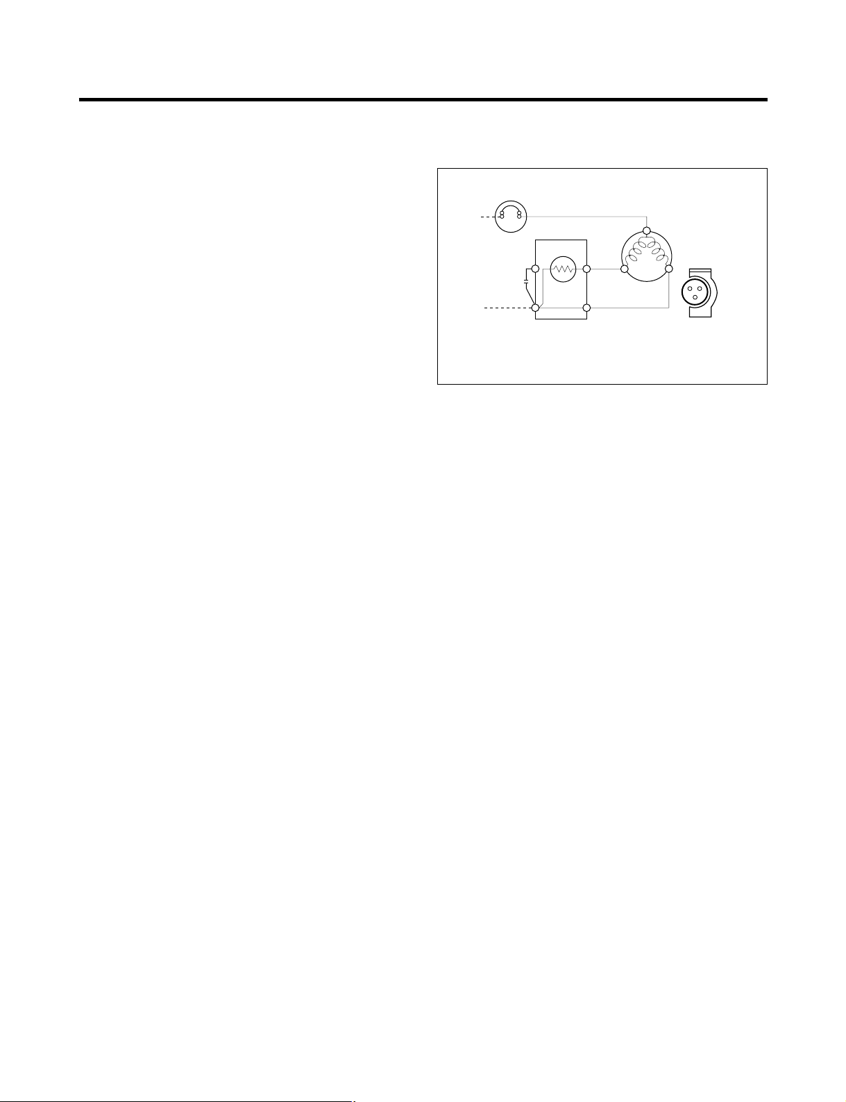
4-2-3 PTC-Applied Circuit Diagram
● Starting Method for the Motor
4-2-4 Motor Restarting and PTC Cooling
(1) It requires approximately 5 minutes for the pressure to
equalize before the compressor can restart.
(2) The PTC device generates heat during operation.
Therefore, it must be allowed to cool before the
compressor can restart.
4-2-5 Relation of PTC-Starter and OLP
(1) If the compressor attempts to restart before the PTC
device is cooled, the PTC device will allow current to
flow only to the main winding.
(2) The OLP will open because of the over current
condition. This same process will continue (3 to 5
times) when the compressor attempts to restart until
the PTC device has cooled. The correct OLP must be
properly attached to prevent damage to the
compressor.
Parts may appear physically identical but could have
different electrical ratings. Replace parts by part
number and model number. Use only approved
substitute parts.
4-2-6 Note for Using the PTC-Starter
(1) Be careful not to allow over-voltage and over-current.
(2) Do not drop or handle carelessly.
(3) Keep away from any liquid.
If liquid such as oil or water enters the PTC,
PTC materials may fail due to breakdown of their
insulating capabilities.
(4) If the exterior of the PTC is damaged, the resistance
value may be altered. This can cause damage to the
compressor and result in a no-start or hard-to-start
condition.
(5) Always use the PTC designed for the compressor and
make sure it is properly attached to the compressor.
Parts may appear physically identical but could have
different electrical ratings. Replace parts by part
number and model number. Use only approved
substitute parts.
4. ADJUSTMENT
- 16 -
PTC STARTER
SEALED
TERMINAL
COMPRESSOR
MOTOR
C
M
S
M
3
6
5
2
S
N
L1
OVERLOAD PROTECTOR
Resistance Starter Capacitor Running
PTC
Figure 18
 Loading...