


795.78306.801
Table of contents
 Loading...
Kenmore 795.78306.801, 795.78314.800, 795.78316.802, 795.78309.802, 795.78319.800 User Manual
...
Sears, Roebuck and Co., Hoffman Estates, IL60179 U.S.A.
www.sears.com
BOTTOM FREEZER REFRIGERATOR
ENGLISH
R
REFRIGERATOR
SERVICE MANUAL
CAUTION
BEFORE SERVICING THE PRODUCT
READ THE SAFETY PRECAUTIONS IN THIS MANUAL
Models:
795.78302.800/801/802
795.78304.800/801/802
795.78306.800/801/802
795.78309.800/801/802
795.78312.800/801/802
795.78314.800/801/802
795.78316.800/801/802
795.78319.800/801/802

CONTENTS
-2-
SAFETY PRECAUTIONS
Please read the following instructions before servicing your
refrigerator.
1. Check the refrigerator for current leakage.
2. To prevent electric shock, unplug before servicing.
3. Always check line voltage and amperage.
4. Use standard electrical components.
5. Don’r touch metal products in the freezer with wet hands.
This may cause frost bite.
6. Prevent water from spiling on to electrical components or
the machine parts.
7. Before tilting the refrigerator, remove all materials from on
or in the refrigerator.
8. When servicing the evaporator, wear gloves to prevent
injuries from the sharp evaporator fins.
9. Service on the refrigerator should be performed by a
qualified technician. Sealed system repair must be performed
by a CFC certified technician.
SAFETY PRECAUTIONS .....................................................................................................
1. SPECIFICATIONS ............................................................................................................
2. PARTS IDENTIFICATION .................................................................................................
3. DISASSEMBLY .................................................................................................................
3.1 Door .............................................................................................................................
3.2 Door alignment .............................................................................................................
3.3 Fan and fan motor .......................................................................................................
3.4 Defrost control assembly .............................................................................................
3.5 Lamp ............................................................................................................................
3.6 Control box-refrigerator ................................................................................................
3.7 Multi duct ......................................................................................................................
3.8 How to remove and reinstall the pull out drawer ..........................................................
3.9 Cover Valve ..................................................................................................................
4. COMPRESSOR ELECTRICAL ........................................................................................
4.1 Compressor ..................................................................................................................
4.2 PTC-Starter/Combo .....................................................................................................
4.3 OLP (Overload Protector) ............................................................................................
4.4 To remove the cover PTC ............................................................................................
4.5 To remove the Combo ..................................................................................................
5. CIRCUIT DIAGRAM .........................................................................................................
6. TROUBLESHOOTING ......................................................................................................
6.1 Compressor and electrical components ......................................................................
6.2 PTC/Combo and OLP ................................................................................................
6.3 Other electrical components .......................................................................................
6.4 Service diagnosis chart ...............................................................................................
6.5 Refrigeration cycle ......................................................................................................
7. OPERATION PRINCIPLE AND REPAIR METHOD OF ICEMAKER ...............................
7.1 Operation principle ......................................................................................................
7.2 Ice maker functions .....................................................................................................
7.3 Defect diagnosis function ............................................................................................
8. DESCRIPTION OF FUNCTION & CIRCUIT OF MICOM .................................................
8.1 Function .....................................................................................................................
8.2 PCB function ...............................................................................................................
8.3 Resistance specification of sensor ..............................................................................
8.4 Troubleshooting ...........................................................................................................
8.5 Main PWB assembly and parts list ..............................................................................
8.6 PWB diagram ..............................................................................................................
9. EXPLODED VIEW AND REPLACEMENT PART LIST ....................................................
783**.800 ..........................................................................................................................
783**.801 ..........................................................................................................................
783**.802 ..........................................................................................................................
2
3
5
6
6
7
8
8
8
8
8
9
12
13
13
13
14
14
14
15
16
16
17
18
19
20
22
22
23
24
25
25
30
31
32
34
35
37
42
50
58

All parts of this appliance capable of conducting electrical current are grounded. If grounding wires, screws, straps, clips, nuts or washers
used to complete a path to ground are removed for service, they must be returned to their original position and properly fastened.
This information is intended for use by individuals possessing adequate background of electrical, electronic and mechanical experience.
Any attempt to repair a major appliance may result in personal injury and property damage. The manufacturer or seller cannot be
responsible for the interpretation of this information, nor can it assume any liability in connection with its use.
Minimum Compressor Capacity Vacuum ...................................21 in
Minimum Equalized Pressure
@70°F......................................................................49PSIG
@90°F......................................................................56PSIG
Refrigerant R134a................................................................. 4.2. oz
Compressor ................................................................... 700 BTU/hr
Clearance must be provided at top, sides and rear of the refrigerator
for air circulation.
AT TOP..........................................................................................1 in
AT SIDES.................................................................................. 1/8 in
AT REAR.......................................................................................1 in
ELECTRIC AL SP E CIFIC ATION S
................................................................................................................... -6°F
to
+8
°
F
Defrost Control ...................................................................................................................................................................................Automatic
Defrost Thermostat .....................................................................................................................................................................................50°F
Electrical Rating : 115VAC, 60Hz...............................................................................................................................................................1- 5 A
Maximum Current Leakage .....................................................................................................................................................................0.5mA
Maximum Ground Path Resistance ..................................................................................................................................................0.14 Ohms
Energy Consumption
....................................................................................................................................22 cu.ft. 466 kWh/yr (Energy Star)
Control Po sitio n : MID/M ID
And Ambient of: 70°F
Fresh Food, °F...............................................................
33°F
to
41°F
Frozen Food, °F..............................................................
Percent Running Time........................................................
90°F
......................................................................................
......................................................................................
......................................................................................
.
-4°F to +4°F
25%-35%
45%-60%
33°F to 41°F
-4°F to +4°F
...
.
1-1 DISCONNECT POWER CORD BEFORE SERVICING IMPORTANT:
RECONNECT ALL GROUNDING DEVICES.
1-2 IMPORTANT NOTICE
1.3
1-4 NO LOAD PERFORMANCE
1-5 REFRIGERATION SYSTEM
1-6 INSTALLATION
1. SPECIFICATIONS
- 3 -
Freezer Temperature Control (Middle setting)

EVAPORATOR
EVAPORATOR FAN
DRYER
HOT LOOP
COMPRESSOR
CONDENSER
CONDENSER FAN
FRESH FOOD
FREEZER
Vegetable box
COLD AIR
MIXED AIR
AIR RETURN TO
EVAPORATOR
EVAPORATOR
PERFORMANCE DATA
(NORMAL OPERATING CONDITIONS)
SYSTEM PRESSURE (PSIG)
HIGH SIDE LOW SIDE
AMB WATTS
(-4) to 1
(-5) to (-2)
(-2) to 3
132 (+3 / -3)
98 (+5 / -3)
180 (+5 / -5)
98 (+10 / -10)
98 (+10 / -10)
103 (+5 / -5)
90°F
70°F
110°F
1-7 REPLACEMENT PARTS
1-8 AIR FLOW / CIRCULATION D’AIR.
- 4 -
Compressor (SVC kit) .......ACF67062301
Relay .................................6748JJ8005B
Overload ...........................6750JJ8004B
Defrost Thermostat ...........6615JB2005C
Defrost Heater ...................5300JB1100J
Evaporator Fan Motor .......4681JK1004A
Capacitor..........................0CZZJB2012J
Compressor (Hi-Side) ........2521JJ8008B
Evaporator (Lo-Side) .........5421JJ1001B
Condenser ........................5403JJ1007A
Dryer .................................5851JJ2002F
Condenser Fan Motor ........4681JB1029J
Temperature Control .........6871JB2046B
Main Control .....................EBR41531305

2. PARTS IDENTIFICATION
- 5 -
Ice Bin
Durabase
Divider
Modular Door Bins
Can Rack*
*On some models
Egg Box
Glide-Out Drawer Basket
Freezer Light
Dairy Corner
B
C
D
A
F
E
Use this section to become more familiar with the parts and features.
NOTE:This guide covers several different models.The refrigerator you have purchased may have some
or all of the items listed below.The locations of the features shown below may not match your model.
G
H
I
J
L
M
K
N
O
Cool Sense Electronic Temperature
Control System
Snack Pan
Refrigerator Light
Refrigerator Shelves
Supra Fresh Crisper with Tilt-Out Compartment
Adjusta Cube Ice Maker
A
B
C
D
F
G
H
K
O
N
M
L
E
I
K
J
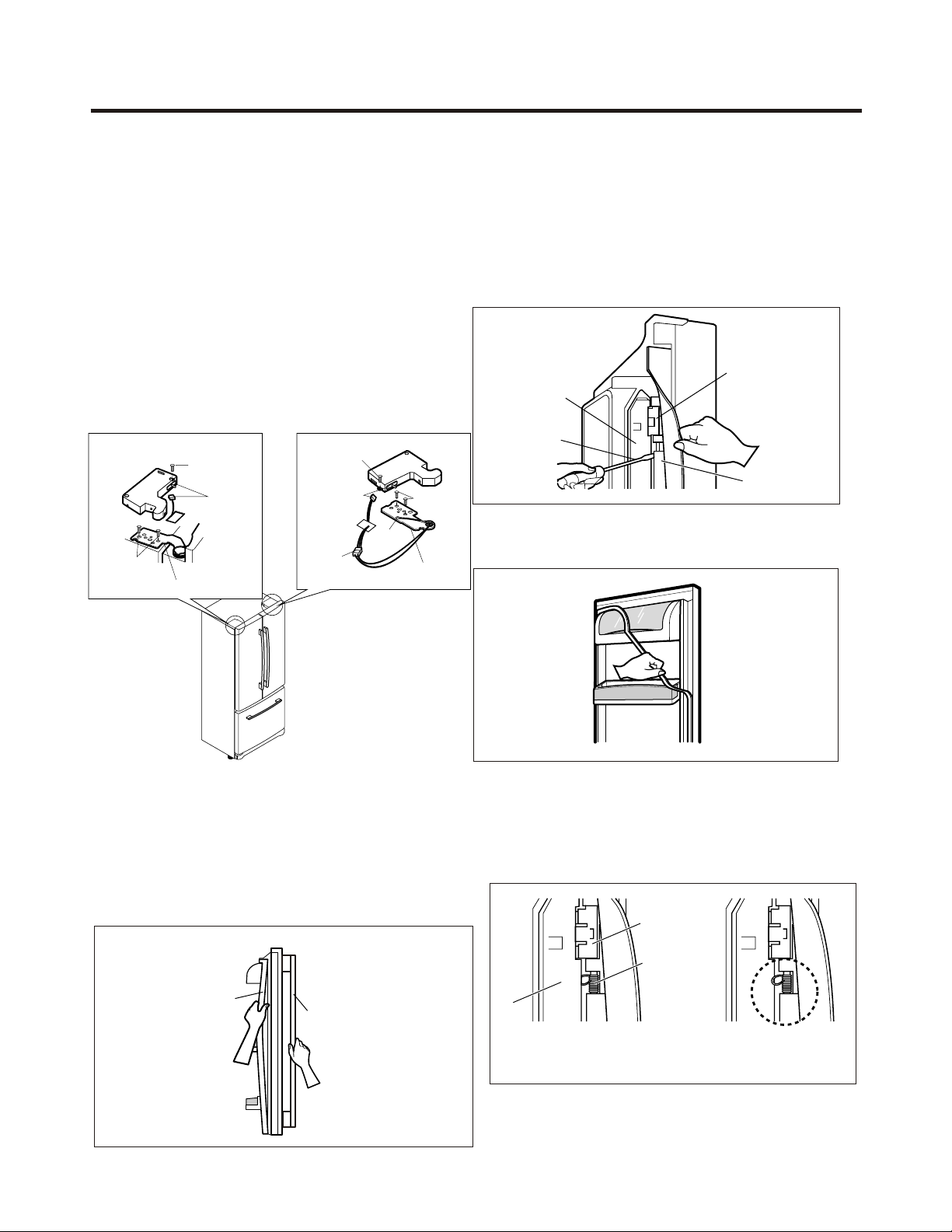
3-1 DOOR
2. Remove gasket bracket clips
There are two clips on each door. Start bracket removal
near one of the middle clips.
1) Pull gasket back to expose gasket bracket clip and
door frame.
2) Insert a flat tip screwdriver into seam between gasket
bracket and door frame and pry back until clips snap
out.
3) Continue prying back along seam until all clips snap
out.
3. Remove gasket
Pull gasket free from gasket channel on the three
remaining sides of door.
Door Gasket Replacement
1. Insert gasket bracket clips
1) Insert gasket bracket edge beneath door frame edge.
2) Turn upper gasket bracket spring so that both spring
ends are in the door channel.
3) Push in clip until you hear it snap securely into place.
4) Push in remaining two clips until you hear each snap
securely into place.
Note: Make sure that no part of gasket bracket edge
Protrudes from beneath door frame edge.
3. DISASSEMBLY
- 6 -
Frame Cover
Handle
Gasket
Door
Bracket Clip
Frame
Flat Tip
Screwdriver
Gasket
Bracket
Figure 3
Figure 2
Figure 1
Figure 4
Gasket
Bracket Clip
Spring
Door
Frame
Correct Incorrect
Figure 5
Door Gasket Removal
1. Remove door frame cover
Starting at top of cover and working down, snap cover
out and away from door.
(3)
(1)
(4)
(1)
(2)
(3)
(4)
(5)
(5)
(2)
(6)
? Left Door
• Loosen the cover screw (1).
• Disconnect door switch wire (2).
• Loosen hinge bolts (3).
• Lift off the top hinge (4).
• Place the door on a non-scratching
surface with the inside up.
? Right Door
• Loosen the cover screw (1).
• Disconnect door switch wire (2).
• Disconnect wire harness (5).
• Loosen hinge bolts (3).
• Loosen ground screw (6).
• Lift off the top hinge (4).
• Place the door on a non-scratching
surface with the inside up.
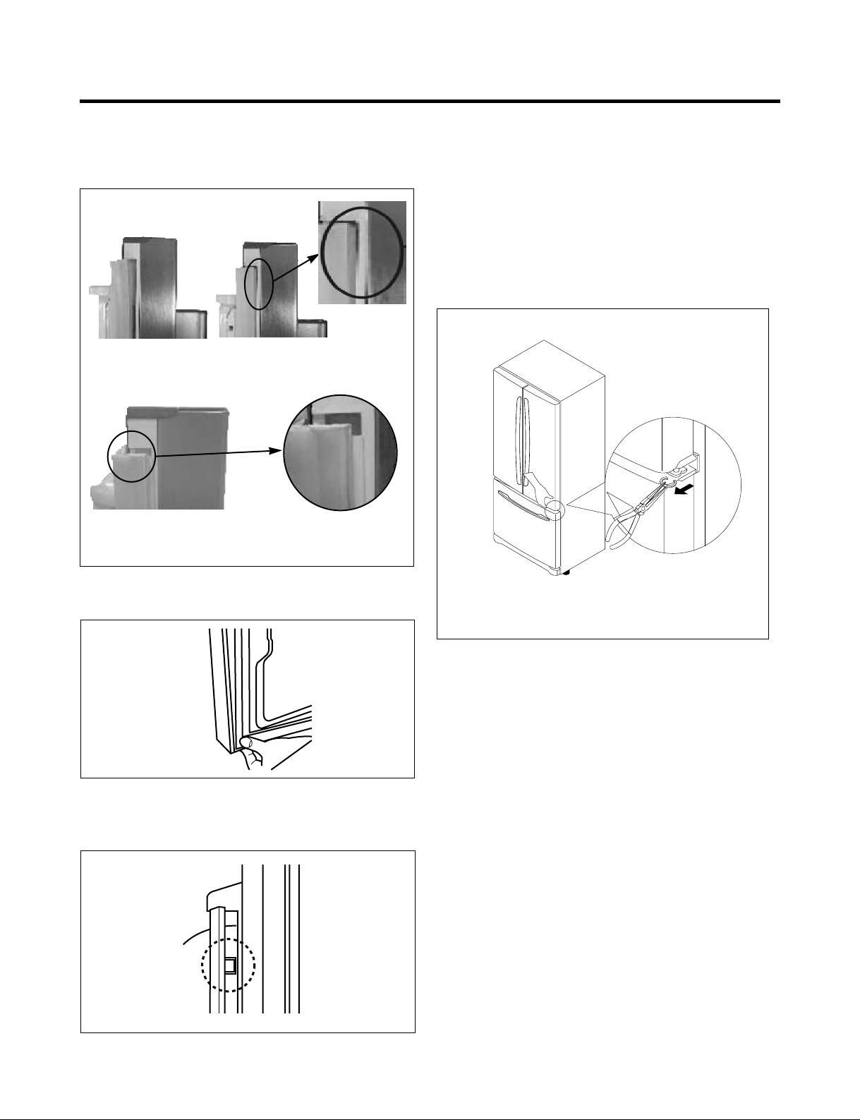
2. Insert gasket into channel
1) Snap gasket assembly into the door bracket.
Inserting the Gasket Assembly into the Bracket Door.
2) Press gasket into channel on the three remaining
sides of door.
3. Replace door frame cover
Starting at top of cover and working down, snap the cover
back into door.
3-2 DOOR ALIGNMENT
If the space between your doors is uneven, follow the
instructions below to align the doors:
1. With one hand, lift up the door you want to raise near
the middle hinge.
2. With other hand, use pliers to insert snap ring at the
3. Insert additional snap rings until the doors are aligned.
(Three snap rings are provided with the product.)
- 7 -
Figure 6
Correct
Incorrect
Figure 7
Figure 8
Figure 9
middle hinge as shown.
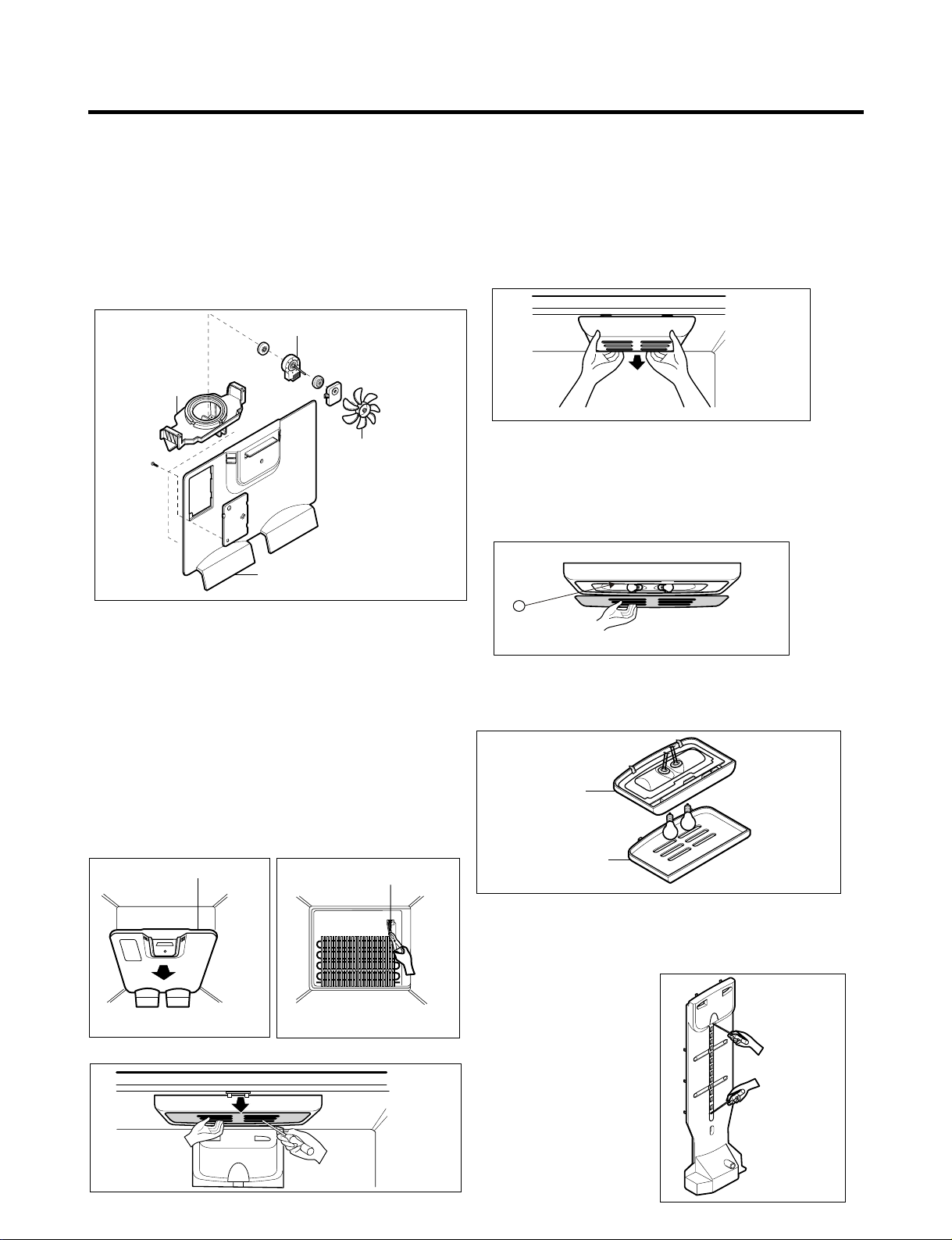
3-3 FAN AND FAN MOTOR
1. Remove the freezer shelf. (If your refrigerator has an
icemaker, remove the icemaker first)
2. Remove the plastic guide for slides on left side by
unscrewing phillips head screws.
3. Remove the grille by removing one screw and pulling the
grille forward.
4. Remove the Fan Motor assembly by loosening 2 screws.
5. Pull out the fan and separate the Fan Motor and Bracket.
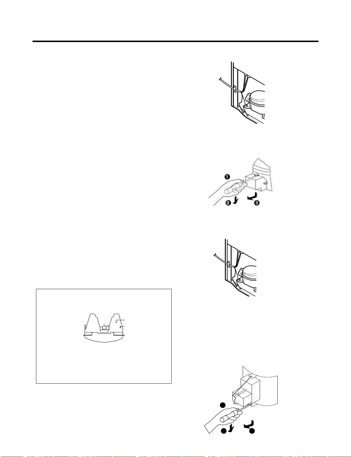
3-4 DEFROST CONTROL ASSEMBLY
Defrost Control assembly consists of Defrost Sensor and
FUSE–M.
The Defrost Sensor works to defrost automatically. It is
attached to the metal side of the Evaporator and senses its
Temperature.
Fuse-M is a safety device for preventing over-heating of
the evaporator area when defrosting.
1. Pull out the grille assembly. (Figure 12)
2. Separate the connector with the Defrost Control
assembly and replace the Defrost Control assembly
after cutting the tie wrap. (Figure 13)
3-5 LAMP
3-5-1 Refrigerator Compartment Lamp
3-5-2 Freezer Compartment Lamp
3-6 REFRIGERATOR CONTROL BOX
1. First, remove all shelves in the refrigerator, than remove
the Refrigerator control Box by loosening 2 screws.
2. Remove the Refrigerator Control Box by pulling it
downward.
3. Disconnect the lead wire on the right position and
separate the lamp sockets.
3-7 MULTI DUCT
1. Remove the upper and
lower caps by using a flat
screwdriver, and remove 2
screws. (Figure 17)
2. Disconnect the lead wire
on the bottom position.
- 8 -
GRILLE ASSEMBLY
Figure 12
DEFROST-CONTROL
ASSEMBLY
Figure 13
Figure 14
Figure 15
CONTROL BOX
COVER LAMP
Figure 17
Figure 18
GRILLE
FAN MOTOR
FAN
BRACKET
MOTOR
Figure 11
At 72°C, it turns the Defrost Heater off.
3. Be sure to retie the wires when reassembling after service.
1. Unplug the power cord from the outlet.
2. Remove refrigerator shelves.
3. Release the hooks on the front of the light shield with
the help pf a flat screwdriver and pull the shield down to
remove it.
4. Turn the bulb counterclockwise.
5. To assemble, first insert the hooks at the back and then
push up the light shield.
1. Unplug refrigerator or disconnect power.
2. Reach behind light shield to remove bulb.
3. Replace bulb with a wattage indicated in the
refrigerator section, as shown in picture 1.
4. Plug in refrigerator or reconnect power.
Figure 16
1111
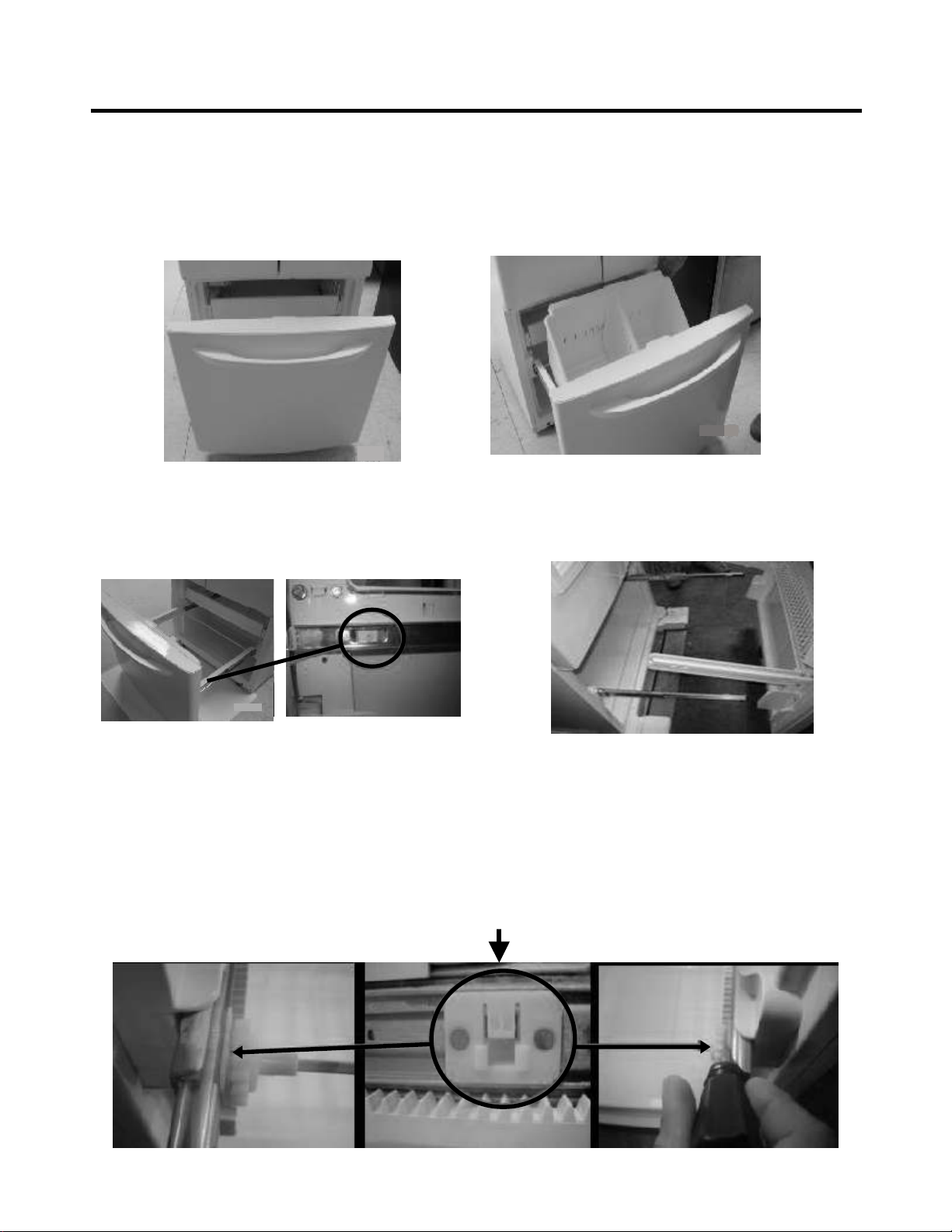
3-8 HOW TO REMOVE AND REINSTALL THE PULL OUT DRAWER
3-8-1 FOLLOW STEPS TO REMOVE
- 9 -
Step 1) Open the freezer door.
Step 3) Remove the two screws from the guide rails (one
from each side).
Step 2) Remove the lower basket.
Step 4) Lift the freezer door up to unhook it from the rail
support and remove.
Pull both rails to full extension.
Step 5) First: Remove the gear from the left side first by releasing the tab behind the gear, place a screwdriver between the
gear and the tab and pull up on the gear.
Second: Remove the center rail.
Third: Remove the gear from the right side by following the same steps for the left side.
NOTE: THIS TAB MUST BE PUSHED IN TO RELEASE THE GEAR.
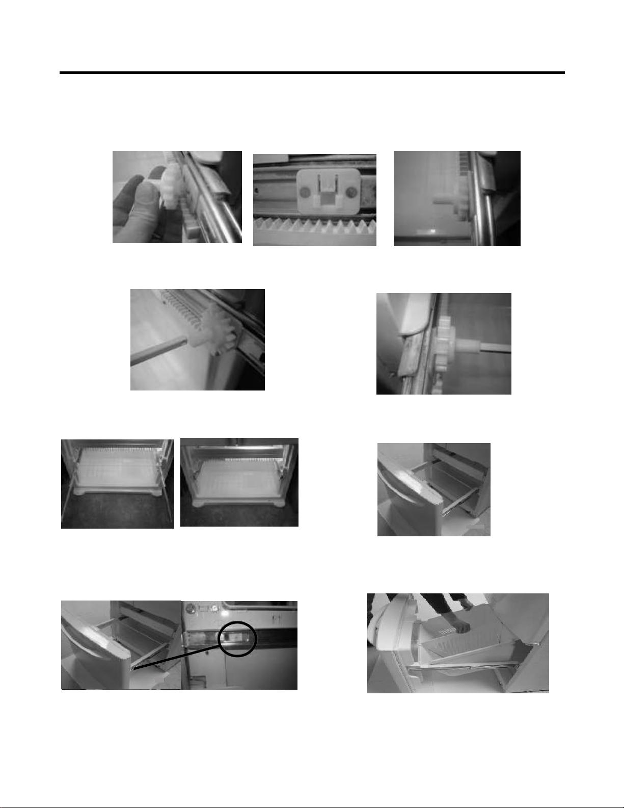
3-8-2 FOLLOW STEPS TO REINSTALL
Step 1) Reinstall the right side gear into the clip.
Step 2) Insert the rail into the right side gear. Gears do not
need to be perpendicular to each other.
Step 4) The rail system will align itself by pushing the rails
all the way into the freezer section.
Pull the rails back out to full extension.
Step 6) Reinstall the two screws into the guide rails
(one from each side).
Step 3) Insert the rail into the left side gear, and insert the
gear into the clip.
Step 5) Reinstall the freezer door by inserting the rail tabs
into the guide rail.
Step 7) Reinstall the lower basket, and close the freezer
door.
- 10 -
- 11 -
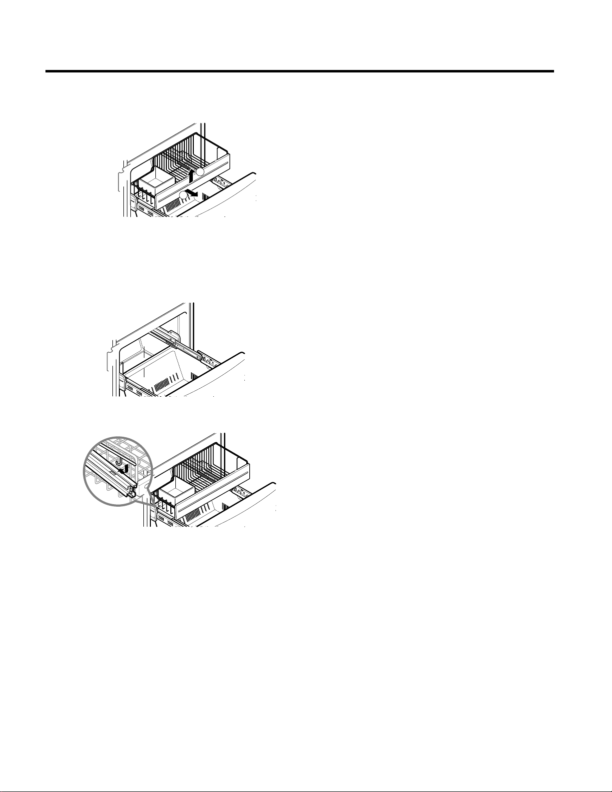
To remove, lift basket up and pull out straight out.
3.8.3 GLIDE OUT DRAWER BASKET
2.
1.
To Install, pull both rails out to full extension.
Hook the basket supports into the rail tabs and push to
the back of compartment.
1
2
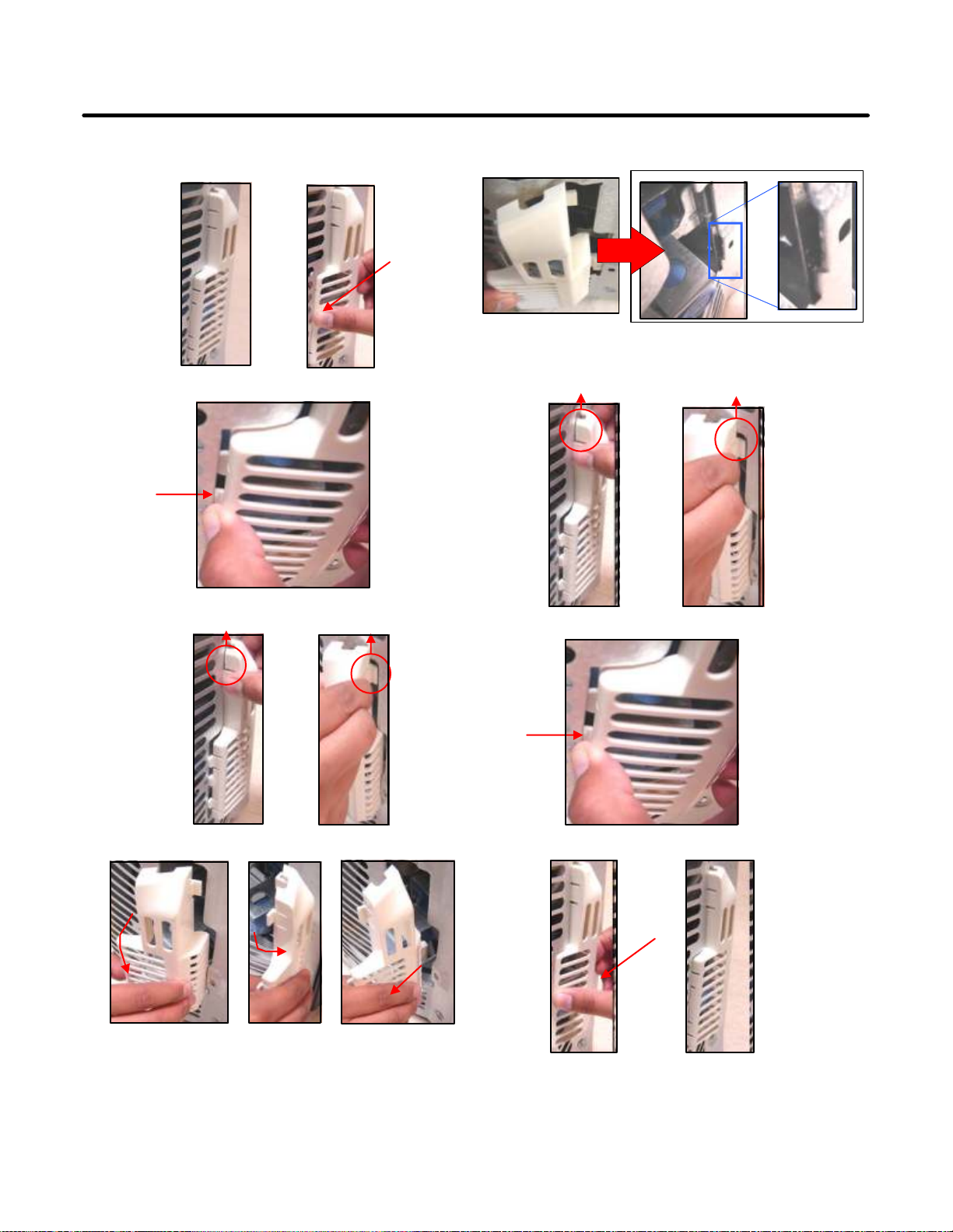
3-9 Cover Valve
- Disassemble
1. Push to inside the cover valve.
2. Push to the right and release.
3. Release hook a & b
4. Turn the cover valve 120° as shown in the picture, then
release it.
b
- Assemble
1. Insert the cover valve as shown in the picture, push to
insert (may need force).
2. Insert hook a & b
3. Push to the right to insert the cover valve.
4. Then push to inside to assembly.
a
b
a
- 12 -

4. COMPRESSOR ELECTRICAL
- 13 --
PTC STARTER
SEALED
TERMINAL
COMPRESSOR
MOTOR
C
M
S
M
3
6
5
2
S
PTC
N
L1
OVERLOAD PROTECTOR
Resistance Starter Capacitor Running
4-1 COMPRESSOR
4-1-1 Role
The compressor intakes low temperature and low pressure
gas from the evaporator of the refrigerator and compresses
this gas to high temperature and high pressure gas. It then
delivers the gas to the condenser.
4-1-2 Composition
The compressor includes overload protection. The PTC
starter and OLP (overload protector) are attached to the
outside of the compressor. Since the compressor is
manufactured to tolerances of 1 micron and is hermetically
sealed in a dust and moisture-free environment, use extreme
caution when repairing it.
4-1-3 Note for Usage
(1) Be careful not to allow over-current.
(2) If compressor is dropped or handled carelessly, poor
operation and noise may result.
(3) Use proper electric components appropriate to the
particular compressor in your product.
(4) Keep compressor dry.
If the compressor gets wet (in the rain or a damp
environment) and rust forms in the pin of the Hermetic
Terminal, poor operation and contact may result. If the
hermetic connector rusts out or fails, refrigerant and oil will be
expelled into the contact area, probably resulting in smoke
and fire.
(5) When replacing the compressor, be careful that dust,
humidity, and soldering flux don´t contaminate the inside of
the compressor. Contamination in the cylinder may cause
noise, improper operation or even cause it to lock up.
4-2 PTC-STARTER/ COMBO
4-2-1 Composition of PTC- Starter
(1) PTC (Positive Temperature Coefficient) is a no-contact
semiconductor starting device which uses ceramic material
consisting of BaTiO3.
(2) The higher the temperature is, the higher the resistance
value. These features are used as a starting device for the
motor.
4-2-2 Role of PTC-Starter
(1) The PTC is attached to the Sealed Compressor and is
used for starting the motor.
(2) The compressor is a single-phase induction motor. During
the starting operation, the PTC allows current flow to both the
start winding and main winding.
4-2-3 Combo TSD
TSD (Time Starting Device) is a new electronic starting
system for high efficiency compressors due to the following
characteristics:
(1) Combo concept-overload protector, electronic board and
cover in a single casing.
(2) Fully electronic concept.
(3) Full integration of starting and protection devices.
(4) Free from mechanical and electromagnetic noises.
4-2-4 Role of Combo TSD
(1) The combo is attached to the sealed compressor and is
used for the operation and protect the motor.
(2) The compressor is a single phase induction motor. During
the starting and operation, the combo allows current flow to
both the start and main winding.
4-2-5 PTC/Combo - Applied Circuit Diagram
Starting Method for the Motor
PTC DIAGRAM
COMBO DIAGRAM
4-2-6 Motor Resarting and PTC/ Combo Cooling
(1) It requires approximately 5 minutes for the pressure to
equalize before the compressor can restart.
(2) The PTC/Combo device generates hea during operation.
Therefore, it must be allowed to cool before the compressor
can restart.
4-2-7 Relation of PTC-Starter / Combo and OLP
(1) If the compressor attempts to restart before the
PTC/Combo device is cooled, the PTC/Combo device will
allow current to flow only to the main winding.
(2) The OLP will open because of the over current condition.
Thissame process will continue (3 to 5 times) when the
compressor attempts to restart until the PTC/Combo device
has cooled. The corret OLP must be properly attached to
prevent damage to the compressor.
Parts may appear physically identical but could have different
electrical ratings. Replace parts by part number and model
number. Using an incorrect part could result in damage to the
product, fire, injury, or possibly death.
SEALED
TERMINAL
COMPRESSOR
MOTOR
S
S
N
C
L
M
M
AS
T R
T
MA
IN
LINE
PTC
OLP
- 14 -
Customer part
number
Lot code/
date code
330 FBYY -S1 BOX98
12345678
Physical
termination
part number
Electrical
characteristics
part number
(OVERLOAD PROTECTOR cross section)
4-2-8 Note for using the PTC-Starter / Combo
(1) Be careful not to allow over-voltage and over-current
(2) Do not drop or handle carelessly.
(3) Keep away from any liquid.
If liquid such as oil or water enters the PTC/Combo,
PTC/Combo materials may fail due to breakdown of their
insulating capabilities.
(4) If the exterior of the PTC/Combo is damaged, the
resistance value may be altered. This can cause damage to
the compressor and result in a no-start or hard-to-start
condition.
(5) Always use the PTC/Combo designed for the compressor
and make sure it is properly attached to the compressor.
Parts may appear physically identical but could have different
electrical ratings. Replace parts by part number and model
number. Using an incorrect part could result in damage to the
product, fire, injury, or possibly death.
4-3 OLP (OVERLOAD PROTECTOR)
4-3-1 Definition of OLP
(1) OLP (OVERLOAD PROTECTOR) is attached to the
compressor and protects the motor by opening the circuit to
the motor if the temperature rises activating the bimetal
spring in the OLP.
(2) When high current flows to the compressor motor, the
bimetal wors by heating the heater inside the OLP, and the
OLP protects the motor by cutting off the current flowing to
the compressor motor.
4-3-2 Role of the OLP
(1) The OLP is attached to the sealed compressor used for
the refrigerator. It prevents the motor coil from being started
in the compressor.}
(2) For normal operation of the OLP, do not turn the adjust
screw of the OLP in anyway.
4-4 TO REMOVE THE COVER PTC (only if applies)
(1) Remove the cover Back M/C.
(2) Disconnect two housing upper side of comp connected in.
(3) Loosen two screws on comp base.
(4) Use a L-shaped flap tool to pry off the cover.
(5) Assembly in reverse order of disassembly.
4-5 TO REMOVE THE COMBO (only if applies)
(1) Remove the cover Back M/C.
(2) Disconnect two housing upper side of comp connected in.
(3) Loosen two screws on comp base.
(4) Use a flat screwdriver to take off the clip from the lower
side.
(5) Take the combo off.
(6) To assembly the side with the “U” form is hooked in the
central part of the compressor base.
(7) Press the “A” point and lift the “B” point to hook to
compressor.
(5) (5) (5)
111
222
333
A
B
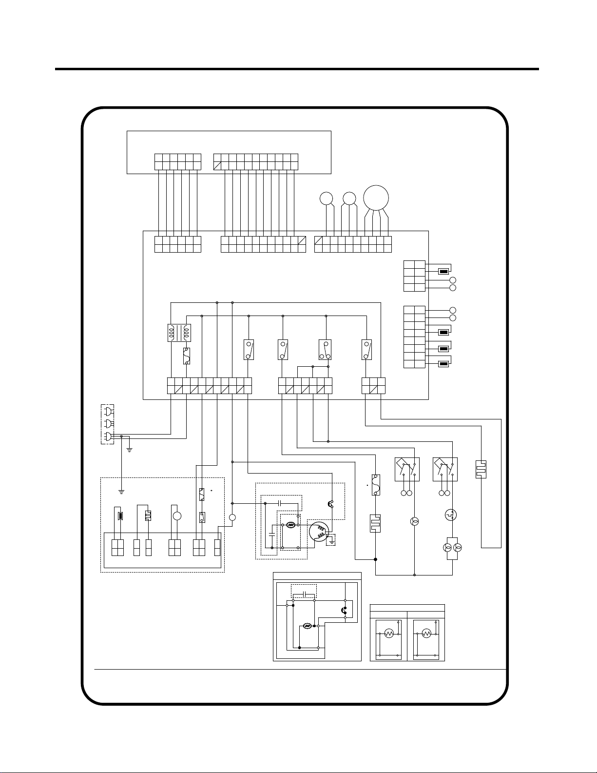
5. CIRCUIT DIAGRAM
- 15 -
10
BO
PR
Cr
DOOR S/W-R
PK
3
3
6
L1
BL
9
/WH
2
WH
BK
N
CON1
CON7
V
RD
1
BL
2
4
/BK
CON2
10
YL:YELLOW
SB:SKY BLUE
8
8
4
EG COMP'
9
BL:BLUE
1
3
BK
DOOR S/W-F
PWB (PCB) ASSEMBLY, ICE MAKER
COMP' EARTH PART AND COMP' ACCESSORIES ON CIRCUIT
7
GY
BK
F-DOOR
BL
YL
BL
SB
FUSE-M
BK:BLACK
11
S
5
RD
WH
A
2
RD
nc
POWER
STEPPING
BL
F-LAMP
COMBO KIT(PTC+OLP)
WH
BN
/RD
2
1
RT-SENSOR
WH
3
GN/YL
WH
BL
W/VALVE
BL
CON8
3
(GN)
BL
RD
/BK
4
GN:GREEN
PK
BN
7
FRENCH DOOR HEATER
BL
BO:BRIGHT ORANGE
4
BO
1
BN
7
DIAGRAM ARE SUBJECTED TO CHANGE IN DIFFERENT
8
RD
PK
CON101
PK
YL
M
1
2
BL
(GN)
BN
M
2
6
7
THERMOSTAT
2
/WH
2
CON102
WH:WHITE
2
SB
ICE MAKER PART
BO
BK
GY
BL
PERCEPTION S/W
1
nc
5
POWER
ICE SENSOR
ICE MAKER
OLP
MC,MQ COMP'
Cs
/YL
CON5
8
BO
R-SENSOR
BL
1
C-FAN
BL
COMP' ACCESSORIES
9
WH
OLP
5
RD
CON5
CON1
1
* P.T.C START OPTION
CON6
6
6
4
1
(GN)
1
3
5
BK
4
WH
2
3
PTC STARTER
4
CAPACITOR PART
nc
/BK
BL
BL
5
YL
6
N
PR
F-SENSOR
4
D
5 3
PR
WH
TWO SWITCHES CONNECTED IN CON2 TERMINALS 1 AND 3,
YL
BO
nc
FUSE-M
C
BN:BROWN
2
BN
BL
GN
1
(GN)
11
BN
S
6
6
R-LAMPS
3
5
SB
com
9
BK
HEATER,SHEATH
D
2
1
8
BN
YL
HEATER,
6
COMP' EARTH
SB
BN
BL
R-DOOR
RD:RED
S/W
M
1
SHEATH
BK
Cs
/YL
SB
MOTOR
RD
PK
WH
Cr
DEF-SENSOR
/BK
MOTOR
4
2
10
PTC
3
PR:PURPLE
/RD
5
11
CON4
BL
CON6
BL
L
RD
2
SB
SB
SUPPLY
BK
PART
4
(72 C)
6
com
4
WH
RD
5
CAPACITOR PART
SB
* ALTERNATIVE COMP' ACCESSORIES
4
WH
WH
*PLUG TYPE, ICE MAKER PART, CAPACITOR PART,
6
L
PWB(PCB) ASSEMBLY, MAIN
SB
6
P.T.C START OPTION, DOOR S/W-R REPRESENTS
SB
YL
(98 C)
PK:PINK
PERCEPTION S/W
PART
BO
GY
BK
1
BO
FUSE1
B
GN
5
1
BL
3
2
BK
7
2
com
F-FAN
C
BL
4
WH
OLP
GY:GREY
WH
CON3
5
SB
BN
1
6
2
CON2
GN/YL
10
BN
BN
CON4
A
I/MAKER
COMP' EARTH
com
3
3
CORD
YL
3
7
B
5
PWB(PCB) ASSEMBLY,DISPLAY-R
CON3
PR
LOCALITIES AND MODEL TYPE.
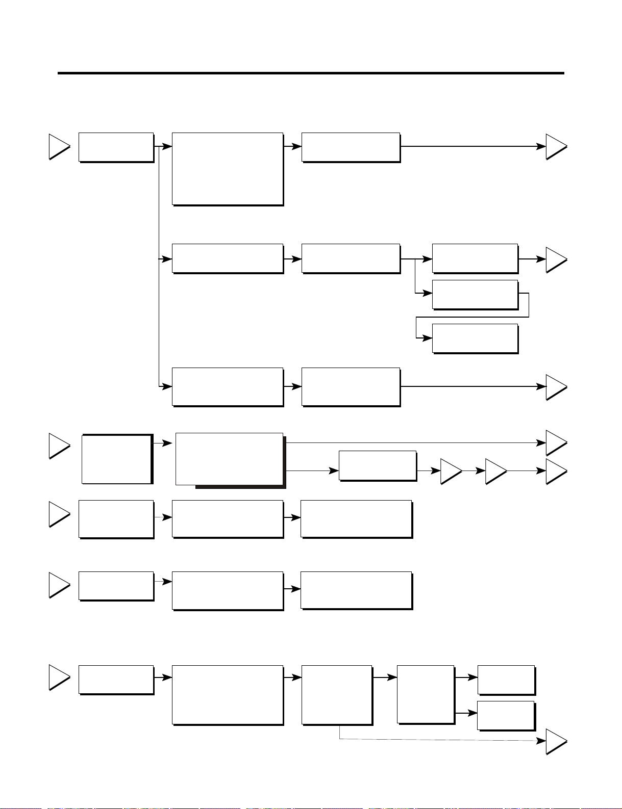
6. TROUBLESHOOTING
- 16 -
6-1 COMPRESSOR AND ELECTRIC COMPONENTS
1
2
3
4
5
2
5
5
3
5
1
43
YES
NO
YES
Open or short
YES
YES
NO
NO
Power Source.
No voltage.
(Rated voltage
±10%)?
Replace OLP.
Reconnect.
Check resistance of
two terminals in
PTC/Starter/Combo
Did
compressor
start?
Compressor
is OK
Replace the
compressor
Check connection
condition.
OLP disconnected?
Advise customer that
power supply needs to be
checked by an electrician.
Supply
voltage rating
with ±10%.
Applied voltage isn't
in acceptable range.
(115V ±10%)
Remove PTC-Starter/Combo
from compressor and
measure voltage
between Terminal C of
compressor and
terminal 5 or 6 of PTC/Combo
Check resistance of
PTC-Starter/ Combo
Check resistance of two
terminals in OLP.
Check the power supply
under load.
(Compressor attempting
to re-start after being off
for 5 minutes).
.
Check
resistance of
PTC-Starter.
Check OLP.
Check
starting state.
Check resistance
of motor
compressor.
Replace
compressor
Refer to Page 13.
Check
resistance of
motor
compressor.
The resistance between pins should be
between 1 and 50 ohms. The resistance to
ground should be infinite.
or short to
ground
Check the resistance
between M-C, S-C and M-S
in motor compressor.
Check each pin to ground.
- 17 -
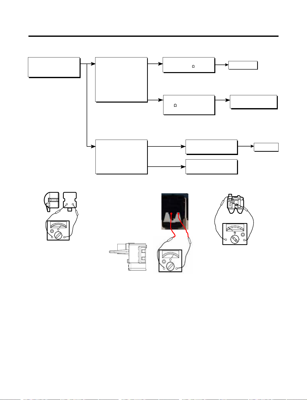
6-2 PTC/COMBO AND OLP
Shows continuity
Open
Separate PTC-Starter/Combo
from Compressor and
measure resistance
between No. 5 and 6
of PTC-Starter with a
Tester.
(Figure 19a and 19b)
Observation value is
115V/60Hz : 6.8 ±30%
The resistance value
is 0 (short) or
8(open).
Check another
electric component.
Replace OLP.
Replace PTC-
Starter/Combo
Normal operation of
compressor is impossible
or poor.
Separate OLP from
compressor and check
resistance value between
two terminals of OLP with a
tester.
(Figure 20)
at room temperature
PTC/Combo OK
OLP OK
65
Figure 19a
Figure 19b
Figure 20
?

- 18 -
•Not cooling at all
•Poor cooling performance
Compressor
doesn't run
.
Compressor runs
poorly.
Check starting
voltage.
Check for open short or
incorrect resistance readings
in the following components
a. Starting devices
b. OLP
c. Compressor coil
d.Wiring harness
Low voltage.
Short, open, or broken.
Poor contact
or shorted.
Coil open or shorted.
Poor contact
or shorted.
Poor or broken or
open contact.
Shorted.
Lack of capacity.
Replace
indicated component.
Advise customer that
the power supply
needs to be checked
by an electrician.
Replace
indicated component.
Cause
Check voltage at
starting devices.
Check current flowing
In run winding of
Compressor.
Check rating of OLP.
Fan motor
doesn't run.
Wire is open or
shorted.
Coil is shorted
or open.
Open.
Open.
Replace
defrost heater.
Replace
indicated component.
Replace
indicated component.
Check wiring circuit.
Check Fan Motor .
Check current flow in
the following
components:
Sensor
Fuse-M
Check resistance flow in
the defrost heater.
6-3 OTHER ELECTRICAL COMPONENTS
Heavy frost buildup on
evaporator
13 - 15 V
OLP: 4TM319NFBYY
Temp. 120°C
6-4 SERVICE DIAGNOSIS CHART
- 19 -
COMPLAINT POINTS TO BE CHECKED REMEDY
•Other possible problems:
Check components
of the defrosting
circuit.
Check the
refrigeration system.
Not
defrosting
The system
is faulty.
Perform sealed
system repair.
No Cooling.
Cools poorly.
Food in the
Refrigerator
is frozen.
Condensation or ice
forms inside
the unit.
Condensation forms
On the Exterior Case.
There is abnormal
noise.
Door does not
close well.
Ice and foods
smell unpleasant.
•Is the power cord unplugged from the outlet?
•Check if the power switch is set to OFF.
•Check if the fuse of the power switch is open.
•Measure the voltage of the power outlet.
•Check if the unit is placed too close to the wall.
•Check if the unit is placed too close to the stove,
Gas cooker, or in direct sunlight.
•Is the ambient temperature too high or
the room door closed?
•Check if food put in the refrigerator is hot.
•Did you open the door of the unit too often
or check if the door is sealed properly?
•Check if the Control is set to Warm position
.
Is food placed in the cooling air outlet?
Check if the control is set to colder position .
Is the ambient temperature below 5° C (41°F)?
Is liquid food sealed?
Check if food put in the refrigerator is hot.
Did you open the door of the unit too
often or check if the door is sealed properly?
Check if the ambient temperature and humidity
of the surrounding air are high.
Is there a gap in the door gasket?
Is the unit positioned in a firm and even place?
Are any unnecessary objects placed
Beside side of the unit?
Check if the Drip Tray is not firmly attached.
Check if the cover of the compressor enclosure
Is lose.
Check if the door gasket is dirty with
an item like juice.
Is the refrigerator level?
Is there too much food in the refrigerator?
Check if the inside of the unit is dirty.
Are foods with a strong odor unwrapped?
The unit smells of plastic.
Plug into the outlet.
Set the switch to ON.
Replace the fuse.
If the voltage is low, correct the wiring.
Place the unit about 4 inches (10 cm) from the wall.
Place the unit away from these heat sources.
Lower the ambient temperature.
Put in foods after they have cooled down.
Don't open the door too often and close
it firmly.
Set the control to Recommended position
Place foods in the high-temperature section.
(front part)
Set the control to Recommended position
Set the control to
Warm position
.
Seal liquid foods with wrap.
Put in foods after they have cooled down.
Don't open the door too often and close
It firmly.
Wipe moisture with a dry cloth. It will disappear
in low temperature and humidity.
Adjust the leveling screw, and position the
refrigerator in a firm place.
Remove the objects.
Fix the drip tray firmly in the original position.
Place the cover in its original position.
Clean the door gasket.
Position in a firm place and level the
leveling screw.
Make sure food stored in shelves does not prevent
the door from closing.
Clean the inside of the unit.
Wrap foods that have a strong odor.
New products smell of plastic, but this
will go away after 1-2 weeks.
Is it properly installed?
Freezer or evaporator
is full of frost
Repair or replace the gasket as needed.
•
•
•
•
•
•
•
•
•
•
•
•
•
•
•
•
•
•
•
•
•
•
•
•
•
•
•
•
•
•
•
•
•
•
•
•
•
•
•
•
•
•
•
•
•
•

6-5 REFRIGERATION CYCLE
- 20 -
* Troubleshooting Chart
¥
¥
¥
¥
¥
¥
¥
¥
¥
¥
¥
¥
¥
CAUSE
TEMPERATURE
OF THE
COMPRESSOR
REMARKS
STATE OF
THE UNIT
STATE OF THE
EVAPORATOR
LEAKAGE
PARTIAL
LEAKAGE
Freezer
compartment and
refrigerator don’t
cool normally
COMPLETE
LEAKAGE
CLOG
CLOG
NO
COMPRE-
SSION
Freezer
compartment and
refrigerator don’t
cool normally
Freezer
compartment and
refrigerator don’t
cool normally
Freezer
compartment and
refrigerator don’t
cool.
Cooling operation
stops periodically.
Freezer and
refrigerator don’t
cool.
No compressing
operation.
Low flowing sound of
refrigerant is heard and frost
forms in inlet only.
Flowing sound of refrigerant
is not heard and frost isn’t
formed.
Flowing sound of refrigerant
is heard and frost forms in
inlet only.
Flowing sound of refrigerant is
not heard and frost isn’t
formed.
Flowing sound of refrigerant is
not heard and frost melts.
Low flowing sound of
refrigerant is heard and frost
forms in inlet only.
Flowing sound of refrigernat is
not heard and there is no
frost.
A little higher than
ambient
temperature.
- Refrigerant level is low due to a
leak.
- Normal cooling is possible by
restoring the normal amount of
refrigerant and repairing the leak.
Equal to ambient
temperature.
- No discharging of refrigerant.
- Normal cooling is possible by
restoring the normal amount of
refrigerant and repairing the leak.
A little higher than
ambient
temperature.
- Normal discharging of the
refrigerant.
- The capillary tube is faulty.
Equal to ambient
temperature.
- Normal discharging of the
refrigerant.
Lower than ambient
temperature.
- Cooling operation restarts when
heating the inlet of the capillary
tube.
Alittle higher than
ambient
temperature.
- Low pressure at high side of
compressor due to low
refrigerant level.
Equal to ambient
temperature
- Nopressure in the high pressure
part of the compressor.
E
S
T
I
T
O
N
R
R
C
I
MOISTURE
RESTRICTION
LOW
COMPRESSION
I
N
E
F
F
I
C
I
E
T
N
C
O
M
R
E
S
OR
P
S
Loading...