


Kenmore 795.79309.900, 795.79019.900, 795.79302.900, 795.79303.900, 795.79304.900 Service Manual
...R
TOP FREEZER REFRIGERATOR
REFRIGERATOR
SERVICE MANUAL
CAUTION
BEFORE SERVICING THE UNIT,
READ THE SAFETY PRECAUTIONS IN THIS MANUAL.
MODELS:
795.79012.900
795.79013.900
795.79014.900
795.79019.900
795.79302.900
795.79303.900
795.79304.900
795.79309.900
Sears, Roebuck and Co., Hoffman Estates, IL60179 U.S.A.
www.sears.com

CONTENTS
SAFETY PRECAUTIONS ..................................................................................................... |
2 |
|
1. SPECIFICATIONS ............................................................................................................ |
3 |
|
2. PARTS IDENTIFICATION ................................................................................................. |
5 |
|
3. DISASSEMBLY ................................................................................................................ |
6 |
|
3.1 |
Door ............................................................................................................................ |
6 |
3.2 |
Door switch ................................................................................................................. |
6 |
3.3 |
Fan and fan motor ....................................................................................................... |
7 |
3.4 |
Defrost control assembly ............................................................................................. |
7 |
3.5 |
Lamp ........................................................................................................................... |
7 |
3.6 |
Control box-refrigerator ............................................................................................... |
7 |
4. COMPRESSOR ELECTRICAL ....................................................................................... |
8 |
|
4.1 |
Compressor ................................................................................................................. |
8 |
4.2 |
PTC-Starter/ COMBO ................................................................................................. |
8 |
4.3 |
OLP (overload protector) ............................................................................................. |
9 |
5. CIRCUIT DIAGRAM ......................................................................................................... |
10 |
|
6. TROUBLESHOOTING ...................................................................................................... |
11 |
|
6.1 |
Compressor and electric components ......................................................................... |
11 |
6.2 PTC/ COMBO and OLP .............................................................................................. |
12 |
|
6.3 |
Other electrical components ....................................................................................... |
13 |
6.4 |
Service diagnosis chart ............................................................................................... |
14 |
6.5 |
Refrigeration cycle ...................................................................................................... |
15 |
7. OPERATION PRINCIPLE AND REPAIR METHOD OF ICEMAKER ............................... |
16 |
|
7.1 |
Operation principle ...................................................................................................... |
16 |
7.2 |
Ice maker functions ..................................................................................................... |
17 |
8. DESCRIPTION OF FUNCTION & CIRCUIT OF MICOM ................................................ |
18 |
|
8.1 |
Function ...................................................................................................................... |
18 |
8.2 |
PCB function ............................................................................................................... |
21 |
8.3 |
Resistance specification of sensor .............................................................................. |
22 |
9. EXPLODED VIEW AND REPLACEMENT PART LIST .................................................... |
27 |
|
SAFETY PRECAUTIONS
Please read the following instructions before servicing your refrigerator.
1.Check the refrigerator for electrical faults.
2.To prevent electric shock, unplug before servicing.
3.Always check line voltage and amperage.
4.Use standard electrical components or cause your skin to freeze and stick to the surfaces inside the freezer.
5.Don´t touch metal poducts in the freezer with wet hands. This may cause frostbite.
6.Prevent water from spiling onto electric elements or the machine parts.
7.Close the top door before opening the bottom door. Otherwise, you might hit your head when you stand up.
8.When tilting the refrigerator, remove any materials on the refrigerator, especially the glass shelves and stored food.
9.When servicing the evaporator, wear cotton gloves. This is to prevent injuries from the sharp evaporator fins.
10.Service on the refrigerator should be performed by a qualified technician. Sealed system repair must be perdormed by a CFC certified technician.
- 2 -

1. SPECIFICATIONS
1-1 DISCONNECT POWER CORD BEFORE SERVICING IMPORTANT RECONNECT ALL GROUNDING DEVICES.
All parts of this appliance capable of conducting electrical current are grounded. If grounding wires, screws, straps, clips, nuts or washers used to complete a path to ground are removed for service, they must be returned to their original position and properly fastened.
1-2 IMPORTANT NOTICE
This information is intended for use by individuals possessing adequate backgrounds of electrical, electronic and mechanical experience. Any attempt to repair a major appliance may result in personal injury and property damage. The manufacturer or seller cannot be responsible for the interpretation of this information, nor can it assume any liability in connection with its use.
1-3 ELECTRICAL SPECIFICATIONS |
|
Temperature Control (Position: MID) ............................................................................................................................................. |
-6°F to +8°F |
Defrost Control ................................................................................................................................................................................... |
Automatic |
Defrost Thermostat ..................................................................................................................................................................................... |
50°F |
Electrical Rating : 115VAC, 60Hz............................................................................................................................................................... |
1- 5 A |
Maximum Current Leakage ..................................................................................................................................................................... |
0.5mA |
Maximum Ground Path Resistance .................................................................................................................................................. |
0.14 Ohms |
Energy Consumption...................................................................................................................................... |
19 cu.ft. 394kWh/yr (Energy Star) |
|
22 cu.ft. 422kWh/yr (Energy Star) |
1-4 NO LOAD PERFORMANCE |
|
Control Position: MID/MID |
|
And Ambient of: ....................................................................... |
70°F |
Fresh Food, °F............................................................... |
33°F to 41°F |
Frozen Food, °F.............................................................. |
-4°F to +4°F |
Percent Running Time........................................................ |
25%-35% |
.................................................................................................. 90°F
......................................................................................33°F to 41°F
...................................................................................... -4°F to +4°F
.......................................................................................... 45%-60%
1-5 REFRIGERATION SYSTEM |
|
1-6 INSTALLATION |
|
Minimum Compressor Capacity Vacuum |
...................................21 in |
Clearance must be provided for air circulation. |
|
Minimum Equalized Pressure |
49PSIG |
AT TOP |
2 in |
@70°F...................................................................... |
|||
@90°F...................................................................... |
56PSIG |
AT SIDES.......................................................................................... |
2 in |
Refrigerant R134a................................................................... |
5.47oz |
AT REAR.......................................................................................... |
2 in |
Compressor ................................................................... |
700 BTU/hr |
|
|
- 3 -
PERFORMANCE DATA
(NORMAL OPERATING CONDITIONS)
AMB |
WATTS |
SYSTEM PRESSURE (PSIG) |
|||
HIGH SIDE |
LOW SIDE |
||||
|
|
|
|||
70°F |
98 (+10 |
/ -10) |
98 (+5 / -3) |
(-5) to (-2) |
|
90°F |
98 (+10 |
/ -10) |
132 (+3 / -3) |
(-4) to 1 |
|
110°F |
103 (+5 |
/ -5) |
180 (+5 / -5) |
(-2) to 3 |
|
|
|
|
|
|
|
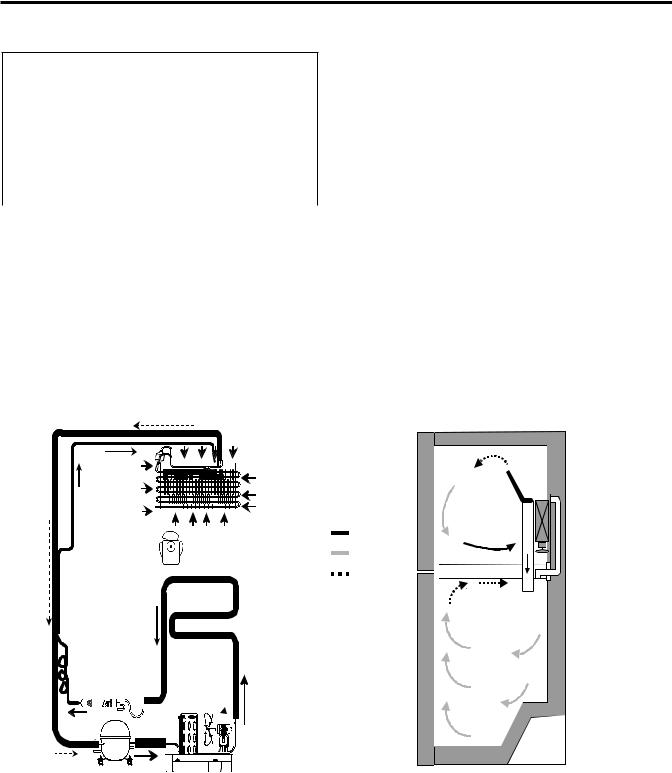
1-8 AIR FLOW
1-7 REPLACEMENT PARTS
Relay (PTC) |
19 cuft |
22 cuft |
6748C-0004D 6748C-0004D |
||
Overload Protector (OLP).......... |
6750C-0005P 6750C-0005P |
|
Defrost Thermostat ................. |
4781JK2001A |
4781JK2001A |
Defrost Heater ........... ............... |
5300JK1003D |
5300JK1003J |
Evaporator Fan Motor ............. |
4681JK1004A |
4681JK1004A |
Capacitor .................................... |
0CZZJB2012J |
0CZZJB2012J |
Compressor (Hi-side)................. |
TCA33414101 |
TCA33414101 |
Evaporator (Lo-side) .................. |
5421JJ0003A |
5421JJ0002A |
Condenser ................................. |
5403JJ1008A |
5403JJ1008A |
Dryer........................................... |
5851JJ2002F |
5851JJ2002F |
Condenser Fan Motor................. |
4681JB1029J |
4681JB1029J |
Temperature Control .................. |
EBR59400501 EBR59400501 |
|
Main Control ............................... |
EBR41531307 EBR41531307 |
|
FREEZER
|
COLD AIR |
EVAPORATOR FAN |
EVAPORATOR |
MIXED AIR |
|
|
AIR RETURN TO |
|
EVAPORATOR |
CONTROL
HOT LOOP
EVAPORATOR |
FRESH FOOD |
DRYER
 CONDENSER FAN
COMPRESSOR CONDENSER
- 4 -
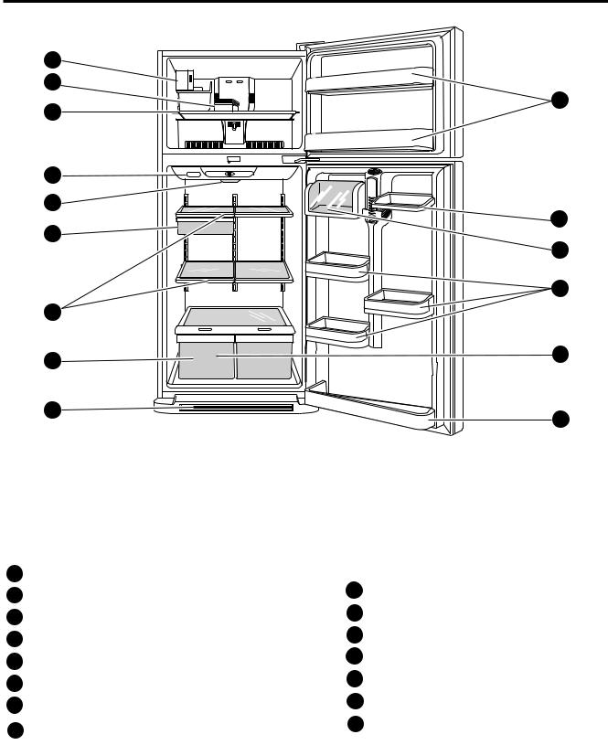
2. PARTS IDENTIFICATION
A |
B |
J |
C |
D |
E |
K |
F |
L |
M |
G |
N |
H |
I |
O |
Use this section to become more familiar with the parts and features. Page references are included for your
convenience.
NOTE: This guide covers several different models. The refrigerator you have purchased may have some or all of the items listed below. The locations of the features shown below may not match your model.
A |
CustomCube Ice maker |
I Base Grille |
B |
Ice Bin |
|
C |
Freezer Shelf |
J Freezer Door Bin |
D Digital Sensor Control |
K Dairy Corner |
|
E |
Refrigerator Light |
L Can Dispenser |
|
||
F |
Snack Pan |
M Door Bin |
|
||
G |
Shelves |
N Refrigerator Door Rack |
H Crisper |
O Vitabox (Inside)* |
|
|
Keeps fruits and vegetables fresh and crisp |
|
*On some models
- 5 -
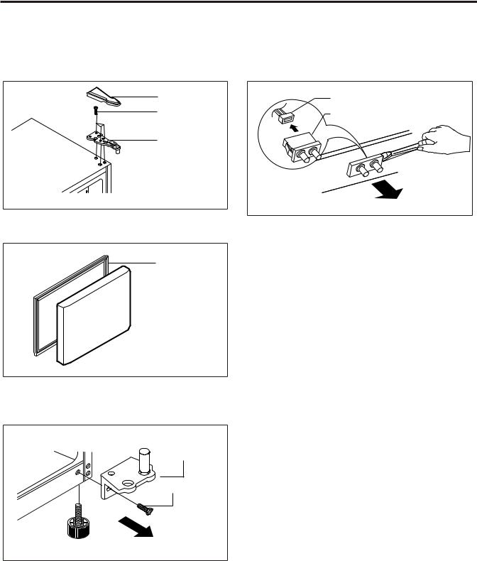
3. DISASSEMBLY
3-1 DOOR
Freezer Door
1.Remove the hinge cover by pulling it upwards.
2.Loosen hexagonal bolts attaching the upper hinge to the body and lift the freezer door.
HINGE COVER
BOLT
HINGE
Figure 1
3.Pull out the door gasket to remove from the door foam assembly.
GASKET
Figure 2
Refrigerator Door
1.Loosen hexagonal bolts attaching the lower hinge to the body to remove the refrigerator door only.
LOWER HINGE
BOLT
Figure 3
2.Pull out the door gasket to remove from the door foam assembly.
3-2 DOOR SWITCH
1.To remove the door switch, pry it out with a slotted-type driver, as shown in (Figure 4).
2.Disconnect the lead wire from the switch.
LEAD WIRE |
DOOR SWITCH |
Figure 4 |
- 6 -
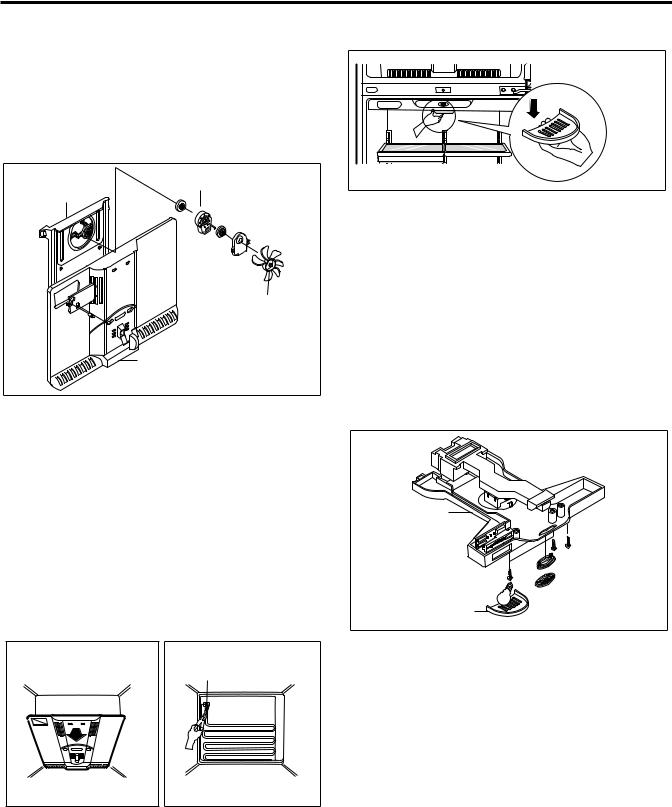
3-3 FAN AND FAN MOTOR
1.Remove the freezer shelf. (If your refrigerator has an icemaker, unplug and remove the icemaker first).
2.Remove the screw of the cover grille fan
3.Remove the grille by pulling it out and by loosening a screw.
4.Remove the Fan Motor assembly by loosening 4 screws and disassemble the shroud.
5.Pull out the fan and separate the Fan Motor and Bracket.
FAN MOTOR
SHROUD
BRACKET 
FAN
GRILLE
Figure 5
3-5 LAMP |
Figure 8
3-5-1 Refrigerator Compartment Lamp
1.Unplug the power cord from the outlet.
2.Remove refrigerator shelves.
3.Release the hooks on both ends of the lamp shield and pull the shield downward to remove it.
4.Turn the lamp counterclockwise.
5.Assemble in reverse order of disassembly. Replacement bulb must be the same specification as the original (Max. 40 W-1EA).
3-6 CONTROL BOX-REFRIGERATOR
1.First, remove all shelves in the refrigerator. Then remove the Refrigerator Control Box by loosening 2 screws.
3-4 DEFROST CONTROL ASSEMBLY
Defrost Control assembly consists of Defrost Sensor and FUSE–M.
Defrost sensor functions to defrost automatically. It is attached to metal side of the Evaporator and senses Temperature. At the temperature of 162°F(72°C), it stops the emission of heat from the Heater.
Fuse-M is a safety device for preventing over-heating of the Heater when defrosting.
1.Pull out the grille assembly. (Figure 6)
2.Separate the connector of the Defrost Control assembly and replace the Defrost Control assembly after cutting the Tie Wrap. (Figure 7)
GRILLE ASSEMBLY |
DEFROST-CONTROL |
||||
|
|
ASSEMBLY |
|||
|
|
||||
|
|
|
|
|
|
|
|
|
|
|
|
|
|
|
|
|
|
|
|
|
|
|
|
Figure 6 |
Figure 7 |
CONTROL BOX
COVER LAMP |
Figure 9 |
2.Remove the Refrigerator Control Box by pulling it downward.
3.Disconnect the lead wire on the right position and separate the lamp sockets.
- 7 -
4. COMPRESSOR ELECTRICAL
4-2-4 Role of Combo TSD
(1) The combo is attached to the sealed compressor and is used for the operation and protect the motor.
The compressor intakes low temperature and low pressure gas (2) The compressor is a single phase induction motor. During from the evaporator of the refrigerator and compresses this gas the starting and operation, the combo allows current flow to both to high temperature and high pressure gas. It then delivers the the start and main winding.
gas to the condenser.
4-1-2 Composition
The compressor includes overload protection. The PTC starter and OLP (overload protector) are attached to the outside of the compressor. Since the compressor is manufactured to tolerances of 1 micron and is hermetically sealed in a dust and moisture-free environment, use extreme caution when repairing it.
4-1-3 Note for Usage
(1)Be careful not to allow over-current.
(2)If compressor is dropped or handled carelessly, poor operation and noise may result.
(3)Use proper electric components appropriate to the particular compressor in your product.
(4)Keep compressor dry.
If the compressor gets wet (in the rain or a damp environment) and rust forms in the pin of the Hermetic Terminal, poor operation and contact may result. If the hermetic connector rusts out or fails, refrigerant and oil will be expelled into the contact area, probably resulting in smoke and fire.
(5) When replacing the compressor, be careful that dust, humidity, and soldering flux don´t contaminate the inside of the compressor. Contamination in the cylinder may cause noise, improper operation or even cause it to lock up.
4-2 PTC-STARTER/ COMBO
4-2-1 Composition of PTCStarter
(1)PTC (Positive Temperature Coefficient) is a no-contact semiconductor starting device which uses ceramic material consisting of BaTiO3.
(2)The higher the temperature is, the higher the resistance value. These features are used as a starting device for the motor.
4-2-2 Role of PTC-Starter
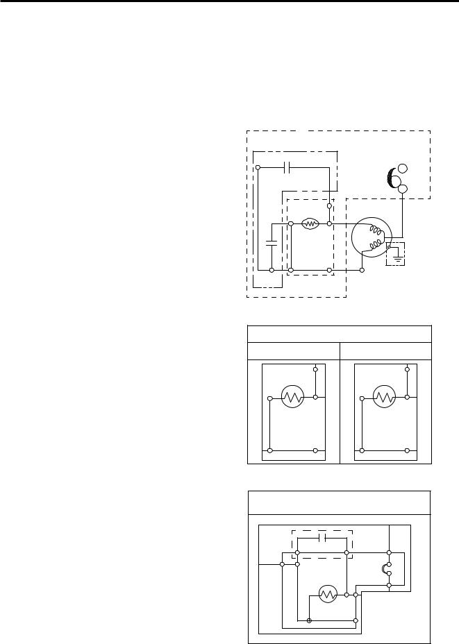
4-2-5 PTC/Combo - Applied Circuit Diagram Starting Method for the Motor
COMPRESSOR
ACCESORIES
CAPACITOR PART
|
PK |
|
|
OLP |
Cr |
|
|
|
|
|
|
|
|
|
RD |
|
2 |
|
|
Cs |
4 |
S |
|
BK |
|
5 |
|
GN |
|
|
3 |
M |
|
|
|
6 |
BL |
/YL |
|
BL |
(GN) |
|||
P.T.C |
COMP' EARTH |
|||
|
|
PART |
||
PTC
DIAGRAM
* P.T.C OPTION
LD,LQ COMP' |
EG COMP' |
|
2 |
|
3 |
4 |
5 |
4 |
6 |
3 |
6 |
2 |
5 |
(1)The PTC is attached to the Sealed Compressor and is used for starting the motor.
(2)The compressor is a single-phase induction motor. During the starting operation, the PTC allows current flow to both the start winding and main winding.
4-2-3 Combo TSD
TSD (Time Starting Device) is a new electronic starting system for high efficiency compressors due to the following characteristics:
(1)Combo concept-overload protector, electronic board and cover in a single casing.
(2)Fully electronic concept.
(3)Full integration of starting and protection devices.
(4)Free from mechanical and electromagnetic noises.
COMBO KIT
DIAGRAM
* ALTERNATIVE COMP' ACCESSORIES
|
BK |
|
|
BL |
CR |
L |
|
OLP |
|||
N |
|
||
|
PTC |
|
|
|
COMBO KIT |
||
|
(PTC+OLP) |
||
- 8 -

4-2-6 Motor Resarting and PTC/ Combo Cooling |
4-3-2 Role of the OLP |
(1)It requires approximately 5 minutes for the pressure to equalize before the compressor can restart.
(2)The PTC/Combo device generates hea during operation. Therefore, it must be allowed to cool before the compressor can restart.
4-2-7 Relation of PTC-Starter / Combo and OLP
(1)If the compressor attempts to restart before the PTC/Combo device is cooled, the PTC/Combo device will allow current to flow only to the main winding.
(2)The OLP will open because of the over current condition. Thissame process will continue (3 to 5 times) when the compressor attempts to restart until the PTC/Combo device has cooled. The corret OLP must be properly attached to prevent damage to the compressor.
Parts may appear physically identical but could have different electrical ratings. Replace parts by part number and model number. Using an incorrect part could result in damage to the product, fire, injury, or possibly death.
4-2-8 Note for using the PTC-Starter / Combo
(1)Be careful not to allow over-voltage and over-current
(2)Do not drop or handle carelessly.
(3)Keep away from any liquid.
If liquid such as oil or water enters the PTC/Combo, PTC/Combo materials may fail due to breakdown of their insulating capabilities.
(4)If the exterior of the PTC/Combo is damaged, the resistance value may be altered. This can cause damage to the compressor and result in a no-start or hard-to-start condition.
(5)Always use the PTC/Combo designed for the compressor and make sure it is properly attached to the compressor. Parts may appear physically identical but could have different electrical ratings. Replace parts by part number and model number. Using an incorrect part could result in damage to the product, fire, injury, or possibly death.
4-3 OLP (OVERLOAD PROTECTOR)
4-3-1 Definition of OLP
(1)The OLP is attached to the sealed compressor used for the refrigerator. It prevents the motor coil from being started in the compressor.}
(2)For normal operation of the OLP, do not turn the adjust screw of the OLP in anyway.
(OVERLOAD PROTECTOR cross section)
|
|
Customer part |
|
12345678 |
number |
|
Lot code/ |
|
|
|
|
330 FBYY |
-S1 BOX98 |
date code |
|
||
Electrical |
|
Physical |
characteristics |
|
termination |
part number |
|
part number |
Figure 18
(1)OLP (OVERLOAD PROTECTOR) is attached to the compressor and protects the motor by opening the circuit to the motor if the temperature rises activating the bimetal spring in the OLP.
(2)When high current flows to the compressor motor, the bimetal wors by heating the heater inside the OLP, and the OLP protects the motor by cutting off the current flowing to the compressor motor.
- 9 -

5. CIRCUIT DIAGRAM
|
|
|
|
|
|
|
|
|
PWB(PCB) ASSEMBLY, DISPLAY |
|
|
|
|
|
|
|
|
|
|
|||||||||||
|
|
|
|
|
|
|
|
|
|
|
|
2 |
1 |
3 |
4 |
5 |
6 |
|
|
|
|
|
|
|
|
|
|
|
|
|
|
|
|
|
|
|
|
|
CON101 |
|
RD BN PK YL BL PR |
|
|
|
|
|
|
|
|
|
|
|
|
|
|||||||
|
|
|
|
|
|
|
|
|
|
|
|
|
|
|
|
|
|
|
|
|
|
|
|
|
|
|
|
|||
|
|
|
|
|
|
|
|
|
|
|
|
|
|
|
|
|
|
|
|
|
|
|
RT-SENSOR |
|
|
|
||||
|
|
|
|
|
|
|
|
|
|
|
|
|
|
|
|
|
|
|
|
|
|
|
|
|
|
A |
B |
|
|
|
|
|
|
RD BN |
|
3 |
4 |
5 |
6 |
|
|
|
|
PK YL BL |
6 |
5 |
4 |
3 |
PR |
|
WH WH GY GY |
|
|
|
|||||||
|
|
|
1 |
2 |
|
|
|
11 10 9 |
8 |
7 |
2 |
1 |
|
1 |
2 |
3 |
4 |
|
|
|
||||||||||
|
|
|
CON5 |
|
|
|
|
|
|
|
|
|
|
|
|
|
|
|
|
|
CON6 |
CON8 |
|
|
|
|
|
|||
C-FAN |
|
|
|
1 |
|
CON4 |
|
|
|
|
|
|
|
|
|
|
|
|
|
|
|
|
CON7 |
1 |
|
|
|
|
||
|
|
SB |
2 |
|
|
|
|
|
|
|
|
|
|
|
|
|
|
|
|
|
|
|
|
|
|
|
||||
|
|
|
|
|
|
|
|
|
|
|
|
|
|
|
|
|
|
|
|
|
|
|
2 |
|
DEF-SENSOR |
|||||
|
|
|
BN |
3 |
|
|
|
|
|
|
|
|
|
|
|
|
|
|
|
|
|
|
|
|
|
3 BO |
|
|
|
|
F-FAN |
|
|
PR 4 |
|
|
|
|
|
|
|
PWB(PCB) ASSEMBLY, MAIN |
|
|
|
|
|
4 BO |
|
|
|
||||||||||
|
|
GY 5 |
|
|
|
|
|
|
|
|
|
|
|
|
5 WH |
|
|
|
||||||||||||
|
|
|
WH 6 |
|
|
|
|
|
|
|
|
|
|
|
|
|
|
|
|
|
|
|
|
|
6 WH |
|
|
|
||
|
|
|
|
7 |
|
|
|
|
|
|
|
|
|
|
|
|
|
|
|
|
|
|
|
|
|
|
|
|
||
|
|
|
|
|
|
|
|
|
|
|
|
|
|
|
|
|
|
|
|
|
|
|
|
|
7 |
|
|
R-SENSOR |
|
|
|
|
|
|
8 |
|
|
|
|
|
|
|
|
|
|
|
|
|
|
|
|
|
|
|
|
|
8 |
|
|
|
|
|
|
|
|
9 |
|
|
|
|
|
|
|
|
|
|
|
|
|
|
|
|
|
|
|
|
|
|
|
|
|
|
|
|
|
|
|
|
|
|
|
|
|
|
|
|
|
|
|
|
|
|
|
|
|
|
|
|
|
|
|
|
|
|
|
|
|
10 |
|
|
|
|
|
|
|
|
|
|
|
|
|
|
|
|
|
|
|
|
|
|
|
|
|
|
|
|
|
|
CON3 |
|
|
|
|
|
|
|
|
|
|
CON1 |
|
|
|
|
|
|
CON2 |
|
|
||||||
|
|
|
3 |
2 |
|
1 |
|
11 10 9 |
|
8 |
7 |
6 |
5 |
4 |
3 |
2 |
1 |
|
1 |
2 |
3 |
4 |
5 |
6 |
7 |
|
|
|
||
|
|
|
|
|
|
|
|
SB |
BN |
|
YL |
|
BL |
|
BL |
|
BK |
|
|
|
SB |
|
|
|
BN |
|
|
|
||
POWER |
|
|
|
|
|
|
SB |
BN |
|
YL |
BL |
BL |
BK |
|
|
SB |
|
|
BN |
|
|
|
||||||||
SUPPLY |
|
|
|
|
|
|
|
|
|
|
|
|
|
|
|
|
|
|
|
|
|
|
|
|
|
|
|
|
|
|
CORD |
|
|
|
|
|
|
|
|
|
|
|
|
|
|
|
|
|
|
|
|
|
|
|
|
|
|
|
|
|
|
N |
|
|
|
|
|
|
|
|
|
|
|
|
|
|
|
|
|
|
|
|
|
|
|
|
|
DOORS/W-R |
|
|
FUSE-M |
(72C) |
L |
|
|
|
|
|
|
|
|
|
|
|
|
|
|
|
|
|
|
|
|
|
|
|
|
|
nc |
nc |
|||
|
|
GN/YL |
|
|
|
|
|
|
|
|
|
|
|
|
|
|
|
|
|
|
|
|
|
|
|
com |
com |
|
|
|
|
|
|
(GN) |
|
|
|
|
|
|
|
|
|
|
|
|
CAPACITOR PART |
|
|
|
|
|
|
|
|
|
|
||||
|
|
|
|
|
|
|
|
|
|
|
|
|
|
|
|
|
|
|
|
|
|
|
|
|
|
|||||
|
|
|
|
|
|
|
|
|
|
|
|
|
|
W/VALVEI/MAKER |
|
|
|
PK |
|
|
|
|
OLP |
|
|
|
B |
|
|
|
|
|
SENSORICE |
|
HEATER, |
SHEATH |
|
M |
MAKERICE MOTOR |
BK POWER |
S/W |
|
|
|
|
|
Cs |
|
|
|
|
|
|
|
|
LAMP-R |
HEATER |
SHEATH |
|||
|
|
|
|
|
|
|
|
|
|
|
|
|
|
|
|
|
Cr |
|
|
|
|
|
|
|
|
|
A |
|
|
|
|
|
|
|
|
|
|
|
|
FUSE-M |
|
|
|
|
|
|
|
|
|
|
|
|
|
|
|
|
|
|
|
|
|
GN/YL |
|
|
|
|
|
|
|
|
(98 C) |
|
|
|
|
|
|
|
|
|
|
|
|
|
|
|
|
|
|
|
RD |
|
(GN) |
|
|
|
|
|
|
|
|
|
|
|
|
|
|
|
|
2 |
|
|
|
|
|
|
|
|
|
||||
|
|
|
|
|
|
|
|
|
|
|
V |
|
|
|
RD |
|
|
|
|
|
|
|
|
|
|
|
||||
|
|
|
|
|
|
|
|
|
|
|
|
|
|
|
|
|
|
|
|
|
S |
|
BK |
|
|
|
|
|
|
|
|
|
|
|
|
|
|
|
|
|
|
|
|
|
|
|
|
|
4 |
|
5 |
|
|
|
|
|
|
|
|
||
|
|
|
|
|
|
|
|
|
|
|
|
|
|
|
|
|
|
|
|
M |
|
GN |
|
|
|
|
|
|
||
|
|
|
|
|
|
|
|
|
|
|
|
|
|
|
|
|
|
3 |
|
6 |
|
|
|
|
|
|
|
|
||
|
|
|
|
|
|
|
|
|
|
|
|
|
|
|
|
|
|
|
|
BL |
|
/YL |
|
|
|
|
|
|
||
CON5 2 |
1WH |
CON4 |
|
1 CON3 |
|
CON2 2BK |
1WH |
CON1 2BL |
1BK |
CON6 |
1RD |
|
|
|
BL |
|
|
|
(GN) |
|
|
BL |
|
BL |
||||||
1 |
|
|
|
|
|
|
|
|
COMP' EARTH |
|
|
|
|
|
||||||||||||||||
WH |
|
|
WH |
WH |
|
|
|
|
|
|
|
|
|
|
|
|
|
P.T.C |
|
|
|
|
PART |
|
|
|
|
|
||
PWB (PCB) ASSEMBLY, ICE MAKER |
|
|
|
|
|
|
COMP' ACCESSORIES |
|
|
|
|
|
|
|
|
|
||||||||||||||
|
|
|
|
|
|
|
|
|
|
|
|
|
|
|
|
|
|
|
|
|
||||||||||
|
|
|
|
|
|
|
|
|
|
|
|
|
|
|
|
|
|
|
|
|
|
|
|
|
|
|
|
* P.T.C OPTION |
|
|
|
* ALTERNATIVE COMP' |
|||||||
ICE MAKER PART |
|
|
|
|
|
ACCESSORIES |
|||||||||||||||||||||||||||||||||
|
|
|
|
|
|
|
|
|
|
|
|
|
|
|
|
|
|
|
|
|
|
|
|
|
|
|
|
LD,LQ COMP' |
EG COMP' |
|
|
|
|
|
|
|
|
|
|
|
|
|
|
|
|
|
|
|
|
|
|
|
|
|
|
|
|
|
|
|
|
|
|
|
|
|
|
|
|
|
|
|
|
|
|
|
|||
|
|
|
|
|
|
|
|
|
|
|
|
|
|
|
|
|
|
|
|
|
|
|
|
|
|
|
|
|
|
|
|
|
|
|
|
|
|||
|
|
2 |
|
3 |
CR |
BK |
|
*PLUG TYPE,ICE MAKER PART,CAPACITOR PART, |
|
|
|
BL |
N |
OLP |
L |
4 |
5 |
4 |
6 |
|
|||
P.T.C,COMP' ACCESSORIES AND COMP' EARTH PART |
|
|
|
||||
ON CIRCUIT DIAGRAM ARE SUBJECT TO CHANGE IN |
|
|
|
|
|
|
|
DIFFERENT LOCALITIES AND MODEL TYPE. |
3 |
6 |
2 |
5 |
PTC |
COMBO KIT |
|
|
|
|
(PTC+OLP) |
||||
BK: BLACK |
GN: GREEN |
GY: GRAY |
GN/YL: GREEN/YELLOW |
YL: YELLOW |
PK: PINK |
WH: WHITE |
BL/WH: BLUE/WHITE |
SB: SKY BLUE |
BO: BRIGHT ORANGE |
BL: BLUE |
BK/WH: BLACK/WHITE |
BN: BROWN |
PR: PURPLE |
RD: RED |
RD/WH: RED/WHITE |
- 10 -
6. TROUBLESHOOTING
6-1 COMPRESSOR AND ELECTRIC COMPONENTS
1
2
3
Power Source.
Check
Check resistance
resistance of of motor
motorpressorc.
compressor.
.
|
|
Remove PTC-Starter/Combo |
|
(Rated voltage |
YES |
||
|
|
from compressor and |
|
|
±10%)? |
|
2 |
|
|
|
|
|
|||
|
|
measure voltage |
|
|
|
|
|
|
|
|
|
|
|
||
|
|
between Terminal C of |
|
|
|
|
|
|
|
compressor and |
|
|
|
|
|
|
|
terminal 5 or 6 of PTC/Combo |
|
|
|
|
|
|
YES |
|
5 |
No voltage. |
OLP disconnected? |
Replace OLP. |
|
|
NO |
Check connection |
|
|
|
condition. |
|
 Reconnect.
|
Applied voltage isn't |
|
Advise customer that |
|
5 |
|
in acceptable range. |
|
power supply needs to be |
|
|
|
(115V ±10%) |
|
checked by an electrician. |
|
|
|
|
|
|
|
|
|
|
The resistance between pins should be |
|
||
|
|
between 1 and 50 ohms. The resistance to |
|
||
Check the resistance |
|
|
ground should be infinite. |
|
3 |
|
|
|
|
||
between M-C, S-C and M-S |
|
Replace |
|
|
|
in motor compressor. |
Open or short |
|
|
|
|
Check each pin to ground. |
or short to |
compressor |
3 |
4 |
5 |
|
|||||
|
ground |
|
|
|
|
Check |
|
Check resistance of |
|
|
Check resistance of |
|
Refer to Page 16. |
resistance of |
|
PTC-Starter/Combo |
|
|
two terminals in |
|
|
|
|
|
|
||||
PTC-Starter. |
|
|
|
PTC-Starter/Combo |
|
|
|
|
|
|
|
|
|
4 |
Check OLP. |
|
Check resistance of two |
|
Refer |
to Page 16. |
|
|
|
terminals in OLP. |
|
|
|
|
|
|
|
|
|
|
|
|
|
|
|
|
|
Check
5
starting state.
|
|
Check the power supply |
|
Supply |
YES |
Did |
YES |
Compressor |
|
|
|
|
under load. |
|
voltage rating |
|
compressor |
|
is OK |
||
|
|
(Compressor attempting |
|
with ±10%. |
|
start? |
|
|
|
|
|
|
|
|
|
|
|
|
|
||
|
|
to re-start after being off |
|
|
|
|
|
|
Replace the |
|
|
|
for 5 minutes). |
|
|
|
|
|
|
|
|
|
|
|
|
|
NO |
compressor |
||||
|
|
|
|
|
|
|
|
|||
|
|
|
|
|
|
|
||||
 1
1
NO
- 11 -

6-2 PTC / COMBO AND OLP
Normal operation of compressor is impossible or poor.
Separate PTC-Starter/Combo |
|
Observation value is |
|
|
PTC/ Combo OK |
from Compressor and |
|
115V/60Hz : 6.8 ±30% |
|
|
|
measure resistance |
|
at room temperature |
|
|
|
|
|
|
|
|
|
|
|
|
|
|
|
between No. 5 and 6 |
|
|
|
|
|
of PTC-Starter with a |
|
|
|
|
|
Tester. |
|
|
|
|
|
(Figure 19a and figure 19b) |
|
|
|
|
|
|
|
The resistance value |
|
|
Replace PTC- |
|
|
is 0 (short) or |
|
|
Starter/Combo |
|
|
8(open). |
|
|
|
|
|
|
|
Shows continuity |
|
|
|
|
|
Separate OLP from |
|
Check another |
|
OLP OK |
|||
|
compressor and check |
|
|
|
electric component. |
|
|
|
|
resistance value between |
|
|
|
|
|
||
|
|
|
|
|
|
|
||
|
two terminals of OLP with a |
|
|
|
|
|
|
|
|
tester. |
|
Open |
|
|
|
||
|
(Figure 20) |
|
|
|
|
Replace OLP. |
|
|
|
|
|
|
|
|
|||
|
|
|
|
|
|
|
|
|
6 |
5 |

 ?
?
Figure 20
Figure 19a
Figure 19b
- 12 -
 Loading...