


REFRIGERATOR SERVICE MANUAL
CAUTION
BEFORE SERVICING THE UNIT,
READ THE SAFETY PRECAUTIONS IN THIS MANUAL.
Model #s:
795.71052.01*
795.71053.01*
795.71054.01*
795.71056.01*
795.71059.01*
P/No. MFL62188020
CONTENTS |
|
|
SAFETY PRECAUTIONS ....................................................................................................................................................... |
2 |
|
1. |
SPECIFICATIONS .......................................................................................................................................................... |
3-4 |
2. |
PARTS IDENTIFICATION ................................................................................................................................................. |
5 |
3. |
DISASSEMBLY ............................................................................................................................................................ |
6-17 |
|
REMOVING AND REPLACING REFRIGERATOR DOORS ............................................................................................. |
6 |
|
DOOR ................................................................................................................................................................................ |
7 |
|
DOOR ALIGNMENT .......................................................................................................................................................... |
8 |
|
FAN AND FAN MOTOR (EVAPORATOR) ........................................................................................................................ |
8 |
|
DEFROST CONTROL ASSEMBLY ................................................................................................................................... |
8 |
|
LAMP ................................................................................................................................................................................. |
9 |
|
MULTI DUCT ..................................................................................................................................................................... |
9 |
|
MAIN PWB ......................................................................................................................................................................... |
9 |
|
DISPENSER .................................................................................................................................................................... |
10 |
|
DISPLAY PWB REPLACEMENT ..................................................................................................................................... |
10 |
|
FUNNEL REPLACEMENT ............................................................................................................................................... |
10 |
|
SUB PWB FOR DISPENSER .......................................................................................................................................... |
10 |
|
CAP DUCT REPLACEMENT ........................................................................................................................................... |
11 |
|
CAP DUCT MOTOR REPLACEMENT ............................................................................................................................ |
11 |
|
ICE CORNER DOOR REPLACEMENT ........................................................................................................................... |
11 |
|
ICE MAKER REPLACEMENT ......................................................................................................................................... |
12 |
|
HOW TO REMOVE A ICE BIN ........................................................................................................................................ |
13 |
|
HOW TO INSERT A ICE BIN ........................................................................................................................................... |
13 |
|
HOW TO REMOVE AND REINSTALL THE PULLOUT DRAWER ............................................................................. |
14-15 |
|
WATER VALVE DISASSEMBLY METHOD .................................................................................................................... |
16 |
|
FAN AND FAN MOTOR DISASSEMBLY METHOD ........................................................................................................ |
16 |
|
PULL OUT DRAWER ...................................................................................................................................................... |
17 |
4. |
ADJUSTMENT ........................................................................................................................................................... |
18-19 |
|
COMPRESSOR ............................................................................................................................................................... |
18 |
|
INTRODUCTION OF E-LINEAR COMPRESSOR ...................................................................................................... |
18-20 |
5. |
CIRCUIT DIAGRAM ........................................................................................................................................................ |
21 |
6. |
TROUBLESHOOTINTG .................................................................................................................................................. |
22 |
7. |
PCB PICTURE ........................................................................................................................................................... |
23-24 |
8. |
TROUBLESHOOTING WITH ERROR DISPLAY ....................................................................................................... |
25-34 |
9. |
TROUBLESHOOTING WITH ERROR DISPLAY ....................................................................................................... |
35-44 |
10. REFERENCE .............................................................................................................................................................. |
44-49 |
|
11. COMPONENT TESTING INFORMATION .................................................................................................................. |
50-54 |
|
12. TRBOUBLESHOOTING ............................................................................................................................................. |
55-61 |
|
13. ICEMAKER OPERATING METHOD AND TROUBLE SHOOTING .......................................................................... |
62-65 |
|
14. DESCIPTION OF FUNCTION & CIRCUIT OF MICOM .............................................................................................. |
66-69 |
|
SAFETY PRECAUTIONS |
|
|
Please read the following instructions before servicing your refrigerator. |
|
|
1.Unplug the power before handling any elctrical componets.
2.Check the rated current, voltage, and capacity.
3.Take caution not to get water near any electrical components.
4.Use exact replacement parts.
5.Remove any objects from the top prior to tilting the product.
- 2 -

1. SPECIFICATIONS
1-1 DISCONNECT POWER CORD BEFORE SERVICING
IMPORTANT - RECONNECT ALL GROUNDING DEVICES
All parts of this appliance capable of conducting electrical current are grounded. If grounding wires, screws, straps, clips, nuts or washers used to complete a path to ground are removed for service, they must be returned to their original position and properly fastened.
1-2 IMPORTANT NOTICE
This information is intended for use by individuals possessing adequate backgrounds of electrical, electronic and mechanical experience. Any attempt to repair a major appliance may result in personal injury and property damage. The manufacturer or seller cannot be responsible for the interpretation of this information, nor can it assume any liability in connection with its use.
1-3 ELECTRICAL SPECIFICATIONS
Temperature Control (Freezer Compartment) . -6°F to +8°F Defrost Control ......Total Comp Running Time: 7 hrs~50 hrs
Defrost Thermostat ...................................................... |
46°F |
Electrical Rating : 115VAC, 60Hz ................................ |
5.2 A |
Maximum Current Leakage ...................................... |
0.5 mA |
Maximum Ground Path Resistance ................... |
0.14 Ohms |
Energy Consumption ........................ |
28cu,ft. 528 (E/STAR) |
1-7 REPLACEMENT PARTS
|
28cu,ft |
|
795.71052.01* |
|
795.71053.01* |
|
795.71054.01* |
|
795.71056.01* |
|
795.71059.01* |
Defrost Thermostat ....................................... |
6615JB2005H |
Defrost Heater ............................................... |
5300JK1005D |
Evaporator Fan Motor ................................... |
4681JB1027C |
Capacitor (Running) ..................................... |
EAE58905701 |
Compressor (Hi-Side) ................................... |
TCA34649901 |
Evaporator (Lo-Side) ...................................... |
5421JJ1003L |
Condenser ................................................... |
ACG72915205 |
Dryer ............................................................. |
5851JA2007E |
Condenser Fan Motor .................................. |
.4681JB1029D |
Temperature Control .......................... |
ACQ76217902(STS) |
|
ACQ76217904(WB) |
|
ACQ76217906(SW) |
|
ACQ76217907(TI) |
|
ACQ76217908(BI) |
Main Control ................................................. |
EBR65002702 |
Ice Fan Motor ................................................ |
4681JB1027E |
|
(4681JB1029E) |
Refrigerator Fan Motor .................................... |
4681JB1027J |
1-8 AIR FLOW / CIRCULATION D’AIR
1-4 NO LOAD PERFORMANCE
CONTROL POSITION: MID/MID |
|
|
|
|
|
||
And Ambient of : ................ |
70°F ................................. |
90°F |
|
Fresh Food, °F .................. |
33°F to 41°F ........ |
33°F to 41°F |
|
Frozen Food, °F ................ |
-4°F to +4°F ......... |
-4°F to +4°F |
|
Percent Running Time ...... |
35%-45% ................. |
50°F-70°F |
|
1-5 REFRIGERATION SYSTEM
Minimum Compressor Capacity Vacuum |
................ 21 MIN. |
Minimum Equalized Pressure |
|
@ 70°F ............................................................ |
49 PSIG |
@ 90°F ............................................................ |
56 PSIG |
Refrigerant R134a ................................................... |
4.93 oz. |
Compressor ....................................................... |
956 BTU/hr |
1-6 INSTALLATION
Clearance must be provided at rear of the refrigerator for air circulation.
AT REAR ........................................................................ 1 in


- 3 -
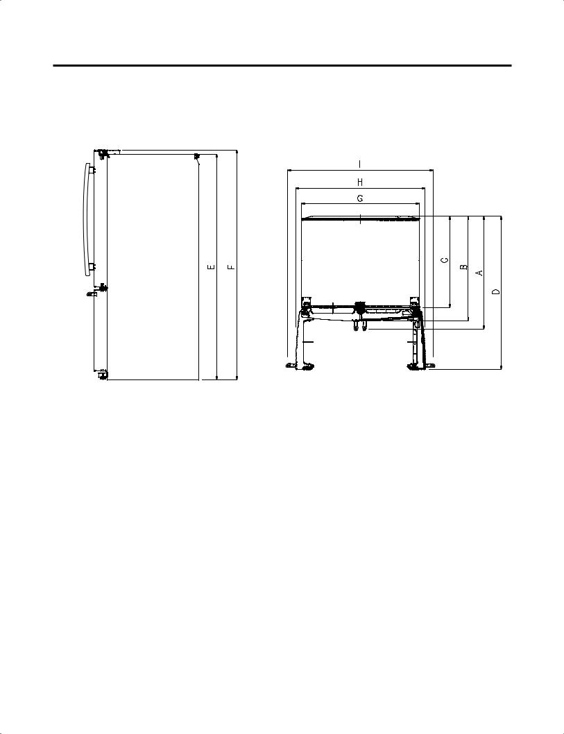
Description |
|
795.7105* |
|
|
|
Depth w/ Handles |
A |
35 3/8 in |
|
|
|
Depth w/ Handles |
B |
32 7/8 in |
|
|
|
Depth w/ o Door |
C |
29 in |
|
|
|
Depth (Total with Door Open) |
D |
47 5/8 in |
|
|
|
Height to Top of Case |
E |
68 3/8 in |
|
|
|
Height to Top of Door Hinge |
F |
69 3/4 in |
|
|
|
Width |
G |
35 3/4 in |
|
|
|
Width (door open 90 deg. w/o handle) |
H |
39 1/4 in |
Width (door open 90 deg. w/ handle) |
I |
44 1/4 in |
|
|
|
- 4 -
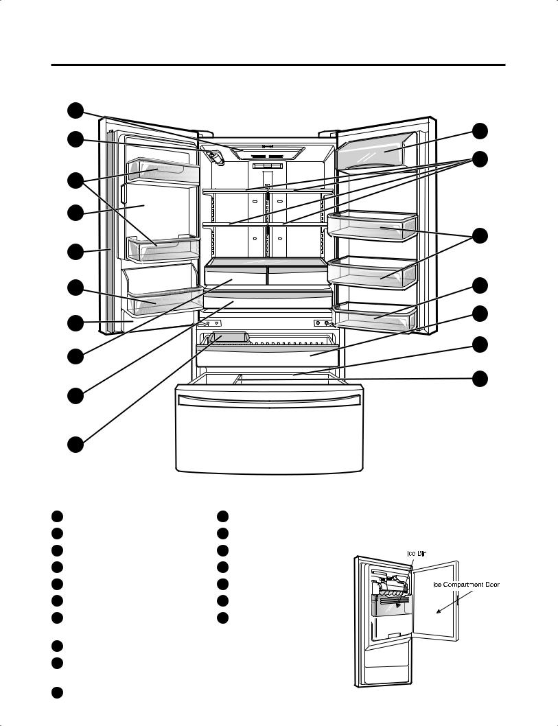
2. PARTS IDENTIFICATION
A |
|
B |
O |
|
|
|
F |
N |
|
G |
|
|
C |
Q |
|
D |
E |
P |
K |
|
|
H |
L |
|
|
|
M |
I |
|
J |
|
A |
K |
B |
L |
C |
M |
D |
N |
E |
O |
F |
P |
G |
Q |
H |
|
I |
Controlled |
Pantry Drawer |
|
J
- 5 -
3. DISASSEMBLY
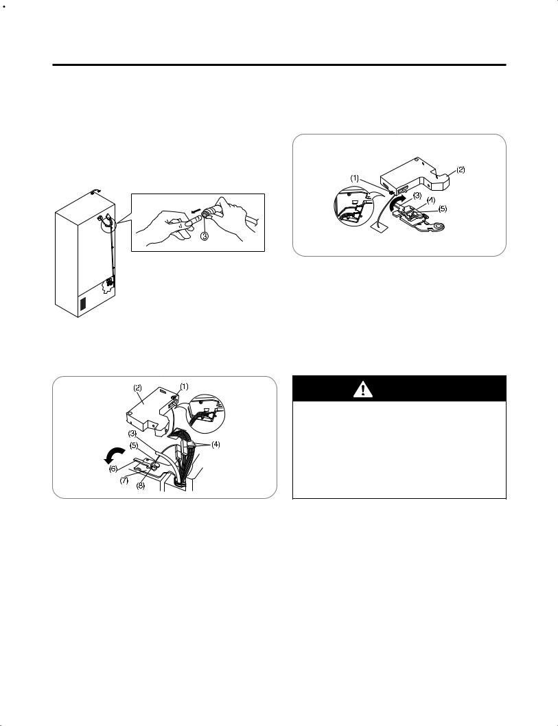
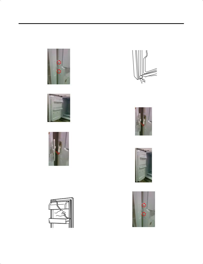
3-1 REMOVING AND REPLACING REFRIGERATOR DOORS
To remove the left refrigerator door:
Pull the water tube out of the fitting while pressing the release ring on the fitting.
When you pull out the tube, first you have to push the collet by opposite direction of arrow in the upper picture and tube pull out by direction of arrow.
 CAUTION: Before you begin, remove food and bins from the doors.
To remove the Right refrigerator door:
 Open the door. Remove the top hinge cover screw (1). Lift up the cover (2).
 Remove the cover.
Rotate the hinge lever (3) clockwise.
Lift the top hinge (4) free of the hinge lever latch (5). IMPORTANT: When lifting the hinge free of the latch, be careful that the door does not fall forward.
WARNING
Explosion Hazard
 Disconnect electrical supply to the refrigerator before installing. Failure to do so could result in death or serious injury.
 Do not put hands or feet or other objects into the air vents, base grille, or bottom of the refrigerator.
You may be injured or receive an electrical shock.  Be careful when you work with the hinge, base grille,
and stopper. You may be injured.
 Open the door. Remove the top hinge cover screw (1).
Use a flat-head screwdriver to pry back the hooks (not shown) on the front underside of the cover (2).
Lift up the cover.
Remove the cover. Pull out the tube (3). Disconnect all the wire harnesses (4). Remove the grounding screw(5)
Rotate hinge lever (6) counterclockwise.
Lift the top hinge (7) free of the hinge lever latch (8). IMPORTANT: When lifting the hinge free of the latch, be
careful that the door does not fall forward.
 Lift the door from the middle hinge pin and remove the door.
 Place the door, inside facing up, on a nonscratching surface.
- 6 -
3-2 DOOR
 Mullion Removal 1. Remove 2 screws.
2. Lift mullion up carefully.
3. Disconnect wire harness.
 Door Gasket Removal
1.Remove gasket
Pull gasket free from gasket channel on the four remaining sides of door.
 Door Gasket Replacement
1.Insert gasket into channel
Press gasket into channels on the four remaining sides of door.
 Mullion Replacement 1. Connect wire harness.
2.Insert mullion into channel.
Inserting mullion assy’ into bracket, door
3. Assemble 2 screws.
- 7 -
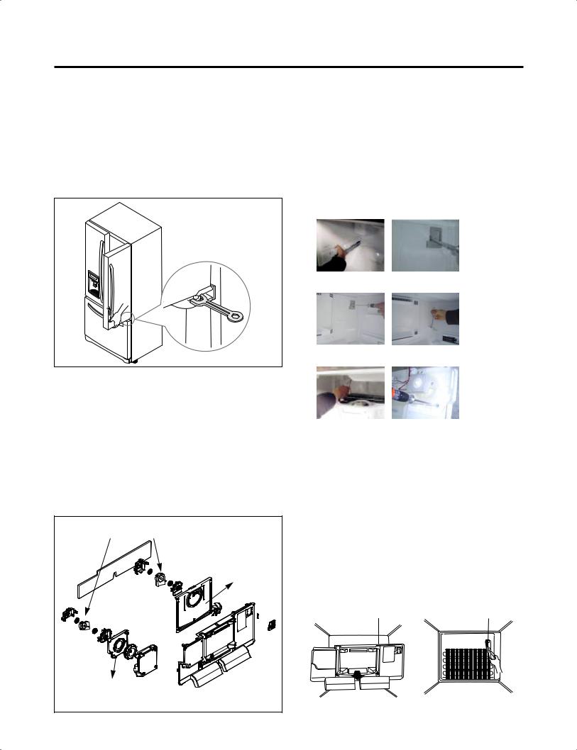
3-3 Door Alignment
If the space between your doors is uneven, follow the instructions below to align the doors:
Remove the Base Grillie. Turn the leveling legs (CCW) to raise or (CW) to lower the height of the front of the refrigerator by using flat blade screw driver or 11/32" wrench. Use the wrench (Included with the User Manual) to adjust the bolt in the door hinge to adjust the height. (CCW to raise or CW to lower the height.)
*Ice Fan Scroll Assembly Replacement
1)Remove the plastic guide for slides on left side by unscrewing phillips head screws.
2)Pull out the cover sensor to disassemble using tools shown in the figure.
3)Pull out the cover grille to disassemble using tools shown in the figure.
4)Put your hand into the inside of grille to disassemble shown in the figure.
5)Disconnect wire harness of the grille
6)Remove the scroll assembly by loosening all screws
3-4 FAN AND FAN MOTOR(EVAPORATOR)
1.Remove the freezer drawer. (If your refrigerator has an icemaker, remove the icemaker first)
2.Remove the plastic guide for slides on left side by unscrewing phillips head screws.
3.Remove the grille by removing four screws and pulling the grille forward.
4.Remove the Fan Motor assembly by loosening 3 screws and disassembling the shroud.
5.Pull out the fan and separate the Fan Motor and Bracket.
FAN MOTOR |
Shroud |
BRACKET |
MOTOR |
(1) |
(2) |
(3) |
(4) |
(5) |
(6) |
3-5 DEFROST CONTROL ASSEMBLY
Defrost Control assembly consists of Defrost Sensor and FUSE-M.
The Defrost Sensor works to defrost automatically. It is attached to the metal side of the Evaporator and senses its temperature. At 46F(8°C), it turns the Defrost Heater off. Fuse-M is a safety device for preventing over-heating of the Heater when defrosting.
1.Pull out the grille assembly. (Figure 1)
2.Separate the connector with the Defrost Control assembly and replace the Defrost Control assembly after cutting the Tie Wrap. (Figure 2)
GRILLE ASSEMBLY |
DEFROST-CONTROL |
|
ASSEMBLY |
||
|
Figure 1 |
Figure 2 |
- 8 -
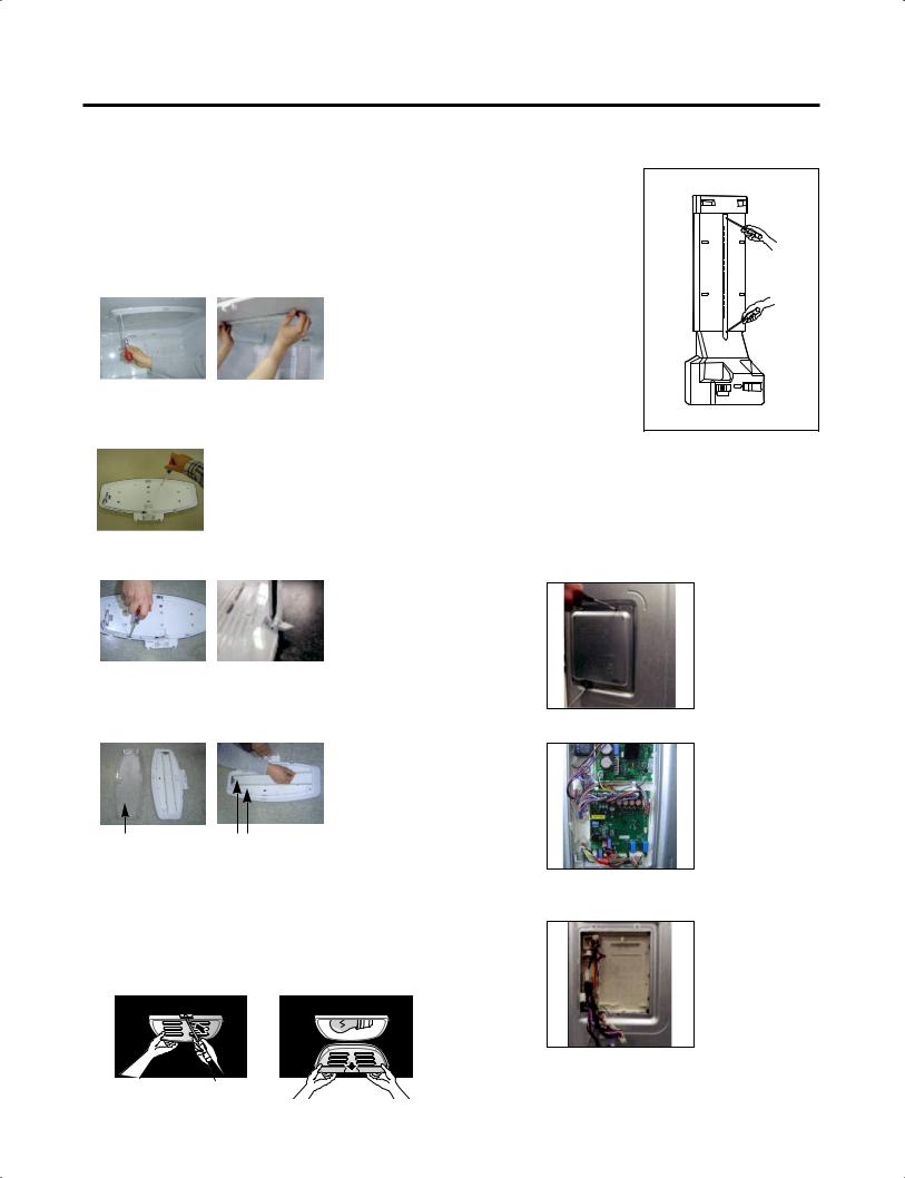
3-6 LAMP
Unplug Refrigerator, or disconnect power at the circuit breaker.
If necessary, remove top shelf or shelves.
3-6-1 Refrigerator Compartment Lamp
1)Release 2 screws.
2)Hold both ends with your both hands and pull it downward to remove it.
3)To remove the case lamp and cover lamp, release another 2 screws as following picture.
3)Use a flat blade screwdriver as shown below to remove the cover lamp.
4)To remove the LED Assembly, open the Hook part to pull it out as shown in the following picture.
 Case, lamp
Cover, lamp LED, Assembly
3-6-2 Freezer Compartment Lamp
1.Unplug refrigerator power cord form outlet.
2.Remove screw with driver.
3.Grasp the cover Lamp,pull the cover downward.
3-7 MULTI DUCT
1.Remove the upper and lower Caps by using a flat screwdriver, and
remove 2 screws. (Figure 3)
2.Disconnect the lead wire on the bottom position.
Figure 3
3-8 MAIN PWB
 WARNING : Unplug the refrigerator before removing the control board.
1) Loosen the 3 screws on the PWB cover.
2) Remove the PWB cover
3)Disconnect wire harness and replace the main PWB in the reverse order of removal.
- 9 -
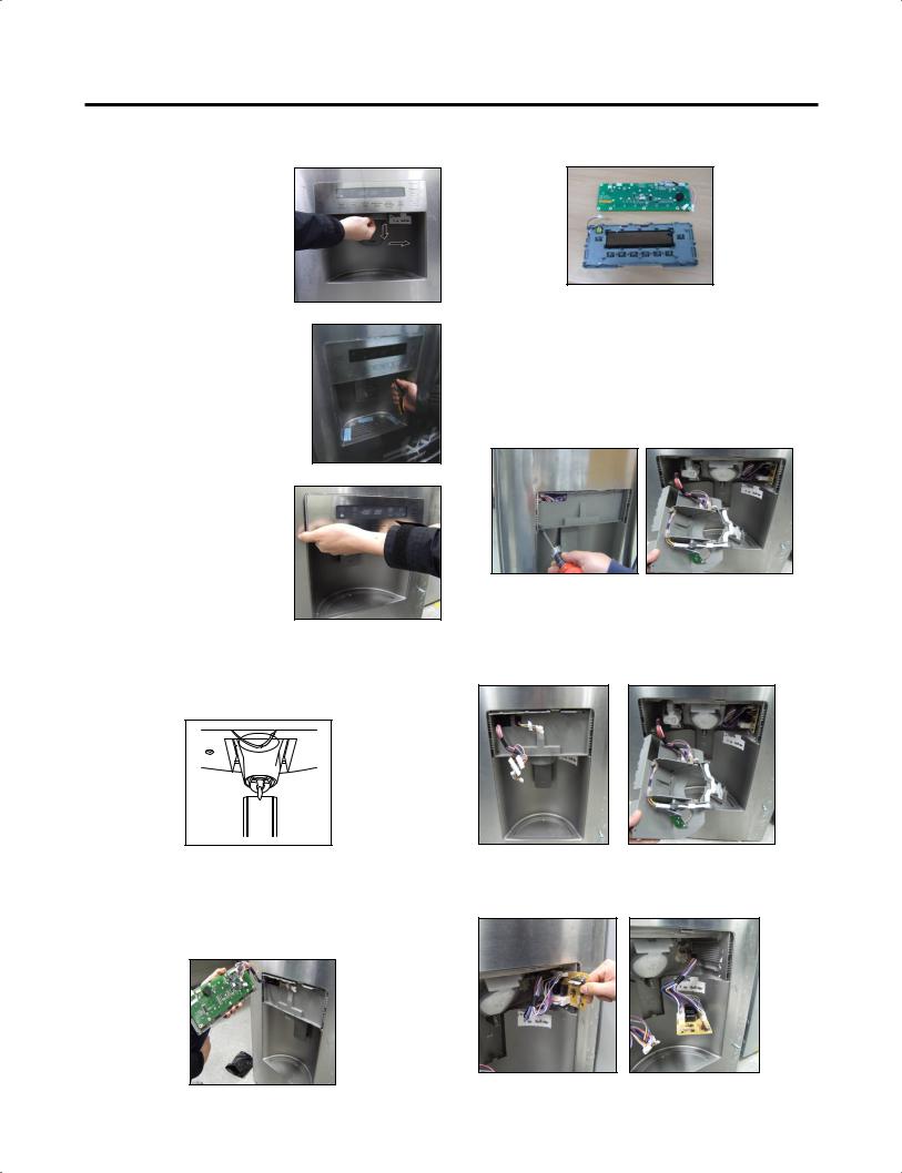
3-9 DISPENSER
1)Disconnect funnel by pulling down and forward.
3) Use a flat blade screwdriver at bottom side hole of the “Cover Assembly dispenser” to detach hooks of the bottom side.
3)Hold the bottom side of the “Cover Assembly, dispenser” as shown in the picture, and pull and remove it. The cover dispenser is attached with a hook.
2) Follow the steps in the pictures.
3-11 FUNNEL REPLACEMENT
1)Pull up and out on the dispenser cover to remove.
2)Remove 2 screws.
3)Disconnect the wire harness.
4)Replace in reverse order.
 CAUTION: When replacing the dispenser cover in the reverse order of removal, be careful that the lead wire does not come out and the water tube is not pinched by the dispenser cover, as shown in the picture below.
3-10 DISPLAY PWB REPLACEMENT
1)Pull up and out on the dispenser cover to remove and replace PWB with dispenser cover.
3-12 SUB PWB FOR WORKING DISPENSER
1) Loosen the screw on the sub PWB.
2)Pull the sub PWB down.
3)Disconnect the wire harness and replace the sub PWB in the reverse order of removal.
- 10 -
3-13 CAP DUCT REPLACEMENT
1)Pull up and out on the dispenser cover to remove.
2)Disconnect the wire harness.
3)Remove the funnel.
4)Replace in reverse order.
3-14 CAP DUCT MOTOR REPLACEMENT
1) Separate the Housing of the Cap Duct Motor.
2) Unscrew 3 screws to disassemble the motor.
5) Contract the Housing.
3-15 ICE CORNER DOOR REPLACEMENT
1)Loosen the front screw as shown in the picture.
2)Lift up the hinge with one hand.
3)Pull out the Ice Corner Door with the other hand.
3)When replacing to a new Motor, always check position of the Duct Door and Link to install the Motor.
 Duct Door

 Link
Link
Cap Duct Motor
NG Position
4) Assemble on the screws.
- 11 -
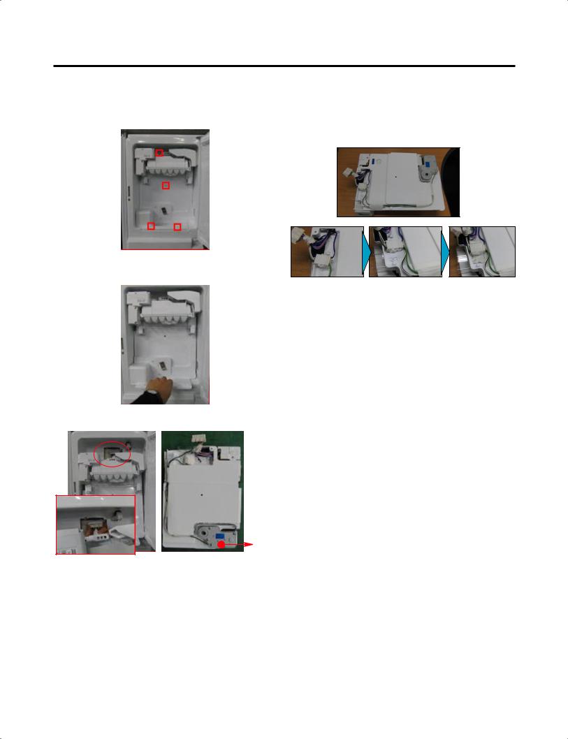
3-16 Icemaker replacement
1)Remove the stainless screws marked in the picture below.
2)Grasp the bottom of motor cover assembly and pull it out slowly.
3) Disconnect wire harness from wall of compartment.
door
 CAUTION : Make sure that the wire harness shown below is positioned properly in the clips on the back of the cover, and taped in place. If this harness is loose it will not allow the motor housung assembly to fit flush to the door liner.
- 12 -
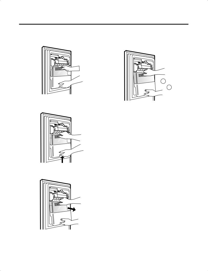
3-17 HOW TO REMOVE A ICE BIN |
3-18 HOW TO INSERT A ICE BIN |
1) Grip the handles, as shown in the picture. |
1) Insert the Ice Bin, slightly tilting it to avoid touching the |
|
Icemaker. (Especially, Ice-Detecting Sensor) |

2) Lift the lower part slightly.
3) Take the Ice Bin out slowly.
- 13 -
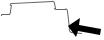
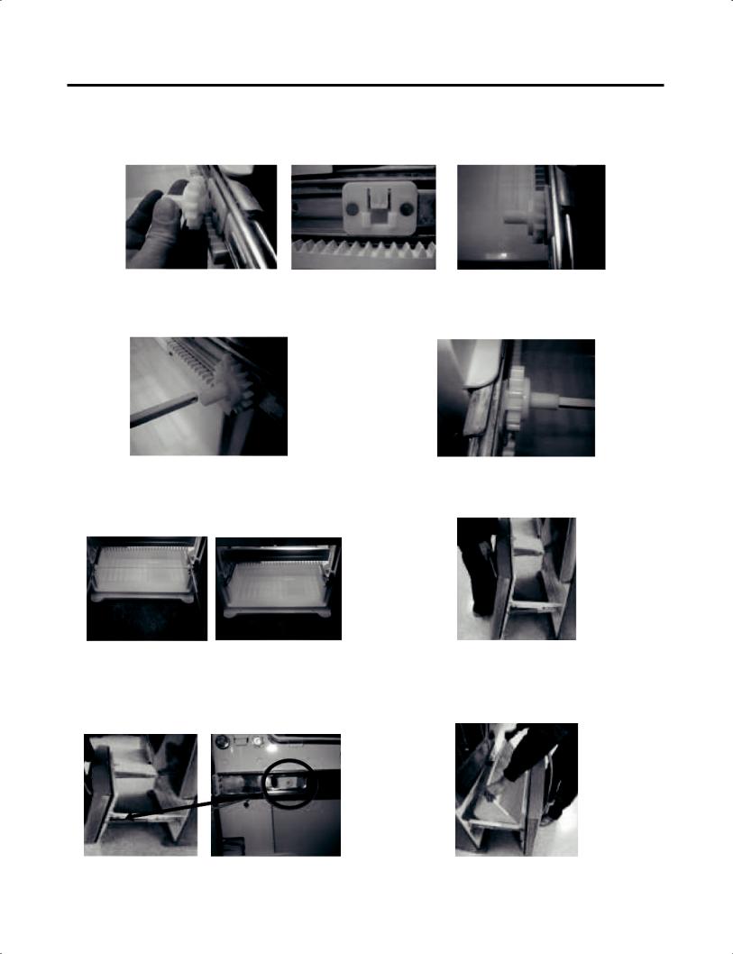
3-19 HOW TO REMOVE AND REINSTALL THE PULLOUT DRAWER
3-19-1 Follow Steps to Remove
Step 1) Open the freezer door. |
Step 2) Remove the lower basket. |
Step 3) Remove the two screws from the guide rails (one from each side).
Step 4) Lift the freezer door up to unhook it from the rail support and remove.
Pull both rails to full extension.
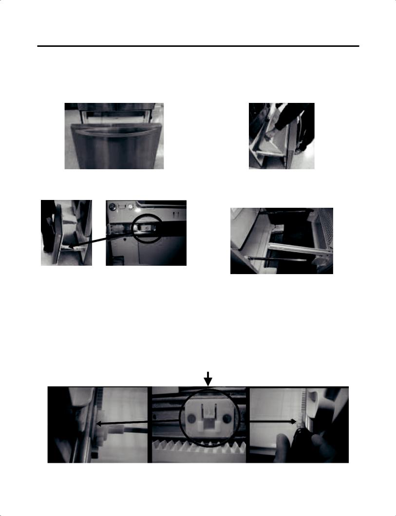
Step 5) First: Remove the gear from the left side first by releasing the tab behind the gear, place a screwdriver between the gear and the tab and pull up on the gear.
Second: Remove the center rail.
Third: Remove the gear from the right side by following the same steps for the left side.
NOTE: THIS TAB MUST BE PUSHED IN TO RELEASE THE GEAR.
- 14 -
3-19-2 Follow Steps to Reinstall
Step 1) Reinstall the right side gear into the clip.
Step 2) Insert the rail into the right side gear. Gears do not need to be perpendicular to each other.
Step 4) The rail system will align itself by pushing the rails all the way into the freezer section.
Pull the rails back out to full extension.
Step 6) Reinstall the two screws into the guide rails (one from each side).
Step 3) Insert the rail into the left side gear, and insert the gear into the clip.
Step 5) Reinstall the freezer door by inserting the rail tabs into the guide rail.
Step 7) Reinstall the lower basket, and close the freezer door.
- 15 -
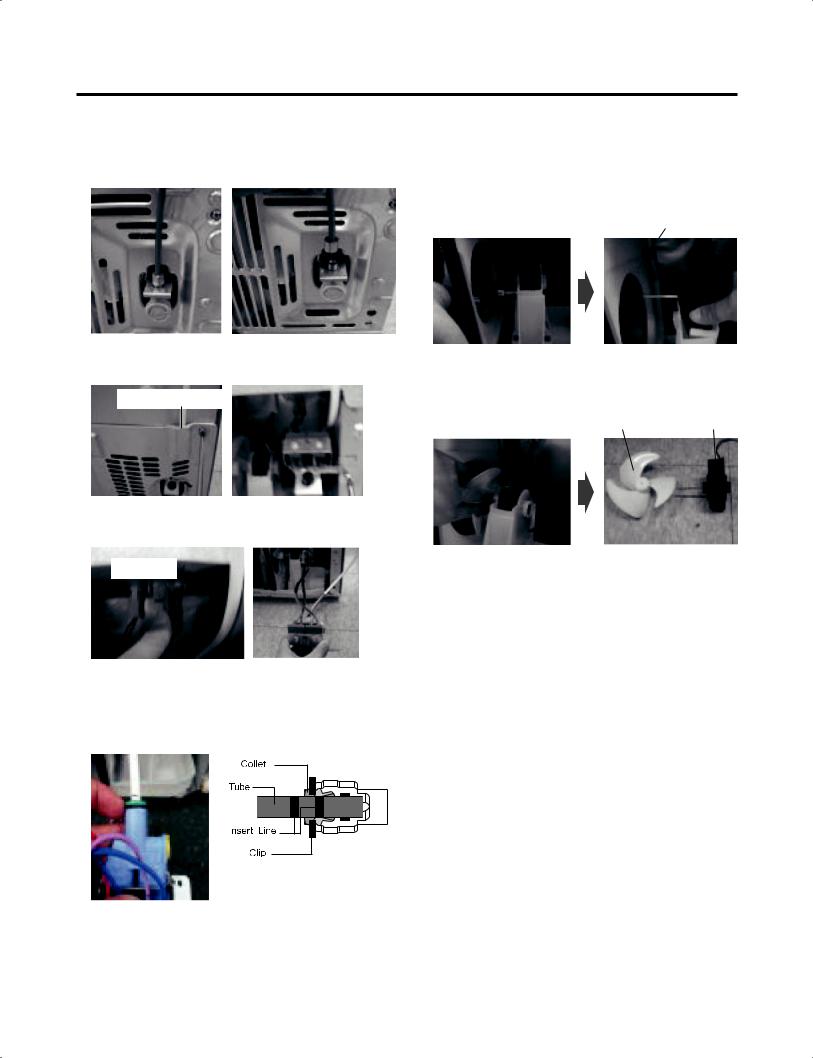
3-20 WATER VALVE DISASSEMBLY METHOD
1)Turn off the water. Then separate the water line from the valve.
2) Separate the Mechanical Cover and Valve Screw.
Mechanical Cover
3) Separate the housing and pull out the valve.
Housing
4)Befrore disconnecting the water lines, place a towel under the water valve to catch any water that may come out. Pull out the clip and press the collet to separte the water line from the valve.
3-21 FAN AND FAN MOTOR DISASSEMBLY METHOD
1)Using a short screwdriver, loosen one SCREW in DRAIN PIPE ASSEMBLY and one connected to the MOTOR COVER.
MOTOR COVER
2)Pull and separate the FAN ASSEMBLY and MOTOR turning counterclockwise based on the MOTOR SHAFT.
FAN ASSEMBLY MOTOR
The assembly is in the reverse order of the disassembly and take special care for the following details.
1.Be careful not to bend the tube during assembly.
2.Press the WATER DISPENSER button until water pours out and check for leakage in the CONNECTOR TUBE (It differs by the water pressure but usually takes about 2 minutes until water pours out.)
- 16 -
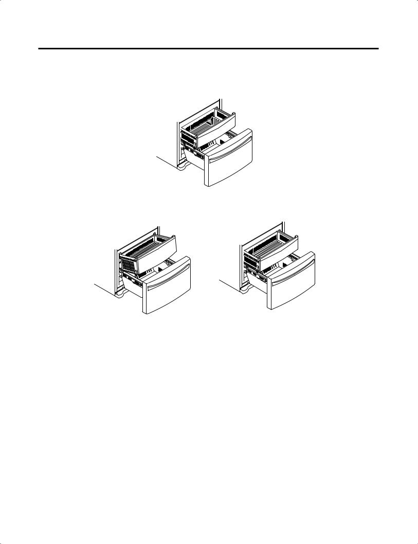
3-22 PULL OUT DRAWER
To remove, pull the drawer out to full extension.
Lift the front of the drawer up, then pull it straight out.
To install, slightly tilt up the front and insert the drawer into the frame and push it back into place.
- 17 -
4. ADJUSTMENT
4-1 COMPRESSOR
4-1-1 Role
The compressor intakes low temperature and low pressure gas from the evaporator of the refrigerator and compresses this gas to high-temperature and high-pressure gas. It then delivers the gas to the condenser.
4-1-2 Note for Usage
(1)Be careful not to allow over-voltage and over-current.
(2)Do not drop or handle carelessly.
(3)Keep away from any liquid.
If liquid such as oil or water enters the Cover PTC Compressor may fail due to breakdown of their insulating capabilities.
(4)Always use the Parts designed for the compressor and make sure it is properly attached to the compressor. Parts may appear physically identical but could have different electrical ratings. Replace parts by part number and model number. Use only approved substitute parts.
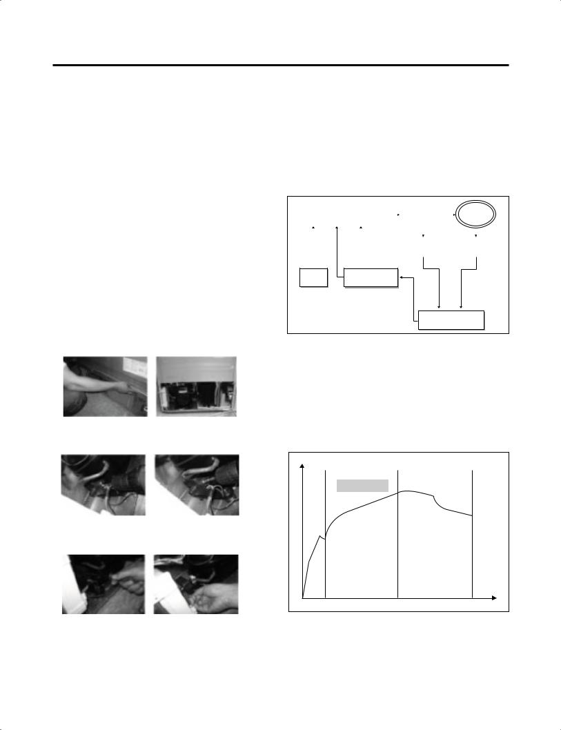
4-1-3 REMOVE THE COVER PTC
4-2 Introduction of E-Linear Compressor
 E-Linear compressor is run by mechanical part design through automatically varying the cooling power. The main parts consist of compressor and Sub PCB which controls the compressor. PCB authorizes constant voltage and constant frequency to the compressor and protects it.
4-2-1 Control of Compressor Block Diagram
|
|
|
PWM |
|
|
Linear |
||||
Compressor Controller |
Signal |
|
Inverter |
|
|
|||||
Frequ |
|
|
Comp |
|||||||
|
|
|
|
|
|
|
||||
|
|
|
-ency |
|
|
|
|
|
|
|
|
|
|
|
|
|
|
|
|
||
|
|
|
|
|
|
|
|
|
|
|
|
|
|
|
|
|
|
|
|
|
|
|
|
|
|
|
DC link |
|
|
Vcap Voltage |
||
|
|
|
|
|
Voltage |
|
|
|||
|
|
|
|
|
|
|||||
|
|
|
|
|
|
|
|
|
||
|
|
|
|
|
|
|
|
|
|
|
Main |
Counter elec- |
Micom |
tromotive force |
Calculate counter electromotive force
Control Block Diagram of Compressor
(1) Remove the Cover Back M/C
(2) Loosen two screws on comp base
(3)Use a L-shaped flap tooll to pry off the cover
(4)Assembly in reverse order of disassembly
4-2-2 Compressor operating pattern
 Drive half stroke after turning on initial power for 30 seconds. Then, slowly increase stroke and reach target input. Once reaching the target input, input naturally changes according to refrigerator load without any special control.
Comp. input |
Interval 1) Half stroke interval - after initial running, stay at the initial value for 30 seconds
Interval 2) Running interval - Increase at every 0.8 till it reaches the target input; it takes about 3’ 45”
Interval 3) CVCF interval - Run by target voltage and main operating frequency and the input naturally changes according to refrigerator load
- 18 -

5. CIRCUIT DIAGRAM
PWB ASSEMBLY,
 SMART BUZZER
PWB
ASSEMBLY,
AMBIENT LED
- 19 -
6. TROUBLESHOOTING
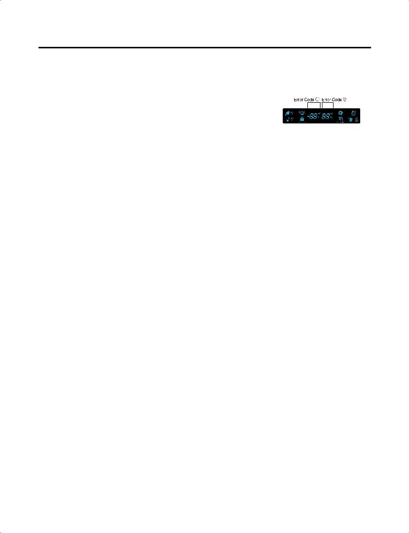
6-1. Error Code Summary
 WARNING: When you check the Resistance values, be sure to turn off the power.
And wait for the voltage-discharge sufficiently.
NOTE) 3 hours before the error : Press the Ultra ICE button and Freezer button simultaneously 3 hours after the error : All errors, except for "Er rt", "Er SS", "Er IS(except for Icing sensor)", "Er gF", "Er It" error, are displayed.
"Er IS" which is displayed without input of user is the error of Icing Sensor.
|
Error Detection |
Error Display |
|
|
||
NO |
|
|
Error Generation Factors |
Remark |
||
Category |
Freezer |
Freezer |
||||
|
|
|
||||
|
|
Temperature |
Temperature |
|
|
|
1 |
Normality |
|
|
None |
Normal operation of Display |
|
|
|
|
|
|
|
|
2 |
Freezer Sensor |
Er |
FS |
Short or Disconnection |
|
|
Error |
of Freezer Sensor |
|
||||
|
|
|
|
|||
|
|
|
|
|
|
|
3 |
Refrigerator |
Er |
rS |
Short or Disconnection |
|
|
Sensor Error |
of Refrigerator Sensor |
|
||||
|
|
|
|
|||
4 |
Defrosting |
Er |
dS |
Short or Disconnection |
|
|
Sensor Error |
of Defrosting Sensor |
|
||||
|
|
|
|
|||
|
|
|
|
|
Check each sensor and its |
|
|
|
|
|
Short or disconnection of |
||
5 |
Icing Sensor |
Er |
IS |
the sensor about Ice maker |
connector. |
|
Error |
(Icing sensor, Ice maker |
|
||||
|
|
|
|
|||
|
|
|
|
sensor) |
|
|
6 |
Pantry sensor |
Er |
SS |
Short or Disconnection |
|
|
error |
of Pantry Sensor |
|
||||
|
|
|
|
|
|
|
7 |
Room Temp |
Er |
rt |
Short or Disconnectoin of |
|
|
Sensor Error |
Room temp.sensor |
|
||||
|
|
|
|
|
|
|
|
|
|
|
|
When the ice does not drop |
|
8 |
Ice maker kit |
Er |
It |
Other Electric system error |
even when the I/M Test S/W |
|
such as moter, gear, Hall IC, |
is pressed |
|||||
defect |
||||||
|
|
|
operation circuit within I/M kit |
(same as model applied |
||
|
|
|
|
|||
|
|
|
|
|
Twisting Ice Maker before) |
|
|
|
|
|
|
|
|
9 |
Flow |
Er |
gF |
Error of flow meter or water |
Error of flow meter or water |
|
Meter(Sensor) |
input or low water pressure or |
|||||
input or low water pressure |
||||||
|
Defect |
|
|
flow meter connection |
||
|
|
|
|
|||
|
|
|
|
|
|
|
|
|
|
|
Even though it is passed |
Temperature Fuse |
|
10 |
Poor Defrosting |
Er |
dH |
1 hour since then Defrosting, |
Disconnection, Heater |
|
if Defrosting sensor is not |
disconnection, DRAIN Jam, |
|||||
|
|
|
|
|||
|
|
|
|
over 46°F(8°C), it is caused |
Poor Relay for Heater |
|
|
|
|
|
|
|
|
|
Abnormality of |
|
|
It is caused when feedback |
|
|
11 |
Er |
IF |
signal isn’t over 65 seconds |
Poor BLDC Motor connection, |
||
BLDC FAN Motor |
||||||
during BLDC FAN motor |
DRIVE IC, and TR |
|||||
|
for Ice Making |
|
|
|||
|
|
|
operating |
|
||
|
|
|
|
|
||
|
|
|
|
|
|
|
|
Abnormality of |
|
|
It is caused when feedback |
|
|
12 |
Er |
FF |
signal isn’t over 65 seconds |
Poor BLDC Motor connection, |
||
BLDC FAN Motor |
during BLDC FAN motor |
DRIVE IC, and TR |
||||
|
for Freezer |
|
|
operating |
|
|
|
|
|
|
|
|
|
|
Abnormality of |
|
|
It is caused when feedback |
|
|
13 |
BLDC FAN |
Er |
rF |
signal isn’t over 65 seconds |
Poor BLDC Motor connection, |
|
|
MOTOR For |
|
|
during BLDC FAN motor |
DRIVE IC, and TR |
|
|
Refrigerator |
|
|
operating |
|
|
|
Abnormality of |
|
|
It is caused when feedback |
|
|
14 |
BLDC FAN Motor |
Er |
CF |
signal isn’t over 65 seconds |
Poor BLDC Motor connection, |
|
for Mechanic |
during BLDC FAN motor |
DRIVE IC, and TR |
||||
|
|
|
||||
|
Room |
|
|
operating |
|
|
|
|
|
|
|
|
|
|
|
|
|
Communication Error |
Poor Communication |
|
|
Communication |
|
|
connection,Poor TR of |
||
15 |
Er |
CO |
between Micom of Main PCB |
Transmitter and Receiver |
||
Error |
||||||
|
|
|
and Display Micom |
Tx/Rx between display and |
||
|
|
|
|
|||
|
|
|
|
|
main board. |
|
|
|
|
|
|
|
|
- 20 -
7. PCB Picture
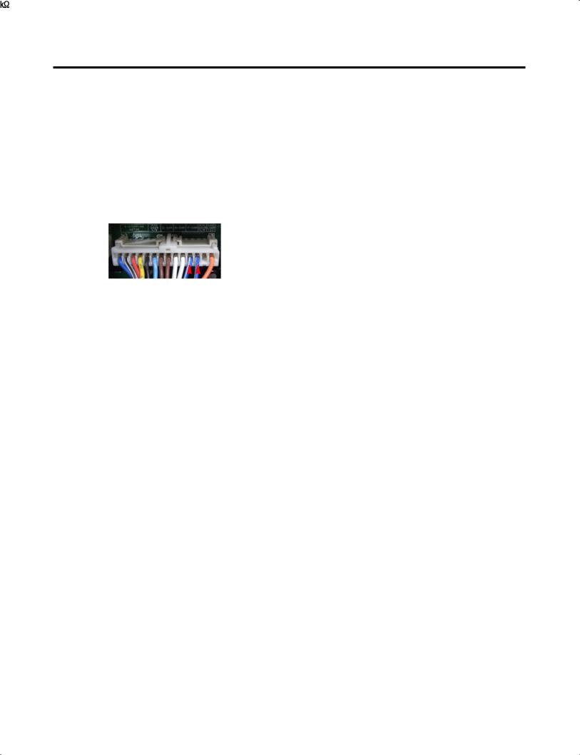
7-1 Main PCB
P/No & MFG |
|
|
|
|
Picture |
||
|
|
|
|
|
|
|
|
|
CON1 |
|
|
CON8 |
|||
|
|
|
|
|
|
|
|
|
|
|
|
|
|
|
CON6 |
EBR65002701 |
|
|
|
|
|
|
CON5 |
(2010.02~) |
CON2 |
|
|
|
|||
|
|
|
|
||||
|
|
|
|
|
|
|
CON4 |
|
CON3 |
|
|
|
|||
|
|
|
|
|
|
|
CON10 |
|
|
|
|
|
|
|
|
|
|
|
CON203 |
|
|
|
|
EBR64173902 |
|
|
|
|
|
|
|
|
|
|
|
|
|
|
|
|
|
|
|
|
|
|
|
(2010.02~) |
|
|
|
|
|
|
|
Refer to 48Page |
|
|
|
|
|
|
|
|
|
|
|
|
|
||
|
|
|
|
|
|
|
|
|
|
|
|
|
|
|
|
|
|
|
|
|
|||
|
CON201 |
|
CON2 |
||||
|
|
|
|
|
|
|
|
|
|
|
|
|
|
|
|
- 21 -

7-2 Display PCB & Sub PCB
P/No |
Picture |
Display PCB EBR65768601 (2010.02~)
CON104 |
CON102 CON101 |
||||
|
|
|
|||
|
|
|
|
|
|
|
|
|
|
|
|
CON1
Sub PCB
EBR60070704
(2010.02~)
CON2
- 22 -
8. Troubleshooting With Error Display
8-1 Freezer Sensor Error (Er FS)
No |
Checking flow |
|
|
|
Result & SVC Action |
||||||||
|
|
|
|
|
|
|
|
|
|
|
|
|
|
1 |
Check for a loose connection. |
|
|
|
|
|
|
|
|
|
|
||
|
|
|
|
|
|
|
|
|
|
|
|
|
|
2 |
Check the Blue/White to |
|
|
|
|
|
|
|
|
|
|
||
|
|
Result |
|
|
|
SVC Action |
|
||||||
|
Blue/White. |
|
|
|
|
|
|
||||||
|
|
|
|
|
0 |
|
Short |
|
|
Change the sensor |
|
||
|
|
|
|
|
|
|
|
|
|
|
|
|
|
|
|
|
|
|
|
|
Open |
|
Replace the refrigerator |
|
|||
|
|
|
|
|
|
|
|
|
|
|
|
|
|
|
|
|
|
|
|
|
Normal |
|
|
Check the Temp and |
|
||
|
|
|
|
|
|
|
|
|
resistance (Table-1) |
|
|||
|
|
|
|
|
|
|
|
|
|
|
|
||
|
|
|
|
|
|
|
|
|
|
|
|
||
|
|
|
|
|
|
<Temperature table-1> |
|||||||
|
|
|
|
|
|
|
|||||||
|
<CON6> |
|
|
||||||||||
|
|
|
|
|
|
(1) To (2) |
|
Result |
|
|
|||
|
|
|
|
|
|
|
|
|
|
|
|
|
|
|
|
|
|
|
|
-22°F |
°C |
|
40 |
|
|
||
|
|
|
|
|
|
|
|
|
|
|
|
||
|
|
|
|
|
|
-13°F |
°C |
|
30 |
|
|
||
|
|
|
|
|
|
|
|
|
|
|
|
||
|
|
|
|
|
|
-4°F |
°C |
|
23 |
|
|
||
|
|
|
|
|
|
|
|
|
|
|
|
||
|
|
|
|
|
|
5°F |
°C |
|
17 |
|
|
||
|
|
|
|
|
|
|
|
|
|
|
|
||
|
|
|
|
|
|
14°F |
°C |
|
13 |
|
|
||
|
|
|
|
|
|
|
|
|
|
|
|
||
|
|
|
|
|
|
23°F |
°C |
|
10 |
|
|
||
|
|
|
|
|
|
|
|
|
|
|
|
||
|
|
|
|
|
|
32°F |
°C |
|
8 |
|
|
||
|
|
|
|
|
|
|
|
|
|
|
|
||
|
|
|
|
|
The sensor is determined by |
||||||||
|
|
|
|
|
the temperature. |
|
|
|
|
||||
|
|
|
|
|
For example, 23 |
indicates -4°F. |
|||||||
|
|
|
|
|
|
|
|
|
|
|
|
|
|
- 23 -

8-2 Refrigerator Sensor Error (Er rS)
No |
Checking flow |
|
|
Result & SVC Action |
|
||||||||
|
|
|
|
|
|
|
|
|
|
|
|
|
|
1 |
Check for a loose connection. |
|
|
|
|
|
|
|
|
|
|
||
|
|
|
|
|
|
|
|
|
|
|
|
|
|
2 |
Check the White to White. |
|
|
|
|
|
|
|
|
|
|
||
|
Result |
|
|
|
SVC Action |
|
|||||||
|
|
|
|
|
|
|
|
|
|
||||
|
|
|
|
|
0 |
|
Short |
|
|
Change the sensor |
|
||
|
|
|
|
|
|
|
|
|
|
|
|
|
|
|
|
|
|
|
|
|
Open |
|
Replace the refrigerator |
|
|||
|
|
|
|
|
|
|
|
|
|
|
|
|
|
|
|
|
|
|
|
|
Normal |
|
|
Check the Temp and |
|
||
|
|
|
|
|
|
|
|
|
resistance (Table-2) |
|
|||
|
|
|
|
|
|
|
|
|
|
|
|
||
|
|
|
|
|
|
|
|
|
|
|
|
|
|
|
<CON6> |
|
|
|
<Temperature table-2> |
|
|||||||
|
|
|
|
|
|
|
|
||||||
|
|
|
|
|
|
|
|
|
|
|
|||
|
|
|
|
|
|
(1) To (2) |
|
Result |
|
|
|||
|
|
|
|
|
|
|
|
|
|
|
|
||
|
|
|
|
|
|
23°F |
°C |
|
38 |
|
|
||
|
|
|
|
|
|
|
|
|
|
|
|
||
|
|
|
|
|
|
32°F |
°C |
|
30 |
|
|
||
|
|
|
|
|
|
|
|
|
|
|
|
||
|
|
|
|
|
|
41°F |
°C |
|
24 |
|
|
||
|
|
|
|
|
|
|
|
|
|
|
|
||
|
|
|
|
|
|
50°F |
°C |
|
19.5 |
|
|
||
|
|
|
|
|
|
|
|
|
|
|
|
||
|
|
|
|
|
|
59°F |
°C |
|
16 |
|
|
||
|
|
|
|
|
|
|
|
|
|
||||
|
|
|
|
|
The sensor is determined by |
|
|||||||
|
|
|
|
|
the temperature. |
|
|
|
|
||||
|
|
|
|
|
For example, 30 |
indicates 32°F. |
|
||||||
|
|
|
|
|
|
|
|
|
|
|
|
|
|
- 24 -
 Loading...