


ASSEMBLY INSTRUCTIONS
for:
Drop-Down
Ladder Rack
40853
11261 Trade Center Drive Rancho Cordova, CA 95742
(916) 638-8703 (800) 343-7486

40853 Parts List
Ladder Pan Stiffener
Item -030
Qty 1
Torque Tube Assembly
Item -029
Qty 1
Crank Assembly
Item -026
Qty 1
Cross Bows Assembly
Item -001
Qty 2
Gutter Mount Foot
Item -041 QTY 4
Hold Down Assembly
Item -007
QTY 2
Gutter Clamps
Item -045
QTY 4 Ford
Gutter Clamps
Item -044
QTY 4 Chevy
Hinge Assembly
Item -006
QTY 2
Ladder Pan
Assembly
Item -005
QTY 2
Load Lock Plate
Item -070 QTY 2
Hold Down Plate
Item -008
QTY 2
E-6000
E-6000
QTY 1
1

Tools Needed
8' Tape Measure
7/16 Socket
1/2 Socket
9/16 Socket
1/2 End Wrench
9/16 End Wrench
Small Hammer
40853 HARDWARE
LIST
Hardware Pack
Motion Pack
Qty 1 -Damper
Qty 1 -Spring
Qty 2 -Links
Component Pack
Qty 4
Wheel
Item -002
Qty 2
Axle
Item-003
(a)
Qty 9 3/8-16 x 1 Carriage Bolt
(d)
Qty 6 3/8-16 x 5/8 Hex Bolt
(c)
Qty 8 3/8-16 Nylock Nut
(b)
Qty 10 3/8 Flat Washer
(e)
Qty 6 3/8 Lock Washer
(f)
Qty 4 5/16 x 3/4 Carriage Bolt
(s)
Qty 4 5/16-18 x 3/4 Hex Bolt
(k)
Qty 34 5/16 Flat Washer
Qty 4
Nylon Washer
Item -038
Qty 1
Ladder Stop
Item -009
(p)
Qty 4 5/16 Lock Washer
(h)
Qty 22 5/16 Nylock Nut
(v)
Qty 4 5/16 x 2 Hex Bolt
(u)
Qty 4 5/16 x 1 1/4 Carriage Bolt
2

Step 1
Attach each Gutter Mount Foot Item -041 to Cross Bow Item -001 using 2 x 3/8" x 1"
carriage bolt, flat washer and lock nut.
Use location "A" for Ford or "B" for Chevy.
Tighten almost all the way, but leave slightly loose to allow for adjustment later.
Limited access to these nuts makes final tightening difficult, so minimize.
Bow
"A"
3/8 Locknut(c)
3/8 Flat Washer(b)
3/8x1 Carriage
Bolt(a)
Foot
"B"
3

Step 2
If you are installing a driver side Drop-Down Mechanism 40863 or Clamp & Lock
Mechanism 40813, you will not use item -070. Disregard this Step 2.
Item -070 to both bows on the driver side only.
Item-070
Load/Lock
Plate
5/16 Flat
Washer(k)
If not, attach
5/16 x 3/4
Carriage Bolt(f)
5/16 Locknut(h)
DETAIL A
SCALE 1 : 3
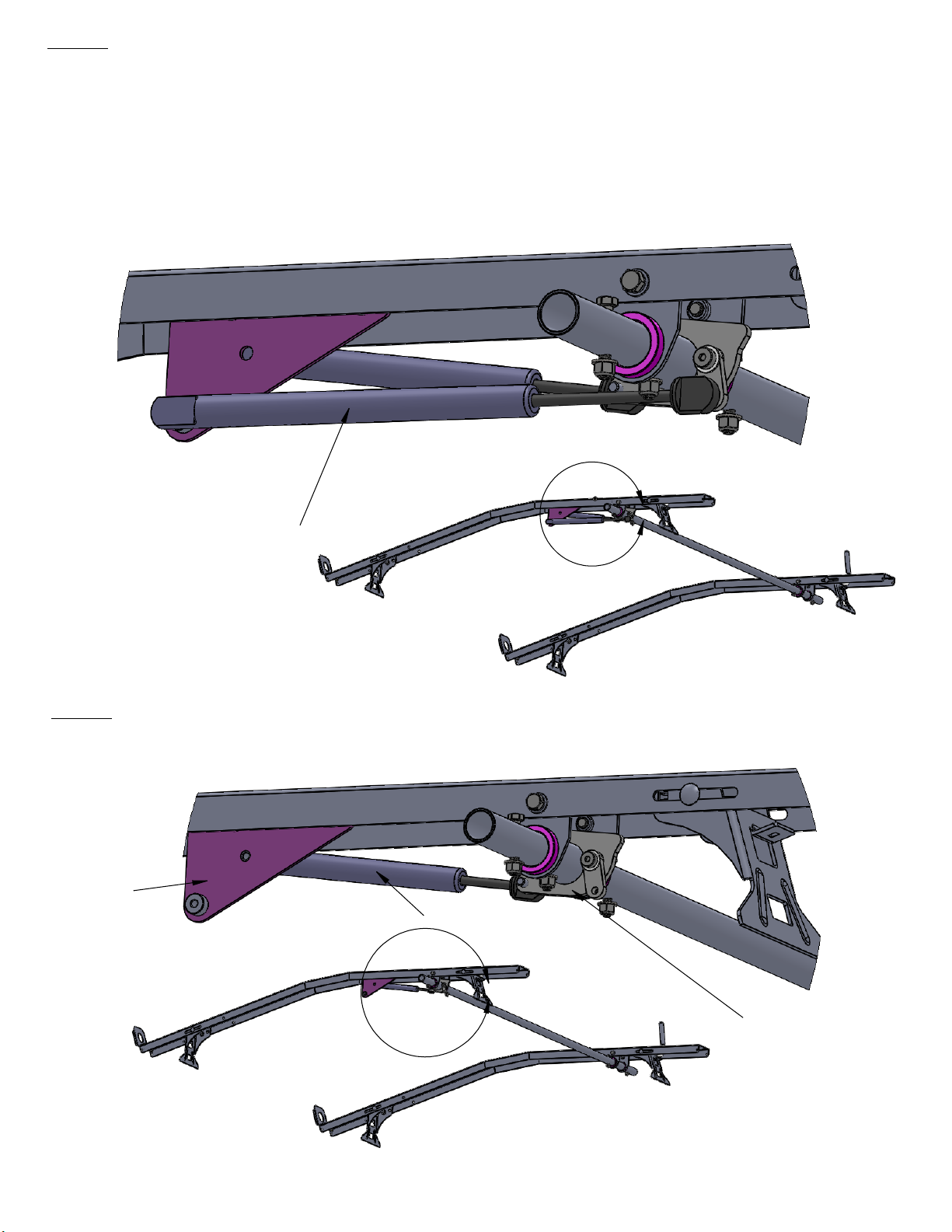
IMPORTANT:
If you are installing a driver side Drop-Down Mechanism 40863, open box, find
Item -048 Spring/Dampener Mount and attach it to the FRONT Cross Bow NOW
using 2 x 3/8 x 1 carriage bolt, flat washer and lock nut. See Diagram below.
Item-001
Van Front
Item-041
Item-070
Item -048
For 40863
Item-048
A
Van Rear
4

Step 3
We recommend building the rack on a workbench, and then using 3 friends or a hoist to
position the completed rack on the floor of the van. If this is not possible, then you will have
to build the rack on the roof of the van as set forth below.
Place the rear bow (this is the one with the triangular Spring/Damper Mount Item -048
attached) on top of the van with the Kargo Master decal facing the back of the van.
Position the rear bow about 16" forward of the back of the van as shown below.
If you are installing a driver side Drop-Down Mechanism 40863, open box, find Item -048
Spring/Dampener Mount and attach it to the FRONT Cross Bow NOW using 2 x 3/8 x 1
carriage bolt, flat washer and lock nut.
Place the front bow on top of the van with the Kargo Master decal facing the front of the
van. Position the front bow so that there is about 67 5/8" between the bows as shown below.
87.5
67.62
16.0
5

Step 4
Before attaching the Torque Tube Assembly Item-002, check to ensure that the link
rotates easily by hand. See diagram below.
Position the U Bracket that goes around the Cam Assembly up inside the flanges of
the REAR bow.
Attach the U Brackets to the front and back bow using 4 x 3/8" x 5/8"
carriage bolts, flat washers and lock nuts as shown below.
3/8 lock washer(e)
3/8Flat washer(b)
3/8x5/8 Bolt(d)
Item-048
Spring/Damper
Mount
Item-001
Bow
U Bracket
Item-029
Torque Tube Assy.
Cam Assembly
DETAIL B
SCALE 1 : 4
Link
B
6
Step 5
Study the diagram below. This step must be done correctly the first time.
The Dampener
and Spring are easy to attach to the factory mounted ball studs, but they are hell
to get off.
THE LONGER BLACK TUBE IS THE SPRING. THE SPRING ATTACHES TO THE BALL
STUD ON THE LINK.
The diagram below is a view of the REAR Bow from the REAR of the van. The Torque
Tube Assembly is on the passenger side.
Press the Spring onto the CORRECT (Link) factory mounted ball studs as shown below.
Spring (long)
D
Step 6
Press the Dampener onto the CORRECT (not the Link) ball studs as shown below.
Item-048
Dampener (short)
C
Cam Assy.
Gold Zinc Plated
7

Step 7
Locate the Component Pack in your bolt kit. Insert Axle Item-003 through the holes at
the end of the FRONT and REAR Bow as shown below. Put a Nylon Washer Item-038
and a Wheel Item-002 on each end of the Axle.
Item-038
(Nylon Washer)
Item-003(Axle)
DETAIL F
SCALE 1 : 5
Item-002(Wheel)
DETAIL G
SCALE 1 : 5
G
F
8

Step 8
Now attach the 2 x Ladder Pan Assemblies Item-005. Hold the Pan at about a 45
degree angle, with the arms hanging downward. There is a slot on each side of
the pan. Position the Pan slots over the wheels, and lower the pan down until
resting on the wheels. Be sure not to knock the nylon wheel caps off when lowering
the Pan. See diagram below.
Item-005
Ladder Pan Assy.
Slot for Wheels
DETAIL H
SCALE 1 : 3
Wheels with Nylon Caps
H
9

Roll the Ladder Pan toward the center of the van. Guide the Arms so that the
semicircular cutouts at the ends wrap around the Torque Tube. With this
accomplished, lower the Pan down so that it is on the Bow. See Detail I
below. Rotate the Tube to align the holes in the Arms with the holes in the
Tube.
DETAIL I
Ladder Pan
Assy.
Torque Tube
5/16 x 2 Bolt
Handle Assy.
Arm
Torque Tube
Black
Bushing
5/16 flat
Washer
5/16 Nylock
Nut
J
I
10

Step 9
Build the Handle Assembly as shown below. Coat the swaged end of the Handle
Assembly Item-026 with a thick layer of E6000 sealant. Insert the Handle into the Tube.
Align the holes in the Arms, tube, and Handle. Attach the Arms and Handle to the
Tube using 2 x 5/16" x 2" hex bolts, flat washers and lock nuts. See Detail J below and
Detail I above.
Coat entire swaged surface with E6000
Detail J
11

Step 10
40853 is designed to carry and secure either an extension or a step ladder. If the
end-user intends to carry an extension ladder, attach Hinge Assembly Item-006 to
the REAR BOW at location "A". If the end-user intends to carry a step ladder, attach
Hinge Assembly to the REAR BOW at location "B". The Hinge Assembly is always
attached to the FRONT BOW at location "A". If the type of ladder to be carried is
unknown, default to the extension ladder set up. The end-user can relocate the
Hinge Assembly in the field if necessary. There is a label on the rack and separate
instruction sheet attached to the rack in a plastic pouch. See Diagrams below.
Slide the front and rear Hinge Assemblies onto the Ladder Pans at the correct
location, either "A" or "B". Attach to the "A" location (where there is a threaded stud)
using 4 x 5/16" flat washers, and lock nuts. See Detail M below. Attach to the "B"
location (where there is a threaded press nut inside the Bow) using 4 x 5/16" x 3/4"
bolts, lock wahsers and flat washers. These fasteners are attached to the REAR Bow
at the factory. See Detail L below.
Hinge Assy.
Item-006
Location "B"
Step Ladder
Location "A"
Extension
Ladder
DETAIL L
SCALE 1 : 4
VAN REAR
5/16x3/4
Bolt
5/16Lock
Washer
5/16 Flat
Washer
5/16 Flat
Washer
L
M
5/16 Nylock
Nut
12
VAN FRONT

Step 11
The Link Rods come from the factory with the ball studs attached. If the Hinge
Assembly is attached in Location "A", insert the Link Rod threaded ball studs through
the holes in the Hinge Assembly and the Ladder Pan Arms as shown in Detail P
below. Secure using 2 x 5/16" flat washer and lock nuts. If the Hinge Assembly is
attached in Location "B" (REAR Bow step ladder set-up), insert the Link Rod threaded
ball studs through the holes in the Hinge Assembly and the Ladder Pan Arms as
shown in Detail N below. Secure using 2 x 5/16" flat washer and lock nuts.
REAR BOW
Location "A"
Extension Ladder
5/16 Nylock Nut
5/16 Flat Washer
5/16 Nylock Nut
5/16 Flat Washer
Location "B"
Step Ladder
FRONT BOW
Location "A"
Threaded Boss
DETAIL N
SCALE 1 : 8
DETAIL P
SCALE 1 : 8
N
P
13

Step 12
Attach each Ladder Hold Down Assembly Item-007 to the Hinge Assembly using 1 x
3/8" x 5/8" hex bolt, lock washer and flat washer as shown below.
Tighten only snug as
the Hold Down and the J clip must be adjusted to the ladder by the end-user in the
field. There is a label on the rack and separate instruction sheet attached to the rack in
a plastic pouch.
Ladder Hold Down
(Item-007)
3/8 Lock
Washer
3/8 x 5/8
Bolt
3/8 Flat
Washer
J Clip
T
14

Step 13
Attach each End Plate Item-008 and the Pan Stiffener Item-030 as shown below using
2 x 5/16" x 3/4" bolts, lock washers and flat washers.
There is a LEFT and RIGHT End
Plate. Be sure to locate properly. The ladder retainer pins go on the outboard side of
the Plates. Tighten only snug as the End Plates must be adjusted to the ladder by the
end-user in the field. There is a label on the rack and separate instruction sheet
attached to the rack in a plastic pouch.
Ladder Stop
Pan Stiffener
Item-030
Item -009
Right End Plate
Item-008
5/16 Flat
Washer
5/16x3/4
Bolt
5/16 Lock
Washer
Step 14
Attach Ladder Stop Item -009 to Front Bow (or maybe Rear Bow if you are left handed)
using 3/8 x 1 carriage bolt. See diagram below.
15
R
Ladder Stop
Item -009

Step 15
If you have built the rack on a workbench, position it on top of the van now. Make
certain that each Gutter Mount Foot Item-041 is sitting down firmly on the metal
rain gutter. Chevy vans have a bead of mastic on the outboard side of the rain
gutter. The Foot should be positioned inboard of the mastic. Your rack includes
4 x Chevy Gutter Clamps Item -044 and 4 x Ford Gutter Clamps Item -045. See
diagram below. Select the appropriate Clamps for your vehicle.
Insert a Gutter Clamp through each Foot as shown below. Attach a Clamp to
each Foot using 5/16" x 1 1/4" carriage bolt, flat washer, and lock nut. Before
tightening fully, make certain that the Clamp has good purchase on the bottom of
the rain gutter. Tighten the nut to a torque rating of about 150 inch pounds, or until
the rain gutter of the clamp or the tongue of the Foot begin to deform.
Do not
overtighten.
Ford Item -045
Chevy Item -044
(u)
(k)
(h)
THAT'S IT, YOUR DROP-DOWN LADDER RACK INSTALLATION IS COMPLETE.
DON'T FORGET TO REMIND THE END-USER TO MAKE FIELD ADJUSTMENTS AS NECESSARY
TO PROPERLY SECURE THE LADDER.
16
 Loading...