

Page 1

ASSEMBLY INSTRUCTIONS
for :
PRO-II
SERVICE BODY
12_1.1
Parts: 70020 & 70023
(916) 638-8703
®
(800) 343-7486
• 11261- G Trade Center Drive • Rancho Cordova, CA 95742 •
Page 2
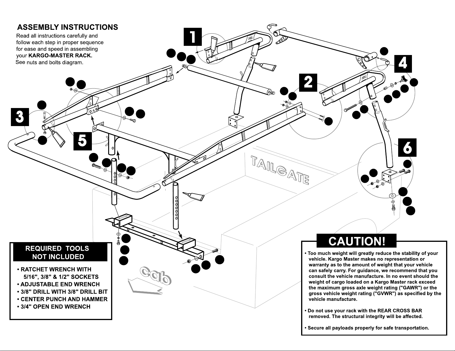
PRO II - SERVICE BODY
3
G
I
1
P
O
H
I
H
H
A
G
O
O
P
5
P
O
O
G
G
O
O
P
M
2
L
U
K
Q
J
4
W
E
U
N
G
H
H
I
G
O
O
P
U
R
V
H
O
P
O
P
H
R
V
U
12_1.1
Page 3
H
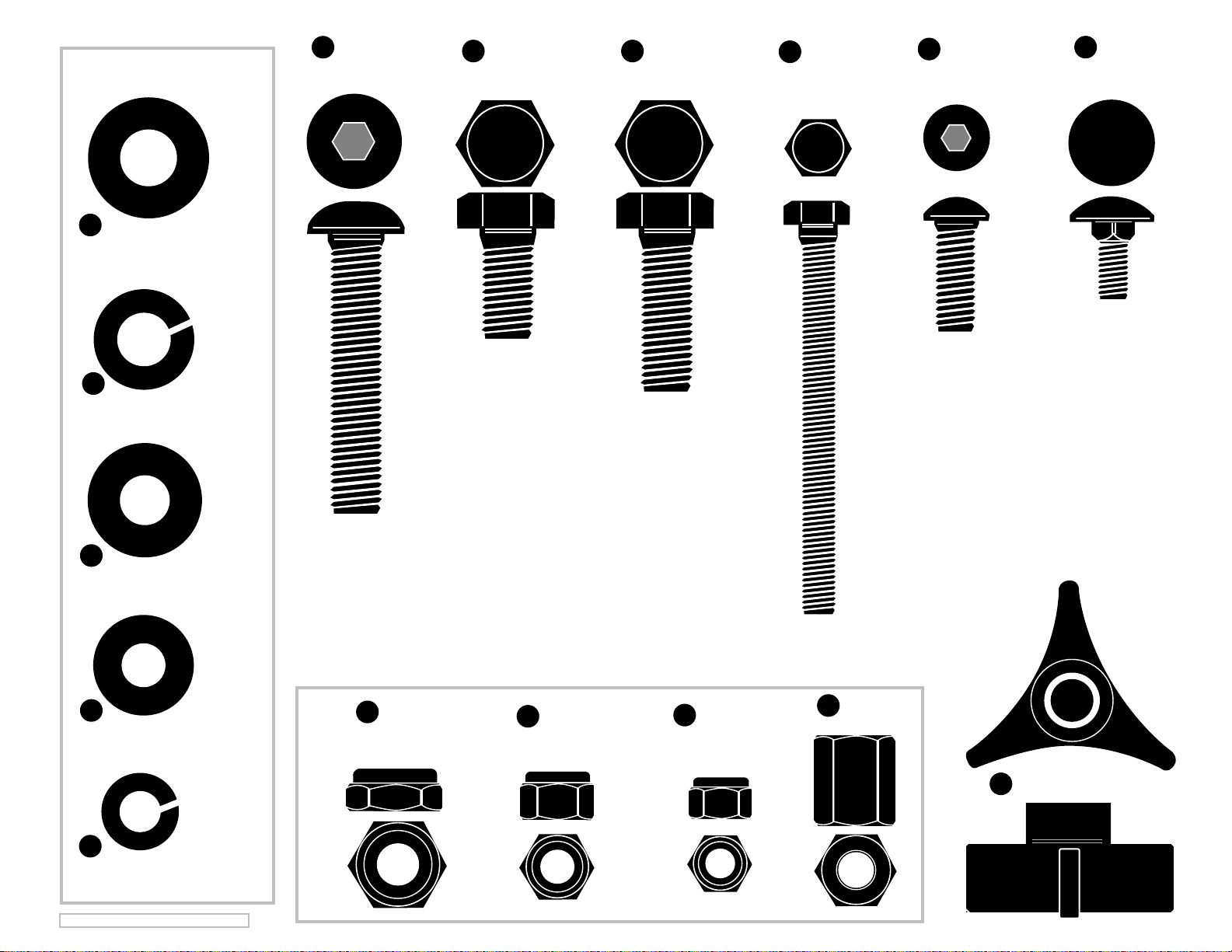
(20 ea.) 1/2" SAE Flat Washer
O
(6 ea.) 1/2" Lock Washer
G
(4 ea.)
1/2" x 2 1/2"
Button Head Bolt
P
1/2" x 1"
Hex Bolt
(6 ea.)
(4 ea.)
A
1/2" x 1 1/2"
Hex Bolt
(2 ea.)
K
3/8" x 3 1/2"
Tap Bolt
(6 ea.)
V
3/8" x 1"
Button Head
(4 ea.)
Q
5/16" x 3/4"
Carriage Bolt
U
(14 ea.) 3/8" SAE Flat Washer
L
(4 ea.) 5/16" Flat Washer
E
(2 ea.) 3/8" Lock Washer
©2012 KARGO MASTER --SrvBody 12_1.1
I
(8 ea.)
1/2" Jam Nut
R
(8 ea.)
3/8" Lock Nut
M
(4 ea.)
5/16" Lock Nut
N
(2 ea.)
3/8" Coupling Nut
W
(2 ea.)
Plastic Knob
Page 4
SRV-BODY 12_1.1
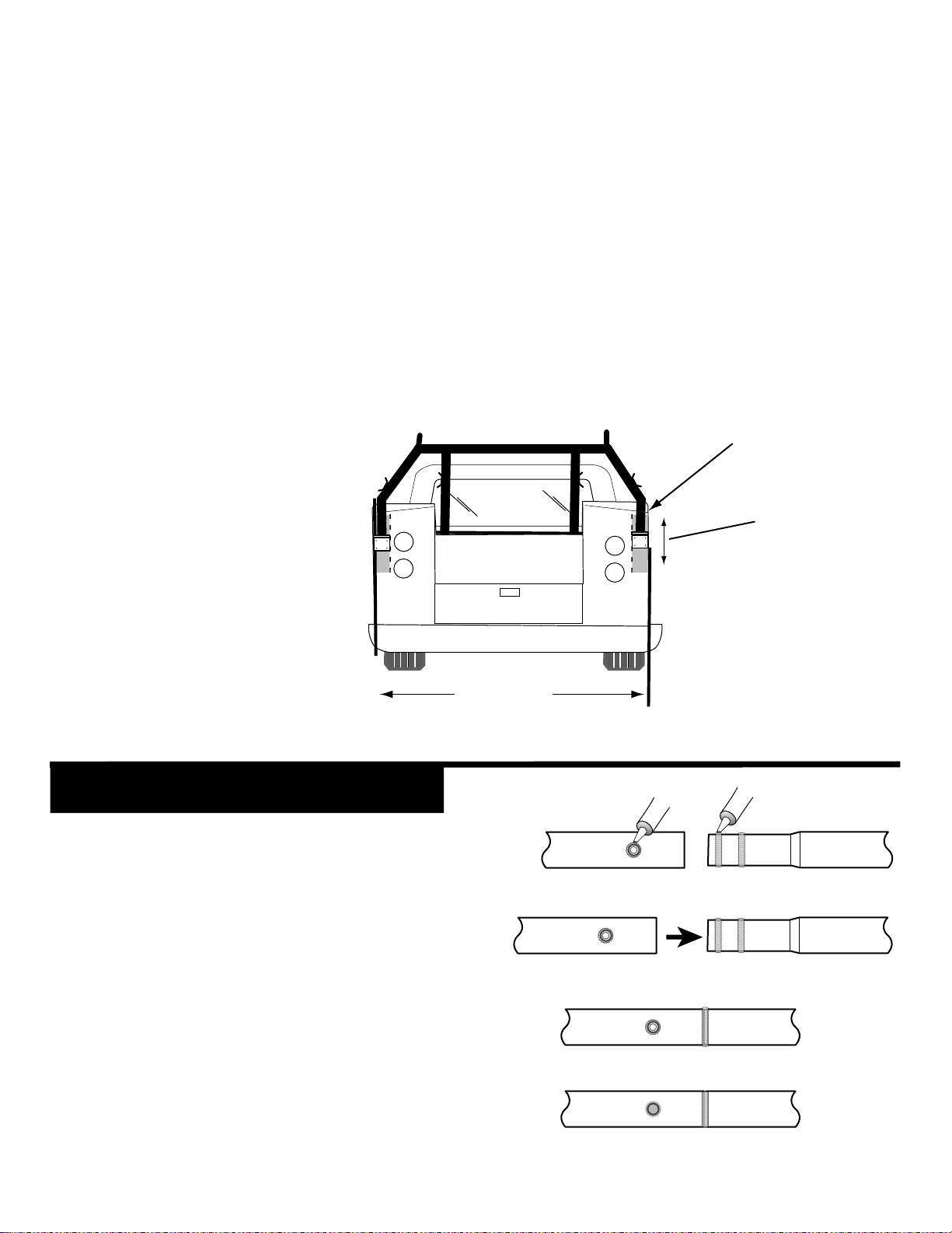
BEFORE YOU BEGIN, PLEASE VERIFY THAT THIS RACK WILL FIT YOUR SERVICE BODY.
#1- Side Channel kit 78010 will fit an 8ft. body mounted on an extended cab chassis. Side Channel kit 78000
will fit an 8ft. body mounted on a standard cab chassis. Side Channel kit 79010 will fit a 9ft. body mounted on an
extended cab chassis, or an 11 ft. body mounted on a standard cab chassis. Side Channel kit 79000 will fit a 9ft.
body mounted on a standard cab chassis.
#2- The "bulkhead" is the panel that is the front of the service body. Measure the distance from the top of the
bulkhead to the top of the truck's cab. This distance should be in the range of 15" to 22".
#3- Standard mounting is on rear panel. Check to ensure that the rear panel of the service body is free of
taillights or other obstructions (inside or out) in the area where the rear legs of the rack bolt to the body.
Consult sketch below:
NOTE: If it is not possible to attach
the included rear leg mounts to your
service body back panel because the
panel is plastic or because the tail
lights or box lock handle are in the
way, please see OPTIONAL
MOUNTING METHODS on the back
page. These options require
accessory mount kit #70060
purchased separately.
GOOP APPLICATION
LBS.
77.5" - 79"
Swaged joint & holes
GOOP
GOOP
REAR MOUNTS
ATTACHING AREA
7"
VARIABLE HEIGHT
ADJUSTMENT
AREA
Apply a healthy air tight bead of goop
around every swaged joint as shown, to
prevent moisture from leaking into and out
of the joint. If this is not done properly, the
inside surface of the tubes can rust and
rusty water can leak out. Maintain this
joint seal throughout the life of your rack.
Smooth goop at swaged joint & holes
Page 5
STEP 1
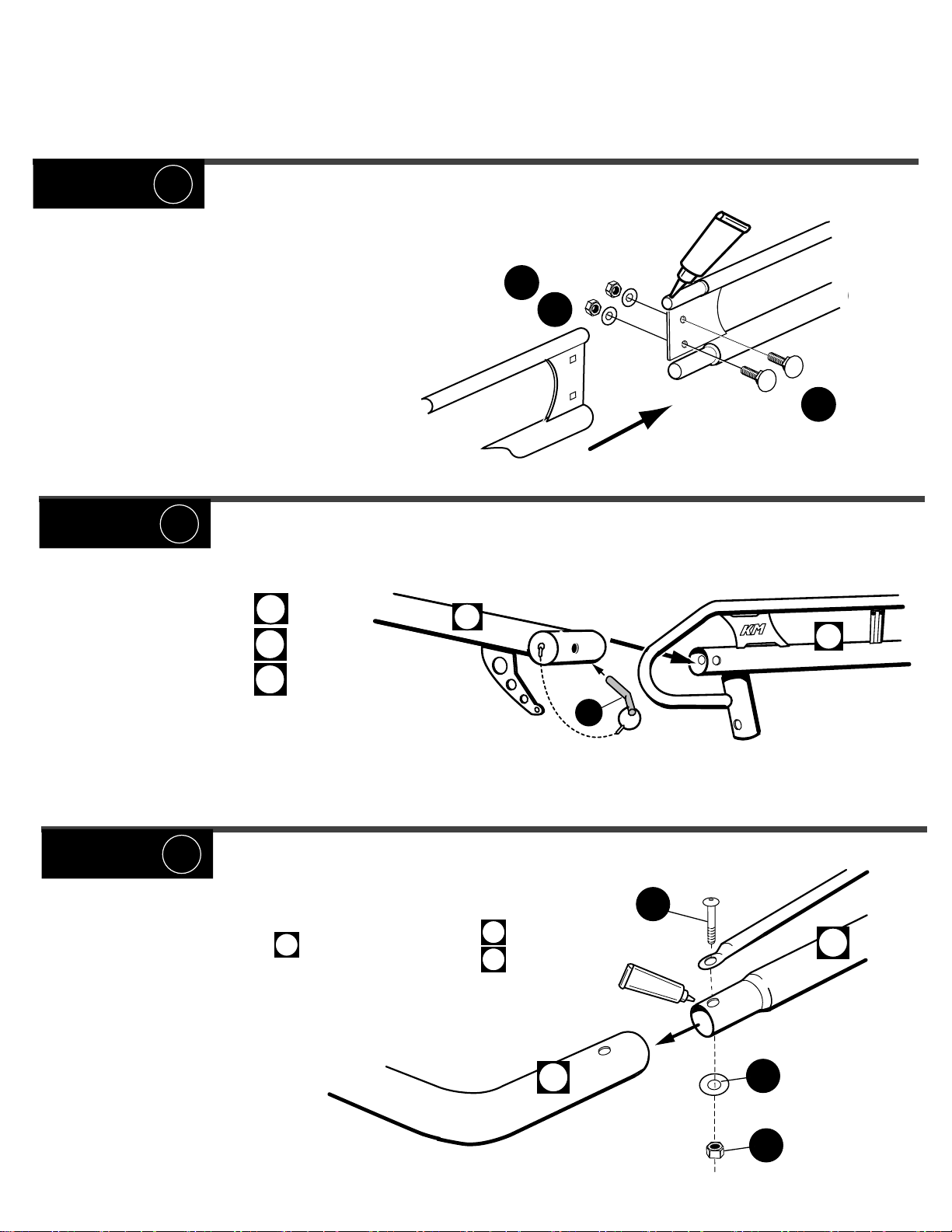
#1 = Cover entire swedge joints with GOOP and
join FRONT and REAR side channels together.
Be sure the connecting plates overlap and bolt
together with bolts Q, washers L and lock nuts M.
STEP 2
M
L
SRV-BODY 12_1.1
P
O
O
G
Q
#1= Slide REAR BAR on to
REAR SIDE BEAMS
#2= Fully insert LOCK PINS J
completely to the bend of the pin.
D
04
06
D
J
STEP 3
#1= Cover entire swedged joint surfaces with GOOP,
Slide FRONT CROSS BAR , into FRONT SIDE BEAMS
#2= BOLT TOGETHER using G, H & I.
A
The allen wrench is included
in the package.REAR SIDE BEAMS
03
05
06
J
G
03
GOOP
A
H
I
Page 6
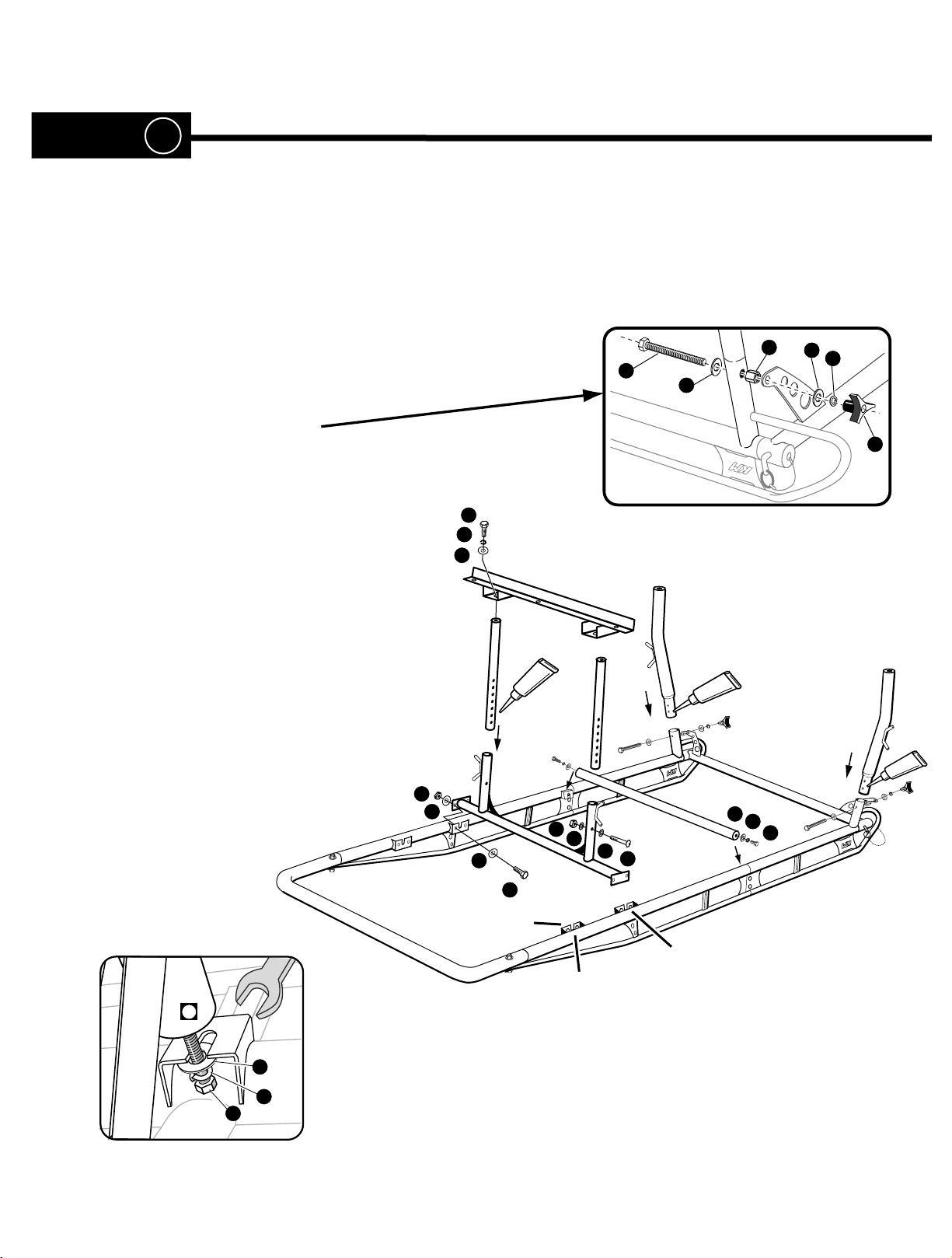
STEP 4
#1= Turn partially assembled rack upside down as shown.
Cover entire swedged joint surfaces with GOOP,
then insert the swedged end of each REAR leg ,
rope hooks facing outward, into the short tubes projecting
from the bottom of the SIDE BEAMS.
#2= Bolt REAR LEGS and
REAR BAR BRACE (as shown)
SRV-BODY 12_1.1
N
K
U
U
E
W
#3= After determining your service body length,
attach FRONT CROSS BAR
to appropreate “U Clips” with bolts
flat washer
NOTE: 11 ft “U-Clip will be on the 79010 model only.
Start bolt P, with lock washer O, flat washer H,
#4=
H and jam nut I.
A,
into ends of 4th CROSS BAR, position onto rack
then with an open end 3/4" wrench, snug bolts
on each side of the rack.
44
//
33
B
I
H
P
O
H
H
“U Clips”
GOOP
I
H
H
G
A
GOOP
GOOP
H
O
P
9 ft
11 ft
(79010 model only)
H
O
P
Page 7
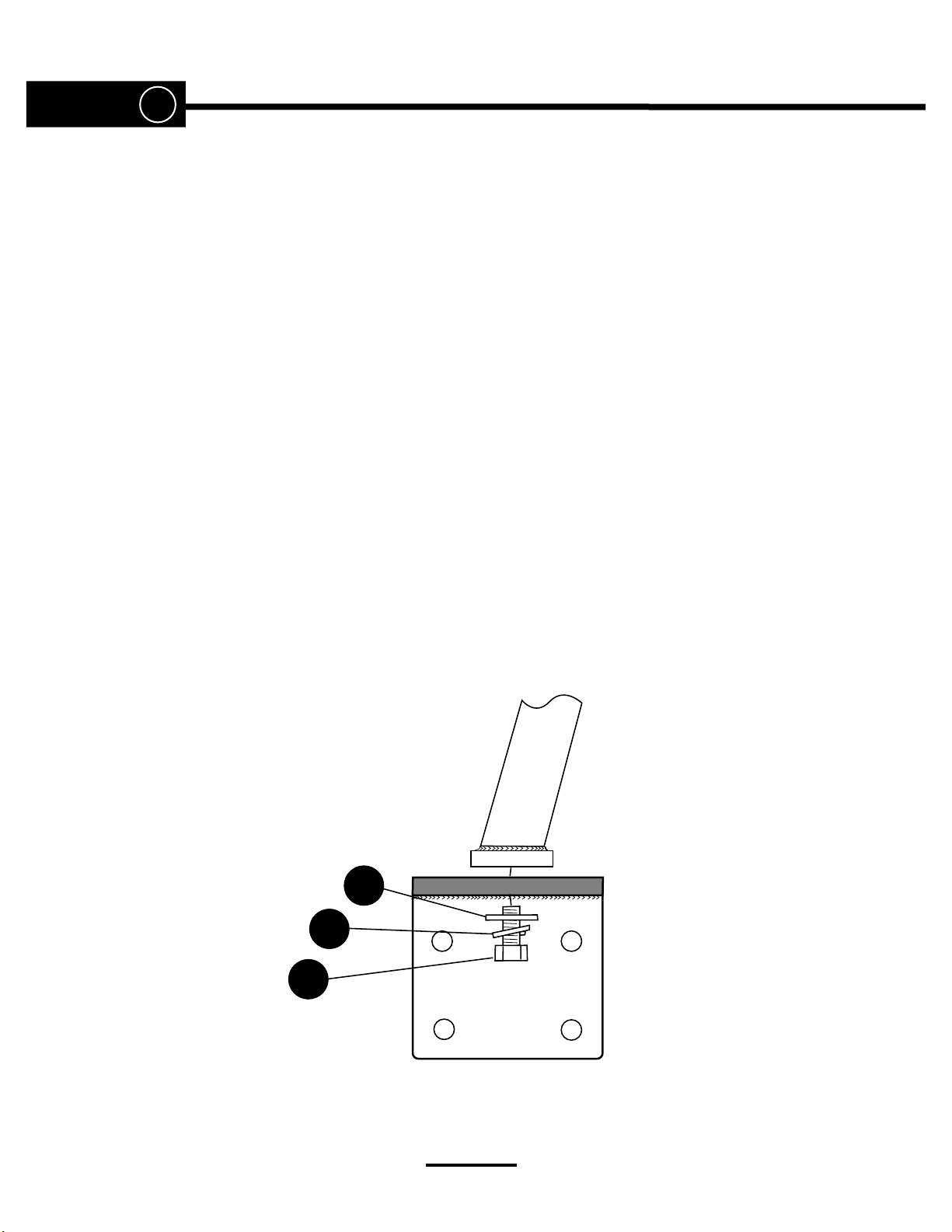
STEP 5
#1=
Set rack on the service body, with the "bulkhead angle iron mounting bracket"
centered between the boxes and pushed forward against the bulkhead. Bring the
rack approximately level, and support the rear with clamps, blocks, or forklift. Bolt
the bulkhead mounting bracket to bulkhead using bolts V, flat washers U and lock
nuts R. Push the rack forward in the mounting bracket slots so that the rear leg
mount plates are firmly against the rear of the service body boxes and position the
mounts so that the rack is level and centered. Before drilling holes in the service
body, check to ensure that the CROSS BAR is about 3" higher that the truck cab.
Drill holes with a 3/8" drill bit through the back of the boxes and attach the rear
mounting plates with button head bolts V, flat washers U and lock nuts R.
Bolt the legs (loosely) to mounting plates with bolts P , lock washers O and flat
washers H.
SRV-BODY 12_1.1
#2=
#3=
Tighten down ALL bolts except P bolts.
The lock pins (J) securing the removable rear cross bar (D) will not
slide in and out easily unless the holes are aligned. Move each
rear leg left or right in the slot to ensure proper alignment.
Tighten bolts
P.
H
O
P
Tighten down all nuts & bolts and
THAT'S IT! You are now ready to use your rack.
Page 8
A
O
V
E
R
T
U
R
N
F
O
R
C
E
LBS.
B
1 1/2”
OPTION
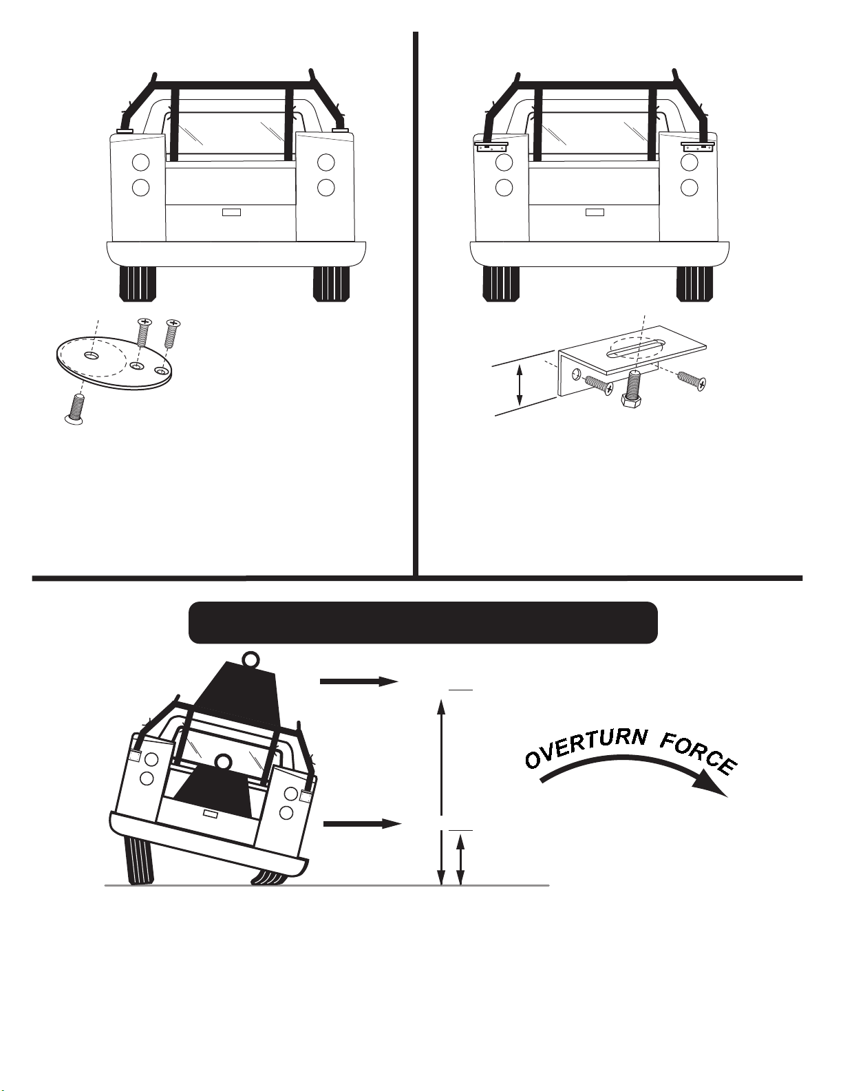
When it is not possible to attach the included rear leg mounts to the back
panel of your service body, an alternative is to mount the rear legs on top
of the box. This works for Stahl bodies and all other service bodies with
side opening boxes. In order to do this, you must purchase our accessory mount kit #70050 that includes shorter rear legs and a small mount
plate that enable you to bolt the legs to the top of the box.
WITH THIS MOUNT, THERE IS NO HIEGHT ADJUSTMENT.
PURCHASED SEPARATELY:
A
DON'T OVERLOAD YOUR VEHICLE!
LBS.
LBS.
LBS.
OPTION
When it is not possible to attach the included rear leg mounts to the back
panel of your service body in the ATTACHING AREA as shown on page 1,
an alternative is to mount the rear legs below the box lid and above the tail
light/box lock. This works on all service bodies that do not have plastic back
panels. In order to do this, you must purchase our accessory mount kit
#70050 that include shorter legs and horizontal angle iron mount brackets
(1 1/2” total height) that will fit below the box lid and above the obstruction.
WITH THIS MOUNT, THERE IS NO HEIGHT ADJUSTMENT.
@
@
100" = X3 lbs.
35" =
x1 lbs.
B
PURCHASED SEPARATELY:
12_1.1
WEIGHT CARRIED ABOVE THE FLOOR OF THE TRUCK BED (E.G. ON AN OVERHEAD TRUCK RACK) WILL
SIGNIFICANTLY INCREASE THE VEHICLE'S TENDENCY TO OVERTURN. ALWAYS KEEP HEAVY LOADS EVENLY
DISTRIBUTED AND AS LOW AS POSSIBLE. IT IS IMPORTANT TO NOTE THAT THE KARGO MASTER RACK LOAD
BEARING CAPACITY OF 1700 LBS. MAY BE GREATER THAN YOUR TRUCK'S GAWR OR GVWR CAPACITY, AND IS
PROBABLY GREATER THAN THE WEIGHT THAT CAN BE SAFELY CARRIED OVERHEAD.
For TECHNICAL SUPPORT Call: 1.800.343.7486
HOURS: Monday- Friday 8:00 A.M. to 4:30 P.M. ( PACIFIC )
 Loading...