

Page 1
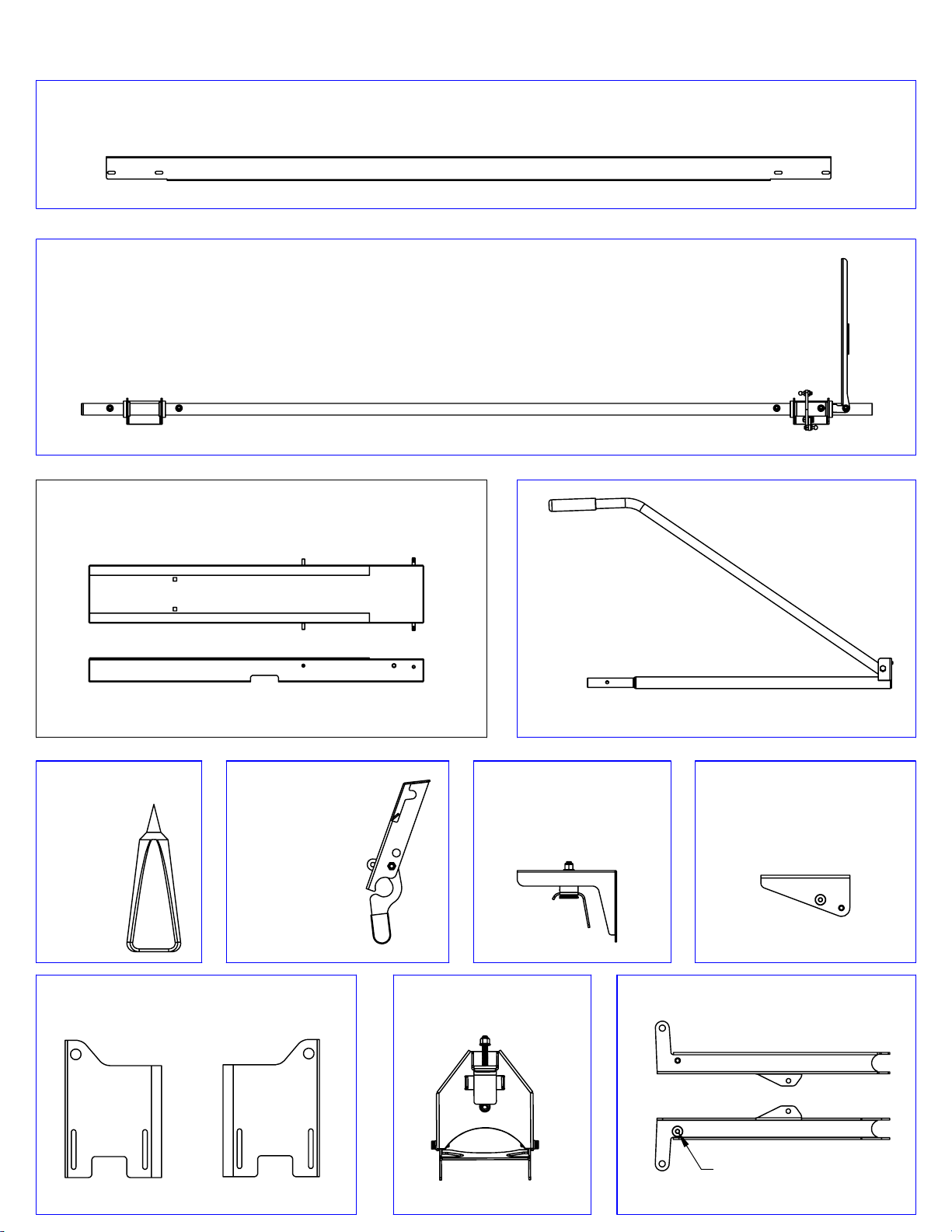
40863 Parts List
Ladder Pan
Item -005
QTY 2
Ladder Pan Stiffener
Item -031
Qty 1
Drive Tube Assembly
Item -029
Qty 1
E-6000
QTY 1
Latch Assembly
E-6000
Hold Down Plate
Item -008
QTY 2
Item -060
Qty 1
Crank Assembly
Hold Down Assembly
Item -007
Hinge Assembly
Item -006
QTY 2
Item -026
Qty 1
QTY 2
Spring/Damper Mount
Item -048
QTY 1
Lift Arm
Item -030
QTY 1
1-Left
1-Right
Welded
Spud
Lift Arm
Item -027
Qty 1
Page 2
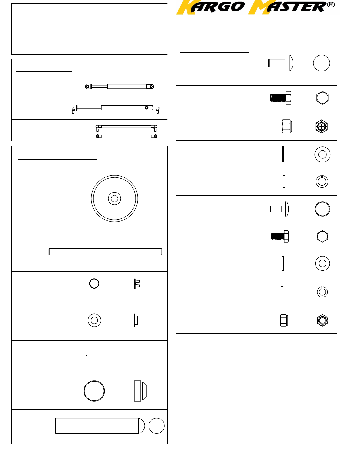
Tools Needed
5/16 Allen Wrench
8' Tape Measure
7/16 Socket
1/2 Socket
Motion Pack
Qty 1 -Damper
Qty 1 -Spring
Qty 2 -Links
Component Pack
Qty 4
Wheel
Item -002
9/16 Socket
1/2 End Wrench
9/16 End Wrench
Small Hammer
40863 HARDWARE LIST
Hardware Pack
(a)
Qty 3 3/8-16 x 1 Carriage Bolt
(d)
Qty 6 3/8-16 x 3/4 Hex Bolt
(c)
Qty 2 3/8-16 Nylock Nut
(b)
Qty 8 3/8 Flat Washer
(e)
Qty 6 3/8 Lock Washer
(f)
Qty 2 5/16 x 3/4 Carriage Bolt
Qty 2
Axle
Item-003
Qty 4
Wheel Cap
Item -004
Qty 4
Flange Bushing
Item -036
Qty 8
Nylon Washer
Item -038
Qty 2
Bump Stop
Item -049
(s)
Qty 8 5/16-18 x 3/4 Hex Bolt
(k)
Qty 24 5/16 Flat Washer
(p)
Qty 8 5/16 Lock Washer
(h)
Qty 16
5/16 Nylock Nut
Qty 1
Ladder Stop
Item -009
Page 3
STEP 1
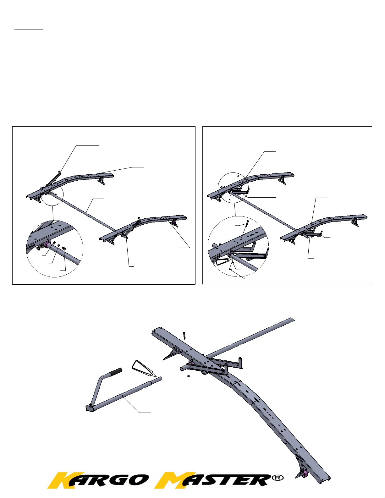
Install pre-assembled drive tube assembly (-029) into cross bows (-001)
with cam end of the tube to the front of the van. Attach through 3/8" round
holes on edge flange of bow. Use 4 each 3/8" x 3/4" hex bolts (d), 4 each 3/8"
flat washers (b) and 4 each 3/8" lock washers (e) per
hardware (g) (k) (h) and
coat bolts with E-6000 to seal bolt hole in tube.
5/16" x 2" hex bolts (g), 5/16" flat washer (k) and 5/16" nylock nuts (h) per
[Diagram 5]
and tighten.
Note: Cross bows and gutter mounts are not included in the 40863 kit.
[Diagram 4]
. Next, remove
Re-insert
DIAGRAM 4
Shock and Cam Assy
towards front of van
Cross Bow
(-001)
(not Included
in 40863)
Drive Tube Assy
(-029)
Cross Bow
(-001)
(b)
(e)
(d)
NOTE:
crank tube (-026) per
The rear lift arm bolt will need to be removed to insert crank tube (-026). Install
[DIAGRAM 5b]
through sleeve in the crank arm.
before assembly to prevent moisture inside.
crank tube assy
rear
and reinstall lift arm bolt. Bolts must line up
Coat swaged end of crank tube with E-6000
DIAGRAM 5
(g)
E-6000
(k)
(h)
Lift Arm
(-030)
Lift Arm
(-027)
Lift Arm
(-030
Note: Welded
Spud
Lift Arm
(-027)
E-6000
crank tube
(-026)
DIAGRAM 5b
For TECHNICAL SUPPORT Call: 800-343-7486 Monday - Friday 8:00 A.M. to 4:30 P.M. (PST)
Page 4
STEP 2
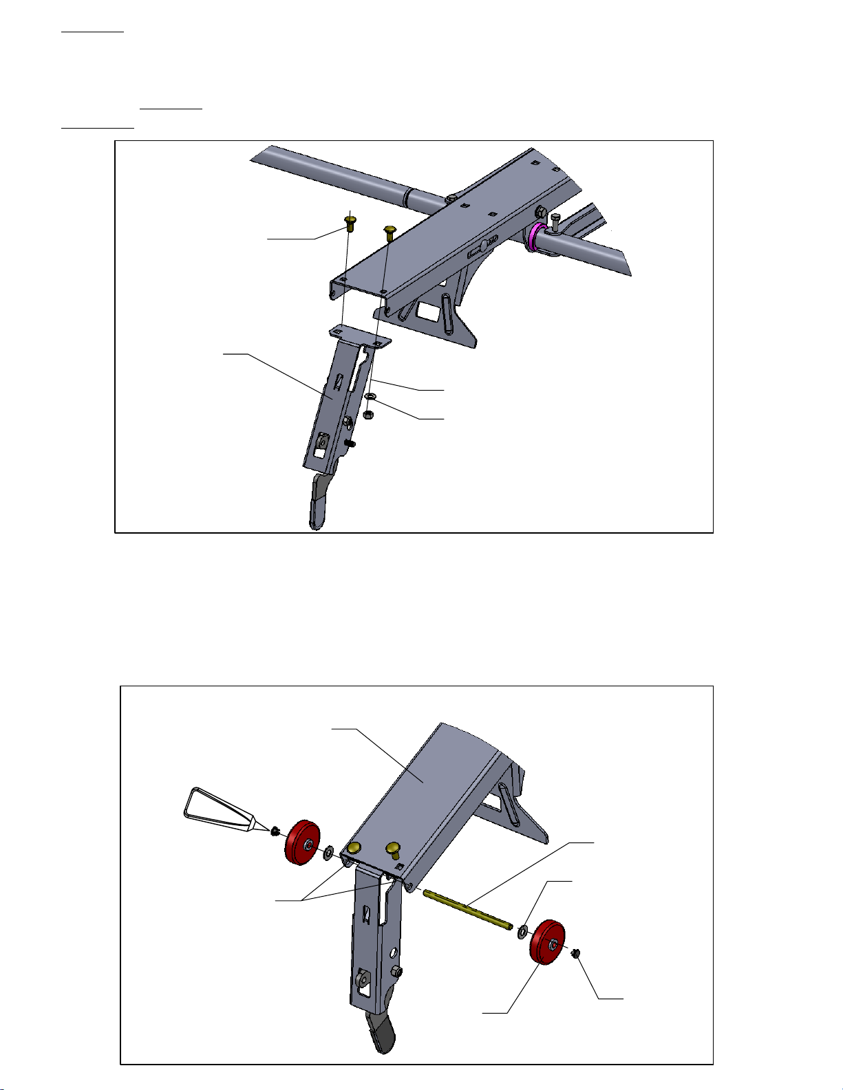
Install rear arm lock bracket (-060) to bottom of rear cross bow per
11]
. Attach with 2 each 5/16 x 3/4 carriage bolts (f) 2 each 5/16 flat washers
(k) and 2 each 5/16 nylock nuts (h).
bracket
through
before
inserting axle in the following step (axle must pass
bracket).
Rear Arm
Lock Bracket
(-060)
(f)
NOTE:
(k)
(h)
You will need to attach this
[Diagram
DIAGRAM 11
Install 5/16" axle rods (-033) trhough holes "A" in the cross bow channel
(-031). Install nylon washer (-038 ) on each side of bow per
[Diagram 1]
.
Next, slip on the wheels (-002) and use a small amount of E-6000 on wheel
caps (-004) then insert into the ends of the wheels. Repeat procedure on
other cross bow.
Cross Bow
(-001)
E-6000
Axle
(-003)
Nylon Washer
(-038)
Holes "A"
DIAGRAM 1
Wheel
(-002)
Wheel Cap
(-004)
Page 5
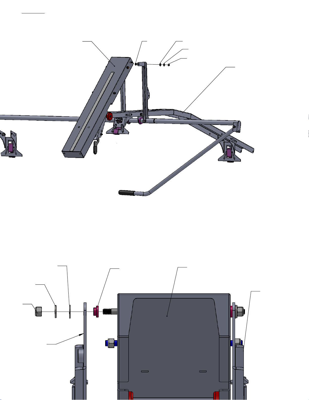
STEP 3
Next, drop ladder pan (-005) over wheels through side slots in pan and line up
holes in arms (-027 / -030).
(-038)(-036)(-005)
(k)
(m)
Existing Cross
Bows and feet
(not included
in the 40863 kit)
Now insert flange bushing(-036) between pan(-005) and arm(-027/-030) as
shown in
arm(-027/-030) and flat washer(k), then 5/16 nylock(h) per
tighten. Follow same procedure on each arm.
Nylon Washer (x2)
5/16 Flat washer
(k)
5/16 Nut
(m)
Lift Arm
(-027)
[DIAGRAM 6A].
(-038)
Now Insert nylon washer(-038) on the outside of lift
[DIAGRAM 6A]
Parts should rotate freely.
Flange Bushing
(-036)
Ladder Pan
(-005)
and
Lift Arm
(-030)
DIAGRAM 6A
Page 6
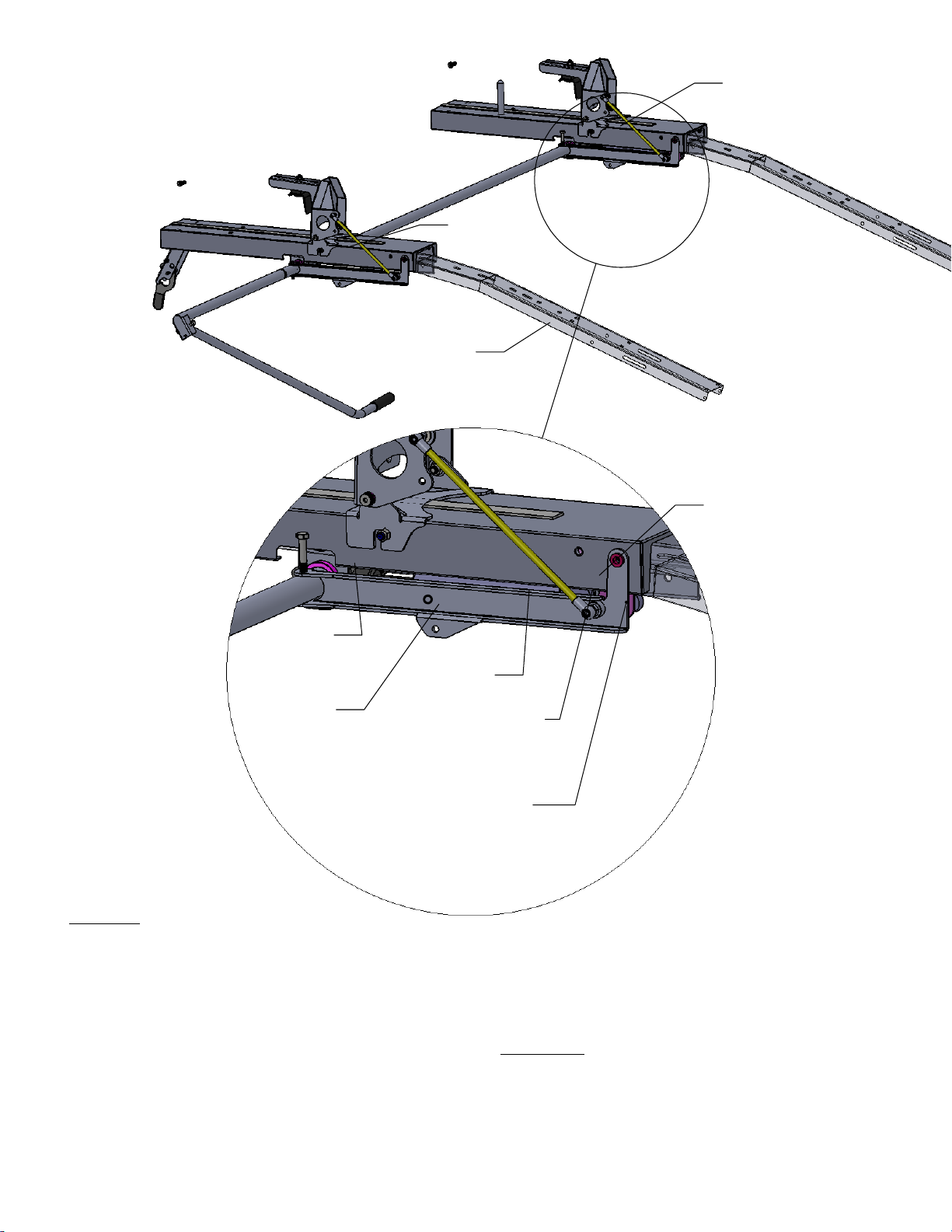
FRONT
Bump Stop
(-049)
REAR
Bump Stop
(-049)
Existing Cross Bows
(not included
in the 40863 kit)
Mount
(-048)
Cam Plate
Damper
Spring
Mounting
Location "B"
Mounting
Location "A"
STEP 4
Now insert 2 each bump stops (-049) into 1/2" holes on top of cross bows with
flat side facing up. Install spring/damper mount (-048) with offset installed per
[DIAGRAM 7]
washers (b) and 2 each 3/8 nylock nuts (c).
Please Note:
spring and damper. Now attach damper (large tube end) to spring/damper
mount (-048) in mounting location "B". Snap large end onto ball stud. Next, insert
rod end and snap onto ball stud in cam plate. Now install the gas spring (large
tube end) to spring/damper mounting location "A". Snap large end onto ball
stud. Next, with rack in lowered position insert rod end and snap onto ball stud
in cam plate.
. Fasten using 2 each 3/8 x 1 carriage bolts (a), 2 each 3/8 flat
Gas spring is identified by a
red dot
on barrel. Besure not to mix the
Page 7
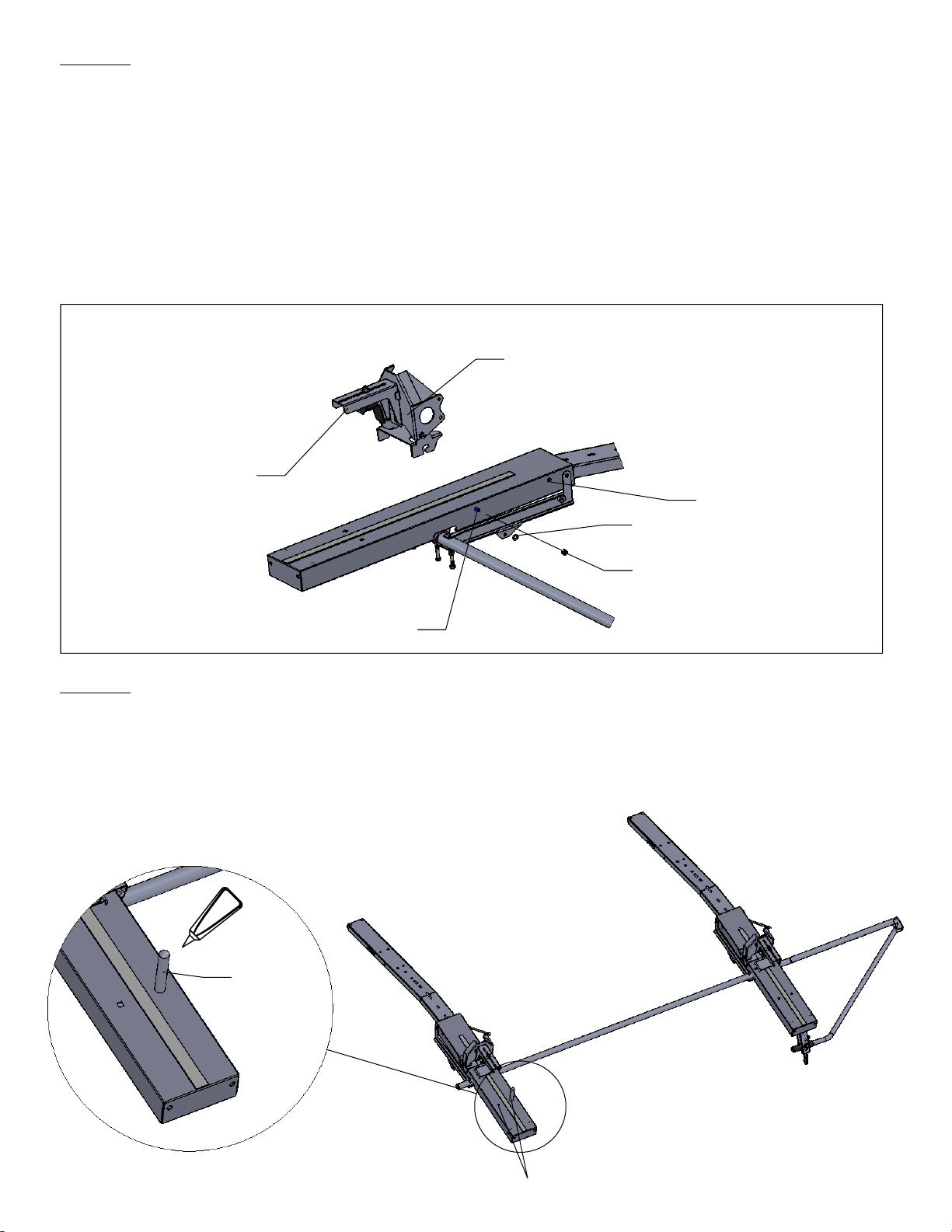
STEP 6
Install hold down assembly (-007) to the pre-assembled hinge bracket
assembly (-006) using 3/8 x 3/4 hex bolt (d) 3/8 flat washer (b) and 3/8 lock
washer (e). Next, attach to ladder pan (-005) per
for extension ladders and location #2 for rear step ladders with wider base.
For location #1, secure hinge assembly (-006) using 2 each 5/16 flat washers
(k) and 5/16 nylock nuts (h). Be sure (-006) is seated all the way into rear of
slot (if not, linkage timing on hold down could be effected).
For location #2 (wide end of step ladder) secure with 2 each 5/16 flat washers
(k) 2 each 5/16 lock washers (p) and 2 each 5/16 x 5/8 hex bolts (s).
Hinge
Assembly
(-006)
Hold Down
Assembly
(-007)
[DIAGRAM 2]
Location #2
(k)
(location #1
(h)
Location #1
STEP 7
Insert ladder stop (-009) 1 per. Secure using 3/8 x 1 carriage bolt (a) from bottom
side (apply a small amount of E-6000 on threads). Choose one of the two 3/8
square holes so when the ladder is moved forward against stop, ladder stop will
be positioned correctly on ladder side rail per
E-6000
Ladder
Stop
(-009)
[DIAGRAM 3b]
.
DIAGRAM 3b
Front
3/8 Square Holes
Page 8
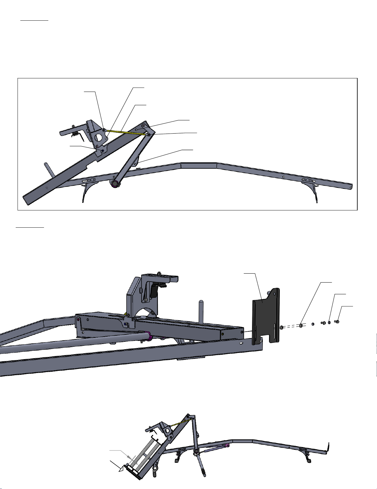
STEP 8
Install link rods. Depending on the location of the hinge bracket assembly (-006),
location #1 will require link rod to attach to hole "E" and "H" per
Location #2 (which is step ladder wide end) will require the link rod to attach to
hole "F" and "G". Note: Hole "H" is threaded to allow rod end to screw directly into
bracket. All other holes will require 1each 5/16 flat washer (k) and 1each 5/16
nylock nut (h).
[DIAGRAM 12]
.
Hole "E"
Location #1
Hole "F"
Link Rod
Location #2
Hole "H"
Hole "G"
DIAGRAM 12
STEP 9
I
nstall hold down plates (-008) and ladder pan stiffener(-031) using 4 each 5/16 flat
washers (K), 4 each 5/16 lock washers (p) and 4 each 5/16 x 3/4 hex bolts (s) only
after assembly is complete. Hand tighten hardware.
Hold Down Plate
(-008)
(k)
(p)
Next position the front hold down plate (-008) approximately 1/8" from top of the
ladder side channel. This gap will ensure the ease of ladder insertion into the front
ladder pan. Bring rear hold down plate in slight contact with side channel (rear
should be snug to prevent ladder movement in transport). Now tighten hardware.
1/8"
(s)
Front
Page 9
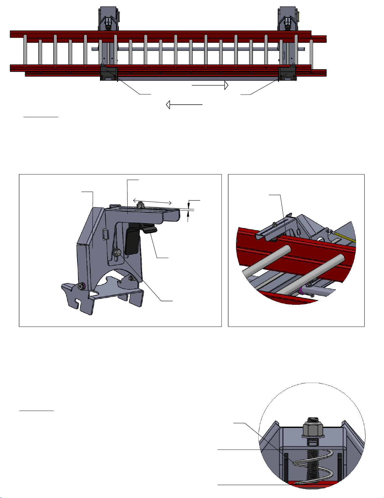
DIAGRAM 3
Hold Down Plates (-008)
STEP 10
With ladder placed against hold down plates (-008) per
ladder (front to rear) to a position that allows clamp (-010) to register on ladder
side channels in a location that allows (face) to contact the flat on the ladder
side channel. Move clamp (-010) so that it is in proper location in hold down
assembly (-007). Tighten so 1/8" of stud is extended through nut shown in
[DIAGRAM 3d]
.
[DIAGRAM 3]
move
Hinge Assembly
(-006)
Hold Down Assembly
(-007)
1/8"
(-010)
(d)
DIAGRAM 3d
(-010) flat on
ladder side
channels
DIAGRAM 3c
Next, loosen the 3/8 x 3/4 hex bolt (d). Push down on the hold down assembly so
the spring is compressed about 1/2" to 3/4" when the rack is down in transport
position. This will ensure that there is enough pressure placed on the ladder to
prevent movement. Now tighten bolt (d) to hold position. Rotate crank handle up
and down and inspect for proper clamping action.
STEP 11
If no other accessories are to be used
on the opposite side, you may want
to install the load lock plates (-070) so
other materials may be carried. Use
5/16 x 3/4 carriage bolts (f) 5/16 flat
washers (k) and 5/16 nylock nuts (h).
See
[Diagram 8]
on the next page.
Spring
Compress
1/2" to 3/4"
 Loading...