

Page 1

ASSEMBLY INSTRUCTIONS
for :
PRO-II
PLATFORM BODY
09.9.9
(916) 638-8703
®
(800) 343-7486
• 11253- G Trade Center Drive • Rancho Cordova, CA 95742 •
Page 2
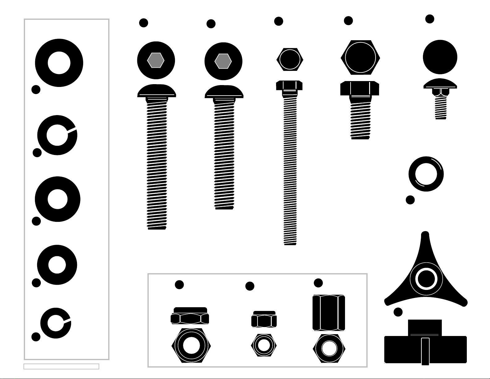
H
(18 ea.)
1/2" SAE Flat Washer
O
(10 ea.) 1/2" Lock Washer
V
(2 ea.)
1/2" x 3"
Button Head Bolt
G
(2 ea.)
1/2" x 2 1/2"
Button Head Bolt
(2 ea.)
K
3/8" x 3 1/2"
Tap Bolt
(10 ea.)
P
1/2" x 1"
Hex Bolt
(8 ea.)
Q
5/16" x 3/4"
Carriage Bolt
U
(4 ea.) 3/8" SAE Flat Washer
L
(8 ea.) 5/16" Flat Washer
E
(2 ea.) 3/8" Lock Washer
©2009 KARGO MASTER --Platform 2:1
I
(4 ea.)
1/2" Jam Nut
M
(8 ea.)
5/16" Lock Nut
N
(2 ea.)
3/8" Coupling Nut
W
(2 ea.)
Z
Rubber O-Ring
(2 ea.)
Plastic Knob
Page 3
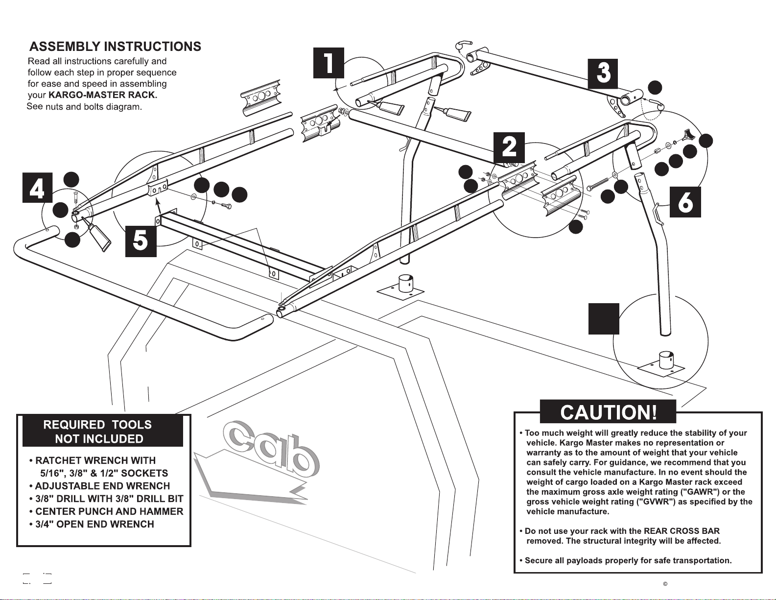
PRO II - PLATFORM BODY
4
1
4
S
i
l
i
c
o
n
e
S
i
l
i
c
o
n
e
2
G
H
O
P
Z
S
i
l
i
c
o
n
I
e
5
MOUNT TABS
M
L
U
K
Q
J
W
E
U
N
77
PLATFORM BODY
EXISTING
CAB GUARD
www
r
w
a
you
fo
d
t
i
com
2006 KargoMaster-Platform 06.2:1
Page 4
PLATFORM
BEFORE YOU BEGIN, PLEASE VERIFY THAT THIS RACK WILL FIT YOUR PLATFORM BODY.
This rack will fit platform bodies that are at least 84" wide, with cab guards that are in the range of 38" - 48" high.
BEFORE YOU BEGIN, PLEASE VERIFY THAT THE RACK WILL FIT YOUR BODY.
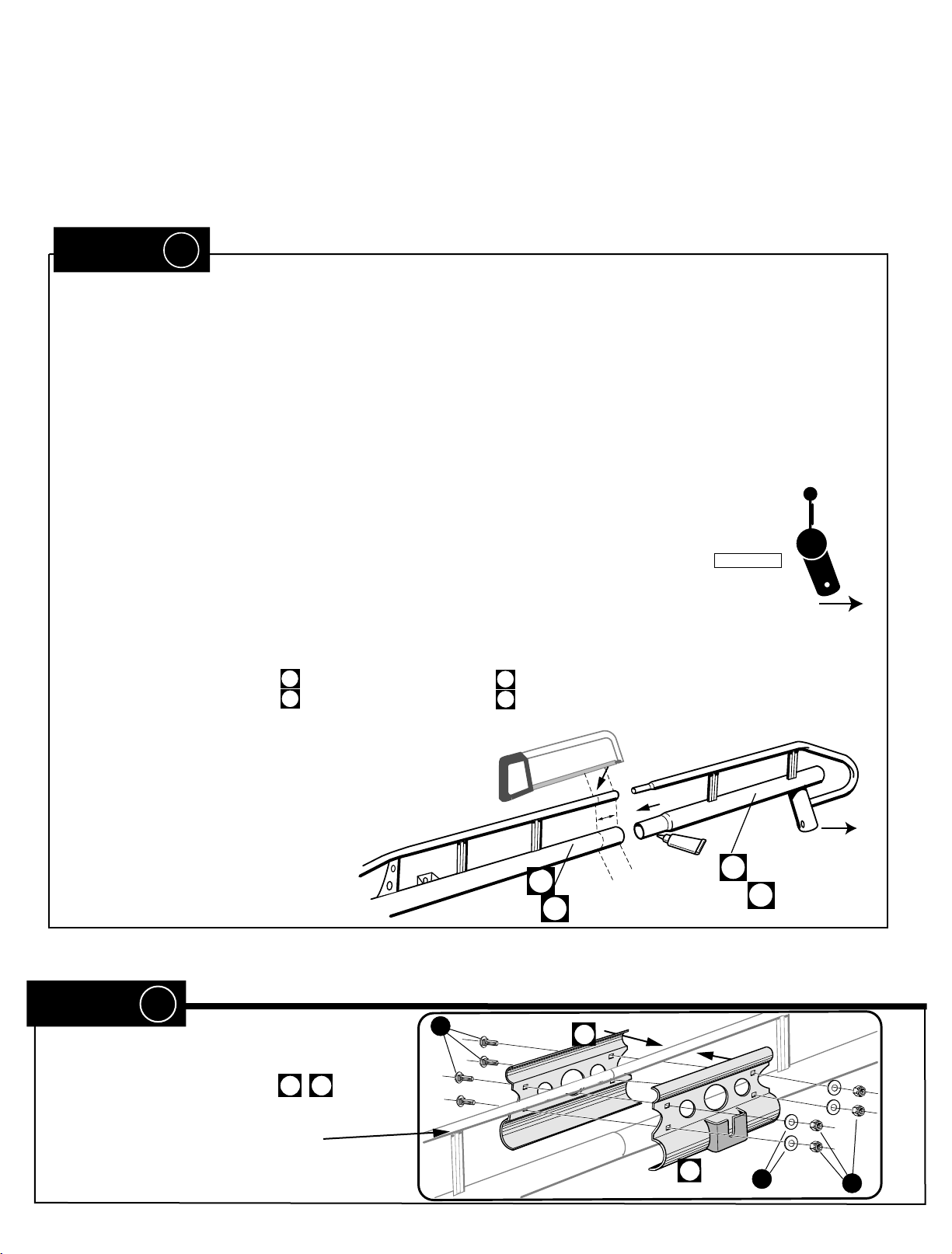
STEP 1
#1= The FRONT SIDE BEAMS are made to fit bodies that are 96" (78000 & 78001), 108" (79000) and 144" (71200)
long. This length is measured from the back of the cab guard to the back of the body frame. If the rack is too long for
your body, it can be shortened by: A- reversing the FRONT CROSSBAR so that the mount tabs are positioned in front
of the cab guard - TRY THAT FIRST; or B- cutting the FRONT SIDE BEAMS as indicated. With CROSSBAR tabs
positioned behind the cab guard as shown, measure the distance from the back of your cab guard to the back of your
body. If for example, this distance is 94", cut 2' off of a 78000 Series rack or 14" off a 79000 Series rack.
#2= Cover entire swedged joint surfaces with silicone sealant.
IMPORTANT:
Before sliding the front side channel into the rear, make certain that
(truck bed side)
you have matched a right front with a right rear. The front side channels have a clip on one
side, the inside. The leg cups on the front and rear side channel must both slant outward,
this view is from rear,
passanger side (leg cup
slanting outwards, away from truck)
away from the center of the truck bed. please refer to the rear view shown here.
#3= Slide REAR SIDE BEAMS into FRONT SIDE BEAMS . If the swedged portion of the REAR SIDE BEAM
03
05
04
06
does not easily slide completely into the FRONT SIDE BEAM, place a
piece of cardboard shipping box on the ground, lift the
joined FRONT and REAR SIDE BEAM assemblies into a
vertical position with the REAR SIDE BEAM down, and
gently tap the rounded bottom of the REAR
SIDE BEAM on the cardboard.
(inside clip)
outside
03
05
(left)
(right)
(truck bed inside)
outside
S
i
l
i
c
o
n
e
04
(left)
06
(leg cup slanting
outwards)
(right)
STEP 2
#1= Attach CLAMP PLATES centered
at tube joint, with slotted brackets towards
inside of RACK, with Q, L, M.
7 7a
Q
E
D
I
S
N
I
7
7a
L
M
Page 5
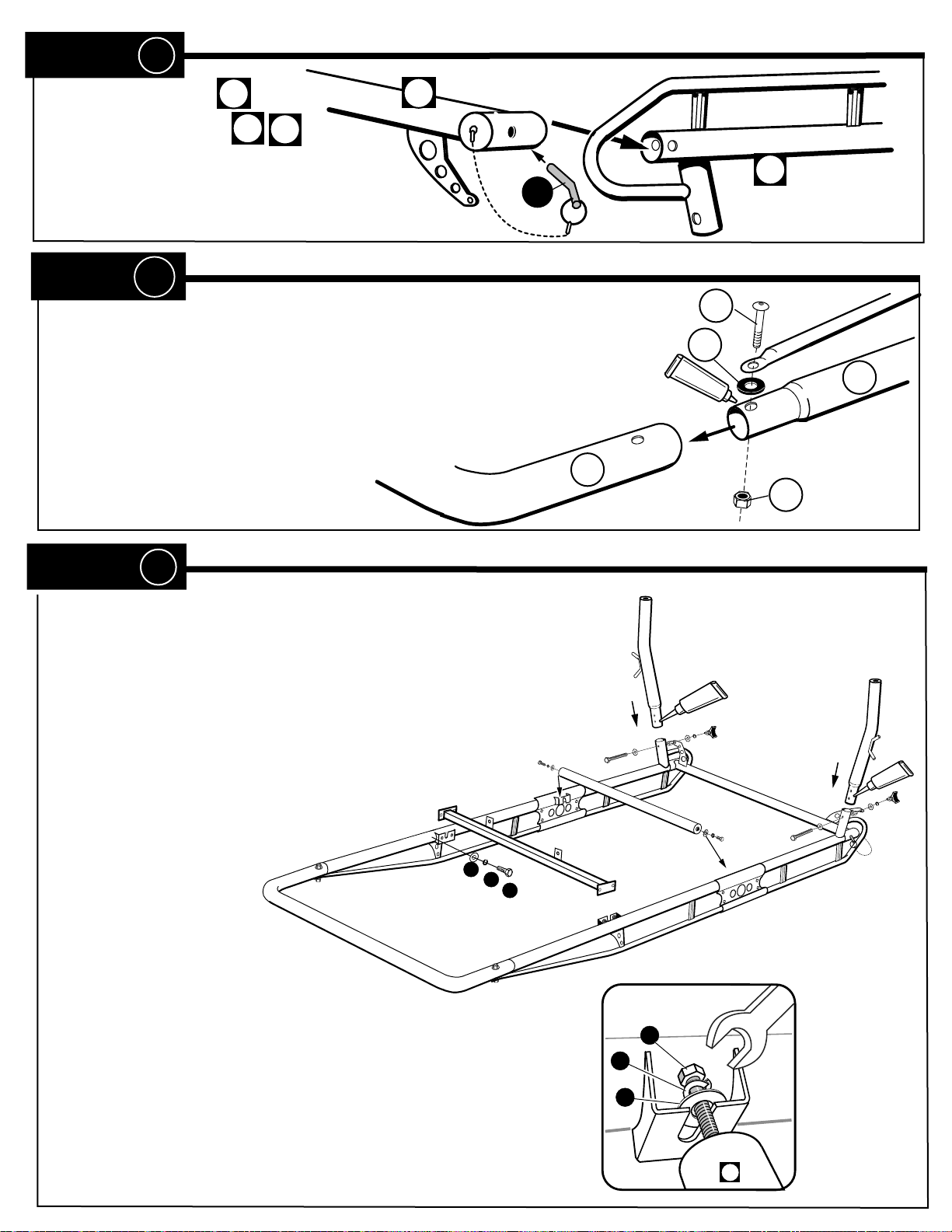
STEP 3
platform
#1= Slide REAR BAR on to
REAR SIDE BEAMS
#2= Fully insert LOCK PINS J completely
D
04
06
J
D
J
to the bend of the pin.
STEP 4
#1 = Cover entire swedged joint surfaces with silicone sealant.
Slide FRONT CROSS BAR
#2 = BOLT TOGETHER with rubber washer Z, between TOP (small tube)
& SIDE RAIL (large tube), as shown, using bolt
The allen wrench is included in the package.
A into FRONT SIDE BEAMS 03 & 05.
G & nut I.
A
06
G
Z
Silicone
05
I
STEP 5
#1= Turn partially assembled rack upside down as shown. Cover entire
swedged joint surfaces with Silicone sealant, Then insert the swedged end of
each REAR leg , rope hooks facing outward, into the short tubes projecting
from the bottom of the SIDE BEAMS.
#2= Attach CROSS BAR to siderails with bolts P, lock washers O and flat
washers H. Be sure to orient the CROSS BAR so that the mount
tabs are behind the cab guard, unless it is neccessary to
move the rear legs forward as described in STEP
1 before.
H
O
P
#3= At each end of MIDDLE CROSS BAR start
BOLTS & WASHERS Slide BOLTS & WASHERS into
SLOTTED BRACKETS on the INSIDE CLAMP
PLATES
(included in this package)
, snug with an open end 3/4" wrench
E
N
O
C
I
L
I
S
E
N
O
C
I
L
I
S
44
//
P
O
H
33
C
Page 6
platform
STEP 6
#1= Set rack on platform body, with the CROSS BAR centered on and pushed forward against the cab guard.
Center the rear legs on the rear of the body, and set each leg into the cup on the rear mount bracket. If the rack is
not level, measure the amount that must be cut from the bottom of each rear leg. Remove the legs from the rear of
the rack and cut.
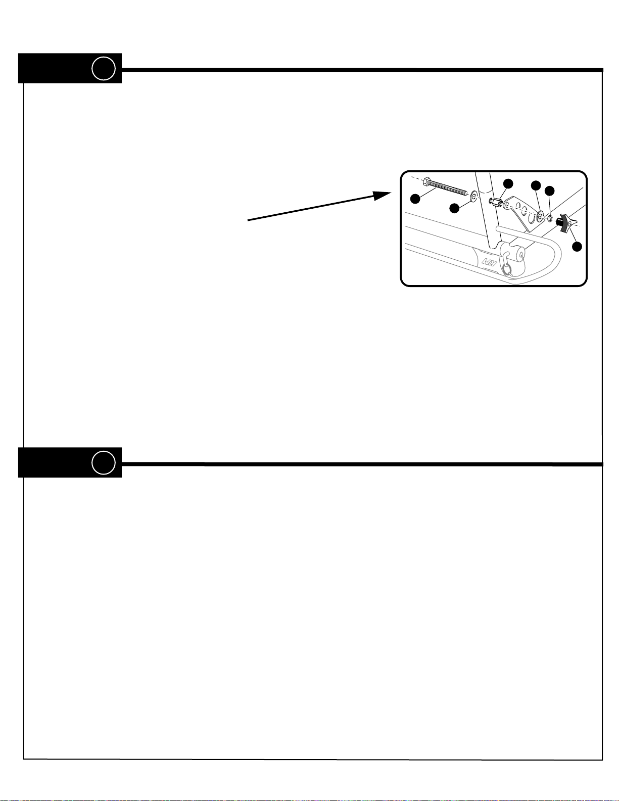
#2= Reinsert REAR LEGS. Bolt REAR
LEGS and REAR BAR BRACE (as shown),
with bolts K , washers U , lock washers E,
coupling nut N, & knob W.
Attach the CROSS BAR tabs to the cab guard by welding or by drilling
(7/16") and tapping (1/2"-13) two holes in the cab guard and bolting with
bolts P, lock washers O, and washers H.
K
U
N
U
E
W
NOTE: The lock pins (J) securing the removable rear cross bar (D) will not slide in and out easily unless the
holes are aligned. Move each rear leg left or right slightly to ensure proper alignment before permanently
attaching.
STEP 7
#1= Rotate the bracket 180 deg. so that the mount plate and holes are sitting optimally on the steel channel
frame of the platform body. Attach the rear mount bracket plate to the frame of the platform body by welding or
by drilling (7/16") and tapping (1/2"-13) four holes in the frame and bolting with bolts P, lock washers O, and
washers H.
#2= Secure the rear legs to the mounting cups by either nut & bolt (G, H, & O) after drilling appropriate hole
in leg, or plug welding.
Tighten ALL bolts and...
THAT'S IT!
06.2.1
Page 7
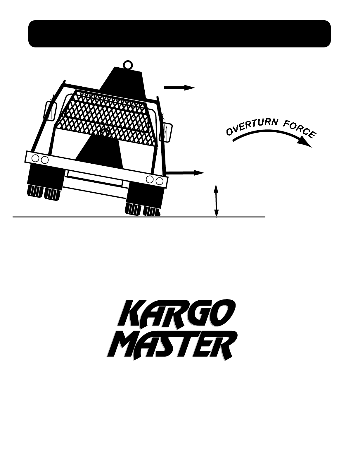
DON'T OVERLOAD YOUR VEHICLE!
O
V
E
R
T
U
R
N
F
O
R
C
E
LBS.
@
LBS.
100" = 3X lbs.
@
WEIGHT CARRIED ABOVE THE FLOOR OF THE TRUCK BED (E.G. ON AN OVERHEAD TRUCK RACK)
WILL SIGNIFICANTLY INCREASE THE VEHICLE'S TENDENCY TO OVERTURN. ALWAYS KEEP
HEAVY LOADS EVENLY DISTRIBUTED AND AS LOW AS POSSIBLE. IT IS IMPORTANT TO NOTE THAT
THE KARGO MASTER RACK LOAD BEARING CAPACITY OF 1700 LBS. MAY BE GREATER THAN YOUR
TRUCK'S GAWR OR GVWR CAPACITY, AND IS PROBABLY GREATER THAN THE WEIGHT THAT CAN BE
SAFELY CARRIED OVERHEAD.
35" = X lbs.
®
For TECHNICAL SUPPORT Call:
1-800-343-7486
HOURS: Monday- Friday 8:00 A.M. to 4:30 P.M. (PACIFIC )
 Loading...