

Page 1

ASSEMBLY INSTRUCTIONS
for :
80070 TOP MOUNT
CAMPER SHELL
and TRANSIT CONNECT
RACK
TMCS_3:1
®
(916) 638-8703
• 11261 Trade Center Drive • Rancho Cordova, CA 95742 •
(800) 343-7486
• www.kargomaster.com •
Page 2
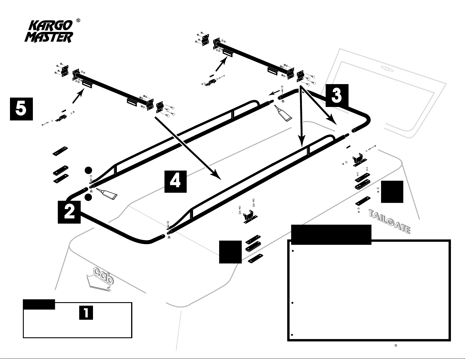
ASSEMBLY INSTRUCTIONS
Read all instructions carefully and follow each
step in proper sequence for ease and speed in
assembling your KARGO-MASTER RACK.
See below for nuts and bolts diagram.
80070 Top Mount
Camper Shell & Transit
Connect Rack
5
2
Camper
G
O
O
P
Transit
B
3
4
G
O
O
P
L
WARNING!
WE RECOMMEND THAT YOU NOT EXCEED 200 LBS. OF EVENLY
88
SPACED CARGO. TOO MUCH WEIGHT COULD DAMAGE YOUR
CAMPER SHELL. KARGO MASTER MAKES NO REPRESENTATION
OR WARRANTY AS TO THE AMOUNT OF WEIGHT THAT CAN BE
CARRIED SAFELY BY OR WITHOUT DAMAGING YOUR SHELL. FOR
GUIDANCE, WE RECOMMEND THAT YOU CONSULT THE CAMPER
SHELL MANUFACTURER.
1111
NOTE:
Shaded numbers ( ) in this view
correspond to instruction steps in this
assembly package.
DRILLING HOLES IN THE CAMPER SHELL ROOF MAY VOID THE
WARRANTY. WE RECOMMEND THAT YOU HAVE AN AUTHORIZED
CAMPER SHELL DEALER DRILL AND MOUNT THE RACK FOOT
PLATES.
SECURE ALL CARGO PROPERLY FOR SAFE TRANSPORTATION.
2012 KargoMaster-TMCS-3:1
Page 3
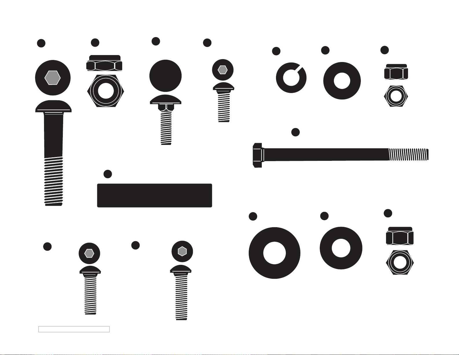
A
(4 ea.)
1/2" x 2 1/4"
Button Head Bolt
B
(4 ea.)
1/2" Nyloc Jam Nut
(4 ea.) Mounting Bracket Spacers
N
(16 ea.)
E
5/16" x 1"
Carriage Bolt
(8 ea.)
G
5/16" x 3/4"
Button Head Bolt
H
(8 ea.)
5/16" Lock Washer
(4 ea.)
K
3/8" x 4"
Hex Bolt
80070 Bolt Kit
I
(32 ea.)
5/16" Flat Washer
J
(24 ea.)
5/16" Lock Nut
(4 ea.)
D
M8 x 32
©2012 KARGO MASTER_TMCS 3:1
(8 ea.)
S
5/16" x 1 1/4"
Button Head Bolt
P
(4 ea.)
1/2" SAE Flat Washer
L
(8 ea.)
3/8" SAE Flat Washer
M
(4 ea.)
3/8" Lock Nut
Page 4
TMCS_3:1
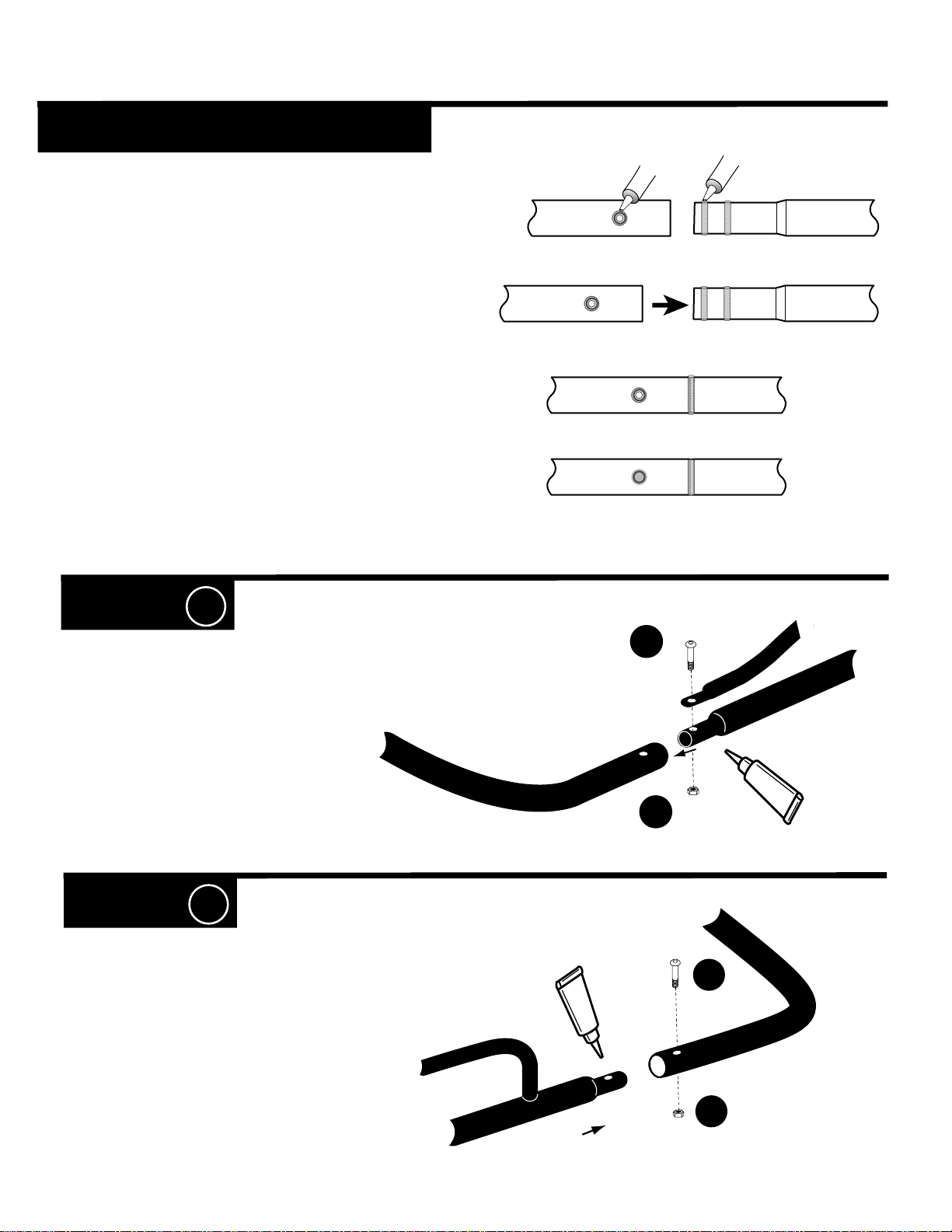
GOOP APPLICATION
Apply a healthy air tight bead of goop
around every swaged joint as shown, to
prevent moisture from leaking into and out
of the joint. If this is not done properly, the
inside surface of the tubes can rust and
rusty water can leak out. Maintain this
joint seal throughout the life of your rack.
Swaged joint & holes
GOOP
Smooth goop at swaged joint & holes
GOOP
STEP 1
#1 = Cover entire swedge joints with
goop and slide FRONT U- BAR onto side
rails and bolt together with bolts
jam nut
B.
A, and
STEP 2
#1 = Cover entire swedge joints with
goop and slide REAR U- BAR onto side
rails and bolt together with bolts
jam nut
B.
A, and
A
G
O
O
P
B
G
O
O
P
A
B
Page 5
CAMPER SHELL ONLY - Transit Connect skip to STEP 8
TMCS_3:1
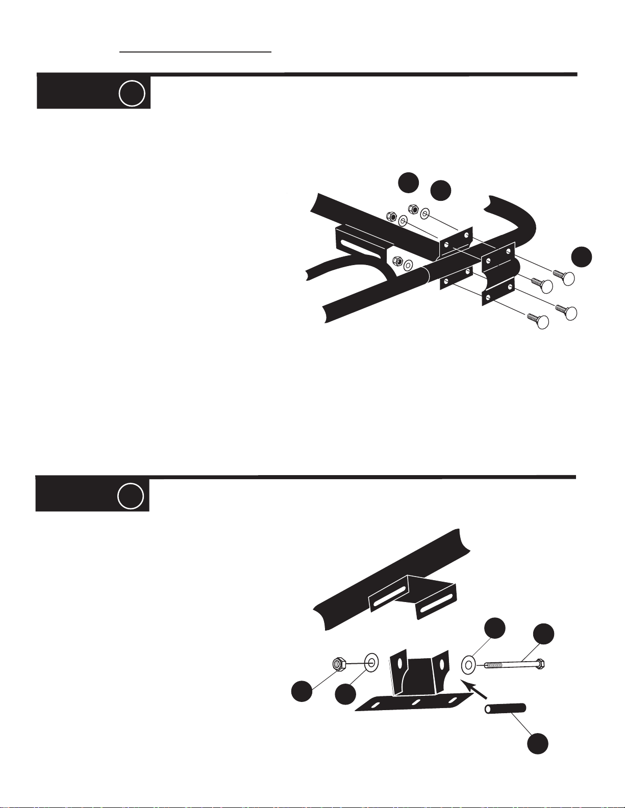
STEP 3
#1 = Position rear cross bar behind the ½” button head
A that attaches the rear U bar to the side channel.
bolt
Loosely bolt clamp plates together with bolts
and lock nuts
#2 = With the camper shell rear door fully opened,
measure the distance from the open rear door to the front
most point of the camper shell roof, where you will be
locating the front mounting plates. See diagram in STEP 5.
#3 = Position the front cross bar so that the distance from the
rear U bar to the front cross bar is as per the measurement
above. The objective is to locate the front foot as far forward on
the camper shell roof as possible, but at the same time making
sure that the opened camper shell rear door will not hit the rear
U bar. See diagram in STEP
together with bolts
J.
E, washer I and lock nuts J.
**(Camper Shell ONLY)
E, washer I
5. Loosely bolt clamp plates
J
I
E
STEP 4
#1 = There are 8 mounting feet in your box. There are
4 identical feet (these are the taller ones with the three
holed flange on the bottom). These will be used for
Camper Shell installation. Find these now.
#2 = Position the Camper Shell feet into the
slider brackets on the cross bars.
#3 = Place the spacer N inside the mounting
brackets. Loosely bolt the feet to slider brackets
using bolts
K, washers L and lock nuts M.
M
L
L
K
N
Page 6
TMCS_3:1
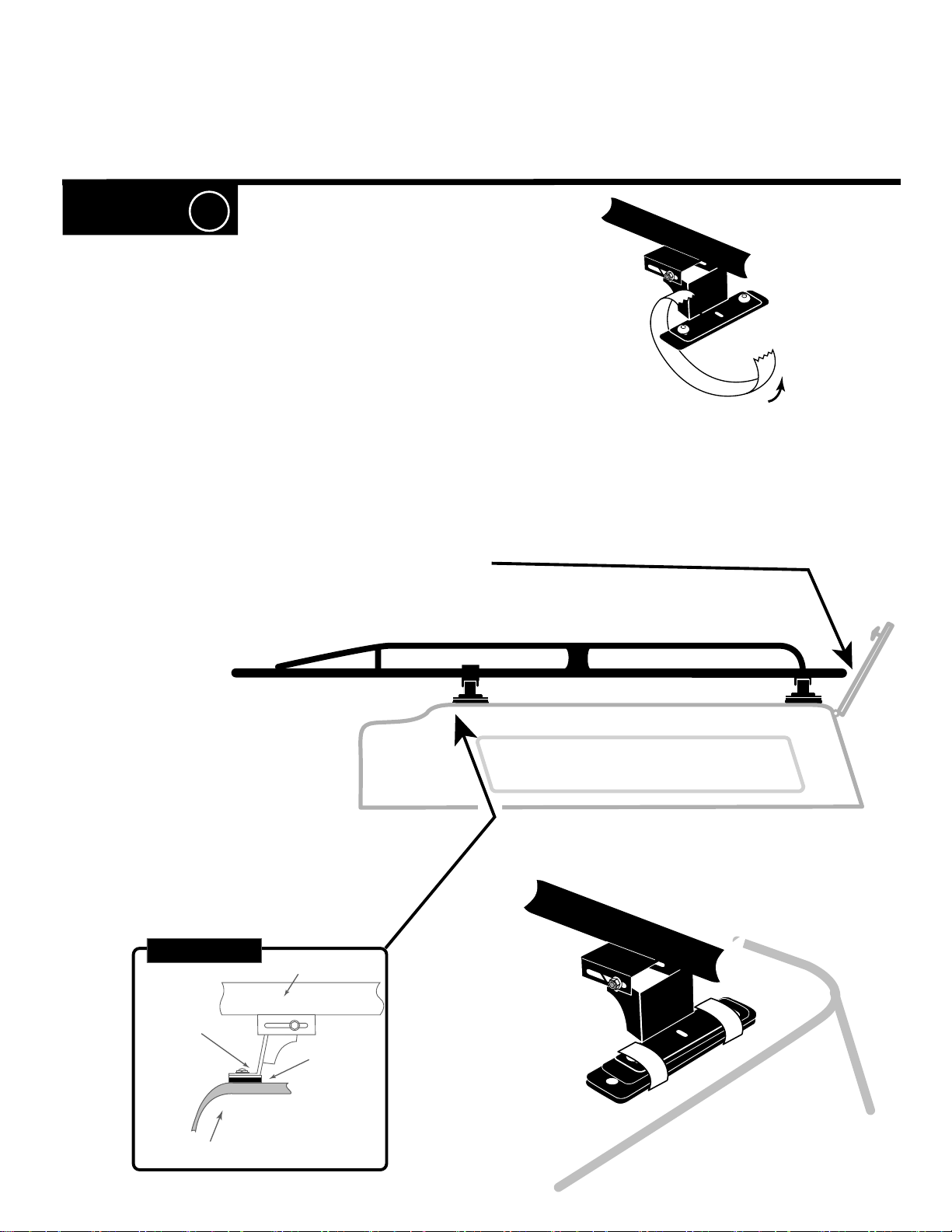
STEP 5
**(Camper Shell ONLY)
#1 = Place a rubber roof pad under each foot
flange, align the holes, and temporarily secure it in
place with tape. Do not tape over the holes.
#2 = Carefully place the assembled rack onto the top of the
camper shell and position it centered side to side. Examine
the underside of your camper shell to see if the manufacture
has molded any reinforcement pads into the roof. If so,
position the feet so that the mount bolts will go through the
pads. If not, we recommend that you consult the camper shell
manufacture for optimal foot location. Typically, the front feet
should be as far forward as possible, the rear feet should be
as far back as possible, and all feet should to the outer most
shoulder of the shell. When the rack has been positioned as
described above, BE SURE that the there is at least 2”
clearance between the rear U-bar and the fully opened rear
camper shell door. BE SURE that the INSIDE backing plate
will be clear of any obstacles inside the camper shell roof.
After final positioning, tighten down the cross bar clamps.
2“
DIAGRAM #1
Feet Flange
Fiberglass
Camper Shell
( inside )
Rack
Cross Beam
Rubber
Roof Pad
Page 7
TMCS_3:1
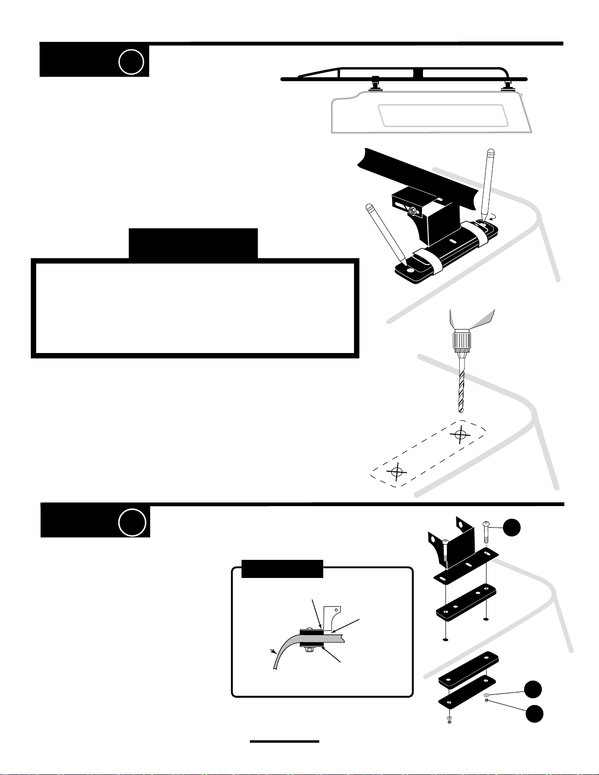
STEP 6
**(Camper Shell ONLY)
NOTE: Be sure that the INSIDE backing plate will be
clear of any obstacles inside the camper shell roof.
#1 = With the rack properly positioned, mark the
TWO outer holes (not the middle hole) on the foot
flange where the through bolts will go through.
See diagram.
WARNING!
• DRILLING HOLES IN THE CAMPER SHELL ROOF MAY VOID
THE WARRANTY. WE RECOMMEND THAT YOU HAVE AN
AUTHORIZED CAMPER SHELL DEALER DRILL AND MOUNT THE
RACK FOOTPLATES.
#2 = Remove the rack from the roof. CAREFULLY drill
a small pilot hole through the shell. With a 5/16 bit, drill
up from inside, about half way through the fiberglass.
From outside, drill down to finish the hole.
STEP 7
#1 = CAREFULLY lift each foot one at a
time, remove the tape, and reposition the
rubber roof pad so that the holes are aligned.
#2 = Secure each foot flange, outside rubber
roof pad, inside rubber roof pad, and inside
backing plate using through bolts
flat washers
have really long arms, this is a two man job.
I, and lock nuts J. Unless you
**(Camper Shell ONLY)
S,
DIAGRAM #2
Fiberglass
Camper Shell
Foot
( inside )
Rubber
Roof Pad
Inside Roof
Clamp Plate
&
Inside Rubber
Backing Pad
Foot
S
Foot Flange
Rubber
Rubber
Backing Plate
I
( inside )
Tighten down all nuts & bolts and THAT'S IT! You are now ready to use your rack.
J
Page 8
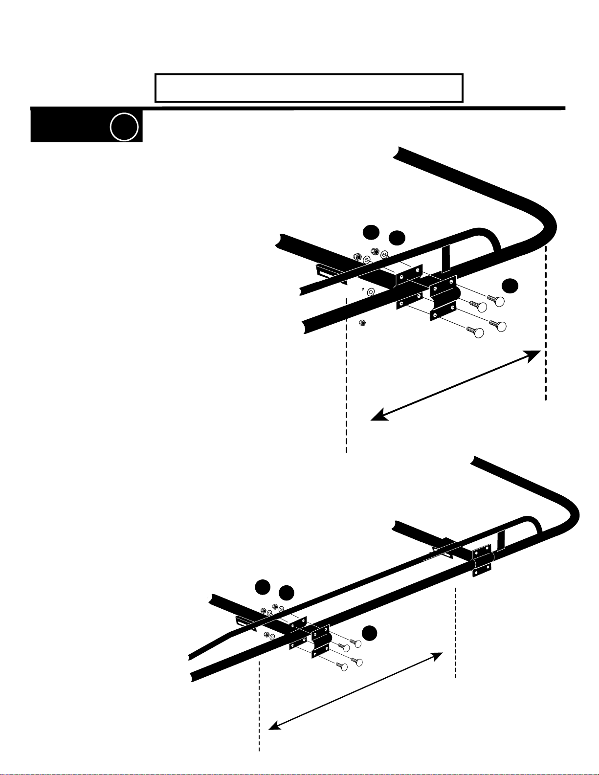
STEP 8
Ford Transit Connect
Rear Cross Bar
J
I
TMCS_3:1
#1 = Position centerline of rear crossbar about
36” forward of centerline of rear U-bar. Securely
bolt clamp plates together with bolts E,
flat washers I, and lock nuts J.
#2 = Position centerline of front crossbar about 39”
forward of centerline of rear crossbar. Loosely bolt
clamp plates together with bolts E, flat washer I and
lock nuts J.
E
36”
J
I
E
39”
Page 9
Ford Transit Connect, con’t
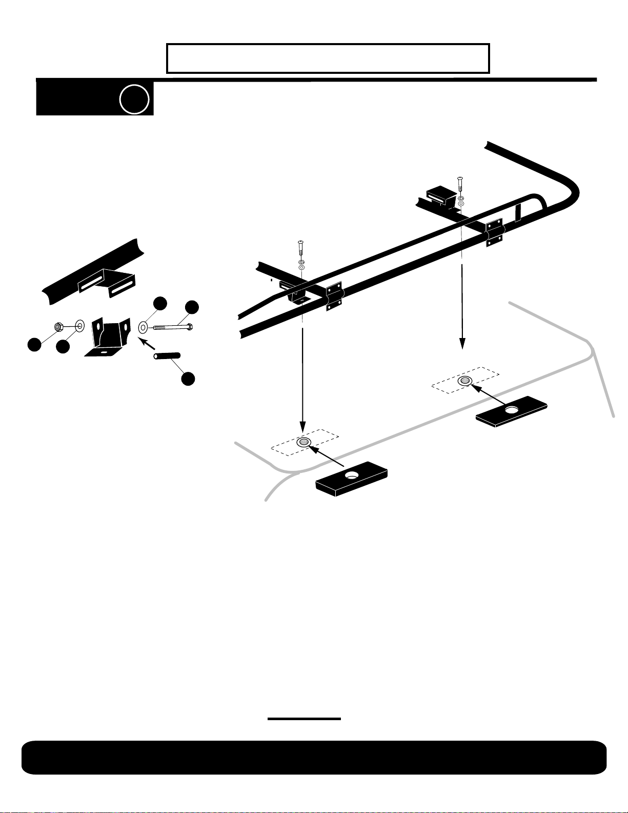
STEP 9
#1 = There are 8 mounting feet in your box,
SEE NEXT PAGE FOR DETAILS. There are 4 feet (these are
the shorter ones with no flange and a single hole in the bottom)
that will be used for Transit Connect installation.
NOTE: The front feet (these are the shortest ones, are angled
to conform with the contour of the front of the roof. There is a left
and a right front foot. See diagram next page. Find these now.
TMCS_3:1
L
M
L
#2 = Position the Transit Connect feet into the
slider brackets on the cross bars.
#3 = Place the spacer N inside the mounting
brackets. Loosely bolt the feet to slider brackets
using bolts
#4 = The Transit Connect has factory threaded
bosses on the roof. No need to drill holes in the roof.
These bosses have a threaded button with a rubber
washer. Remove the factory button and washer.
#5 = There are 4 rubber pads in the box. Align the
middle hole of the pad with the middle hole in the
Transit Connect foot. Cut off the ends of the pads to
match the width of the Transit Connect foot. Position
the pads over the threaded bosses.
K, washers L and lock nuts M.
K
N
Rear Pad
Front Pad
#6 = Carefully position the rack onto the roof. Align
the holes in the feet with the holes in the rubber pads
with the bosses. Loosely attach the rear feet to the
roof with M8 x 32 button head bolt, flat washer and
lock washer. Adjust the front cross bar as necessary.
To align the front feet. Securely attach the front feet
to the roof with M8 x 32 button head bolt, flat washer
and lock washer. Tighten rear feet.
Tighten down all nuts & bolts and
THAT'S IT! You are now ready to use your rack.
CAUTION! DO NOT OVERLOAD YOUR TRANSIT CONNECT.
Page 10
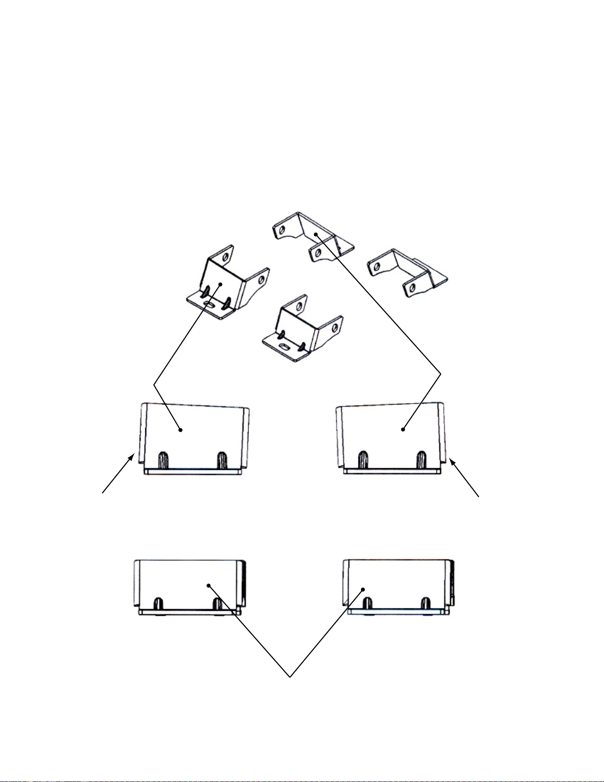
► Use these feet to mount to a Transit Connect.
► Cut the rubber pad to fit foot.
Front Drivers Side
Taller in Front
Front Passenger Side
Taller in Front
Rears’
Page 11
Ensure all nuts & bolts are tighten down and THAT'S IT! You are now ready to use your rack.
O
V
E
R
T
U
R
N
F
O
R
C
E
TMCS_3:1
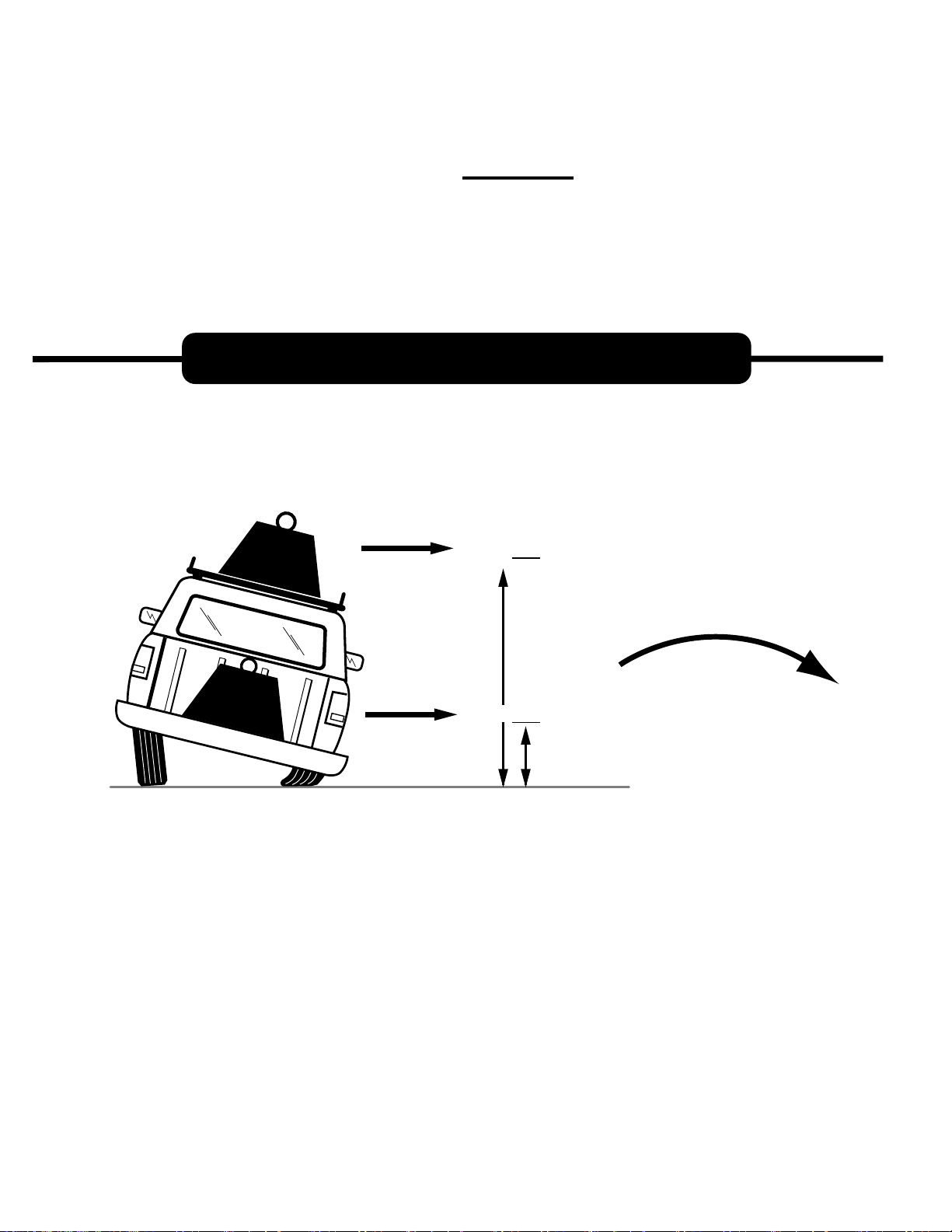
DON'T OVERLOAD YOUR VEHICLE!
@
100" = X3 lbs.
.SBL
SBL
.
WEIGHT CARRIED ABOVE THE FLOOR OF THE TRUCK BED (E.G. ON AN OVERHEAD TRUCK RACK)
WILL SIGNIFICANTLY INCREASE THE VEHICLE'S TENDENCY TO OVERTURN. ALWAYS KEEP
HEAVY LOADS EVENLY DISTRIBUTED AND AS LOW AS POSSIBLE. IT IS IMPORTANT TO NOTE
THAT THE KARGO MASTER RACK LOAD BEARING CAPACITY MAY BE GREATER THAN YOUR
TRUCK'S GAWR OR GVWR CAPACITY, AND IS PROBABLY GREATER THAN THE WEIGHT THAT
CAN BE SAFELY CARRIED OVERHEAD.
@
35" =
x1
lbs.
 Loading...