

Page 1
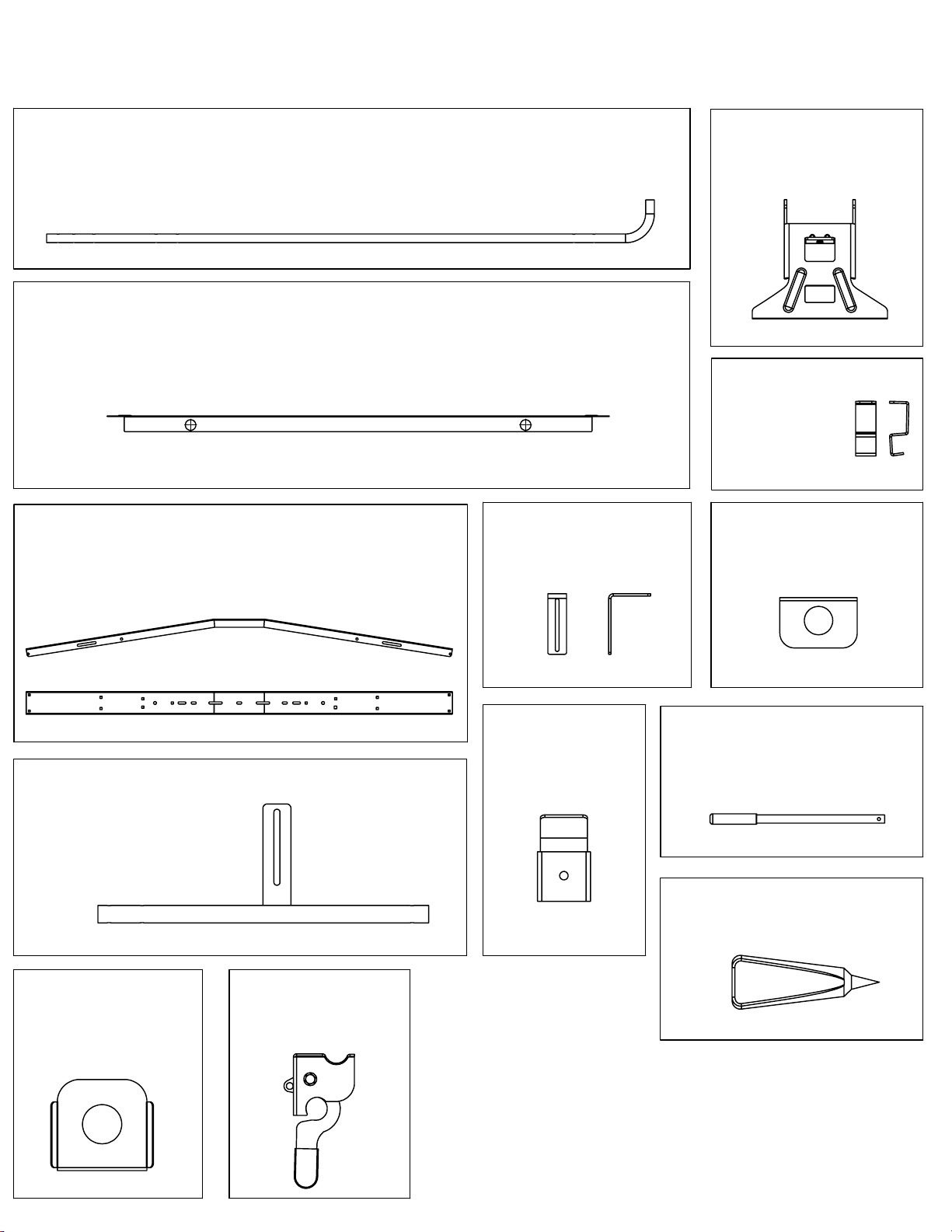
40803 Parts List
Side Tube Assembly
Cross Bow
Item -001
Qty 2
Item -012
Qty 1
Support Angle
Item -014
QTY 1
Pad Bracket
Item -026
QTY 1
Gutter Mount
Item -041
QTY 4
Gutter Clamp
Item -044
QTY 4
Bracket Plate
Item -015
QTY 1
Tube Assembly
Item -016
QTY 1
Load Lock Plate
Item -025
QTY 2
Lock Box Assembly
Item -002
QTY 1
Clamp Pads
Item -034
QTY 2
For TECHNICAL SUPPORT Call: 800-343-7486
Handle
Item -002
QTY 1
E-6000
QTY 1
E-6000
Page 2
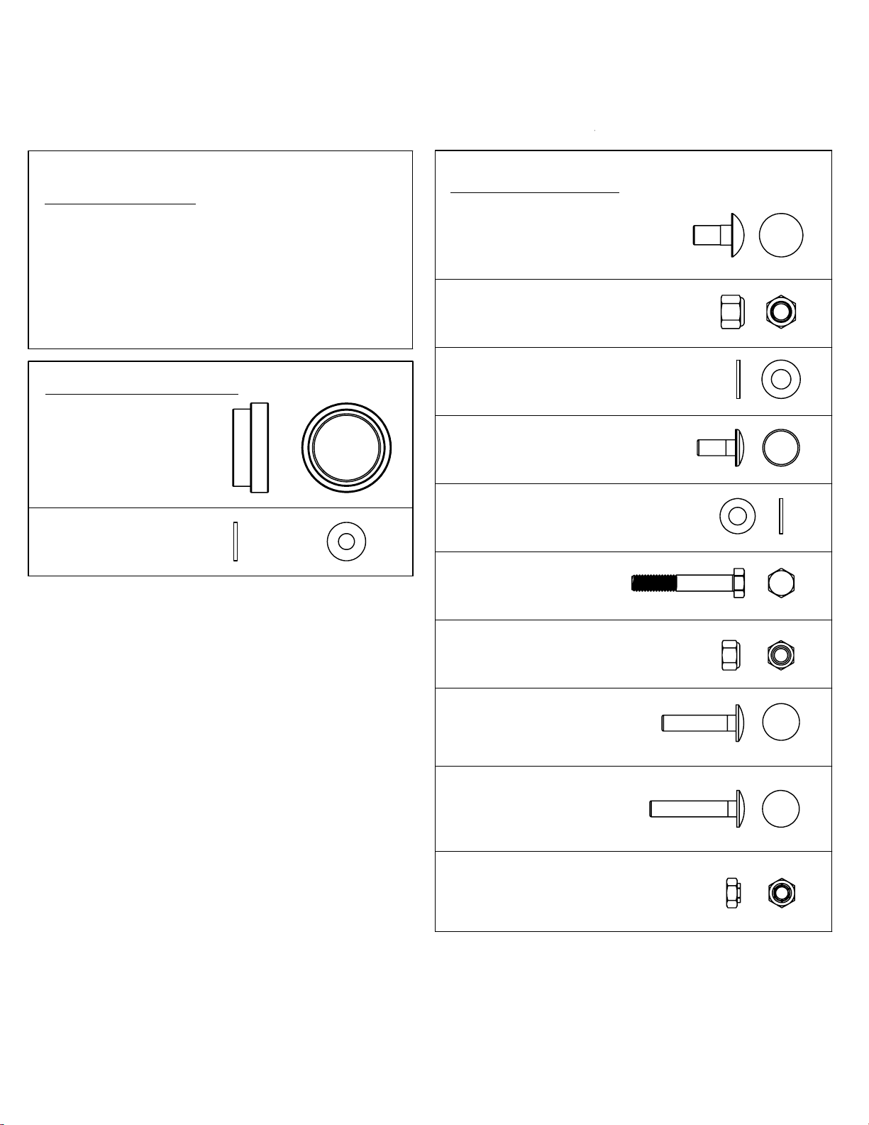
40803 Hardware List
Tools Needed
8' Tape Measure
1/2 Socket
9/16 Socket
Component Pack
Qty 2
Flange Bushing
Item -013
Qty 2
5/16 ID Nylon Washer
Item -038
1/2 End Wrench
9/16 End Wrench
Hammer
Hardware Pack
(a)
Qty 11 3/8-16 x 1 Carriage Bolt
(c)
Qty 13 3/8-16 Nylock Nut
(b)
Qty 13 3/8 Flat Washer
(f)
Qty 4 5/16 x 3/4 Carriage Bolt
(k)
Qty 24 5/16 Flat Washer
(g)
Qty 1 5/16 x 2 3/4 Hex Bolt
(h)
Qty 15
5/16 Nylock Nut
(u)
Qty 5 5/16 x 1 1/2 Carriage
Bolt
(v)
Qty 6 5/16 x 1 3/4 Carriage
Bolt
(w)
Qty. 1 5/16 Nylock Jam Nut
For TECHNICAL SUPPORT Call: 800-343-7486 Monday - Friday 8:00 A.M to 4:30 P.M. (PST)
Page 3
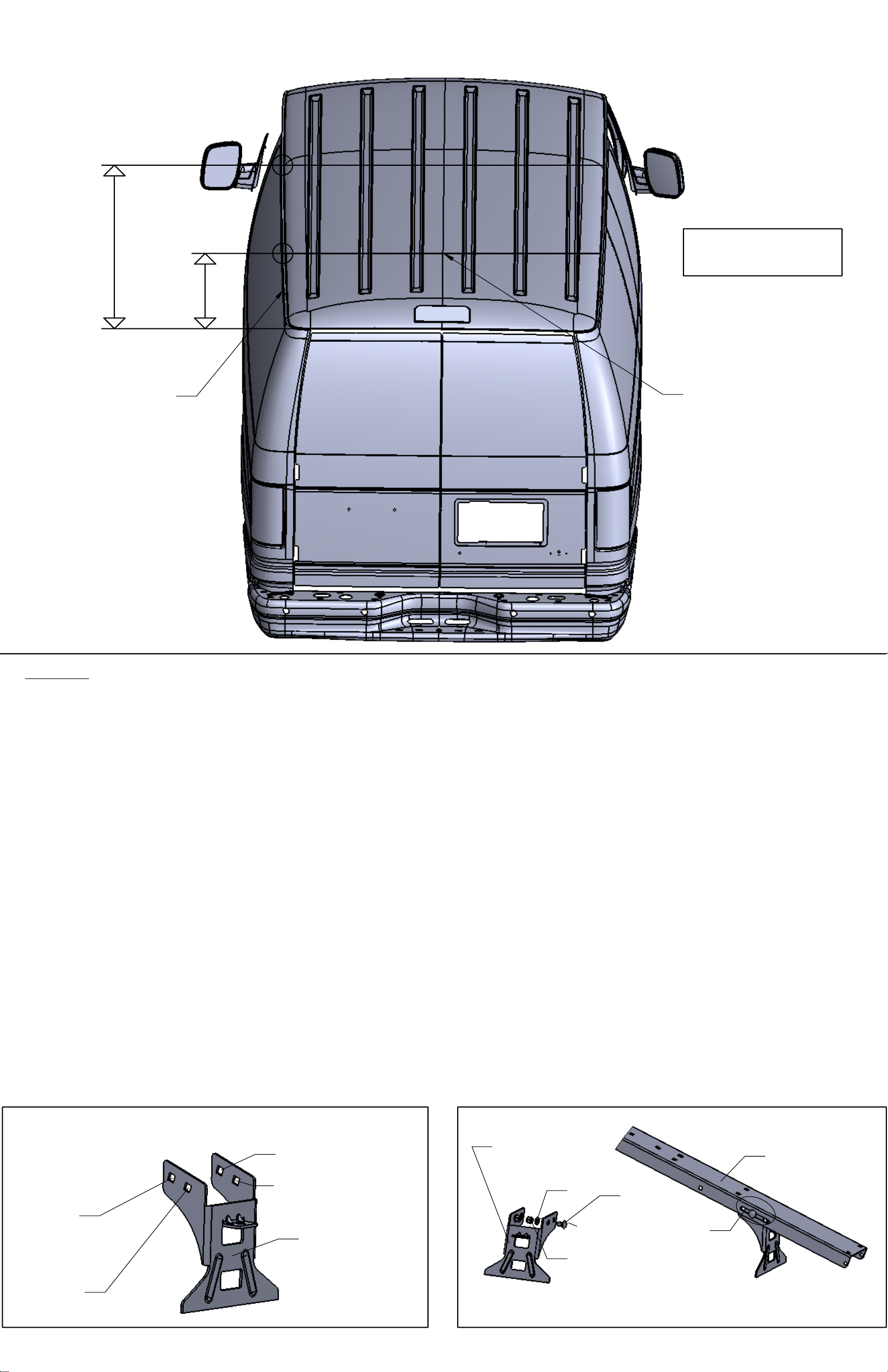
Approx
84"
DIAGRAM 1a
Approx
16"
Gutter Rail
Rear Door
Center Dimension
STEP 1
The first thing to decide is whether or not you will have the ability to lift and place the
entire assembled rack on the van. It will be easier to do the full assembly off the van.
But this will require 4 people, or a forklift, or a hoist. If not, you must assemble the rack
on top of the van.
When setting the cross bows in place on the van leave mounting clamp loose enough
for movement back and forth to align insertion of side tube assembly (-012).
Make (2) pencil marks
[Diagram 1a]
on gutter rail. One about 16" from rear of door
and one at 84". These will provide an approximate mount location for gutter mount
brackets (-041)
dimension. Insert mount (-041) into cross bow channel opening
[Diagram 6d]
. Now measure across gutters for approximate center
[Diagram 6c].
Insert 3/8
x 1 carriage bolt (a) from backside and through channel with 3/8 flat washer (b) and
3/8 nylock nut (c).
[Diagram 6d]
to correspond to gutter center measurement taken earlier. Hole "C" will
NOTE:
Choose hole "C"(FORD) or "D"(CHEVY) in bracket (-041) per
provide a maximum of 65" and a minimum of 59" (gutter centers). Hole "D" will provide
a maximum of 62 1/2" and a minimum of 57". Install all four (-041) brackets and leave
bolts loose for final adjustment on van.
If you are installing the rack yourself, place the bows and attached gutter mounts on
the van now.
DIAGRAM 6d
Max 65" / Min 59"
Max 62 1/4" / Min 57"
"C"
FORD
Gutter Mount
(-041)
"D"
CHEVY
Gutter Mount
(-041)
(b)
(c)
Cross Bow
(-001)
(a)
Channel
Opening
DIAGRAM 6c
Page 4
STEP 2
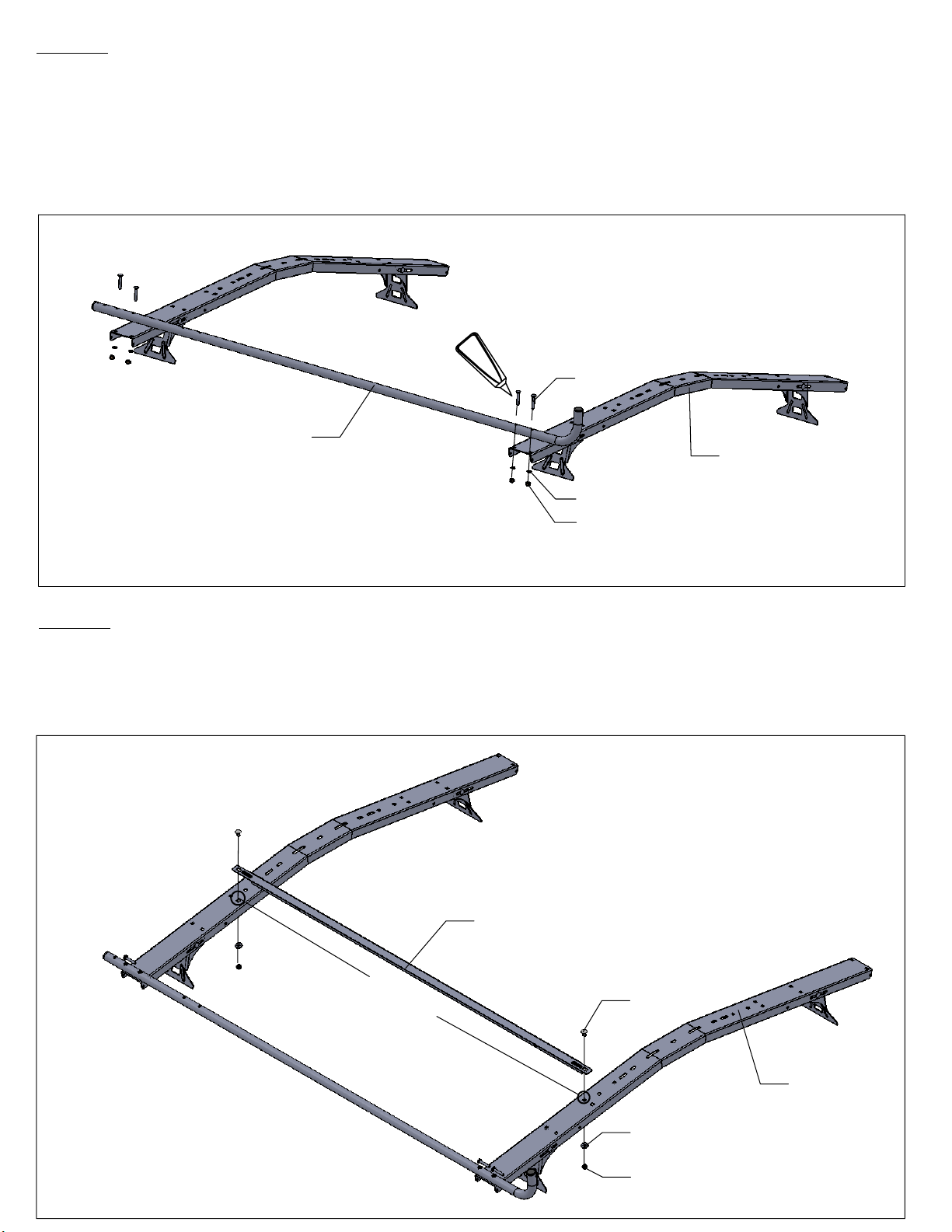
Install side tube (-012) per
[DIAGRAM 1b]
using 4 each 5/16 x 1 3/4 carriage bolts
(u), 4 each 5/16 flat washers (k) and 4 each 5/16 nylock nuts (h). Run bead
around the head of the button head bolts with E6000 sealer (supplied). (This will
prevent possible corrosion of the tube I.D. )There is 1 each of a 5/16 nylock jam
nut, a jam nut is thinner than the other nuts. Find it and set it aside for step 8
DIAGRAM 1b
E6000
(u)
Side Tube
(-012)
Cross Bow
(-001)
(k)
(h)
STEP 3
Install support angle (-014) per
(a), 2 each 3/8 flat washers and 2 each 3/8 nylock nuts (c). Install into third square
hole from the end of cross bow (-001).
[DIAGRAM 1c]
using 2 each 3/8 x 1 carriage bolts
DIAGRAM 1c
Support Angle
(-014)
Third Hole
(a)
(b)
(c)
Cross Bow
(-001)
Page 5
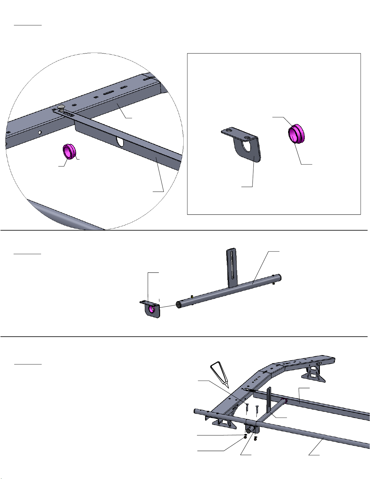
STEP 4
Next, insert bushing (-013) into support angle (-014) flange side in per
Next, insert bushing (-013) into bracket plate(-015) as shown in
[DIAGRAM 2b].
DIAGRAM 2a
DIAGRAM 2b
Cross Bow
Flange Side
Bushing
(-013)
Flange Side
(-001)
Support Angle
(-014)
Bracket Plate
(-015)
[DIAGRAM 2a].
Bushing
(-013)
STEP 5
Install bracket plate
(-015) with the
flange facing
outward onto tube
assemby (-016)
as shown.
STEP 6
Now install the end of tube
assembly (-016) into the bushing
on the support angle (-014).
Match up the holes in the bracket
plate (-015) to the holes in the side
tube (-012 ) and insert 2 each 5/16 x
1 3/4 carriage bolts (u), 2 each 5/16
flat washers (k) and 2 each 5/16
nylock nuts (h). Run a bead of E6000
around the head of the bolts.
Bracket
Plate (-015)
(u)
(k)
(h)
E6000
Tube Assembly
Tube Assembly
Bracket Plate
(-015)
(-016)
Angle Support
(-014)
(-016)
Side Tube
(-012)
Page 6
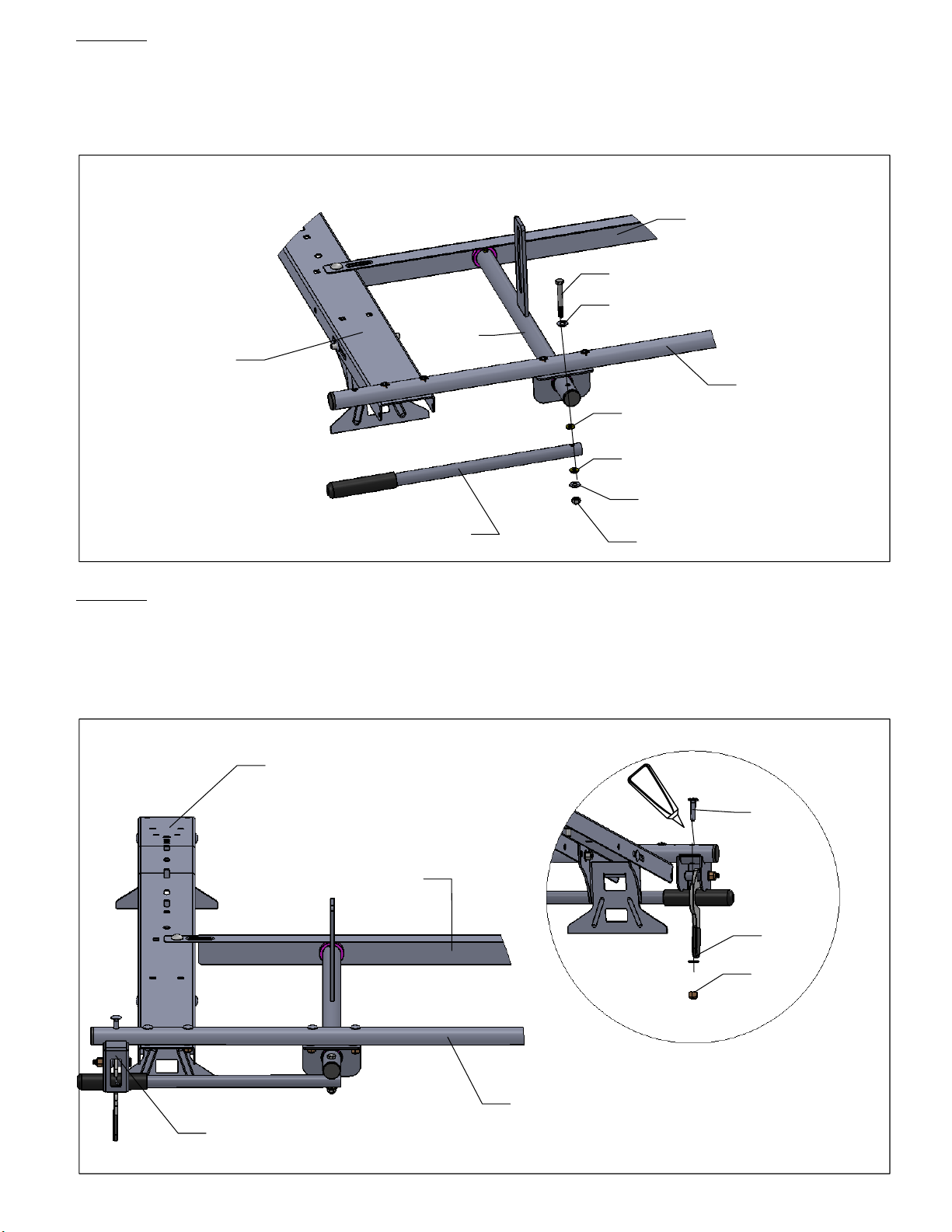
STEP 7
Next, install handle (-002) to the end of tube assembly (-016) using 1 each
5/16 x 2 3/4 hex bolt (g), 2 each nylon washers (-038), 2 each 5/16 flat washers
(k), 1 each 5/16 nylock nut (h). Note: insert washers (-038 ) over and under
handle tube (-002) per
[DIAGRAM 3]
. Tighten so handle rotates freely.
DIAGRAM 3
Support Angle
(-014)
(g)
Cross Bow
(-001)
Tube
Assembly
(-016)
(k)
(-038)
(-038)
Side Tube
(-012)
(k)
Handle
(-002)
(h)
STEP 8
Install the lock box assembly (-002) to the end of the side tube (-012) per
[DIAGRAM 4]
(k), 1 each 5/16 nylock jam nut (w). Run a bead around the bolt head with
E6000 as shown.
Using 1 each 5/16 x 1 1/2 carriage bolt (u), 1 each 5/16 washer
Cross Bow
(-001)
Angle Support
(-014)
E6000
(u)
(k)
Front View
Lock Box Assembly
(-002)
(w)
Rear View
Side Tube
(-012)
DIAGRAM 4
Page 7
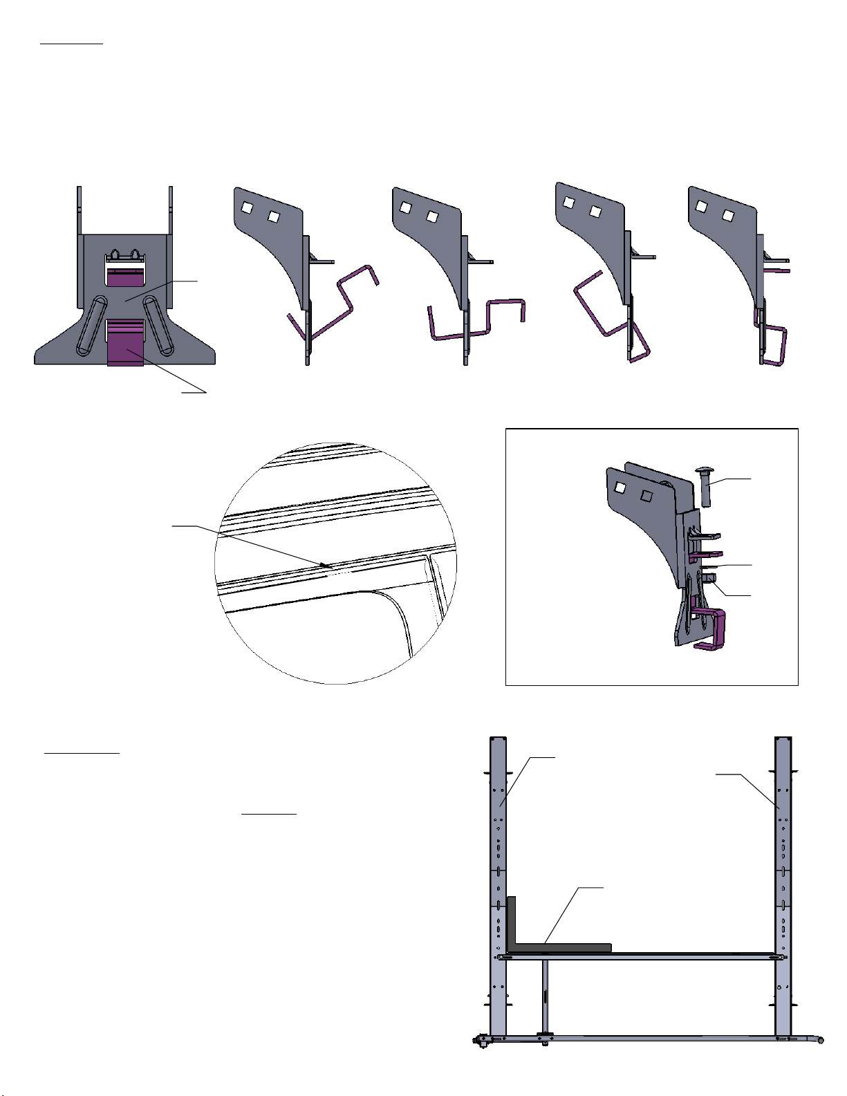
STEP 9
Now insert gutter clamp (-044) to mount (-041) per
[DIAGRAM 5]
. Align holes for
clamp bolt and use 4 each 5/16 x 1 1/2 carriage bolts (v), 4 each 5/16 flat washers
(k), 4 each 5/16 nylock nuts (h). Leave hardware loose for final adjustment on the
next step.
Gutter
Mount
(-041)
Gutter Clamp
(-044)
DIAGRAM 5
Seat Gutter
Clamp
Into Channel
Before
Tightening
STEP 10
If your rack was assembled off the van you
can now install it per
rack cross bows (-001) are square per
[DIAGRAM 5a]
before tightening bolts as
binding may occur if rack is out of square.
Make sure the gutter mount (-044) is properly
seated in rain gutter channel before
tightening gutter clamp (-041). Do not overtighten clamp. A torque rating of 150 inchpounds is suggested as deformation of
clamp and gutter may occur.
STEP 1
. Be certain the
Gutter
Mount
Assembly
Cross Bow
(-001)
(v)
(k)
(h)
Cross Bow
(-001)
Square
DIAGRAM 5a
Page 8
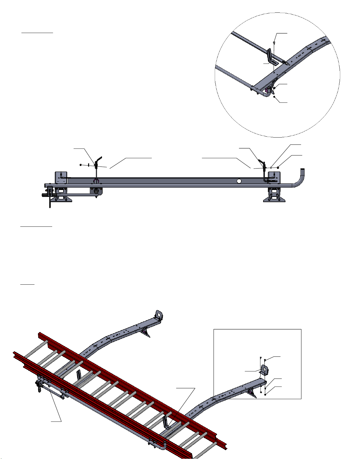
STEP 11
Install pad bracket (-026) using 1 each 3/8 x 1
carriage bolt (a), 1each 3/8 flat washer (b), 1
each 3/8 nylock nut (c) shown in
Do not tighten for later adjustment.
Now install the clamp pads (-034) to pad
bracket (-026) and tube assembly (-020) per
[DIAGRAM 7a]
using 2 each 3/8 washers (b)
and 2 each 3/8 nylock nuts (c). Do not tighten.
[DIAGRAM 7]
.
(a)
Pad Bracket
(-026)
(b)
(c)
DIAGRAM 7
Tube Assemby
(-020)
Clamp Pads
(-034)
Pad Bracket
(-026)
(b)
(c)
DIAGRAM 7a
STEP 12
Now install ladder into desired position with ladder rung firmly against the clamp
pads. Now adjust front pad bracket (-026) firmly against rung. It may be
necessary to move pad bracket (-026)to align with one of the two square holes
in the cross bow. Note: position pad bracket (-026) so adequate pressure is
applied to ladder rung when rotating handle (-002). Ladder should be clamped
firm
with no movement when handle is in lock position. Tighten all hardware.
You may want to install load lock plate (-025) using 4 each 5/16 x 3/4 carriage
bolts (f), 4 each 5/16 flat washers (k), and 4 each 5/16 nylock nuts (h) per
[DIAGRAM 8].
Handle
(-002)
Pad Bracket
(-026)
DIAGRAM 8
Load Lock
Plate
(-025)
(a)
(k)
(h)
For TECHNICAL SUPPORT Call: 800-343-7486
 Loading...