

Page 1
O
V
E
R
T
U
R
N
F
O
R
C
E
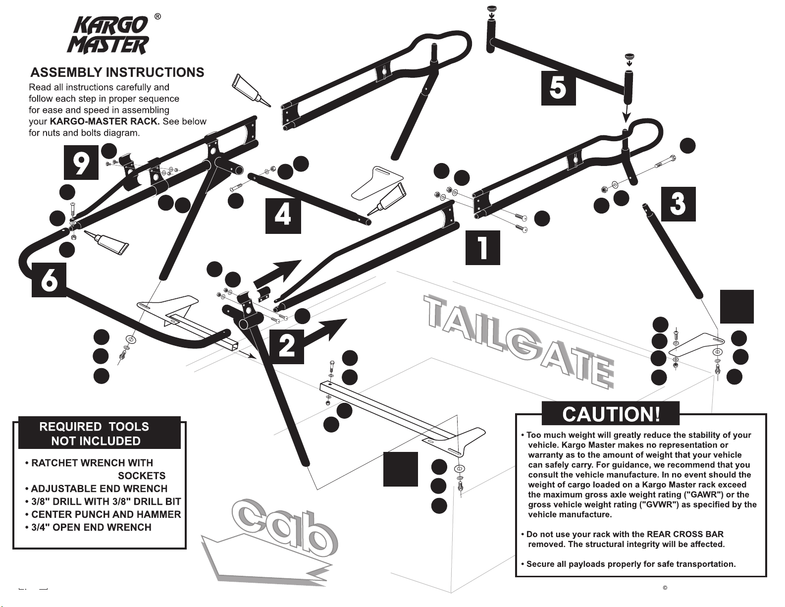
ASSEMBLY INSTRUCTIONS
for :
PRO-III KS
®
(916) 638-8703
• 11253- G Trade Center Drive • Rancho Cordova, CA 95742 •
(800) 343-7486
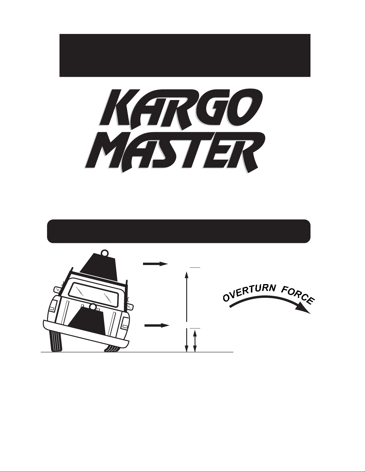
DON'T OVERLOAD YOUR VEHICLE!
LBS.
LBS.
@
@
WEIGHT CARRIED ABOVE THE FLOOR OF THE TRUCK BED (E.G. ON AN OVERHEAD TRUCK RACK)
WILL SIGNIFICANTLY INCREASE THE VEHICLE'S TENDENCY TO OVERTURN. ALWAYS KEEP
HEAVY LOADS EVENLY DISTRIBUTED AND AS LOW AS POSSIBLE. IT IS IMPORTANT TO NOTE THAT
THE KARGO MASTER RACK LOAD BEARING CAPACITY OF 1000 LBS. MAY BE GREATER THAN YOUR
TRUCK'S GAWR OR GVWR CAPACITY, AND IS PROBABLY GREATER THAN THE WEIGHT THAT CAN BE
SAFELY CARRIED OVERHEAD.
100" = 3X lbs.
35" =
X lbs.
For TECHNICAL SUPPORT Call:
1.800.343.7486
HOURS: Monday- Friday 8:00 A.M. to 4:30 P.M. ( PACIFIC )
Page 2
PRO - III KS
S
I
L
I
C
O
N
E
R
B
G
M
K
E
N
O
C
I
L
I
K
N
E
S
4
S
I
L
I
C
O
N
E
L
N
K
1
J
N
F
C
3
N
K
7
F
77
D
H
O
A
2
C
J
J
J
M
H
O
A
J
M
1/2", 9/16", & 3/4"
r
w
a
you
fo
d
t
i
r
com
88
8
H
O
A
2006 KargoMaster-'Pro 3-KS'_1.1
Page 3
A
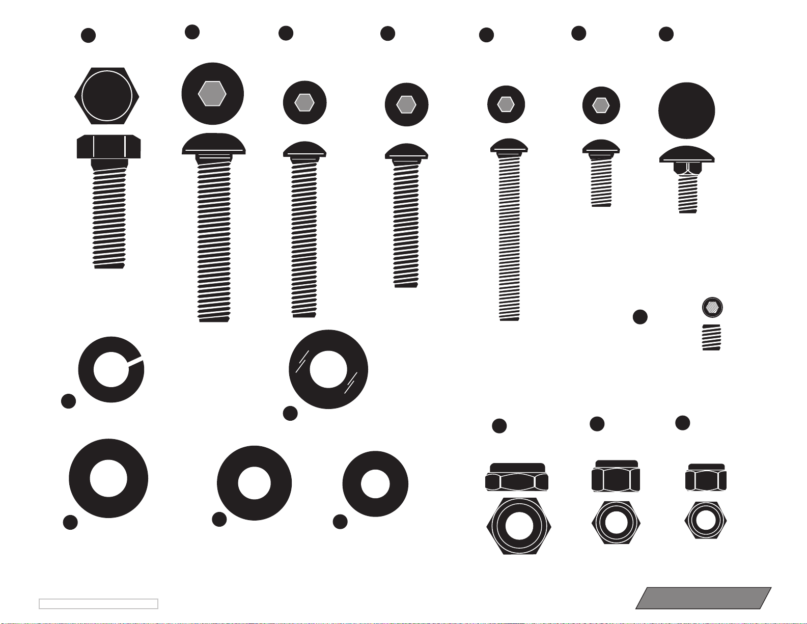
(4 ea.)
1/2" x 1 1/2"
Hex Bolt
B
(2 ea.)
1/2" x 2 1/4"
Button Head Bolt
(3 ea.)
C
3/8" x 2 1/4"
Button Head
(8 ea.)
D
3/8" x 1 3/4"
Button Head
(2 ea.)
E
5/16" x 2 1/4"
Button Head Bolt
(8 ea.)
F
5/16" x 3/4"
Button Head Bolt
(4 ea.)
G
5/16" x 3/4"
Carriage Bolt
(4 ea.)
P
5/16" x 3/8"
Allen Head Set Screw
O
(4 ea.)
1/2" Lock Washer
H
( 6 ea.) 1/2" SAE Flat Washer
©2006 KARGO MASTER --Pro 3-KS _1.1
R
(2 ea.) 1/2" Rubber Washer
J
(22 ea.) 3/8" SAE Flat Washer
K
(14 ea.) 5/16" Flat Washer
L
(2 ea.)
1/2" Jam Nut
N
M
(11 ea.)
3/8" Lock Nut 5/16" Lock Nut
Shown Actual Size
Shown Actual Size
(14 ea.)
Page 4
Pro 3KS_1.1-’06
STEP 1
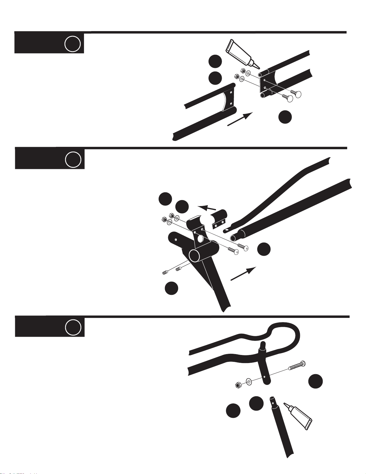
#1 = Cover and seal swedge joints with silicone
sealant and join FRONT and REAR side channels
together, there is a LEFT & RIGHT FRONT, with
the Right marked with a GREEN dot on the
overlapping plate. There is a RIGHT & LEFT
REAR. The leg cups angle outward. Be sure the
connecting plates overlap, and bolt together with
bolts G, washers K and lock nuts N.
STEP 2
#1 = Slide the FRONT leg onto the front side
channel. There is a RIGHT & a LEFT.
Match to the correct side channel so that both
FRONT & REAR legs angle outward.
Insert the set screws P, but do not tighten yet.
N
K
N
K
S
I
L
I
C
O
N
E
G
#2 = Loosely attach the top CLAMP with
bolts F, washers K, and nuts N.
#3 = Final positioning of the front legs will
follow in STEP 8.
STEP 3
#1 = Cover and seal swedge joints with
silicone sealant and attach the REAR LEGS
with bolts C, washers J, and nuts M.
Note: The distance between front & rear
legs will not be longer than the inside
measurements of the bed itself.
P
M
J
F
(RIGHT SIDE SHOWN)
C
S
I
L
I
C
O
N
E
Page 5
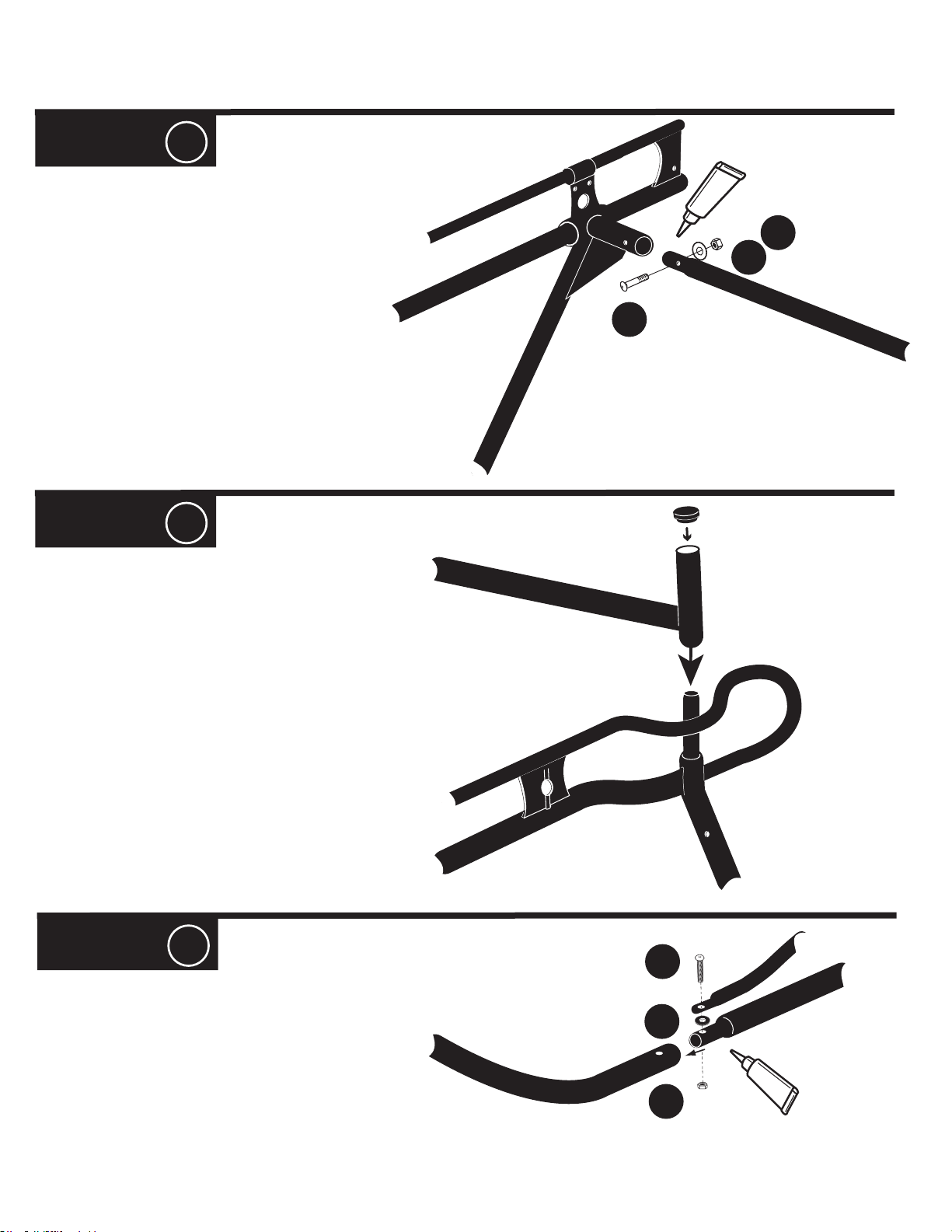
STEP 4
#1 = Cover and seal swedge joints with
silicone sealant and insert the CENTER
CROSS BAR into the SIDE RAIL CUPS
and attach with bolts E, washers K and
lock nuts N.
E
Pro 3-ks_1.1-’06
E
N
O
C
I
L
I
S
N
K
STEP 5
#1 = Insert PLASTIC CAPS onto the rear
crossbar uprights, (the tall side of the tube).
Slide the REAR CROSS BAR into the REAR
LEG POSTS at the top, as shown.
STEP 6
B
#1 = Cover and seal swedge joints with
silicone sealant and slide FRONT CROSS
BAR onto side rails and bolt together with
bolts B, rubber washer R, and jam nut L.
R
L
S
I
L
I
C
O
N
E
Page 6
Pro 3-KS_1.1 -12’06
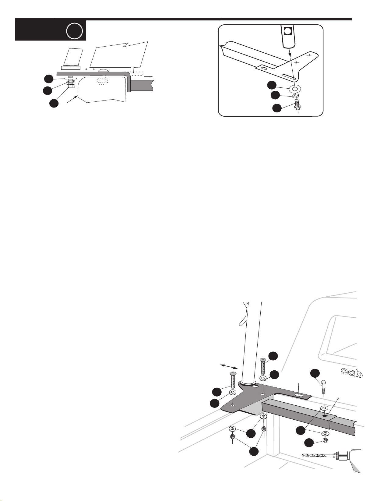
STEP 7
CAMPER SHELL
01
H
H
O
A
Outside of
Truck Bed
#1 = Remove your camper shell from truck. Note whether or not there is a ridge on the bottom of your shell.
REAR VIEW OF TRUCK
O
A
#2 = The Front Mounting Plates have support arms. Slide one Arm into the other. Position the Front Mounting Plates
assembly as far forward as possible, with the Mounting Plate tongue over the front bulkhead of the truck bed. Slide the Front
Mount Plates apart so that they are flush against opposite sides of the truck bed. Measure the inside dimension of the Mount
Plates just above the Support Bar, and the outside dimension of the ridges (if any) on the bottom of your shell. It may be
necessary to notch this ridge to avoid interference with the Mount Plates. Position the Rear Mount Plates as far back as
possible on the truck bed rail, but do not overhang the tail gate.
NOTE: Measure the distance between the center of the slot in the right front Mount Plate to the center of the slot in
the right rear Mount Plate. Make certain distance is the same on the left side.
You may wish to notch the ridge of the camper shell (if any) front and back so that the Mount Plates can be slid in towards
the center of the truck bed to minimize overhang.
Note: If you choose to minimize overhang, be absolutely certain that the distance from the outside of the slot in the
right plate to the outside slot of the left plate is at least 67.5”.
#3 = With the Mount Plates in their final position, locate and mark two optimal bolt hole locations on the top of each Mount
Plate. The bolts should be located as far apart as possible, with clear access to the bolt and nut underneath the truck's bed
rail. If the inside of your truck bed has a double wall and it is not possible to locate a bolt on the Mounting Plate near the leg,
we recommend using our accessory STAKE POCKET "T" BOLTS to provide an additional attachment point. With the
Front Mount Plates in their final location, mark the through bolt hole in the inner Support Arm.
#4 = Remove Rack from the truck. Punch hole centers in the
locations that you have marked, and drill 2x 3/8" holes in each Mount
Plate and in the inner Support Arm.
#5 = Bolt the Support Arms together using bolt C , Flat washer
J, and lock nut M.
#6 = Set the Mount Plates back on the truck, in exactly the
same location that they were before. Make certain that the Mount
Plate is square with the bed rail. We recommend that you clamp
each foot plate in position before drilling through the truck's bed
rail. CHECK TWICE - DRILL ONCE!
D
J
D
J
BULKHEAD
C
THROUGH
BOLT HOLE
#7 = Apply adhesive foam tape (NOT INCLUDED) to seal the
gaps between the foot plates and the camper shell along the
bed rail and bulk head. Attach the camper shell to the truck.
INSIDE BED WALL
J
M
J
M
3" 8
3/8"
Page 7
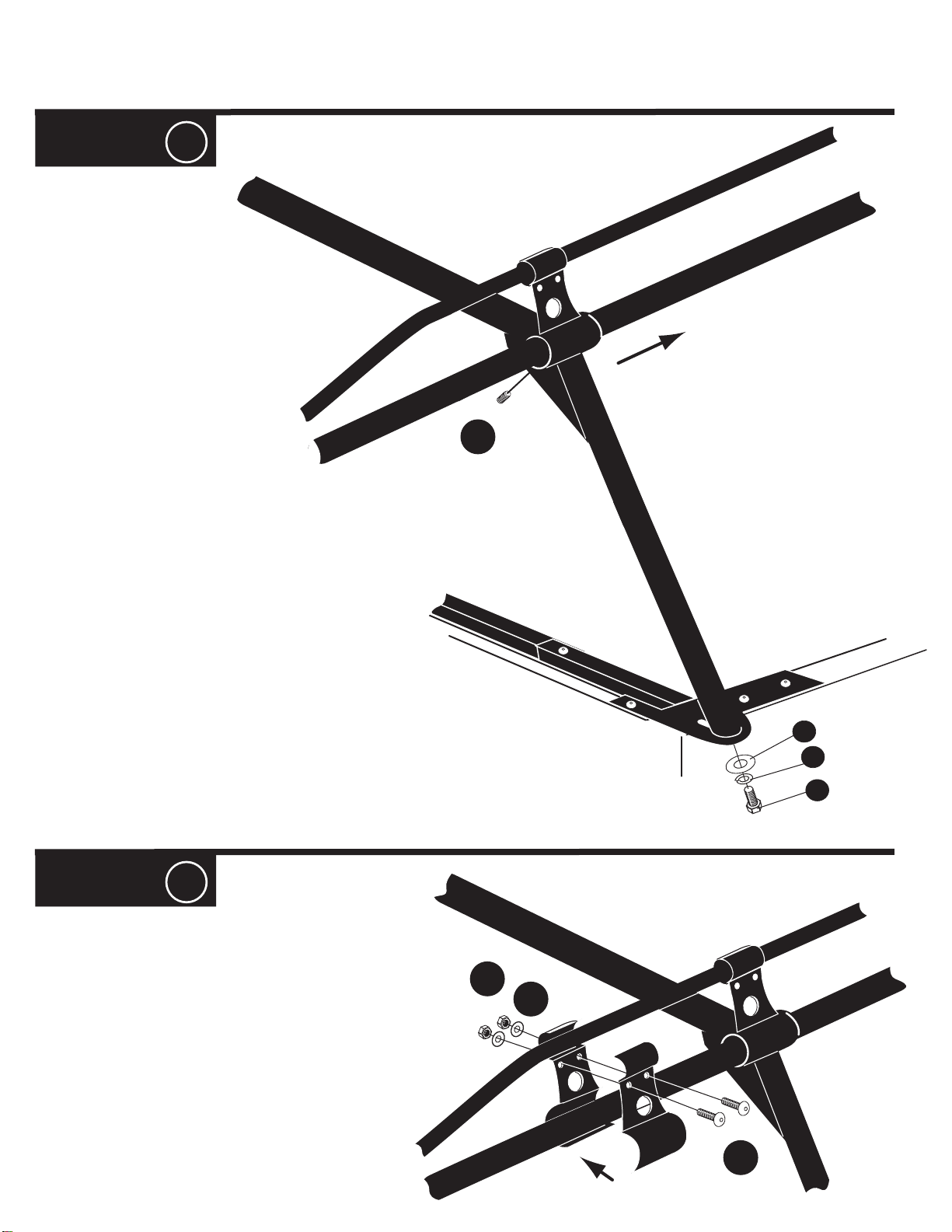
STEP 8
#1 = Adjust the position of the front legs of the
rack so that distance between the center of the
front legs and the center of the back legs is equal
to the distance between the center of the Mount
Plate slots as determined in # 2 above.
Tighten the set screws P in the barrel of each front
leg, and tighten Top Clamp nuts N. Place the rack
on the Mount Plates, center, and attach rack to
Mount Plates using bolts A, lock washers O and
flat washers H.
Pro 3-KS_1.1-12’06
P
STEP 9
#1 = Attach the front SUPPORT
UPRIGHT where the 1” tube begins
to bend downward, then...
TIGHTEN DOWN EVERYTHING AND....
THAT’S IT!
You’re ready to LOAD & GO!
H
O
A
N
K
G
Page 8
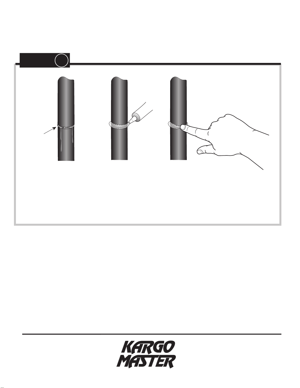
STEP 10
(WITHOUT SEALANT)
Rusty Joint
Apply a healthy air tight bead of silicone around every swaged joint to prevent
moisture from leaking into and out of the joint. If this is not done properly, the
inside surface of the tubes can rust and rusty water can leak out. Maintain this
SILICONE
SEALANT
joint seal throughout the life of your rack.
For TECHNICAL SUPPORT Call:
1.800.343.7486
HOURS: Monday- Friday 8:00 A.M. to 4:30 P.M. ( PACIFIC )
 Loading...