

Kalmar TL2 Maintenance Manual
Terminal Tractor
Kalmar TL2
2018
All variants
Maintenance Manual
Original Instructions


A Foreword
B Safety
C Preventive maintenance
0 Complete machine
1 Engine
2 Transmission
Maintenance
manual
3 Driveline/axle
4 Brakes
5 Steering
6 Suspension
7 Load handling
8 Control system
9 Frame, body, cab and accessories
10 Common hydraulics
11 Common electrics
12 Common pneumatics
D Error codes
E Schematics
F Technical data
G Appendixes


1
Table of content
A Foreword 3
Feedback 3
Maintenance manual 4
Reading this manual 7
TL2 Maintenance Manual
591 003 Default

2
TL2 Maintenance Manual
591 003 Default

A Foreword – Feedback 3
A Foreword
Feedback
Form for giving feedback
It is the goal of Cargotec Oy, to provide everyone working with the
maintenance of Kalmar machines with access to the correct infor‐
mation for performing the work safely and efficiently.
Your feedback is important for us to be able to improve the informa‐
tion.
Copy this form, write down your views, and send the form to us.
Thank you for your participation!
To: Cargotec Finland Oy
After sales, technical support / Terminal tractors
P.O. Box 387
FI-33101 Tampere
FINLAND
From: Company / sender: ..............................................................................................................................
Telephone: ..........................................................................................................................................
E-mail: .................................................................................................................................................
Date: .................................... - .................. - ..................
Manual
information
Suggestions,
comments,
remarks, etc.
Name / publication number: ................................................................................................................
Section / page number: ......................................................................................................................
..............................................................................................................................................................
..............................................................................................................................................................
..............................................................................................................................................................
..............................................................................................................................................................
..............................................................................................................................................................
..............................................................................................................................................................
TL2 Maintenance Manual
591 003 Default

4 A Foreword – Maintenance manual
Maintenance manual
General
The maintenance manual introduces the machine's maintenance
programme and items to the service personnel.
The manual provides instructions for the service personnel concern‐
ing safe working methods when servicing and adjusting the machine
according to the maintenance programme.
Support from our professional maintenance organisation and follow‐
ing the maintenance instructions described in the manuals are a
prerequisite for safe, reliable, and efficient operation of the machine
throughout its lifecycle.
Contact your superior if some parts of this manual lead to questions
or some important information of maintenance seems to be missing.
Contents
This maintenance manual contains the following information:
A Foreword General information about the purpose and contents of this maintenance
manual, instructions for reading the manual, and a form for giving feedback
B Safety Information regarding safety
C Preventive maintenance Information about preventive maintenance
Maintenance programme
0 Location of faults The adjacent sections include a description of the machine structure and
functions and some general instructions for locating the faults. All subjects in
1 Engine
2 Transmission
3 Driveline/Axle
4 Brakes
5 Steering
6 Suspension and wheels
7 Load handling
8 Control system
9 Frame, body, cab and accessories
the sections are listed in the following order:
the instructions for the service measures defined in the maintenance
1.
programme
ffunction-specific troubleshooting instructions
2.
technical information concerning maintenance work
3.
In addition to the general description of the machine operation, the manual
contains a detailed description of the operation of the maintenance item.
The sections describe the components related to the function in question. For
this reason, the most common components are mentioned in several
sections, but they are usually described in connection with the first function to
which the component is related.
If the function uses a component that has been described above, the
component is presented with a description relevant to the new function only.
10 Common hydraulics
11 Common electrics
12 Common pneumatics
TL2 Maintenance Manual
591 003 Default

D Error codes Error codes and instructions for reading the data
E Diagrams Electric, hydraulic, and pneumatic diagrams
F Specifications Technical specifications, conversion tables and unit conversion factors
G Terminology and index General terms and abbreviations, their explanations, and an index of
A Foreword – Maintenance manual 5
headings
Division into function groups
The above division of the maintenance manual into function groups
is the same for all machines manufactured by Cargotec Oy. The
groups are indicated by numbers with two digits (for example, 4.3
Power-assisted brake system). Machine specific adaptations of the
function groups are indicated by a third or fourth digit (for example,
4.3.9 Wheel brake or 4.3.9.1 Disc brake).
Certain headings (function groups) are omitted in the documentation
for certain machines if the machine lacks that particular function.
This means that there may be gaps in the function group number‐
ing, for example, 2.7 Cooling system may be included for certain
machines, but may be missing for other machines.
References between different manuals are used since the different
manual types have different purposes and thus different information
content.
References between sections within this maintenance manual are
indicated with the section and chapter number, for example, "See
section 4,
the same section is indicated by the page number, for example,
"
See Description of the fuel sensor on page 24
Brakes
, chapter 4.3.9.,
Wheel brake
". A reference within
".
Conditions
The maintenance instructions described in this manual are based
on the use of generally available standard tools. All lifting devices
required in the maintenance work, for example, slings, straps, and
ratchet blocks, must meet the national standards and regulations for
lifting devices.
Cargotec Oy, will not accept any responsibility for modifications per‐
formed without permission from the manufacturer, or if lifting devi‐
ces, tools, or work methods other than those described in this man‐
ual are used.
Storage
Keep this manual in good condition, and store it in a place where it
is always available to the service personnel.
About the machine
The information in this manual corresponds to the design and
appearance of the machine at the time of delivery. Information in the
manuals of the same machine type can differ from each other
depending on the machine that the customer has ordered.
TL2 Maintenance Manual
591 003 Default

6 A Foreword – Maintenance manual
All information and data in this manual are valid at the time of publi‐
cation.
Copyright
This document may not be copied, presented, or delivered to a third
party without our explicit permission, or used for purposes other
than those allowed by us.
We reserve the right to alter the adjustment values, equipment, and
service and repair instructions for the machine without prior notice.
Cargotec Oy
TL2 Maintenance Manual
591 003 Default
A Foreword – Reading this manual 7
Reading this manual
Information on possible safety hazards
This manual includes three types of warnings containing instructions
on how to avoid situations that may compromise safety.
DANGER
Warns about a situation that involves an immediate risk of personal
injury or death unless the safety instructions provided are observed.
WARNING
Warns about a situation that may cause personal injury, death,
and/or substantial damage to the machine or other property unless
the safety instructions provided are observed.
Fig. : This symbol indicates an accessory or optional
equipment.
CAUTION
Warns of a situation that may cause moderate personal injury
and/or damage to the product or other property unless the safety
instructions provided are observed.
Important information
The word NOTE is used to emphasise issues concerning safety or
the maintenance instructions to which special attention must be paid
while working on the machine.
An example of how the word NOTE appears is presented below.
NOTE
Calls the reader's attention to an instruction that, for example, empha‐
sises operational safety.
Optional equipment
The machine can be equipped with various accessories or optional
equipment. The equipment is marked with the symbol seen on the
left. The symbol is always accompanied with text representing and/
or describing the equipment.
The NOTE symbol is clearly distinguished from the text, and it is
placed next to the text and picture representing the equipment.
TL2 Maintenance Manual
591 003 Default
8
A Foreword – Reading this manual
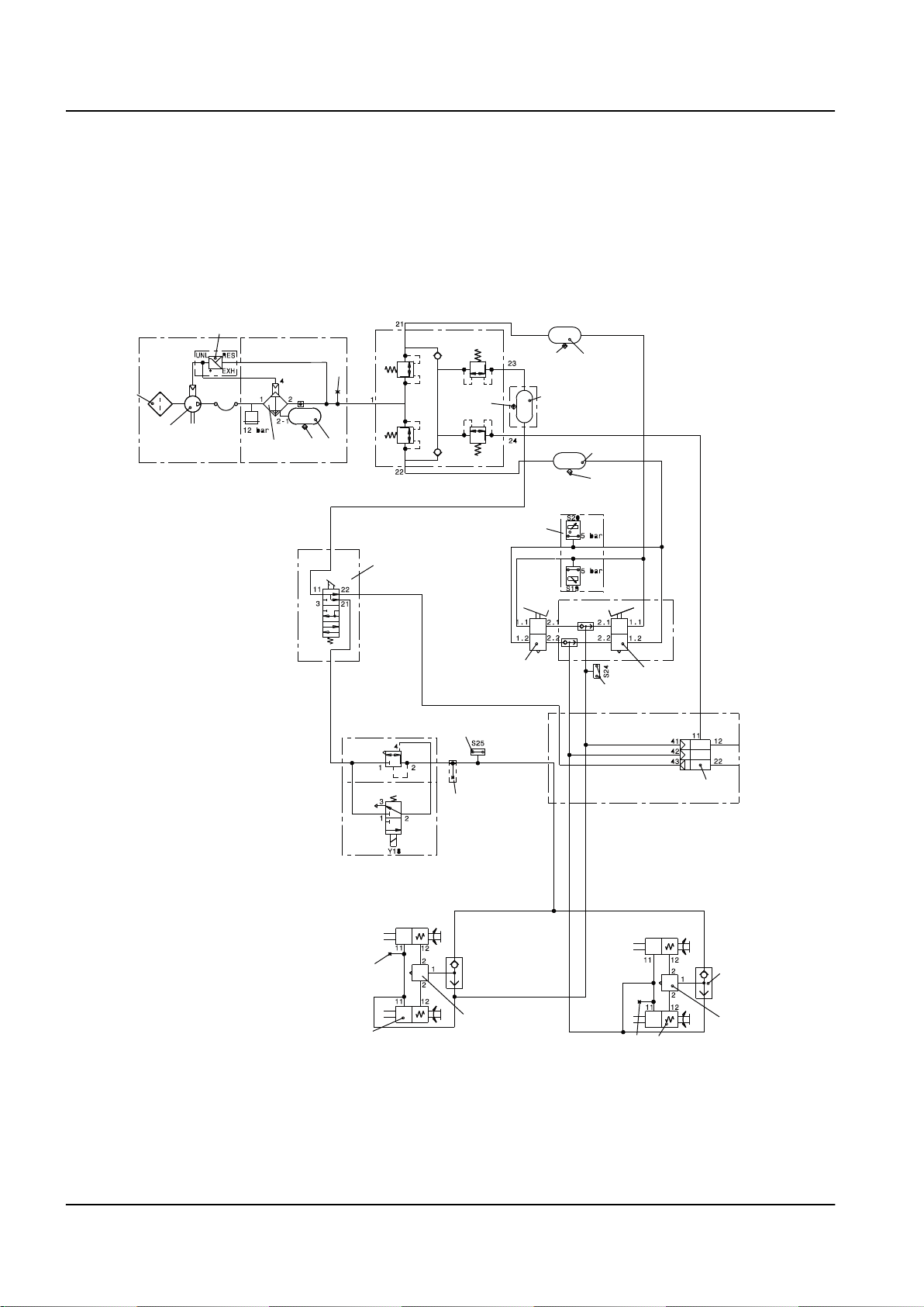
Function descriptions
The function descriptions are presented as circuit diagrams and
equipment position drawings that describe the function and the
associated components.
The function descriptions describe the function in a logical order.
The circuit diagrams use symbols to depict components such as
pumps, filters, valves, and sensors.
An example of a circuit diagram is provided on the following page.
3
6
1
8
7
9
7
69
2
3.1
7
9
4
7
10B
68
7
11
11B
12
14
60
64B
65
59
19
16
18
Circuit diagram component list
1. Terminal tractor air filter
2. Pneumatic air compressor
3. Pressure regulator
TL2 Maintenance Manual
591 003 Default
19
17
15
16

A Foreword – Reading this manual 9
3.1 Air drier
4. Air drier water separator container (6 litres)
6. Charging valve that fills the pneumatic system with compressed
air if the engine is not working or the compressor cannot be used
7. Drain valve
8. Four-circuit protection valve
9. Air tanks (2 x 30 litres)
10B. Pressure switch and measurement sensor
The measurement sensor is available as an option.
11. Front pedal valve
11B. The rear pedal valve and shuttle valve in tractors equipped
with a revolving seat
12. Brake light switch
14. Parking brake indicator light switch
15. Shuttle valve
16. Brake pressure quick release valve
17. Rear axle brakes and parking brake spring chamber
18. Front axle brakes
The parking brake spring chamber is an option.
19. Pressure measurement fitting
59. Parking brake solenoid valve
60. Parking brake relay valve
64B. Trailer brake control valve for the EC-compliant brake system
65. Parking brake release
68. Parking brake valve for the EC-compliant brake system
69. Air tank (30 litres) for the EC-compliant brake system
TL2 Maintenance Manual
591 003 Default
10 A Foreword – Reading this manual
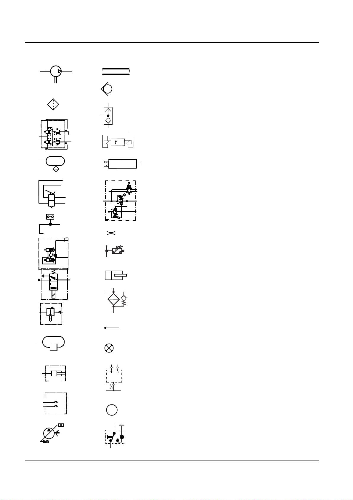
Explanation of the function description symbols
1
14
The following symbols are used in function descriptions. The sym‐
bols are based on standard symbols used in the electric and
hydraulic diagrams.
15
Pneumatic air compressor
2
16
3
a
17
4
5
18
19
b
A
B
6
20
7
21
22
8
23
1.
Air filter
2.
Four-circuit protection valve in the pneumatic system
3.
Air tank
4.
Brake pedal valve in the pneumatic system
5.
Pressure switch in the pneumatic system
6.
Service brake and parking brake chamber in the pneumatic
7.
system
Solenoid valve in the pneumatic system
8.
Level valve in the pneumatic system
9.
Air spring in the pneumatic system
10.
Cylinder in the pneumatic system
11.
Palm type couplings in the pneumatic system
12.
Variable-displacement pump in the hydraulic system
13.
Pressure/return line in the hydraulic system
14.
Throttle valve in the hydraulic system
15.
Pressure-controlled shuttle valve in the hydraulic system
16.
Electrically controlled solenoid valve in the hydraulic system
17.
Electrically controlled directional valve in the hydraulic system
18.
Load control valve in the hydraulic system
19.
Throttle valve in the hydraulic system
20.
Pressure switch in the hydraulic system
21.
Cylinder in the hydraulic system
22.
Return filter in the hydraulic system
23.
Cable in the electric system
24.
Indicator light in the electric system
25.
Level sensor in the electric system
26.
Electric motor
27.
Control switch in the electric system
28.
9
10
11
13
12
24
25
26
27
28
M
TL2 Maintenance Manual
591 003 Default

A Foreword – Reading this manual 11
Manual package
The following manuals are included in the machine delivery as
ordered:
Operator's manual
•
Maintenance manual
•
Spare parts catalogue
•
Each manual can be ordered separately, in case extra copies of
instruction manuals or spare parts catalogue for the machine are
needed later.
Ordering the manuals
The manuals can be ordered from the manufacturer's spare parts
department.
Refer to the serial number of the machine when placing the order.
TL2 Maintenance Manual
591 003 Default

12 A Foreword – Reading this manual
TL2 Maintenance Manual
591 003 Default

1
Table of content
B Safety 3
General safety instructions 3
Safety instructions 4
TL2 Maintenance Manual
591 003 Default

2
TL2 Maintenance Manual
591 003 Default

B Safety – General safety instructions 3
B Safety
General safety instructions
General
Everyone performing maintenance and adjustment procedures on
the machine must follow the safety instructions included in this man‐
ual.
Maintenance must be carried out only by professional and trained
personnel.
Training on maintenance and occupational safety issues can be
ordered from our service centre if necessary.
Remember:
Follow the safety instructions included in this manual.
•
Obtain the training required by the job and, if necessary, ask
•
your work instructor for guidance on the issues regarding
safety at work.
Follow local laws, safety instructions, and regulations.
•
Do the job with equipment and tools that you have been trained
•
to use safely and properly.
Always stop the engine before commencing maintenance or
•
adjustments.
Do not smoke or use an open flame when refueling or servicing
•
the fuel system.
Avoid skin contact with oils and lubricants. Use protective
•
gloves when handling oils and greases during maintenance.
When working, use suitable protective clothing, which does not
•
easily get caught in the machine components and which pro‐
vides good protection against oil and liquid splashes during
maintenance.
Work carefully but efficiently, and do not take any risks.
•
In this publication, Cargotec Oy has documented and warned about
situations and risks that may occur in connection with operation as
well as service and repairs of the machine under normal conditions.
Therefore, it is very important that all persons working with the
machine acquaint themselves with and act according to the informa‐
tion in the maintenance manual and the operator's manual.
TL2 Maintenance Manual
591 003 Default

4
B Safety – Safety instructions
Safety instructions
General
Read the safety instructions before starting servicing or other work
on the machine, and follow them strictly to keep operational safety
at the intended level.
Service position
The machine's service position is used during service, maintenance,
and other procedures during which the machine must be stationary.
Service position:
The machine is parked with the parking brake engaged.
•
The lifting frame is lowered to the ground level.
•
The engine is switched off.
•
The main power is not switched on.
•
Depressurizing the brake system
Place the machine in service position.
1.
Depressurize the brake system
2.
Switch the parking brake on and off several times with the
parking brake switch. The system has been depressurized
when the brake quick release valve does not emit any sound of
air flow anymore.
Depressurizing the hydraulic system
Place the machine into service position.
1.
Note the following when opening the pipe and hose connec‐
2.
tions:
If any pipe or hose connections of the hydraulic system are
opened during service, first ensure that opening them does not
cause any personal injuries or material damage resulting from
lowering of the load or a machine component.
DANGER
Working under the cab without the mechanical safety stop that pre‐
vents the cab from lowering is strictly prohibited!
Clothing
Wear appropriate work clothing. Remove any loosely hanging cloth‐
ing, for example a tie or a scarf. Do not wear clothes with wide
sleeves, wide trouser legs, and so on.
Remove jewellery as it may get caught in moving parts.
TL2 Maintenance Manual
591 003 Default

B Safety – Safety instructions 5
Long hair must be tied up securely, otherwise it may easily get
caught in moving parts. Be careful when welding or flame cutting
since hair catches fire easily.
Several mechanics working with the machine
WARNING
Be especially careful if several mechanics work with the machine at
the same time. Communicate so that everyone knows where the
others are and what they are doing.
Risks
Working with the wheels or axle suspension, attachments, and so
on, can cause the components on the other side to move and cause
damage or injury.
Movements controlled by the driver, such as lowering the lifting
frame during maintenance, can cause severe personal injuries.
Precautions
If the cab is tilted to service position, make sure that the
•
mechanical support that prevents the lifting frame from lower‐
ing is in place.
make sure that the lifting frame of the machine is fully lowered
•
or that it is mechanically supported in its elevated position.
Set the main switch to vertical position and remove the key
•
from the ignition key lock.
Be aware of all risks if several persons are involved in the
•
machine maintenance simultaneously.
Make your co-workers aware of which maintenance item you
•
are working with.
Working under the cab and machine
Working under the cab
Working under the cab without the mechanical safety stop that pre‐
vents the cab from lowering is strictly prohibited!
Working under the chassis
The machine may not be lifted by the components of the axle sus‐
pension system or steering system. Always support the machine
below the frame or axles.
Risks
Mechanical or hydraulic tools or lifting devices can tip over or lower
accidentally due to a fault or incorrect use.
Precautions
Use axle stands and supports that are positioned firmly.
Use only type approved and inspected lifting tools.
TL2 Maintenance Manual
591 003 Default

6
B Safety – Safety instructions
Lifting heavy components
WARNING
Careless handling of heavy components can lead to serious per‐
sonal injury and material damage.
Use only type approved lifting tools or other devices to move heavy
components. Make sure that the device is stable and intact.
Risks
Unsuitable lift slings, straps, and so on, may break or slip.
The centre of gravity (balance point) of the component can change
during the course of the work, and the component may then make
unexpected movements which can cause severe personal injuries
and material damage.
A component lifted with lifting equipment can start to turn if the com‐
ponent balance is upset.
A component lifted using an overhead crane may start to swing
back and forth, which can cause a risk of injury.
Precautions
Lift using a lifting device.
Use lifting tools or equipment, especially when such equipment
•
is available for specific work operations.
If lifting must be performed without a lifting device:
Keep the object near to your body when lifting.
•
Keep your back straight. Raise and lower with your legs and
•
arms, do not bend your back. Do not rotate your body while lift‐
ing. Ask for assistance in advance.
Wear gloves. Gloves provide good protection against minor
•
crushing injuries and cuts to fingers.
Always wear protective shoes.
•
Vibration
In case of long-term use of vibrating tools, for example, screwdrivers
or grinders, injuries may be sustained as vibrations are transmitted
from tools to hands. This happens especially when the fingers are
cold.
Precautions
Use heavy gloves to protect against cold and vibrations.
•
Do not continuously perform tasks that cause vibration to give
•
your body time to rest.
Change your working position and grip while working so that
•
your body is not stressed in only one position by the vibrations.
Noise
Noise louder than 85 dB (A) that lasts longer than 8 hours is consid‐
ered harmful to hearing. Tones at high frequencies are more dam‐
TL2 Maintenance Manual
591 003 Default

B Safety – Safety instructions 7
aging than low tones at the same sound level. Impact noise can
also be hazardous, for example, hammer blows.
Risks
Damage to hearing can occur at noise levels higher than the limits.
In severe cases, the damage to hearing can become permanent.
Precautions
Use hearing protection. Make sure that it has been tested and
•
that it protects against the corresponding noise level.
Solvents
Fluids that dissolve grease, paint, lacquer, wax, oil, adhesive, rub‐
ber, and so on, are called organic solvents.
Such liquids include white (petroleum) spirits, petrol, alcohols, die‐
sel, xylene, trichloroethylene, and toluene.
Many solvents are flammable and constitute a fire hazard.
Risks
Products that contain solvents produce fumes that can cause dizzi‐
ness, headaches, and nausea. They may also irritate mucous mem‐
branes in the throat and the respiratory tract.
If solvents come in direct contact with the skin, this may cause dry‐
ing and cracking. The risk of skin allergies increases. Solvents may
also cause injury if they penetrate through the skin and are absor‐
bed by the blood.
If the body is continuously exposed to solvents, the nervous system
may be damaged. Symptoms include sleep disorders, depression,
nervousness, memory disorder, or general tiredness and fatigue.
Continuous inhalation of petrol and diesel fumes is suspected to
cause cancer.
Precautions
Avoid inhaling solvent fumes and make sure the ventilation is
•
adequate. If necessary, wear a fresh-air mask or respiratory
device with a suitable filter for toxic gases.
Never leave a solvent container open; seal the lid carefully.
•
Use solvents with a low content of aromatic substances. This
•
reduces the risk of injuries.
Avoid skin contact.
•
Use protective gloves.
•
Make sure that work clothes are solvent-resistant.
•
Fire and explosion risks
Examples of explosive substances are oils, petrol, diesel fuel,
organic solvents (such as lacquer, plastic, and cleaning agents),
rust proofing agents, welding gas, gas for heating (acetylene), and
high concentrations of dust particles from combustible materials.
Machine and vehicle tyres are highly flammable and cause fires that
spread explosively.
Risks
Examples of the causes of ignition include welding, cutting, smok‐
ing, sparks produced by grinding, and flammable materials coming
into contact with hot machine parts.
TL2 Maintenance Manual
591 003 Default

8
B Safety – Safety instructions
Petrol fumes, for example, are heavier than air and can thus run
down a sloping grade or down into a grease pit where, for example,
welding flames can cause an explosion. Evaporated petrol has a
very powerful explosive force.
Special cases
Diesel fuel with added petrol has a reduced flash point. There is an
explosion risk even at room temperature. The explosion risk due to
warmed diesel fuel is greater than for petrol.
When changing oil in the engine, hydraulic system, and transmis‐
sion, keep in mind that the oil can be hot and may cause burn inju‐
ries.
Welding on or near the machine constitutes a fire hazard: if diesel or
other oils have leaked out and have been absorbed by rags,
absorbing agent, paper, or other porous material, welding sparks
can cause ignition and an explosive spread of fire.
When charging the battery, the battery electrolyte emits oxygen and
hydrogen gas. This mixture is highly explosive. The risk of explosion
is especially high when a booster battery or a rapid charge unit is
used, as these increase the risk of sparks.
Today's machines contain a lot of electronic equipment. The control
units must be disconnected and the main switch must be off when
welding. Otherwise, strong welding currents can shortcircuit the
electronics, destroy expensive equipment, and cause an explosion
or fire.
Never weld painted surfaces. Remove the paint at least 200 mm
around the welding or cutting point. Use gloves, respiratory protec‐
tion, and protective safety glasses when sand blasting and welding
the damaged item. Also, welding work must never take place near
plastic or rubber materials without first protecting them from the
heat. Paints, plastics, and rubber generate various substances that
may be hazardous to health when heated. Be careful with machines
that have been exposed to intense heat or fire.
Precautions
Store explosive substances in approved and sealed containers.
•
Make sure that there are no ignition sources near flammable or
•
explosive substances.
Make sure that ventilation is adequate or there is an air extrac‐
•
tion unit when handling flammable substances.
Fluid or gas under pressure
Pressure lines can be damaged during work, and fluid or gas can
stream out.
There may be high pressure in a line even if the pump has stopped.
Open the pipe or hose connection of the damaged pressure line
carefully, as liquid or gas under high pressure can flow from the
connection.
Risks
There are injury risks in connection with work on:
TL2 Maintenance Manual
591 003 Default

B Safety – Safety instructions 9
hydraulic and brake systems
•
fuel system
•
tyre repairs
•
air conditioning system
•
Precautions
Use safety glasses and protective gloves.
•
Never work on a pressurized system.
•
Never adjust a pressure relief valve to a higher pressure than
•
recommended by the manufacturer.
Replace the damaged hydraulic or pneumatic hose before con‐
•
tinuing to work with the machine. Check the hose connections
thoroughly.
Use fluid when checking for leaks.
•
Never blow clothes clean with compressed air.
•
Discarded accumulators must first be punctured before they
•
are deposited as waste to avoid risk of explosion. Drill a hole of
about 3 mm diameter carefully in the accumulator after
depressurizing.
Never use your bare hands to detect a leak. A fine high-pres‐
•
sure stream from a hydraulic hose can easily penetrate the
skin and cause very severe injuries.
Coolant
The coolant in the machine's cooling system consists of water, anticorrosion compound, and (when needed) antifreeze fluid, for exam‐
ple, ethylene glycol.
Coolant must not be drained into the sewer system or directly onto
the ground.
Risks
The cooling system is pressurized when the engine is warm. Hot
coolant can jet out and cause scalding when the expansion tank cap
is opened or if there is a leak in the system.
Inhaling ethylene glycol and anti-corrosion compound is dangerous
and hazardous to health.
Precautions
Use protective gloves and safety glasses if there is a risk of
•
splashing or spraying.
Open the expansion tank cap carefully so that the pressure is
•
released from the cooling system. Hot steam and coolant may
stream out.
Avoid working with the cooling system when the coolant is hot.
•
Refrigerant
Refrigerant is used in the machine's air conditioning system.
Risks
The air conditioning system operates with refrigerant at high pres‐
sure. Escaping refrigerant can cause freeze burns.
Heated refrigerant, for example during the repair of leaks in the air
conditioning system, produces gases that are very toxic if inhaled.
TL2 Maintenance Manual
591 003 Default

10 B Safety – Safety instructions
Precautions
The air conditioning system must be serviced only by author‐
•
ized and trained personnel. Follow the national legislation and
local regulations.
Use protective gloves and safety glasses if there is a risk of
•
leaks.
Before servicing, make sure that there are no heat-producing
•
sources or objects, for example a cigarette glow or a welding
flame, close to the maintenance item.
Air pollution
Air pollution is the impurities in the air that are regarded as hazard‐
ous to health.
The following air pollution hazardous to health is especially promi‐
nent in workshops:
Carbon monoxide (fumes):present in exhaust fumes, odourless
•
and therefore especially dangerous
Nitrogen oxides (nitrous gases):present in exhaust fumes
•
Welding smoke:especially hazardous to health when welding
•
on oily surfaces, galvanized, or lacquered materials
Oil mist:for example, when applying an anti-corrosion agent
•
Grinding dust and gases:generated when grinding and heating
•
plastics, lacquer, anti-corrosion agents, lubricants, paint, and
so on
Isocyanates:present in certain paints, fillers, adhesives, and
•
foam plastics
Risks
Sulphuric acid mist is corrosive and it injures the respiratory tract.
Sulphuric acid is generated when heating certain plastics and
paints.
Isocyanates can be released in the form of steam or dust when cut‐
ting, grinding, or welding the materials. Isocyanates may also be
present in aerosols. They can irritate mucous membranes, produc‐
ing symptoms similar to asthma and impairing lung function. Even
brief exposure to high concentrations can cause problems of persis‐
tent high sensitivity.
Precautions
Make sure adequate ventilation during welding, charging a bat‐
•
tery, and other work where hazardous gases are generated.
Use suitable gloves and respiratory protection when there is a
•
risk of oil mist. Make sure that the protective equipment is oilresistant.
Apply oil-resistant protective lotion on unprotected skin.
•
Ensure that an eye-wash station is in the immediate vicinity
•
when working with corrosive substances.
Avoid unnecessary operation of the engine inside the work‐
•
shop. If the engine must be operated in enclosed spaces, use
an exhaust gas extractor to lead the exhaust gas out. Connect
the exhaust gas extractor hose to the exhaust pipe to prevent
the exhaust gases from flowing to the workshop.
TL2 Maintenance Manual
591 003 Default

B Safety – Safety instructions 11
Tensioned springs
Examples of tensioned springs:
suspension elements in air suspension
•
return springs in the parking brake chamber
•
lock rings
•
gas springs
•
Risks
If a tensioned spring is released, it is shot out of its place by the
spring force and can also take adjoining parts with it.
Small springs can cause eye injuries.
Parking brake springs are tensioned with high force and can cause
very severe injuries if they are accidentally released in an uncontrol‐
led manner.
Gas springs are tensioned with high force and can cause very
severe injuries if they are accidentally released in an uncontrolled
manner.
Precautions
Use safety glasses.
•
Lock rings should be of a suitable type and in good condition.
•
Follow the instructions in this and other manuals when per‐
•
forming maintenance.
Always use the recommended tools.
•
Rotating components and tools
Examples of rotating components and tools:
cooling fans
•
drive belts
•
drive shafts
•
drills
•
grinders
•
Risks
Rotating components, for example, fans or shafts, can cause severe
injuries if touched.
Drills, grinders, and other machines with rotating parts can cause
severe injuries if clothes or hair get caught and are wound up in the
machine.
Precautions
See
•
Clothing on page 5
TL2 Maintenance Manual
591 003 Default
12 B Safety – Safety instructions
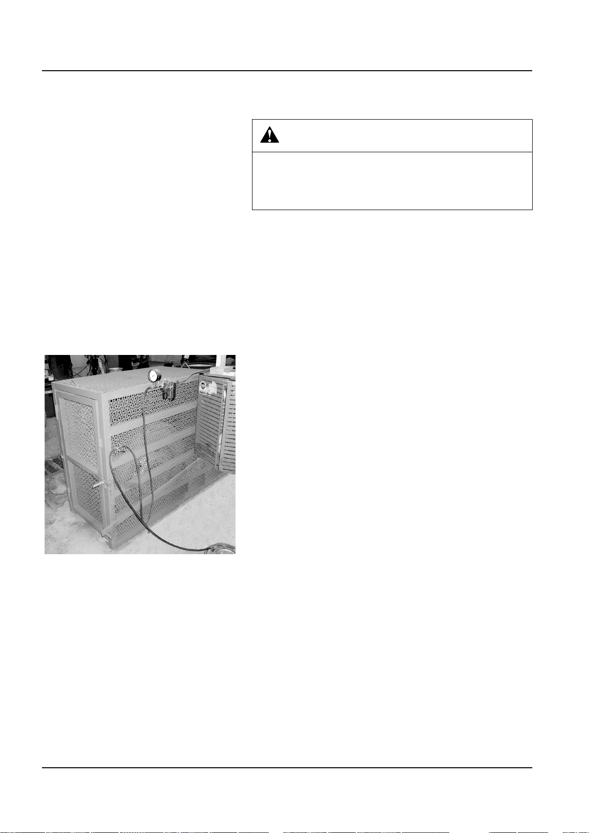
Tyres
DANGER
Tyres should be regarded as pressurized containers. They consti‐
tute a risk of injury if handled incorrectly.
Never repair damaged tyres, rims, or rim lock rings. Tyre repairs
should only be performed by authorized service personnel.
Risks
Dismantling wheels: tyres, rims, or lock rings can be thrown.
Tyre pressures: tyres, rims, or lock rings can be thrown.
Precautions
Deflate the tyre before starting to work with the wheel.
•
Check that tyres, rims, and lock rings are intact. Never repair
•
damaged tyres, rims, or lock rings.
Use a protective screen, hearing protection and safety glasses.
•
Fig. : Protective screen
TL2 Maintenance Manual
591 003 Default

1
Table of content
C Preventive maintenance 3
For the service personnel 3
Maintenance programme 5
Initial maintenance 5
Scheduled maintenance 6
TL2 Maintenance Manual
591 003 Default

2
TL2 Maintenance Manual
591 003 Default
 Loading...