


00
General
Technical
Handbook
ContChamp
DRD
S
This Handbook deals with the design
and maintenance of Kalmar machines,
type DRD-S for the handling of containers.
In addition, it gives details of troubleshooting and the most common
corrective maintenance.
10
20
30
40
50
Chassis and cab
Electrical system
Engine
Transmission,
drive axle, brakes
Operation and other matters that are
primarily of interest to the operator are
included it the Instruction Manual.
Kalmar Industries AB
This handbook applies to
machines from and including
machine number T34107.0784 as
well as T34107.0621 and
T34107.0769, see next page.
We reserve the right to modify
our design and material specifications without prior notice.
Publ. Nr 920 937 9407 04-10
AdEra Dokument AB, Växjö 2004
60
70
80
90
Steering axle
Hydraulic system
Boom and attachment
Periodic supervision

This Handbook applies to machines from and including machine number
T34107.0784 as well as T34107.0621 and T34107.0769
These machines are of a new design that entails the f ollowing dif ferences from ol der machines. The changes do not apply to machines with combi-attachments or top-lift with pileslope.
1. The electrical system is equipped with a separat e KDU for the top-lift, comp onent number 791. The KDU
communicates with ECU 2 via a CAN bus.
2. The main valve of the top-lift is fed by a variable hydraulic pump.
The main valve is common for all of the top-lift’s functions.
3. The length adjustment of the top-lift is manoeu vred by means of a hydraulic motor and chain.
4. The top-lift rotation brake is manoeuvred completely hydraulically.

ContChamp DRD-S
Technical Handbook
9407
Contents
04-10
S.Grupp 00
1
Contents
Group 00
Safety regulations...................................... .... ........................... 2
General...................................................................................... 6
Design – Overview .............................................................. 6
Component units ........................................... ... ... ............... 7
Supplementary books ......................................................... 9
Replacement system – Spare parts ................................... 9
Tools .............................. .......................... ......................... .. 9
Tightening torques.............................................................. 10
System of units ................................................................. 12

ContChamp DRD-S
Technical Handbook
Safety regulations
9407
04-10
S.Grupp 00
2
It is important that you read the instruction
manual.
Incorrect handling can lead to personal injury or damage to products and/or property . Therefore , read the instruction book very carefully before ope rating the truck.
The instruction manual contains important information
about your Kalmar truck, about the operation of the
truck, about safety during oper ation and about the
truck's daily maintenance. In addition, you will find useful information that will make operations easier for y ou
in your daily work.
The instruction manual must always be kept in the machine. If the manual should be lost, a replacement m ust
be immediately obtained. Never use a machine with a
missing instruction manual.
Ask your foreman/group leader if there is anything in
the manual that you do not understand or if you f eel that
information is missing in any area.
The symbol is used on our products in certain
cases and then refers to important information contained in the instruction manual. Make sure that warn ing and information symbols are always clearly visible
and legible. Replace symbols tha t have been d amaged
or painted over.
In this instruction manual war n in gs ar e inserted that
apply to your own safety. Warnings point out the risk of
accident that can cause personal injury.
WARNING!
Warns of the risk of seriou s personal injury, possible death and/or serious dama ge to product or
property if the regulations are not followed.
For technical warnings, that point out the risk of break
down, the word IMPORTANT is used:
Safety regulations aimed at reducing the
risk of personal injury and damage to
loads or other property.
Intended of use
z The truck may only be used for the purpose for
which it was intended, namely, to lift and transport
goods, the weight of which doe s not exceed the
maximum permitted load capacity of the truck.
z The truck may not, without specific permission
from Kalmar, be mod ified or re-built so that its function or performance is altered.
z The truck may not be driven on public highways if
it has not been adapted to comply with national
road safety regulations.
Operator requirements
z The truck may only be driven by operators who
have been specially trained and who have the
company's authority to do so.
z Laws and other regulations relati ng to driving li-
cence, operator ID, log book, etc., must be followed at all times.
z The operator must be aw are of and f oll ow all local
safety regulations.
z It is always the responsibility of the operator to en-
sure that the truck has appro v ed fire e xt inguishing
equipment in accordance with currently applicab le
regulations.
Operation of the truck is prohibited:
z If any of the fitted safety equipment, such as rear
view mirrors, headlights, reversing alarm (optional), does not function correctly.
z If there is a fault with the brakes, steering or lift
equipment.
z If it has been repaired, modified or adjusted with-
out the approval of the work supervisor.
z If the truck is fitted with tyres not appro ved by
Kalmar.
IMPORTANT!
Is used to draw attention to such occurrences
that can cause damage to the product or
property.
For information that facilitates the working process or
handling, N.B. is used:
N.B. Draws attention to useful information tha t
helps the working process.
Emergency exit
If the doors should not o pen in an emergency, open the
rear window for emergency exit.
A rear window that can be opened is standard on machines with hydraulically moveable cab. Optional on
other machines.
Continued on next page
KL749

ContChamp DRD-S
Technical Handbook
Safety regulations
9407
04-10
S.Grupp 00
3
Continued from previous page
Operating regulations
z Before starting, make sure that the cab is locked
in the rear-most position by me ans of the latches,
one on each side. The latches must be secured
with spring pins. (Applies to manually moveable
cabs).
z Before starting, always check to ensure that no-
body is in the way of the truck or its equipment.
z The operator must alw ays f ace the direction of op -
eration and take particular care in areas wher e
persons or other vehicles are likely to appear in
the vicinity . If visibility is limited by the load, the operator should operate the truck in reverse.
z It is prohibited to walk or stand underneath raised
forks or other equipment, whether the y are loaded
or not.
z It is prohibited to transport passengers on the
truck outside the cab or on the load. Passengers
may be transported inside the cab only on condition that it is equipped with a fixed passenger
seat.
z It is prohibited to lift people if the truck is not
equipped with an approved lift cage.
z It is prohibited to exceed the load capacity of the
truck. See capacity plate and loading diagram.
z It is prohibited to transport loads in the raised po-
sition as this entails a risk of the truck tipping. All
transportation shall take place with the load in the
transport position.
z The operator must adapt the speed of the truck to
the character of the load, conditions of visibility,
the character of the roadway/surface, etc.
z The operator shall avoid powerful acceleration
and braking when turning. In addition, the operator shall always moderate the speed of the truck
when turning so as to avoid the risk of lateral skidding or tipping.
z The operator shall take pa rticular care when oper-
ating in the vicinity of electrical power lines, viaducts, quay-sides, ramps, gates/doors etc.
z Safety belts must always be worn, if fitted. In the
event of the truck tipping, always remain in the cab
and grip the steering wheel securely. Never try to
jump out of the cab.
z The parking brake can also be used as an EMER-
GENCY BRAKE. However, having been used f or
emergency braking, the brake linings must be
checked and repl aced if necessary. If the parking
brake has been mechanically released, it must
always be rese t in order for the truck to regain the
parking brake function.
Interrupted operation, parking
z Always check that the gear lever is in the neutral
position before turning the ignition k ey to restart or
to reset an emergency stop.
z Never leave the operator's cab without applying
the parking brake (ON position).
z Always remov e the ignition key if the truck is to be
left unattended.
Other important points to remember
z The truck's hydraulic system includes high pres-
sure hydraulic accumulators . Always be extremely
careful when working with the hydraulic system
and avoid being unnecessarily close to the hydraulic equipment, lines and hoses. Before working on the hydraulic system, t he accumulators
must be emptied into the tank, with the help o f the
special accumulator evacuation valve.
z Handle batteries and junction boxes with great
care. The batteries must alwa ys be protected over
the poles and connections.
z Always rectify any damage or wear and tear that
can risk personal safety or that can af fect the functions of the truck or its service life.
z Avoid touching oils and greases. Avoid inhaling
exhaust and oil fumes.
z Always use step s and handrails when en tering or
leaving the machine - Never jump!
T o avoid t he risk of slipping, tread only on anti-slip
surfaces. If the anti-slip protection has become
worn, loose or in any way less effective, it should
be replaced.
z Welding painted steel produces poisonous gas-
ses. Paint should therefore be stripped before
welding, good ventilation ensured and/or face
mask with filter used.
z Mobile phones used in the cab must alw a ys ha v e
fixed connections to the machine’s elec trical system, with a fixed antenna outside the machine,
mounted in accordance with the manufacturer’s
instructions. This will avoid interference with the
machine’s important electronic functions.
Operating with attachments
z The operator must always take the effect of the
wind into account when handling containers.
Avoid lifting with a wind strength in excess of 12
m/s (27 mph/40 feet per second).
z Always drive carefully so as to avoid attachments
colliding with pillars, cables, etc.
z Carefully study the "Lift methods" section of the
instruction manual.
z The tensile strength of the top pane can be seri-
ously weakened by exposure to elements that
contain: Aromatic hy droca rbo n, ketone, esters or
chlorinated hydrocarbon.
Regularly check the surface condition of the top
pane and clean only with screen wash or other
mild cleaning fluid. After cleaning, rinse tho roughly with warm water. It is prohibited to modify or in
any other way make altera tions to the top pane.
Immediately replace damaged top panes t hat
show signs of cracking or scratching.
CE marking
All trucks and equipment (though not thoses fitted on
the truck or intended as spare parts) supplied from Kalmar are CE marked, which indicates that th ey co mply
with the requirements of the EU Machine Saf ety Directive. In addition, each truck has a so called, “EU Declaration of Conformity” which is the legal pr oof that the
truck complies with the “health and safety” requirements laid down in the Machine Safety Directive, the
EMC directive (electro-magnetic compatibility) and the
LVD directive (electrical equipment).
Vibration standard
The truck complies with and is below the limits for vibration standard EN 13059.

ContChamp DRD-S
Technical Handbook
Safety regulations
Safety regulations
9407
04-10
S.Grupp 00
4
z Only authorized and qualified personnel may
work with the safety system. (ECS-system)
z If the overload safety system override functio n
has been used, there is a risk of forw ard tipping.
The truck should be operated with e xtreme car e
to prevent accidents.
z Great care must be exercised at all times when
driving the machine. Always re member the great
height and width of the machine so that collision
with beams, cables etc. is avoided
z It is prohibited to start lifting a container if the
warning light TWIST -LOCK UNLOCKED (red) is
lit or if any of the warning lights TWIST-LOCK
LOCKED (green) or ALIGNMENT (orange) are
extinguished. N.B. the ALIGNMENT warning
light goes out once the lift has begun.
z If the safety system warning lamps are not func-
tioning, the system must be immediately repaired. To use a truck with faulty w arning lamps
is a great safety risk.
z Do not drive the truck with load raised high
above the gr ound, since the truck ma y ov erturn.
The transport of heavy loads must be carried out
with the load as close to the truck as possible,
i.e. with the boom retracted and lowered as far
as possible without obstructing vision, see picture below.
z Never run hands or fingers along any tu bes,
pipes or hoses whilst investigating for possible
leaks as some of these lines (diesel fuel, hydraulic, steering, etc.) operate at extremely high
pressures and even the most minute of leaks
can cause oil or fluid to penetrate the skin.
z Under no circumstances may compressed air be
used to remove a hydraulic piston from its cylinder.
z Always attend to damage and w ear that ma y be
of significance to the perf ormance and useful life
of the truck or to the safety of the personnel.
z Follow the safety rules whenever carrying out
service work on the air conditioner. The refrigerant is injurious to the skin and eyes. Only authorized service personnel may repair the system.
z The truck’s h ydraulic syst em includes high pres-
sure hydraulic accumulators. Bef ore working on
the hydraulic system, the accumulators must be
emptied into the tank, with the help of the special
accumulator evacuation valve. Also valve B for
emergency pressure to servo system must be
opened.
z Never carry out any service work on the boom or
attachment when the engine is running.
Transport position
KL591
KL1103
A. Quick evacuation valve, accumulators
B. Valve for emergency pressure to servo system

ContChamp DRD-S
Technical Handbook
Safety regulations
Safety instructions for working with tyres
9407
04-10
S.Grupp 00
5
z Tyre changing can be dangerous and should only be
carried out by specially trained
personnel using proper tools and procedures. Failure to comply with these procedures may result in
faulty positioning of the tyre and/or rim and cause the
assembly to burst with explosive force sufficient to
cause physical injury or death. Never fit or use damaged tyres or rims.
z Ne v er attempt to weld on an inflated tyr e/rim assem-
bly.
z Never let anyone assemble or disassemble tyres
without proper training.
z Never run the truck on one tyre of a dual assembly.
The load capacity of a single tyre is then dangerously exceeded and oper ation in this manner may damage the rim.
z Deflation and dismantling
– Always block the tyre and wheel on the opposite
side of the vehicle bef ore yo u place the jac k in position. Always crib up the blocks to prevent the
jack from slipping.
– Always check the tyre/rim assembly for proper
component seating prior to removal from the
truck.
– Always deflate the t yre by removing the v alve core
prior to removing the complete assembly from the
truck or dismantling any of th e component. Before
loosening mounting bolts, run a wire through the
valve stem to en sure that it is not blocked. Ice or
dirt can prevent all the air from escaping. Deflate
and remove valve cores from both tyres of a dua l
assembly.
– Never position body in front of the rim during de-
flation.
– Always follow assembly and dismantling proce-
dures outlined in the manufacturer’s instruction
manual, or other reconized indu stry instruction
manuals. Use proper rubber lubricant.
– Never use a steel hammer to assembling or dis-
mantling rim components – use a lead, brass or
plastic type mallets. The correct tools are available through rim/wheel distributors.
– remove bead seat band slowly to prevent acci-
dents. support the band with your thigh and ro ll it
slowly to the ground in order to protect back and
toes.
– Disassembly tools apply pressure to rim flanges
to unseat tyre beads. Keep your fingers clear.
Slant disassembly tool about 10 degrees to keep
it firmly in place. Always stand to one side when
applying hydraulic pressure. Should the tool slip
off, it may cause fatal injury.
z Rim inspection
– Check rim components periodically for fatigue
cracks. Replace all cracked, badly worn, damaged and sev erely rusted components.
– Always select the correct tyre size and construc-
tion matching the manuf actur er’s rim or wheel rating and size.
– Do not use over-size tyres, too large for the rims,
e.g. 14.5 inch tyres with 14 inch rims or 16.5 inch
tyres with 16 inch rims.
– Never use damaged, worn or corroded rims/
wheels or fitting hardware. Always verify that the
rim is in a serviceable conditioning.
– Always clean and repaint lightly rusted rims.
– Never use a rim/wheel component that ca n not be
identified. Check rim parts against multi-
piece rim/wheel matching charts.
z Assembly and inflation
– It is important that the inflation equipment is
equipped with a water separator to remove mois-
ture from the air line in order to pr ev ent co rrosion.
Check the separator periodically to ensure that it
is working properly.
– Make sure that the lockring is in its right position.
– Never mi x different manuf acturer’ s parts since this
is potentially dangerous. Always check manufac-
turer for approval.
– Never seat rings with hammering while the tyre is
inflated. Do not hammer on an inflated or partially
inflated tyre/rim assembly.
– Always double check to ensure that the rim as-
semblies have been correctly assembled and that
securing studs and nuts are tightened to the cor-
rect torque setting.
– Never inflate tyres before all side and lockrings
are in place. Check components for proper as-
sembly after pumping to appro xim ately 5 psi (=34
kPa, =0.34 bar)
– When adding air to a tyre on an industrial truck,
use a clip-on chuck and stay out of the dange r ar-
ea. If the tyres has been run flat then the rim must
be dismantled and all parts inspected f or damage .
– Under-inflated tyres have a serious effect on the
stability of the truck and reduces the safe load
handling capacity. Always maintain tyres at the
correct inflation pressures. Check inflation pres-
sure daily. Do not over-inflate.
– Inspect tyres regulary – every day if possible.
Look for and remove brok en gla ss, torn pieces of
tread, embedded metal chips etc. Inspect f or une-
ven or rapid tread wear, usually caused by me-
chanical irregularities, such as brakes out of
adjustment or excessive toe-in and toe-out. If dis-
covered, correc t the irregularity immediately.
z When installing and tight ening trail wheel bolts, ob-
serve the following:
– Ensure that trail wheel or hub mounting surfaces
and trail wheel fastener mounting surfaces are
clean and free from paint and grease.
– Tighten bolts to specified torque settings . use
staggered sequence; i.e. top bolt , bott om bolt e tc.

ContChamp DRD-S
Technical Handbook
General
9407
04-10
S.Grupp 00
6
Design – Overview
Kalmar DRD420–450 model S diesel trucks are of sturdy design
for particularly heavy duty handling of 20-40' loaded con tainers.
They are built around a chassis which has high strength and torsional stiffness and an extremely low centre of gravity.
The operator’ s cab is prov ided with vibr ation isolat ion and so und
insulation and offers excellent all-round visibility.
There are many adjustments that can be made to the operator's
driving position. The position of the seat, back support and firmness of the driving seat can be adjusted in a number of ways.
The trucks are equipped with a sliding cab . This puts the opera tor
in an exceptional position to superwise th e top lift attachment and
offers excellent accessibility to the transmission and hydraulic
pumps. The engine is easily accessib le through a remo vab le running board.
To special order, the trucks are equipped with hydraulically powered sliding cab.
DRD420-60S5
KL586C
DRD420-65S5 with 20-40’ adjustable top lift

ContChamp DRD-S
Technical Handbook
General
9407
04-10
S.Grupp 00
7
The Volvo six-cylinder turbocharged engine, combined with a
four-speed gearbox with torque converter, prov ides smooth
power whenever needed.
The drive axle with hub reduction, oil-cooled h y draulic br ak e system and pendulum-mounted steered axle with double-acting
steering cylinder satisfy very strict demands on strength and mobility when travelling on irregular surfaces.
The hydraulic system is reliable and has high performance.
Component units
z Sound-insulated operator’ s cab with excellent all-round visibil-
ity. The non-slip, substantial steps provide convenient access
to the cab. As an optional extra, a hydraulically movable cab
is available.
z ECS-system which controls the electric servo circuits and also
overload protection system. (With elect ronic balance, module
60 or 52, the loading conditions are indicated on a displa y on
the ECS-terminal in the operator’s cab.)
z Engine - Volvo TWD1031VE/TWD1231VE six-cylinder, four-
stroke, turbocharged di esel engine with direct injection and
thermostatically controlled water cooling.
The engine is equipped with:
– Injection pump with centrifugal gov ernor that compensates
for load variations.
– Smoke limiter f or reduced free acceleration and full load
smoke.
–Alternator.
z Gearbox with torque converter
– Constant-mesh gearbox changes b y means of hydraulically
activated clutches which are electrically operated.
– Torque converter, which is a hydraulic coupling that ampli-
fies the output torque on an increase in load. Torque conversion takes place smoothly and steplessly throughout th e
engine speed range.
– Oil cooler connected to the engine cooling system for cool-
ing the oil in the gearbox and torque converter.
– Oil pump which supplies oil under pressure to the gearbo x
and torque converter.
– Full-flow oil filter for effective cleaning of the gearbox oil.
z Drive axle with two-stage reduction - in the diffe rential and the
hub reductions.
– Hydraulic, oil cooled disk brak es – wet disk brak es – for the
foot brake.
– Disc type parking brake applied by sturdy springs and re-
leased by hydraulic oil pressure.

ContChamp DRD-S
Technical Handbook
General
z Hydraulic system, that occurs in two versions:
9407
04-10
S.Grupp 00
8
1. With common tank for all hydraulic and brake circuits.
– a double variab le hydr aulic pump , feeds L ift 1, Extension 1,
hydraulic servo, steering system
– a double variab le hydr aulic pump , feeds L ift 2, Extension 2,
attachment functions
– a fixed, wing type pum p f or the feeding of the brake system
– hydraulic fluid cooler for the brake system cooling circuit
2. With a separate tank f or th e working hydraulics and a separ ate tank for the brake circuit.
– a double variab le hydr aulic pump , feeds L ift 1, Extension 1,
hydraulic servo, steering system
– a double variab le hydr aulic pump , feeds L ift 2, Extension 2,
attachment functions
– a fixed, wing type pum p f or the feeding of the brake system
– a hydraulic fluid cooler for the brake system cooling circuit
– a fixed, wing type pump for the circulation of the main tank’ s
hydraulic fluid through a hydraulic fluid cooler
– hydraulic fluid cooler for the main tank
z Main valves for controlling the main hydraulics . The valves are
controlled by an electro-hydraulic servo system from the cab.
An electro-hydraulic servo system is available as an option.
z High pressure filters for effe ctive cleaning of the h ydraulic fluid
before it is returned to the tank.
z Priority valve giving priority to the steering system when re-
quired.
z Steering valve (Orbitrol) - flow-control valve which supplies h y-
draulic fluid to the steering cylinder.
z A hydraulic oil cooler with electrically powered fan
z Steered axle with pendulum mounting and double-acting
steering cylinder.
z Lift cylinders equipped with blocking valves, which eliminate
any undesirable sinking of the load. A regeneration system
gives high lifting speed at no load conditions.
z Boom of a slender, high -tensile ste el construction. Th e boom
is pivot-mounted and comprises a fixed and a telescope section manoeuvred by means of a double-acting extension cylinder. The extension system is equipped with regeneration
system for quick boom-out speed at no-load conditions.
z Top-lift attachment, adjustable for handling 20 and 40 foot
containers.

ContChamp DRD-S
Technical Handbook
General
9407
04-10
S.Grupp 00
9
Supplementary books
In addition to the Instruction Manual and the Technical Handbook, the following books are delivered with every truck.
Spare parts catalogue
Instruction Manual for Volvo Industrial engines
Replacement system - Spare parts
Kalmar operates a system of replacement parts, repair kits and
gasket sets covering most of the vital components of the truck.
For the contents of these kits, see the Spare parts catalogue.
Tools
Kalmar offers a wide range of tools for truck maintenance work.
For further information, please contact Kalmar's service depart-
ment.

ContChamp DRD-S
Technical Handbook
General
9407
04-10
S.Grupp 00
10
Tightening torques
(According to Kalmar K Standards 20060.0001)
The tightening torques are applicab le to steel bolts and n uts tight-
ened with a torque wrench under the following conditions:
Surface treatment
Condition Lubriation
Bolt Nut
1 untreated untreated oiled
bright galvanised
2
3 hot-dip galvanised bright galvanised dry or oiled
The values specified in Table 1 are applicable to nut-and-bolt
joints, but can also be used f or bolts fitted into tapped holes . However , in the latter case, the preloading f orce will be somewhat lower, depending on its depth of engagement.
When tightening by machine, the torque specified in Table 1
should be reduced by approx. 5%, due to the increased scatter
and to prevent the bolt from being tightened beyond its yield
point.
Quality 8,8 10,9 12,9
Thread
M fin
M8×1
M10×1,25
M12×1,25
M16×1,5
M18×1,5
bright galvanised
bright galvanised
Tightening torque, Nm
12311
27
54
96
230
330
24
48
85
205
294
untreated
bright galvanised
bright galvanised
Condition
30
61
108
260
373
135
323
466
dry or oiled
39
76
46
91
162
388
559
M20×1,5
M24×2
M30×2
M36×3
460
786
2660
1560
409
700
1388
2367
520
888
1763
3005
647
1100
2200
3730
777
1330
2640
4480
ContChamp DRD-S
Technical Handbook
General
To reduce the risk of settlement of the material and the
associated reduction in the preloading f orce if the hardness of t he
surface supporting the bolt head or nut is lower than 200 HB, a
washer should be fitted under the bolt head and nut. This is not
applicable if flanged bolts or flanged nuts are used.
When tightening is carried out, the specified torque shou ld be applied without pause, to ensure that the torque wrench will not be
tripped by the static friction before the joint has been tightened to
the specified torque.
Quality 8,8 10,9 12,9
Tightening torque, Nm
Condition
Thread
M
12311
9407
04-10
S.Grupp 00
11
4
5
6
8
10
12
16
20
24
30
Quality 8,8 10,9 12,9
Thread
UNC
1/4
5/16
3/8
7/16
1/2
3,2
6,4
11
26
52
91
220
430
750
1480
12311
12,5
25
44
70
107
2,9
5,7
9,8
24
47
81
198
386
668
1317
Tightening torque, Nm
11,1
22,3
39
62
95
3,6
7,2
12,5
30
59
103
250
49
848
1672
Condition
14,1
28,3
50
79
121
4,6
9,1
16
38
74
128
313
620
1050
2080
17,6
35
62
100
151
5,5
11
19
45
89
154
375
732
1270
2500
20
42
73
118
178
9/16
5/8
3/4
7/8
1
1 1/8
1 1/4
1 3/8
1 1/2
153
210
370
594
889
1260
1760
2320
3060
136
187
390
528
791
1120
1565
2065
2720
173
237
418
671
1005
1424
1990
2620
3455
216
298
524
839
1260
1780
2490
3280
4320
255
353
619
990
1480
2100
2940
3870
5100

ContChamp DRD-S
Technical Handbook
General
Quality 8,8 10,9 12,9
Tightening torque, Nm
Condition
Thread
UNF
12311
9407
04-10
S.Grupp 00
12
1/4
5/16
3/8
7/16
1/2
9/16
5/8
3/4
7/8
1
1 1/8
1 1/4
1 3/8
1 1/2
13
26
47
75
114
164
227
396
629
937
1350
1860
2500
3260
11
23
42
66
101
145
202
352
560
834
1200
1655
2225
2900
14
29
53
85
128
185
256
447
710
1058
1525
2100
2825
3680
19
37
67
107
162
231
321
559
889
1320
1900
2630
3530
4610
System of units
The SI system of units is employed in this handbook:
The conversion factors are as follows:
Pressure
megapascal bar Kilogram-force per
square centimetre,
kpf/cm²
Atmosphere, at
Pound-force
per square
inch,
psi
22
44
79
126
191
273
379
661
1050
1560
2250
3110
4170
5450
1
0,1
0,098
Torque
Newtonmeter
Nm
1
9,81
Power
Kilowatt
kW
1
0,735
10
1
0,98
10,2
1,02
1
Kilogram force-metre
kgf m
0,102
1
Horsepower (metric)hpHorsepower
1,36
1
145
14.5
14.2
Pound-force foot
lbf ft
0.74
7.23
hp
1.34
0.986

ContChamp DRD-S
Technical Handbook
9407
Contents
04-10
S.Grupp 10
1
Group 10
Chassis and cab
Specification .............................................................................. 2
Chassis...................................................................................... 3
Description ........................................................................... 3
Chassis............................................................................ 3
Support jacks................................................................... 3
Operator’s cab................................................................. 4
Steering column .............................................................. 9
Hydraulics control unit................................................... 10
Service ............................................................................... 11
Changing the fresh air filter ........................................... 11
Check and lubrication of brake pedal............................ 11
Windscreen wipers........................................................ 12
Air conditioning unit ................................................................. 13
Description ......................................................................... 13
Service ............................................................................... 16
Checking the air conditioning unit ................................. 16

ContChamp DRD-S
Technical Handbook
Specifications
Air conditioner
z Cab unit
Circulated air flow 500-600 m
Electric power consumption approx. 350 W
z Compressor
Max. speed 4000 r/min
Refrigerant R134a *)
Electric power consumption approx. 50 W
Oil capacity Zexel PAG SP-20 1.5 dl
z Condenser
Electric power consumption 250 W
z Cooling effect 6-8,5 kW
z Heating effect approx. 11 kW
*) Refrigerant R12 is no longer in production due to legislation
3
/h
9407
04-10
S.Grupp 10
2

ContChamp DRD-S
Technical Handbook
Chassis
Description
9407
04-10
S.Grupp 10
3
Chassis
The chassis consists of:
z A unit construction frame built up around t wo box- sections for
best possible strength.
z Mountings for the drive axle, steered axle, telescope-boom,
lifting cylinders and transmission.
z The necessary counterweights to provide a very low centre of
gravity. Moreover , the ste ered axle is designed to serve as an
additional counterweight.
The hydraulic oil tank and t he fuel tank are produced as separat e
units and are bolted to the side of the chassis. The tanks have a
low profile, which contributes to the good visibility.
Support jacks
Certain machines are equipped with support jacks to increase
the capacity in the third container row, see group 20.
KL1436

ContChamp DRD-S
Technical Handbook
Operator’s cab
Description
9407
04-10
S.Grupp 10
Operator’s cab
The operator’ s cab is a separ ate structure and rests on the chassis on rubber dampers. The operator’s seat, steering wheel and
hydraulic control le vers can be adjusted for best possible operator
comfort. Effective insulation minimises the vibrations and sound
level in the cab.
The standard heating system consists of a fan and heater for
heating the air in the cab by recirculation. Fresh air is drawn in
through a ventilation air filter. Full air conditioning, with cooling,
heating and dehumidification, is available to special order.
4
1
4
2
3
1. Steering column with control levers and switches, ECS-terminal
2. Heating system
3. Air filter
4. Electrical central unit

ContChamp DRD-S
Technical Handbook
31 4 5 2 6
Operator’s cab
Description
9407
04-10
S.Grupp 10
5
1
23
4
F
N
R
R
45
3
L
0
789 10111213
1. Gear selector
FORWARD/NEUTRAL/REVERSE 1/2/3/4
2. Lever DIRECTION INDICATORS/HORN
FRONT WINDSCREEN WASHER/
FRONT WIPERS/MAIN BEAM
3. Instrument panel
4. Steering wheel panel
5. Starting switch
KL1406
6. Control lever and control panel for hydraulic functions
7. Electrical central unit with fuses and relays
8. Brake pedals, normal driving brake
9. Release clutch
10.Accelerator pedal
11.Steering wheel adjustment
12.Servo circuit breaker
13.Parking brake

ContChamp DRD-S
Technical Handbook
Operator’s cab
Description
9407
04-10
S.Grupp 10
6
66
21
24
25
26
27
28
22
29
1
23
4
30
31
54
23
33
32
55 56 60 59
F
N
R
34
KL581
39
38
37
36
35
40 41 42 43 44 45 52 53
46
47 48 49 50 51
R
1
2
3
4
5
KL580
KL582
L
0
57 58 64 61 62 63
21. Pressure gauge, gearbox oil pressure
22. Fuel gauge
23. Temperature gauge, engine coolant temperature
24. Switch, working lights
25. Switch, working lights
26. Switch, working lights
27. Switch, flashing beacon
28. Switch, hazard warning lights
29. Switch, driving lights
30. Spare
31. Spare
32. Spare
33. Spare
34. Switch, compressor air conditioning
1)
35. Control, recirculation/fresh air
36. Control, defrost/cab
37. Switch, fan
38. Control, heat
39. Control, cold
KL675
1)
40. Spare
41. Spare
42. Warning lamp, battery charging
43. Warning lamp, low engine oil pressure
44. Warning lamp, low gearbox oil pressure
45. Warning lamp, low brake pressure
(accumulator pressure)
46. Warning lamp, low engine coolant level
47. Indicating lamp, preheating
48. Warning lamp, high engine coolant temperature
49. Warning lamp, high gearbox oil temperature
50. Spare
51. Warning lamp, parking brake ON
52. Spare
53. Spare
54. Spare (Green lamp TWIST-LOCKS LOCKED)
55. Spare (Orange lamp ALIGNMENT)
56. Spare (Red lamp TWIST-LOCKS UNLOCKED)
57. Spare (LOCK/UNLOCK TWIST-LOCKS)
58. Spare (LENGTH ADJUSTMENT 20-40')
59. Indicating lamp, headlights
60. Indicating lamp, direction indicators
61. ECS terminal
62. Switch, windscreen wiper, rear
63. Switch, windscreen wiper, roof
64. Spare
65. Fuses
66. Hour meter
1)
Optional
65

ContChamp DRD-S
Technical Handbook
Operator’s cab
Description
9407
04-10
S.Grupp 10
7
1
2a
3
4
2b
56
7
8
9
10
Joy-stick functions
1)
1. Tilt
2. a. Locking of til t
b. Locking of levelling
3. Rotation
4. Side shift
5. Vertical lift
6. Boom OUT/IN
7. Levelling
8. Length adjustment 20'–40'
9. Unlocking of twist-locks
10.LIFT/LOWER
1)
Optional
1)
1)
1)
1)
Switch functions
13. Rotation limiting
15. AUT = Automatic locking of
twist-locks. The parking brake must
be OFF
MAN = Manual locking of
twist-locks (spring-back)
Unlocking off twist-locks,
see Joy-stick function 9 above
17. Stop at 30' and 35'
18. Cab movemen t ho rizontal/vertical
19. Support jacks DOWN/UP 1)
20a. Red lamp, the support jacks have
left the upper position
20b. Green lamp, support jacks down
1)
Optional
1)
1)
1)
1)
Button 17 for the connection and disconnection of
the 30' and 35' stops
The position gives crawling speed the whole time during extension and retraction. In order to by-pass the 30' stop press
and thereafter . The next stop will be 35'.
It is practical to connect in once the 30' position has been
passed.
N.B. When operating a machine
which is equipped with hydraulically moveable cab, the doors should
be closed or the ca b in it s rea r posi tion otherwise all functions will be
broken.

ContChamp DRD-S
Technical Handbook
Operator’s cab
Description
9407
04-10
S.Grupp 10
8
Lamp panel on the boom
Container handling
A. Twist-locks locked, green
B. Alignment, orange
C. Twist-locks unlocked, red
Lit lamps at container lift:
A+B
Go out after lift: B
A
C
KL20
B
WARNING!
Overriding of the safety
system is at one's own risk
and involves a risk of forward tipping.
Engagement and
disengagement
of servo circuits
Override
(Only in emergency situations)
1. Lower
2. Container coupling
KL 1407
ContChamp DRD-S
Technical Handbook
Operator’s cab
Description
9407
04-10
S.Grupp 10
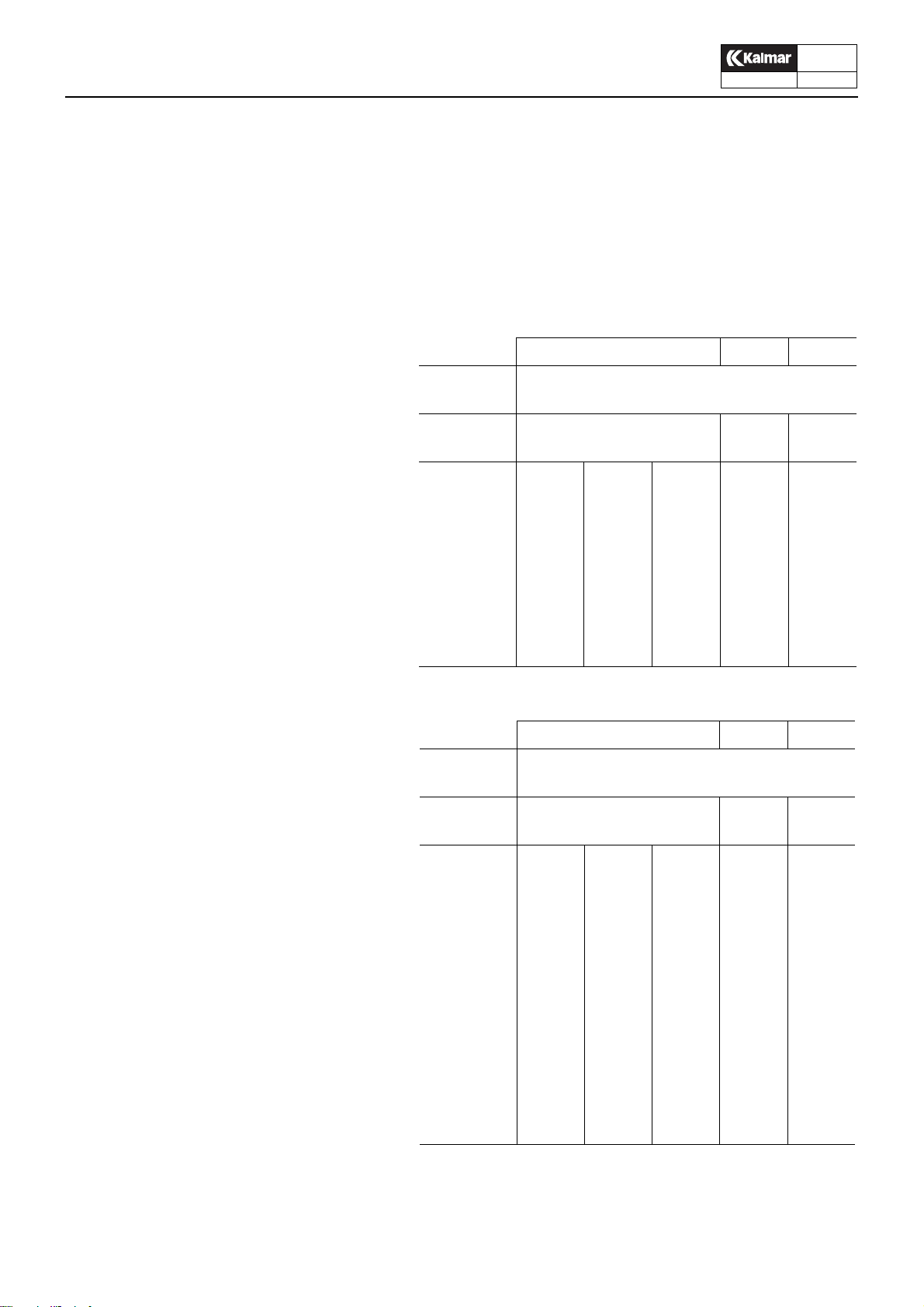
Steering column
Surrounding the steering column are multi-function levers for
gear changing, indicators, windshie ld wipers , et c., as w ell as the
instrument panel with the ECS terminal. At the very foot of the
steering column is the steering valve (Orbitrol), activated by the
steering wheel via an angled gear. The steering column is
equipped with an adjustment knob for the alteration of steering
wheel height and rake.
.
9
1
23
4
1
F
N
R
R
1
2
3
4
5
L
0
2
3
KL580A
4
1. Gear lever
2. Multi-function lever
3. ECS terminal
4. Steering wheel adjustment
knob
5. Angled gear
6. Orbitrol steering valve
KL588
6
5
Column steering

ContChamp DRD-S
Technical Handbook
KL 1407
Operator’s cab
Description
9407
04-10
S.Grupp 10
Hydraulics control unit
Control lever and switches used to manoeuvre the hydraulics
system are located on an adjustable console with comfortable
working position
The control lever is a jo ystick that is electroh ydr aulically connected to the main valves.
10
1
1. Control lever
2. Connection and disconnection of servo circuits
3. Control switches for attachment
4. Switch for overriding of safety system (for
use in emergency situations only). Affects
both overload protection and container connection.
23
4
WARNING!
Overriding of the safety sy stem is carried out at y our own
risk as such overriding i nvolves a ri sk of f or war d tippin g.
ContChamp DRD-S
Technical Handbook
Operator’s cab
Service
04-10
S.Grupp 10
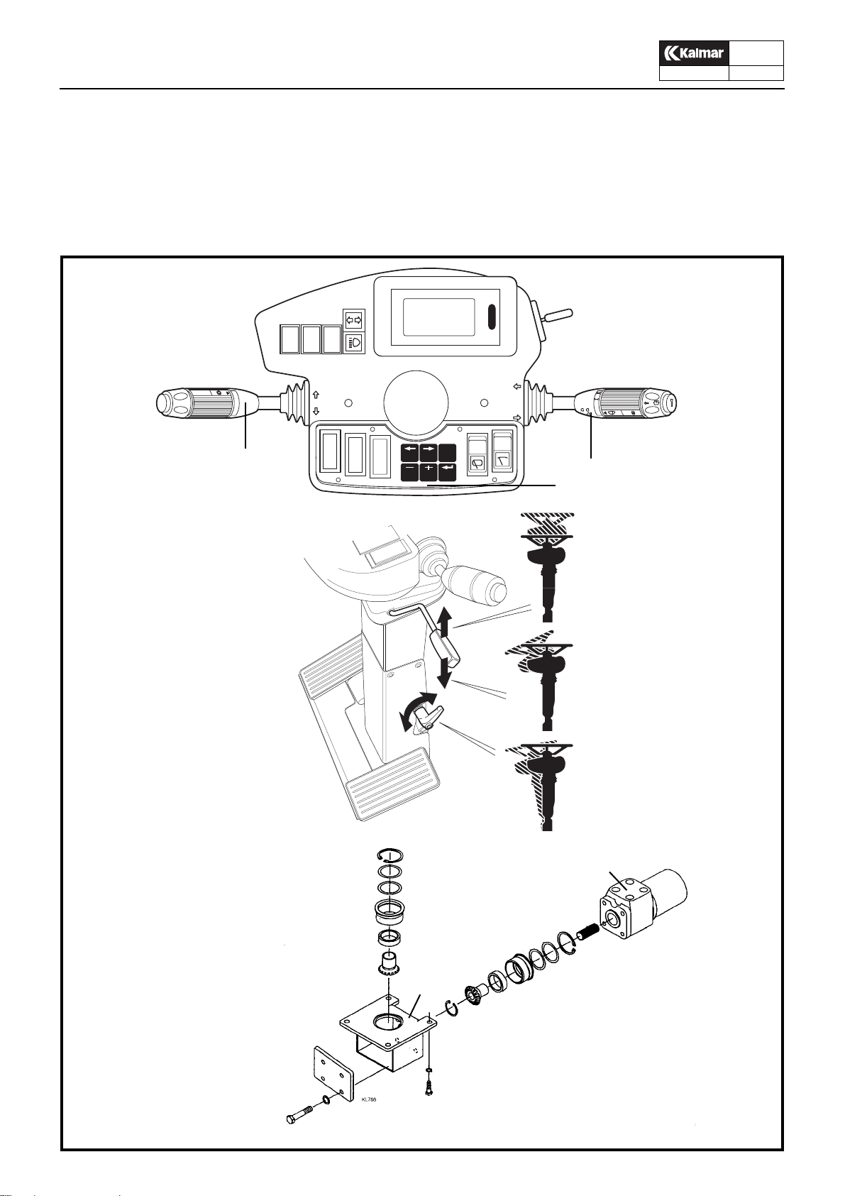
Changing the fresh air filter
(every 200 hours or when needed)
1. Remove the filter casing retaining bolts and remove the filter
element.
2. Wash the filter insert with water and detergent or by using a
high pressure washer. Replace the insert if necessary.
3. Reinstall the filter insert.
9407
11
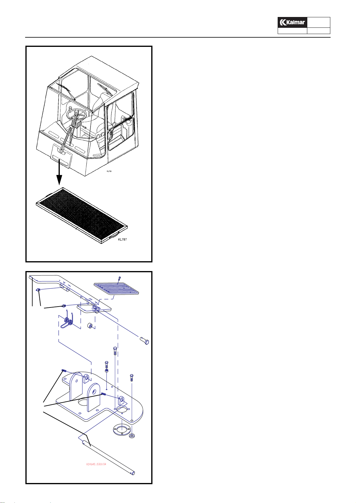
Check and lubrication of brake pedal
(Every 1000:e hours)
1. Check and tighten the loc king screws 3, so that the br ake ped-
2
1
3
4
al is securely fitted in the console.
2. Lubricate the brake pedal shaft through the nipples 2.
1. Brake pedal
2. Lubricating nipple
3. Locking screw
4. Shaft

ContChamp DRD-S
Technical Handbook
Operator’s cab
Service
9407
04-10
S.Grupp 10
12
Windscreen wipers
The wiper arms are fixed to the wiper motor shafts via conical
splines. The shafts are manufactured of hardened steel and the
wiper arm mounting of soft, pressed metal. When fit ting, the nu ts
must be tightened so hard that the splines are pressed well into
the mounting and function as a carrier.
Removal
1. Remove the wiper arms by loosening the nuts and thereafter
tapping and carefully rocking the arms to and fro.
Fitting
1. Check to ensure that the splines on the motor shaft are free
from the softer material from the wiper arm mounting.
1
If this is not the case, clean the splines so that they can
pressed fully into the wiper arm mounting.
2. Fit the wiper arms onto the motor shafts and tighten the nuts
to a torque of 16-20 Nm.
Hold the wiper arm to take up the torque pressure so that it is
not transferred to the motor, which could result in damage
.
IMPORTANT!
2
3
The nuts must be tightened sufficiently hard, otherwise
the shafts may start to slip in side the wiper arm mounti ng,
resulting in damage.
1. Wiper arm fitting
2. Securing nut, wiper arm
3. Grooved cone on motor shaft
4. Wiper motor
4

ContChamp DRD-S
Technical Handbook
1
Air conditioning unit
Description
Air conditioning unit
The air conditioning unit consists of the parts shown in the illustration and its function is to maintain the climate in the operator’s
cab as comfortable as possible. The air conditioning unit:
z heats the air when it is cold
z dehumidifies the air when it is humid
z removes impurities from the air
z cools the air when it is warm
The equipment is controlled by switches and controls on the instrument panel.
5
6
4
9407
04-10
S.Grupp 10
13
1.Heating control
2.Heat exchanger
3.Vapourizer
4.Expansion v alve
5.To condenser
6.To compressor
7.Heating valve
8.From engine
9.To engine
10.Fan
11.Fan
12.Fan control
13.Fresh air filter
14.Air disperser
15.Control defrost/cab
16.Defroster outle t
3
8
9
7
2
15 16
12
14
10
11
13
The heating and ventilating system

ContChamp DRD-S
Technical Handbook
Air conditioning unit
Description
9407
04-10
S.Grupp 10
14
F
2
4
D
C
E
E
3
7
A
B
6
1. Liquid receiver/filter dryer
2. Evaporator
3. Fan
4. Expansion valve
6. Condenser
7. Compressor
1
G
A High-pressure gas
B High-pressure liquid
C Low-pressure liquid
D Low-pressure gas
E Warm air in cab
F Cooled air to the cab
G Outside air for removing heat

ContChamp DRD-S
Technical Handbook
Air conditioning unit
Description
Compressor
The air conditioning system is driven by the compressor. This
performs as a pump, drawing cold, low-pressure gas from the
evaporator, compressing it and thereby raising its temperature,
and discharging it at high pressure to the condenser.
The compressor is driven by V-belts directly from the diesel engine. Switching between operation and idling is controlled by an
electro-magnetic clutch which, in turn, is controlled by a thermostat whose sensor is located between the fins of the evaporator
coil. The thermostat switches off the compressor at low temperatures, to prevent icing of the evaporator.
Condenser
The function of the condenser is to convert the hot high-pressure
gas from the compressor into liquid form. The tubes and fins of
the condenser coil absorb heat, which is then remov ed b y the air
delivered by the fan.
The temperature of the refrigerant in the condenser varies from
about +50°C to +70°C. The pressure varies between 12 and 20
bar, depending on the ambient temperature and the flow of air
through the condenser. When the refrigerant is condensed into
liquid form, it is transferred under pressure to the liquid receiver/
filter dryer.
9407
04-10
S.Grupp 10
15
Liquid receiver with filter-dryer
The function of the liquid receiv er with integrated filter dryer is to
collect the liquid coolant, bind the moisture, and to filter and remove impurities. The receiver, which is located in the condenser
housing, also serves as the expansion v essel in t he refrigeration
circuit.
After flowing through the dryer in the bottom of the liquid receiver ,
the refrigerant flows through a riser tube. A sight glass enables
the operator to check that the liquid flows without the presence
of any bubbles, and that the system is filled with a sufficient
amount of refrigerant.
Expansion valve
The expansion valve throttles the flow and passes an optimised
quantity of refrigerant that the evaporator is capable of ev aporating.
The expansion v alve is also the part of the circuit which separ ates
the high- pressure side from the low-pressure side. The refrigerant flows to the e xpansion valve under hig h pressure and lea v es
it under low pressure.
The amount of refrigerant which passes the evaporator varies,
depending on the thermal load. The valve operates from ’fully
open’ to ’fully closed’ and in-between se arches f or a point to g ive
optimum evaporation.
Evaporator
The heat necessary for evaporating the refrigerant is extracted
from the cab air which is circulat ed b y a fan through the evaporator coil. The cab air is thus cooled, and is distributed and returned
to the cab.
In the ev aporator , the refrigerant re verts to the gaseous state an d
returns to the compressor suction, thereby completing the cycle.

ContChamp DRD-S
Technical Handbook
WARNING!
z If the refrigerant hose should fail or if
other refrigerant leakage should occur ,
switch off the air conditioner immediately.
z Refrigerant is injurious to the skin and
eyes.
z Never release refrigerant in an en-
closed space. If released into a service
pit, for instance, the gas ma y cause asphyxia.
z It is forbidden by law to discharge re-
frigerants into the airintentionally.
z Never carry out welding on a charged
refrigeration system or in its vicinity.
z Only authorised service mechanics are
allowed to drain off and fill refrigerant in
the air conditioning system.
Only the prescribed refrigerant may be
used when refilling.
Air conditioning unit
Service
The liquid refrigerant should be completely evaporated before it
is allowed to flow from the ev aporator. The refrigerant is still cold
even when it has completely evapora ted. The cold v ap our which
flows through what remains of the e vaporator contin ues to absorb
heat, and then becomes overheated. This means that the
temperature of the refrigerant has risen to abo ve th e point where
it evaporates without changing the pressure.
In an evaporator which operates at a suction pressure of 2 bar,
the liquid refrigerant will have a temperature of –1.1°C . When the
refrigerant is subsequently e vaporated through heat absorption
in the evaporator, the temperature of the gas will rise at the evaporator outlet to +1.6°C. This represents a difference of 2.7°C between the evaporation temper ature and the temperature at the
outlet. This is called overheating.
All expansion valv es should be adjusted at the plant in such a wa y
that maximum evaporation with overheating is performed in the
air conditioning system.
Checking the air conditioning unit
If the unit is in continuous operation, this chec k should be carried
out every week from early spring to late autumn and during extended periods of high humidity during the winter.
9407
04-10
S.Grupp 10
16
If the unit is used very little during cold and dry winter periods, th e
compressor should be run for a f e w min utes every week, to lubricate the rubber hoses, couplings, seals and shaft seal.
1. Start the engine and start the air conditioner.
At an outdoor temperature belo w 0°C, the system cannot start
since the low-pressure relay breaks contact.
2. After 10 minutes of operation, check that no bubb les are
visible in the sight glass of the filter-dryer. (Bubbles should
occur only when the compressor is started and stopped.)
If there are any air bubbles, subsequent filling should be performed by an authorised service mechanic.
3. Check that the condenser is not clogged. If necessary, clean
the condenser fins and the fans with compressed air.
4. Change the fresh air filter as necessary.
5. Check the V-belt tension and the compressor mounting.
6. Check that the magnetic coupling engages and disengages
satisfactorily.
7. Check that the condensate drain from the cooling element is
not clogged. Check for leakage.

ContChamp DRD-S
Technical Handbook
IN CAB UNIT CONDENSER UNIT
Air conditioning unit
Service
9407
04-10
S.Grupp 10
17
RD 1,5
A
1
GL 1,5
L
SV 1,5
M
H
RD 1,5
C
4
4
RR
BR 1,5
M
2
3
GL 1,5
VT 1,5
RD 1,5
30
85
8
87
86
BR 1,5
M
M
BR 1,5
7
HIGH
LOW
10
1.Fan switch
2.Cooler on/off
3.Anti-freeze thermostat
4.Resistor
5.Fan motor
6.Indicator lamp – cold (in push button)
7.High-/low-pressure monitor
8.Relay
9.Condenser fan
10.Compressor

Tom sida
Empty page
Leere Seite
Face vide

ContChamp DRD-S
Technical Handbook
Group 20
Electrical system
Contents
9407
04-10
S.Grupp 20
1
Specifications..............................................................2
Electrical system.........................................................3
Description...............................................................3
Checking the electrolyte level of the batter ies .... 5
Fuses..................................................................5
Relays.................................................................6
Bulbs...................................................................7
Starting from another battery..............................8
Air operated operator’s seat................................8
ECS-system
Overview..................................................................9
Terminal ................................................................ 10
Menu structure..................................................10
Operating menues ........................ ....................11
Error messages.................................................15
Service menues ...................... ... .......................20
ECU-processor unit................................................22
Transmission data kit....... .................................23
Engine data kit ........................... .......................23
ECU 1
Functions................................................................24
Circuit board...........................................................26
01 Automatic gear changing .............................27
04 Lever steering ..............................................28
07 Monitoring ....................................................31
ECU 2
Functions................................................................33
Circuit board...........................................................34
Installation, boom.................. .... ... ..........................35
Electric servo..........................................................36
Control lever......................................................37
Pressure sensors right and left lift cylinders ..... 41
Lift - regeneration - lower.................................. 42
Boom extension - regeneration.........................45
Rotation.............................................................49
Twist-locks........................................................51
Side-shift...........................................................53
Length adjustment 20-40’ .................................54
Module 50 Mechanical Overload Protection..........56
Module 51 Vertical lift for Module 50...................... 59
Module 52 Vertical lift + Balance for Module 50.....60
Module 57 Hydraulic Balance ................................ 61
Module 59 Limitation Height/
LC-distance for Module 50/60................................62
Module 60 Electronic Overload Protection.............63
ECU 3
Functions............................................................... 66
Circuit board .......................................................... 67
Module 54 Tilt........................................................ 68
Module 56 Cab movement..................................... 69
Module 61 Support jacks ....................................... 71
Diagrams
Gearchanging systems......................... ... .............. 73
Components, A38630.0100 and A38630.0200......77
ECS overview.................................... ... ... .... ... ....... 78
Electrical diagram explanations............................. 79
Cable markings...................................................... 80
Component list
Electrical diagrams ECS top lift – page
A24925.2000 - 1, 2, 3 A24925.2200 - 1
A24927.2000 - 1, 2 A24927.2200 - 1, 2
A24929.2000 - 1, 2
Electrical diagram, truck body....................A08334.1200
Electrical diagram, inner, standard............A08333.1000
El-servo, singel ECU (S)............................A38630.0100
El-servo, double ECU (S) .......................... A38630.0200
Diagram attachment, 4 pages..............A38414.0100,1-4
Feed ........... ........................ A38414.0100, 1/4
Indication............................ A38414.0100, 2/4
Servo.................................. A38414.0100, 3/4
Working lights..................... A38414.0100, 4/4
Cable to twist-locks.............................. ... ... A38636.0100
Cable feed KDU 791..................................A38415.0100

ContChamp DRD-S
Technical Handbook
Specifications
Alternator rating 1920 W
Starting battery voltage 24 V (2 x 12 V)
capacity 140 Ah
earthing negative
9407
04-10
S.Grupp 20
2

ContChamp DRD-S
Technical Handbook
IMPORTANT!
Always open the main switch whenever work is to be carried out on the
electrical system, if the truck is to
remain idle for some time and whenever welding work is to be carried out
on the truck.
5
4
Electrical system
Description
The system voltage is 24V and the supply is taken from two 12V
batteries connected in series and charged by an alternator
across electronic rectifying and voltage stabilisation circuits.
.
The negative and positive poles are both connected across a
main switch. The negativ e po le is then connected to the chassis.
Warning lamps and instruments are clearly arranged on the in-
strument panel. The central electrical unit with fuses and relays
is located on the lower section of the cab’s rear wall.
3
9407
04-10
S.Grupp 20
3
2
1
1. Main switch
2. 24 V battery
3. Running lights
4. Rear lights
5. Rotating warning light

ContChamp DRD-S
Technical Handbook
Electrical system
Description
9407
04-10
S.Grupp 20
4
34
2
5
6
78
9
1
10
11
12
1. Sensor, outgoing revs (ECS or reversing block)
2. Sensor, gearbox oil temperature, warning lamp and meter
3. Sensor, gearbox oil pressure, warning lamp and meter
4. Main fuses 2 X 50A
5. Relay preheater
6. Sensor, engine oil pressure, warning lamp
7. Sensor, engine oil pressure, meter
8. Sensor, coolant temperature, warning lamp
9. Sensor, coolant temperature, meter
10.Starter motor
11.Sensor, coolant level
12.Alternator
13.Solenoid valve, stop engine
14.Throttle lever, injection pump
15.Sol enoid valve for gear changing
13
14 15
Engine electrics

ContChamp DRD-S
Technical Handbook
Electrical system
Description
9407
04-10
S.Grupp 20
5
N.B.
The starting batteries accompanying
the truck are of the maintenan ce-free
type, which implies that it should not
be necessary to top-up with electrolyte during the life of the batteries.
However, the level of the electrolyte
should preferably be c hecked once or
twice a year. Fill as required by adding de-ionized water.
S1-6 7-12 13-18 19-24 25-30 31-36
KL1749
WARNING!
Never use fuses of a higher amperage
than stated on the lid decal. Risk of
damage or fire.
WARNING!
It is prohibited to connect extra
consumers to any fuse.
B
Checking the electrolyte level of the batteries
The batteries are fitted behind a cov er on the left-hand side of the
truck. The electrolyte level should be about 10 mm above the
cells. Top up with de-ionized water as necessary.
Relay box in cab – fuses
Fuse Rating
No. Circuit protected A
S1 Wiper motor front, direction indicators,
seat buzzer, parking brake sensor............................... 10
S2 Ignition key, preheater, starter motor,
air conditioner, cab lighting ......................................... 15
S3 Container attachment, safety interlock........................ 15
S4 Electric gear-changing ............................................... 5
S5 Warning lamps, instrument illumination, relay,
coolant level .................................................................. 5
S6 Brake lights, reversing lights, reversing alarm ............ 15
S7 Fan (Option: Air condit ioning)
S8 Spare (Option:Container lights)
S9 Working lights (15 A for 4 lamps)
Hazard beacon ........................................................... 10
S10 Working lights, standard (15 A for 4 lamps) ............... 10
S11 Horn, screenwash motor, wiper rear and roof,
wiper front, intermittent relay....................................... 10
S12 Driving lights (main fuse), rear lights
(main fuse), position lights 15
S13 Main beam, right-hand .................................................. 5
S14 Main beam, left-hand..................................................... 5
S15 Dipped beam, right-hand............................................... 5
S16 Dipped beam, left-hand................................................. 5
S17 Rear light, left-hand....................................................... 5
S18 Rear light, right-hand..................................................... 5
S19 ECU1
S20 ECU2........................................................................... 10
S21 Voltage converter .......................................................... 5
S22-S24 Extra........................................................................... –
S25-S30 Extra........................................................................... –
S31 Illumination entry steps, engine compartment
S32 Compressor, air operated chair
S33 electrically operated parking brake............................. 5
S34 Oil cooler, hydraulic oil
S36 Central lubrication
S36 Water separator1) ...................................................... –
1
)Optional equipment
1
)........................................................................ 10
1)
....................................... ............ –
1
).................................. 25
1
)............................... 15
1
)
1)
1)
.............................. –
1)
............................................ –
........ –
A
D
KL593A
Miscellaneous fuses
A Main switch
B Main fuse, boom (1x25 A)
D Main fuse for truck electrical system
Fitted on the engine, 2x50 A

ContChamp DRD-S
Technical Handbook
Electrical system
Description
Relays
305 Reversing light
314 Parking brake, disengagement
315 High power (Starting switch)
316 Wiper motor, front
320 Electric stop (ECS 07)
322 Coolant level (ECS 07)
323 Pulse relay, direction indicators
328 Gear shift (ECS 01)
330 Starting block
331 Propulsion forward
332 Propulsion reverse
334 Clutch release (ECS 01)
367 Lever steering (ECS 04)
322-1 Coolant level
322-2 Coolant level (ECS 07)
399 Spare
Miscellaneous
321-1 Intermittent relay wiper front
321-2 Intermittent relay wiper rear
960 Reversing interlock (excluded at ECS 01)
1
) Optional equipment
1
)
1
)
1
)
1
)
1
)
1
)
1
)
9407
04-10
S.Grupp 20
6
KL 1541

ContChamp DRD-S
Technical Handbook
Electrical system
Description
9407
04-10
S.Grupp 20
7
KL 1542
Bulbs
Rating
Description Watts Base
Instruments 3 BA7s
Indicating lamps 1,2 W2x4,6d
Cab lighting 10 S8,5
Rear lights, red 5 BA15s
Brake lights 21 BA15s
Direction indicators 21 BA15s
Position lights 5 SV8,5
Driving lights (full/dipped beam) 75/70 P43t-38
Reversing lights, white 70 PK22s
Working lights 70 PK22s
Hazard beacon 70 PK22s

ContChamp DRD-S
Technical Handbook
Electrical system
Description
Starting from another battery
Make sure the auxiliary batteries are connected in series, so
that 24 V will be supplied.
N.B. Do not disconnect the truck-battery cables
9407
04-10
S.Grupp 20
8
WARNING!
Batteries emit oxyhydrogen which is
an explosive gas. A spark, for
example from incorrectly connected
starting cables, could cause a battery
to explode and result in serious injury
and damage.
Connect the jumper cables in the following order:
1. Red cable (+) to auxiliary battery
2. Red cable (+) to truck battery
3. Black cable (–) to auxiliary battery
4. Black cable (–) to a location some distance away from
the truck battery, such as the negative cable connection on
the chassis.
Start the engine
Do not disturb the jumper cables while starting, as sparks
may otherwise be caused. Do not lean over either battery.
Disconnect the jumper cables in exactly the reverse order.
1
1. Motor and compressor
Installed in a box on the right hand
side of the machine or beneath the
cab
2. Pressure monitor
3. Fuse 3, 56.3
1
2
Air operated operator’s seat

ContChamp DRD-S
Technical Handbook
ECS
Overview
9407
04-10
S.Grupp 20
9
Kalmar’s ECS - Electronic Control System - is a modular control
and monitoring system to ensure optimum operational security
and total economy . It is possible to combine the system’ s diff erent
modules in a number of different ways.
All vital points of the trucks different systems are connected to
one or several central computer units, ECUs. A terminal display
in the operator’s cab shows current values and generates an
alarm if the values exceed the programmed tolerances.
DRD Container machines are equipped with ECS as standard.
Depending on how respective machines are equipped, one, two
or three ECU central units ma y be fitted.
ECU 1 is used for different additional modules, such as 01 Au -
tomatic Gear Changing, 04 Lever Steering, 06 Mini-steering, 07
Monitoring. See separate descriptions in respective sections.
ECU 2 is obligatory and is used to control the El-Servo cir-
cuits. See the El-Servo section. ECU 2 also functions as
overload protection and for the regeneration system.
ECU 3 is used for machines with modules according to the
table below.
ECU 3
DRD400-60S5
2
1
KL621b-c
1)
ECU 1
01 Automatic
Gear Changing
04 Lever Steering
06 Mini-steering
07 Monitoring
1)
Optional equipment
1)
ECU 2 ECU 3
El-Servo
1)
50 Mechanical over-
1)
1)
load protection
Regeneration
51 Vertical lift
52 Balance + vertical
1)
lift
53 Locking tilt
57 Hydraulic
balance
58 Container
counter
59 Limitation Height/
LC-distance
70 PC/Printer
60 Electronic over-
load protection
Regeneration
V ertical lift
53 Locking tilt
58 Container
counter
59 Limitation Height/
LC-distance
70 PC/Printer
1)
1)
1)
1)
1)
1)
1)
1)
1)
1)
1)
Bottom lift
1)
54 Tilt
55 Pile slope
61 Support jacks
The ECS:
– monitors the engine and gearbox to ensure reasonable
operating conditions
– monitors the components in the system, e.g., sensors, to
ensure their correct function
– provides torque controlled automatic gear ch anging
– interrupts hydraulic functions when ove rload of the steer-
ing axle occurs
– controls the regeneration func tion for boom e xtension and
lift cylinders
– controls vertical lift, balance, pile slope etc.
If a fault occurs:
– a red warning lamp blinks on the terminal
– an error message appears on the terminal display
– The ECS limits the functions of the truck in different ways
depending on the seriousness of the fault. Certain func-
tions are monitored on two le v e ls, whe re le vel 2 limits the
functions of the truck. See the error messages on the ter-
minal display on the following pages.
1)
1)

ContChamp DRD-S
Technical Handbook
1
23
4
F
N
R
1
3
2
4
5
1
2
4
5
ECS
Terminal
9407
04-10
S.Grupp 20
10
Terminal functions
78
KL580B
R
R
3
1. Arr ow left is used to sc ro ll betwee n th e different menus.
2. Arrow right is used to scroll between the different menus.
3. R is used to reset the display after an error message. All errors, with the ex ception of certain lev el 2 errors ca n be reset
by pressing this button. The red warning lamp is then extinguished. The lamp begins to b link again af te r 3-1 0 m inutes,
depending on the fault, if it has not been rectified.
4. - is used to decrease a value.
5. + is used to increase a value.
L
6. ENTER is used to access the service menus and to save
0
new values when setting up and calibrating the system.
Access to the service menus also requires the use of spe cial
codes, that are separately obtainable from Kalmar.
7. A red warning light blinks in the event of an error and is extinguished when reset by pressing button 3.
8. The terminal displa y has 4 lines with space for 20 chara cters
on each line. Graphical presentation of operating menus and
error messages.
Menu structure
There are three types of menu:
1. Operating menus
6
The operating menus are accessible to the operator. The
menus that can be selected depend on how the truck is
equipped and are determined in SETUP. All operating me nus are part of a connected loop. Use arrow RIGHT/LEFT to
move around the loop. The loop also contains:
1.a Overload indicator
Depends on the selected overload protection, module 50/
60.
2. Error messages
Displayed automatically and have priority over other menus.
3. Serv ice menus
The operating menu loop always contains the KALMAR INDUSTRIES SERVICE main menu.The service sub-menus
under this main menu require access to codes that can be
found on a special list from Kalmar. If ENTER is pressed by
mistake in the service menu and the ENTER CODE menu is
displayed, return to the operating menu b y pressing ENTER.
For further information, refer to the respective headings.
KL1409
1.
1a.
1a.
1.
2.
1.
1.
1.
Enter
1.
3.

ContChamp DRD-S
Technical Handbook
01 Automatic gear changing
07 Monitoring
50 Mechanical overload protection system
60 Electronic overload protection system
50
ECS
Terminal
9407
04-10
S.Grupp 20
11
Operating menus
The menus that are displayed on the terminal depend on the
modules with which the truck’s ECS is equipped. The overview
below shows the possible combinations. Use either arrow
RIGHT/LEFT to switch between m enus . All operating men us are
in a connected loop.
Access to the sub-menus under the service menu requires an access code. If ENTER CODE is displayed by mistak e, return to the
operating menu by pressing ENTER.
N.B. Additional menus may occur as a resu lt of adaptation to specific customer requirements.
2
01.50
3
6
5
1
6
5
1
1
10
07.50
01.07.50
5
4
KL1410
6
9
7
Operating menus with mechanical overload protection, module 50
8
Explanations, see next page

ContChamp DRD-S
Technical Handbook
1
ECS
Terminal
Operating menus, module 50
1. Main menu KALMAR INDUSTRIES SERVICE
9407
04-10
S.Grupp 20
12
2
3ab
4ab
5
6
2. Normal operating condition, module 50
a. 1750rpm Engine speed, r/min
a
3. Normal operating condition,
c
c
d
module 50 + module 01
a. 1750rpm Engine speed, r/min
b. F3 Current gear
c. 14 km/h Current speed
4. Normal operating condition,
module 50 + module 01 + module 07
a. 1750rpm Engine speed, r/min
b. F3 Current gear
c. 4 km/h Current speed
d. Fuel level. The tank is full when the indicator is filled to
the right.
5.
Red lamp blinks
The steering axle is overloaded.
It is not possible to switch to other menus until the overload
is rectified.
6. The system interrupts operation. The red warning lamp lights
continuously.
The machine has forward overload.
It is not possible to switch to other menus until the overload
is rectified.
10
a
7
b
a
8
b
a
9
b
a
b
7. a. 75 °C Engine coolant temperature
b. 3.8 bar Engine oil pressure
8. a. 75 °C Gearbox oil temperature
b. 3.8 bar Gearbox oil pressure
9. a. 24.5 v Battery voltage
b. 75 °C Hydraulic oil temperature
10. a. 28756:21.54h Total operating time, tim: min. sek.
b. 130h Time to next service, tim

ContChamp DRD-S
Technical Handbook
60
ECS
Terminal
9407
04-10
S.Grupp 20
13
01.60
07.60
01.07.60
2
3
9
4
4
8
1
1
7
1
3
KL1411
4
Operating menus with electronic overload protection, module 60
5
Explanations, see next page
6

ContChamp DRD-S
Technical Handbook
1
a
2
c
d
e
f
a
3
b
c
d
e
f
a
4
b
c
d
a
b
5
c
d
a
6
ECS
Terminal
9407
04-10
S.Grupp 20
14
Operating menues, module 60
Module 60 overload protectio n function, under normal conditions,
functions as a balance and gives a continual reading of the size
and position of the load.
1. Main menu KALMAR INDUSTRIES SERVICE
2. Normal operating condition, module 60.
a. 1750 rpm Engine speed, r/min
c. 3.0 m Distance between the front edge of the
wheels and the centre of gravity of the load.
d. 25.5 t Current load in ton nes
e. Indicator showing steering axle load, fills the display to the
left for 95-100% of the permitted load. When the indicator
reads full, the system interrupts operation due to overloading
of the steering axle. The red warning lamp blinks.
It is not possible to switch to other menus until the overload
is rectified.
f. Load indicator, fills the display to the right for 0-100%
loads. When the load indicator reads full, the system interrupts operation due to forward overload.
The red warning lamp lights continually.
It is not possible to switch to other menus until the overload
has been rectified.
3. Normal operating condition,
module 60 + module 01 + module 07
a. 1750 rpm Engine speed r/min
b. F3 Current gear
c. d. e. f. See menu 2 explanation above.
4. a. 10.38 t Current load in tonnes
b. 1.07 m Boom extension
c. 3.08 m Lc-distance. Distance between driv e axle
centre and load centre.
d. 23.0 ° Boom angle
5. a. 1750 rpm Engine speed r/min
b. F3 Current gear
c. 14 km/h Current speed
d. Fuel level. The tank is full when the indicator is filled
to the right.
6. a. 75 °C Engine coolant temperature
b
a
7
b
a
8
b
a
9
b
b. 3.8 bar Engine oil pressure
7. a. 75 °C Gearbox oil temperature
b. 3.8 bar Gearbox oil pressure
8. a. 24.5 v Battery voltage
b. 75 °C Hydraulic oil temperature
9. a. 28756:21.54 h. Total operating time, h: min. sec.
b. 130h Time to next service, h

ContChamp DRD-S
Technical Handbook
01 = Automatic gear changing
04 = Leve r steering
06 = Mini Steering
07 = Monitoring
50 = Mechanical overload protection
60 = Electronic overload protection
ECS
Terminal
9407
04-10
S.Grupp 20
15
Error messages
In order of priority. If two faults occur at the same time, the terminal displays the f au lt wit h the h igh est p riority. Error messages always ha ve a higher priority than normal menus.
Errors 01-08 are level 2 errors and cannot be reset prior to the
fault being rectified.
The first two figures to the left of the menu pictur es show to which
module the error message relates.
(These figures do not appear on the display)
01, 07
01, 07
01, 07
01, 07
07
01
02
03
04
05
01. Battery voltage very low/high
Stop as soon as possible and contact service.
02. Faulty signal from accelerator sensor.
Engine speed reduction.
Stop as soon as possible and contact service.
03. Faulty signal from injection pump motor sensor.
Engine speed reduction.
Stop as soon as possible and contact service.
04. Gear lever not functioning.
Engine speed reduction.
Stop as soon as possible and contact service.
05. Engine oil pressure extremely low.
Engine speed reduction.
Stop as soon as possible and contact service.
07
07
07
06
07
08
06. Coolant temperature ext remely high.
Engine speed reduction.
Stop as soon as possible and contact service.
07. Gearbox oil pressure extremely low.
Engine speed reduction.
Stop as soon as possible and contact service.
08. Gearbox oil temperature extremely high.
Engine speed reduction.
Stop as soon as possible and contact service.

ContChamp DRD-S
Technical Handbook
ECS
Terminal
9407
04-10
S.Grupp 20
16
01, 07
07
07
07
07
09
10
11
12
13
09. Faulty signal from engine rev sensor.
Engine speed reduction.
Stop as soon as possible and contact service.
10. Low engine oil pressure.
Check oil level and top up as required.
11. High coolant temperature.
Check coolant le vel and top up as required.
12. Low gearbox oil pressure.
Check oil level and top up as required.
13. High gearbox oil temperature.
Check oil level and top up as required.
07
07
07
07
07
14
15
16
17
18
14. Fuel level extremely low.
Fill the tank to avoid air in the system.
15. Low coolant level.
Top up the coolant fluid.
16. High hydraulic oil temperature.
Operation possible.
Contact service.
17. Faulty signal from fuel gauge sensor.
Operation possible.
Contact service.
18. Faulty signal from gearbox oil pressure sensor.
Operation possible.
Contact service.

ContChamp DRD-S
Technical Handbook
ECS
Terminal
9407
04-10
S.Grupp 20
17
07
07
07
07
07
19
20
21
22
23
19. Faulty signal from engine oil pressure sensor.
Operation possible.
Contact service
20. Faulty signal fro m coolant temperature sensor.
Operation possible.
Contact service.
21. Faulty signal from gearbox oil temperature sensor.
Operation possible.
Contact service.
22. Faulty signal from hydraulic oil temperature sensor.
Operation possible.
Contact service as soon as possible.
23. Service interval exceeded.
Contact service as soon as possible.
01, 07
04
04
06
07
24
25
26
27
28
24. Faulty signal from prop shaft rpm sensor
Engine speed reduction.
Stop as soon as possible and contact service.
25. Steering lever fault.
Switch off the steering system.
Contact service as soon as possible.
26. Faulty signal from steering sensor.
Switch off the steering system.
Contact service as soon as possible.
27. Faulty signal from mini steering sensor.
Switch off the steering system.
Contact service as soon as possible.
28. Warning! Low brake pressure.
Contact service as soon as possible.

ContChamp DRD-S
Technical Handbook
ECS
Terminal
9407
04-10
S.Grupp 20
18
07
60
60
-
-
31
32
50
51
52
31. System fault ECU 1.
Contact service as soon as possible.
32. System fault ECU 2.
Contact service as soon as possible.
50. Battery voltage very low/high.
Contact service as soon as possible.
51. Communication with ECU 3 broken.
Contact service as soon as possible.
52. Communication with ECU 1 broken.
First try switching off and then re-starting the engine!
If the fault remains, contact service as soon as possible.
60
60
50, 60
50, 60
50, 60
53
54
55
56
57
53. Faulty signal from angle sensor
Stop as soon as possible and contact service.
54. Faulty signal from length sensor.
Stop as soon as possible and check the sensor wire.
Contact service if the fault remains.
55. Faulty signal from regeneration sensor.
The regeneration is discontinued.
Contact service.
56. Faulty signal from hydraulic pressure sensors for left lift cylinder. (There is a sensor in both feed and return lines)
Stop as soon as possible and contact service.
57. Faulty signal from h ydraulic pressure sensors f or right lift cylinder. (There is a sensor in both feed and return lines)
Stop as soon as possible and contact service.

ContChamp DRD-S
Technical Handbook
ECS
Terminal
9407
04-10
S.Grupp 20
19
50
50
60
60
58
59
-
60
61
62
58. Faulty analog signal from joystick.
All boom functions are interrupted.
Stop as soon as possible and contact service.
59. Faulty signal from sensor for end position damping
Contact service as soon as possible.
60. Faulty signal from twist-locks sensors.
Applies to both locked and unlo cked position.
The signal from one or more sensors remains on for more
than 60 sec after unlocking of twist-locks.
Check that the contact pins can move freely up and down.
Contact service as soon as possible if the fault remains.
61. System fault.
Load curve is missing.
Stop as soon as possible and contact service.
62. Each one of the Module 60 errors will activate error menu 62.
When error menu 62 is activated:
Warning lamp on the ECS-terminal lights up
When pressing RESET:
Menu 62 starts blinking, 5 sec ON and 5 sec OFF
The hydraulic functions LIFT/LOWER and BOOM OUT/IN
are operative but at a lower speed.

ContChamp DRD-S
Technical Handbook
Detailed descriptions of SETUP,
INITIATION and CALIBRATION can be
found in the separate
ECS SERVICE Handbook
Contact Kalmar
ECS
Terminal
9407
04-10
S.Grupp 20
20
Service menus
All service sub-menus are accessible from the main KALMAR INDUSTRIES SERVICE menu, thereafter, a code must be registered. There are four different codes, codes 1, 2, 3 and 4.
Code 1 leads to the SETUP, INITIA TION and CALIBRA TION
of the modules in ECU1.
Code 2 leads to the INITIATION of the El-servo in ECU 2.
Code 3 leads to the CALIBRATION of module 60 in ECU 2.
Code 4 leads to the DIAGNOSIS menu.
Definition of terms:
SETUP is the setting of the basic values of the machine, def ining,
for example, the modules with which the machine is equipped.
This determines which operational menus then appear.
INITIATION is the basic setting of the diff er ent modules’ par ameters.
CALIBRATION is the individual adjustment of t he max. and min.
values of the different modules’ signals. Calibration is u nique for
each machine.
The illustrations below and on the f ollowing page provide an ov erview of all av ailable service menus. All of them are accessed from
the KALMAR INDUSTRIES SERVICE main menu.
S
10
Code 1
C
IR
N
R
U
TO
ET N
E
TPEU
NTER
SERVICE
20
+-/)
(
0
ITMTO
INTERVAL
N
SERVICE
XETE
ENTE
R
EMU
A
I
A
C
N
U
H
II
T
A
N
ENTE
T
A
T
T
OMAC
E
NG
R
I
I
M
L
S
T
E
E
H
W
O
O
N
M
L
U
D
E
A
G
R
ENTE
21
5
SETUP ECU1
3
4
1
11
9
12
INITIATION
MODULE 01
8
2
3
4
5
6
7
7
1
CALIBRATION
6
KL722-C
MODULE 04
5
4
N
BRATI
IO
A
G
E
R
N
I
E
L
0
1
E
R
I
12
R
D
E
E
N
L
V
A
O
TPOS
N
I
6
11
R
ENTE
R
I
C
B
A
L
A
T
J
I
N
EC
C
A
C
R
E
LE
14
13
10
7
CALIBRATION
I
T
II
A
N
EV
E
L4RENG
N
T
O
I
O
MOT
NI
TO
A
N
A
O
R
R
P
L
EDA
ENTE
INITIATION
MODULE 04
9
8
1
MODULE 01
5
T
ST
I
O
N
M
E
R
D
R
21
0
O
E
L
U
D
I
R
ENTE
3
4
5
6
7
2
3
4
2
3
Service menus
under Code 1

ContChamp DRD-S
Technical Handbook
ECS
Terminal
Code 2 Code 3
9407
04-10
S.Grupp 20
21
16
15
17
18
14
KL723-C
1
19
20
2
SETUP EL-SERVO
ECU2
13
12
11
10
Code 4
1
3
4
5
6
7
8
9
10
9
1
13
14
12
2
3
DIAGNOSIS
8
7
Detailed information about the different
service menu paths can be found u nder respective section descriptions.
The connected loops then appear as
shown in the adjacent picture.
The arrows beside the menus show the
switch paths between men us . Use RIGHT/
LEFT arrow keys.
6
5
16
15
CALIBRATION
MODULE 60
11
4
2
3
4
5
6
7
910
8
Service menus
under Codes 2, 3 & 4

ContChamp DRD-S
Technical Handbook
When replacing the EPROM, always
use Kalmar’s special tools
1
2
KL679
KL678
ECS
ECU - Processor Unit
ECU - processor unit
The computer processor unit receives signals from connect ed
sensors, processes the signals and transmits them to the system’s different controlling organs, such as valves, motors, etc.
Each ECU contains two identical micro-processors. Each microprocessor has its own EPROM that contains the relevant program-ware and parameters for the machine in question. These
EPROMs are marked with the same num ber as the last three
numbers of the corresponding micro-processor number. These
three numbers are used to ensure that the EPR OM is fitted in t he
correct location to match the corresponding micro-processor
when an EPROM replacement is carried out.
Example: The micro-processor has number 80C592. The corresponding EPROM is then number 592 and must be fitted adjacent to 80C592.
Each EPROM has notch at one end and t his should be matche d
with the corresponding notch in the EPROM socket.
Analogue OUT-signals and digital IN-signals are indicated by red
or green LEDs (light emitting diodes). Analogue IN-signals are
not indicated. The LEDs are marked LE1-LE42 and are use d for
fault finding. For each ECU there is a table listing the relevant
junction box pins, the corresponding signal, LEDs and machine
functions. See respective sections.
In the ev ent o f a fault, first investigate the IN-signals. If an IN- signal is incorrect, the fault lies with the sensor and/or ca b les . If, on
the other hand, the IN-signal is correct, the fault lies in the processor.
9407
04-10
S.Grupp 20
22
KL680
N.B. The only permissible action to be take n with the ECU is
the replacement of the EPROM. If this does not rectify the
problem, then the complete ECU, including the housing,
must be replaced with an exchange unit from Kalmar.
3
EPROM = Erasable Programmable Read Only Memory
Kalmar special tools
1, 2 and 3 below, are parts of the ECS kit, art. no. 425817.8068.
1. Extractor.
Art.nr 923827.0002
2. Fittin g tool.
Art.nr 923827.0001
3. Anti-static mat.
The mat should be connected to earth and to one wrist.
Art.nr 923830.0001
4. The EPROM pack.
This must alwa ys be used f or the t ransportation and storage
4
of the EPROM. The pins should be pressed into the plastic
which neutralizes any static electrical charge.
Art.nr923830.0002
KL681

ContChamp DRD-S
Technical Handbook
Data kit
no.
Truck Gearbox No. of
ECS
ECU - Processor Unit
Transmission data kit
Wheel
gears
dimensio
ns
Wheel
radius
Pulses
per rev
9407
04-10
S.Grupp 20
Comments
23
1 DRD 450 36 000
8 DRD 450 18.00x25 0.73 50
9 DRD 450-80X 21.00x35 0.93 50
10 DRD 450-X 18.00x33 0.83 50
16 DRD450-80X 21.00x35 0.93 12
19 DRD 450-X 18.00x33 0.83 12
40 000
4 18.00x25 0.73 12
Engine data kit
Data kit
no.
0 DRD Cummins M11 118 260 Magnetic pick-up
1 VOLVO TD/TWD 30 1023 Volvo-engines without
4 Scania DSI 11 158 194
6 VOLVO TWD1231ME 30 1023 Frequency control
7 VOLVO TWD1030 30 1023 The control motor operates
Truck Engine Model Pulses per
engine rev
Factor Comments
frequency control
inverted
8 Scania DSI 9 22.7 1352 W-connection alternator 65A
9 Scania DSI 11 21.1 1457 W-connection alternator 65A
10 Scania DSI 9 30.3 1014 W-connection alternator 90A
11 Scania DSI 11 28.1 1093 W-connection alternator 90A
13 Scania DI 12 21.1 1457 W-connecti on alternator 65A
14 Scania DI 12 28.1 1093 W-connecti on alternator 90A
15 Cummins 6CT 127 242 Magnetic pick-up
20 Volvo TWD1240VE 38 808 No control motor

ContChamp DRD-S
Technical Handbook
ECU 1
Functions
ECU 1 functions
ECU
Signal LED Function Module
Pin
40 Analogue IN 1. 0-10V Steering lever/Mini-steering signal A x
42 Analogue IN 2. 0-10V
64 Analogue IN 3. 0-10V
65 Analogue IN 4. 0-10V 66 Analogue IN 5. 0-10V 67 Analogue IN 6. 0-10V Servo motor throttle return x
52 Analogue IN 7. 0-10V Accelerator pedal 1 x
1 Analogue OUT 1 LE5 Steering valve left x
3 Analogue OUT 2 x
4 Analogue OUT 3
5 Analogue OUT 4 47 Analogue OUT 5 LE38 (+37) Steering valve right x
69 Analogue OUT 6 LE36 (+35) Servo motor throttle control (pulses to servomotor) x
8 Digital IN 1 LE14 Gear position 1 x x x
9 Digital IN 2 LE17 Gear position 2 x x x
10 Digital IN 3 LE20 Gear position 3 x x x
11 Digital IN 4 LE23 Gear position F x x x
31 Digital IN 5 LE13 Gear position R x x x
32 Digital IN 6 LE16 Brakes/Parking brake active x
33 Digital IN 7 LE19 Level monitor engine cooling system x
34 Digital IN 8 LE22 Seat rotation x
55 Digital IN 9 LE15 Brake pressure x
56 Digital IN 10 LE18 Lever steering ON/OFF. LE18 lights up when the
57 Digital IN 11 LE21 Manual gear change down x
58 Digital IN 12 LE14 Manual gear change up.(Shift MAN/AUT, option) x x
2 Digital OUT 1 LE6 Valve 1 gear changing x x x
24 Digital OUT 2 LE10 Valve 2 gear changing x x x
25 Digital OUT 3 LE7 Valve 3 gear changing x x x
26 Digital OUT 4 LE8 Valve F gear changing x x x
48 Digital OUT 5 LE9 Valve R gear changing x x x
49 Digital OUT 6 LE11 Alarm 1 x
50 Digital OUT 7 LE12 For electric trucks x
22 Digital OUT 8 LE32 (+31) Control for changing be tween steering wheel/lev er
46 Digital OUT 9 LE34 (+33) Direction of servo motor throttle control. LE34 and
Accelerator pedal 2
Wheel return wheel position, steering axle
button for lever steering is in the ON position - a
check that the cable is OK
steering and K lamp contact. LE32 lights red when
lever steering is connected. LE31+LE32 shows
weak light when normal steering is connected (i.e .,
lever steering disconnected)
33 alternate depending on the direction of the motor. When the motor stands still, e .g., when the accelerator pedal is in the upper position, both light
up “weakly” without alternating. Depress the accelerator and check that the LEDs light alt ernately
01 04/06 07
x
x
x
x
x
9407
04-10
S.Grupp 20
24

ContChamp DRD-S
Technical Handbook
ECU
Signal LED Function Module
Pin
6 NTC 1 Engine coolant temperature x
7 NTYC 2 Gearbox oil temperature x
30 NTC 3 Hydraulic fluid temperature x
53 NTC Ambient temperature x
35 Pulse sensor 1 LE28 Engine revs., functions only on Perkins engines x x
59 Pulse sensor 2 LE27 Drive shaft revolutions x x x
60 Pulse sensor 3 + LE25 Steering wheel revolutions, anti-clockwise x
36 Pulse sensor 3 - LE26 Steering wheel revolutions, clockwise. LE25 and
26 will light up alternately, with overlap, when the
steering wheel is turned. Wheel turned anti-clockwise: LE25 lights up first. Wheel turned clockwise:
LE26 lights up first. If not: Check the sensor and
activator on the steering column
27 Rheostat 1 Fuel level x
28 Rheostat 2 Engine oil pressure 10 bar x
51 Rheostat 3 Gearbox oil pressure 25 bar x
ECU 1
Functions
01 04/06 07
x
9407
04-10
S.Grupp 20
25

ContChamp DRD-S
Technical Handbook
ECU 1
Circuit Board
9407
04-10
S.Grupp 20
26
LE1 Should always be lit,indicating a
5V feed from the voltage
transformer
LE29 Not used
LE30 Not used
LE39, LE40 show communication with the ECS ter-
minal. (Applies to the ECU that is connected to
the terminal).
LE39 shows communication from the terminal
and since ECU 1 is “slave” under ECU 2, LE39
should be extinguished.
LE40 shows communication to the terminal
and should blink on all ECUs. If it lights continuously or is extinguished, the program will not
start, i.e., something is wrong, f or example, the
EPROM or electrical supply.
ECU 1 circuit board

ContChamp DRD-S
Technical Handbook
ECU 1
01 - Automatic gear changing
Module 01 - Automatic gear ch anging, is designed f or gearbo xes
with torque converters. The system controls up and down
changing of gears, simplifies operation and extends the service
life of the transmission equipment.
See electrical diagrams.
The system
Prevents t he gears from being engaged if eng ine rev olutions
exceed 1100 rpm
Preven ts changing between f orw ard and re verse gea rs if the
speed of the truck exceeds 3 kpm
Locks the present gear if the signal from the prop shaft rev-
olution sensor is incorret or absent
Reduces engine rev olutions when chan ging to a higher gear
so that the speed of the truck remains constant
Disengages the gearbox if the operator brakes and the
speed of the truck is lower than 3 kph
Provides the required engine revolutions based on the posi-
tion of the accelerator pedal
Continually shows the currently engaged gear on the ECS
terminal display
Function
The point at which the gearbox chan ges gear is optimiz ed to the
truck’s t ransmission equipment. T he torque in the torque conv erter initiates the change of gear. The system changes to a lower
gear when the torque is higher than a pre-programmed value and vice versa.
The operator can limit gear chan ges from 4 to 3, 2 or 1 b y moving
the gear selector to the corresponding position. If the selector is
in the 2nd gear position, the system changes automatically between 1st and 2nd gears.
9407
04-10
S.Grupp 20
27
11
2
5
1. Injection pump motor
2. Electronic accelerator pedal
3. Sensor, gearbox disengagement
4. Sensor, engine revolutions
5. Sensor, propeller shaft revolutions
Fitting and adjustment, see group 40
4
01 Automatic gear changing, included units

ContChamp DRD-S
Technical Handbook
ECU 1
04 - Lever Steering
9407
04-10
S.Grupp 20
28
2
1
KL1405
4 a b 5
04 Lever Steering
See electric diagrams.
The lever steering module is an electrical system for the steering
3
6
of the truck by means of a linear stee ring lever . The steered wheel
deflection is inv ersely proportional to the speed of the truck, i.e., at
low speeds, the steered wheel deflection is greater than at higher
speeds. The system is available with or without wheel return.
With the wheel return system, when the operat or releases th e lever the steered wheels return to a central position.
The steering valve is electronically controlled with one magnet for
right and one for left. This feeds the flow of hydraulic fluid to and
from the steering cylinder. Th e magnets receive analogue signals
from ECU 1.
The standard steering wheel is equipped with two inductive sensors that sense any movement of the steering wheel. The sensors are used to disconnect the lever steering function if the
operator is faced with an emer gency situation. As soon as the
standard steering wheel is used, the lever steering disconnects.
This satisfies the
relevant safety requirements for a wheel-return system.
The sensor that returns the wheels to a central position is located
under a hood adjacent to the steering axle’s left hand king pin.
The lever steering module includes a steering lever console .
7
8
9
1. Steering lever
2. Rocker switch F-N-R
3. Signal horn
4. Switch for gear changing
a. Up
b. Down
(excluded if the truck is
equipped with Module 01)
5. Switch for activating
lever steering
6. Extra function
7. Sensor, steering wheel
speed
8. Control valve, steering
9. Steered wheel sensor
46-49 = Electrical connections
24031
04 Lever steering, included units

ContChamp DRD-S
Technical Handbook
100%
65%
40%
0 5 10 15 Km/hr.
Wheel displacement at full lever
movement.
Values as per INITIATION 04,
menus 3-7
1
2
3
BP1
BP2
BP3
7
8
ECU 1
04 Lever Steering
9407
04-10
S.Grupp 20
29
Lever steering characteristics
Also applies to Module 06, Mini-ste ering
The maximum wheel displacement from maximum lever movement is determined by the speed of the truck. Wheel displacement decreases when speed increases. The reduction in
displacement follows a curve with three break points, see diagram.
This curve determines the steering sensitivity of the truck. The
standard factory setting is as sho wn in the diagram, i.e., full wheel
displacement at 5 kph, 65% displacement at 10 kph and 40% displacement at 15 kph. All of these levels corresponding to full
movement of the steering lever.
It is possible to alter the break points and the displacement , see
INITIATION MODULE 04. One reason for altering lever steering
characteristics can be that a new op erator would like less wheel
displacement at a certain speed - the truck feels “smoother” to
steer. A mor e experienced operator, on the other hand, may like
a quicker steering response, which allows a faster pace of operation.
WARNING!
If wheel displacement is set too high at higher speeds,
there is a risk of the truck tipping. An y alteration of le ver
steering characteristics must be made with great care.
Alteration of the Steering lever output signal
It is possible to alter the output signal from the Steering Lever to
follow two different curves - linear or logarithmic
The logarithmic curve provides less sensitive steering.
7
8
6
5
In the ECS SERVICE Technical Handbook, under Initiation Module 04, a description can be foun d a s to how to choose between
the two curves.
Alteration of the Mini-steering device output signal
The number of turns that corresponds to normal steering wheel
movement can be set, see Technical Handbook ECS SERVICE,
Initiation Module 06.
4
1. Output signal
2. Stop voltage
3. Start voltage
4. Middle position
5. Free-play zone
6. Lever mo vement
7. Linear output signal
8. Logarithmic output signal
LE25
LE26
Anti-clockwise turning: LE25 lights first
Clockwise turning: LE26 lights first
Monitoring of steering lever & wheel angle sensor
If a fault occurs in the lever steering system - sensor, steering lever , cab les - an alarm is generated b y the ECS . L e v er steering is
frozen, i.e., the wheels remain at the current steering angle and
the operator must the refore use the steering wheel. Aft er such a
fault, re-calibra tion must be carried out in accor dance with the instructions in the Calibration section.
Checking the sensors and activator on the steering column
Two sensors on the steering column monitor steering wheel
movement. The senors are activated by an activator with four
cams on the steering column. See the illustration of included
units. When a certain movement of the steering wheel occurs, lever steering is disconnected.
The sensors and activator must be regularly checked during
service. If a fault occurs with the sensors , there is a danger that
the truck will go straight forward.
1. Open ECU 1 so that the LEDs are visible.
2. Locate LE25 and LE26, see ECU 1 Circuit board.
3. T urn the steering wheel and at the same time , check LE25 and
LE26. They should light alternately, with a certain overlap, as
per the curve.

ContChamp DRD-S
Technical Handbook
12 3 45
1. Cover
2. Potentiometer
3. Carrier
4. Locking screw
5. Axle
48 = Electrical connections
ECU 1
06 Mini-Steering
Fitting/Adjustment of wheel angle sensor
Applies only to wheel return system
1. Adjust the wheels so that they are parallel to the truck.
2. Remove the cover of the left hand steering knuckle.
3. Lift off the carrier 3.
4. Loosen the locking screw 4, remove the connections to the
potentiometer and lift it out.
5. Co nn ect a multimeter between the centre pin of the potenti-
ometer and one of the outer pins .
6. Tu rn the potentiometer until the instrument sho ws 2,5 ko hm.
Re-connect the potentiometer.
7. Slide the potentiometer back into the axle 5. Fit the carrier
and tighten the locking screw 4. Fit the cover and seal with
sealing compound.
Calibrate as per T echnical Handbook ECS-SER VICE, Calibration
Module 04.
S.Grupp 20
9407
04-10
30
N.B.
Module 06 Mini-steering has a great deal in
common with Module 04 Lever steer ing.
See section 04 Lever steering.
3
6
2
1
b
4
a
5
Module 06 Mini-Steering
The Mini steering module is an electrohydraulical system for
comfortable steering of the truc k with the arm on the armrest. The
steered wheels follow the position of the Mini steering device. If
the operator releases the Mini steering de vice, both the steering
device and the steered wheels remain in the set position.
The standard steering wheel is equipped with inductive sensors
that sense the moveme nt of the steering wheel. The sensors disconnect the Mini steering if the operator is faced with an emergency situation and starts using the standard steering wheel.
When the Mini steering is disconnected, the lamp in switch 2, see
below, is extinguished.
1. Mini steering device
2. Direction switch F/N/R. The lamp in the switch is alight when
the lever steering is activated
Forwards position = F. Centre position = N
Backwards position = R
3. Signal horn
4. Switches for gear changing, a=UP, b=DOWN
(Excluded if the truck is equipped with module 01 Automatic
gear changing) Press 4a to shift gears 1-2-3- (4) (once for
every gear) and 4b to shift do wn. The gear changing alw a ys
starts with gear 1 on starting and after the direction switch
has passed the N position.
5. Switch for activating Mini steering
Condition: The truck speed must not exceed 3 kph. If the
speed exceeds 3 kph it not possible to activate the Mini
steering. The lamp in switch 2 is alight when the Mini steering is activated
6. Extra function
KL1404

ContChamp DRD-S
Technical Handbook
ECU 1
07 - Monitoring
9407
04-10
S.Grupp 20
Module 07 Monitoring
See electrical diagrams.
The monitoring module checks that the engine and gearbox op-
erate within reasonable limits and thereby prevents a major
breakdown from occurring. The module also monitors the co rrect
function of the different system components, such as sensors,
etc.
V alues, su ch as oil pressure and tempe rature , that are of vital importance when it comes to wear and tear and the risk of breakdown, are monitored on two le vels . A red warning lamp lights and
an error message appears on the terminal display. If the reason
for the f ault is not rectified, the system limits the truck’ s functions .
The most serious faults lead to a reduction in engine re v olutions .
DRD420-60S5
31
4
KL586C
10
8
3
1
6
5
11
7
9
2
1. Sensor, drive shaft revolutions
2. Sensor, engine rev olutions
3. Control motor
4. Sensor , brake pressure
5. Sensor, gearbox oil pressure and oil
temperature
6. Sensor, gearbox oil temperature
7. Sensor, engine oil pressure
8. Sensor, coolant level
9. Sensor, coolant temperature
10.Sensor, hydraulic fluid temperature
11.Sensor, fuel level
07 Monitoring, included units

ContChamp DRD-S
Technical Handbook
ECU 1
07 - Monitoring
9407
04-10
S.Grupp 20
The following signals are monitored:
1. Battery level, min. <14.4 Volts
2. Engine oil pressure, min. level 1 <1.0 bar
3. Engine oil pressure, min. level 2 <0.5 bar
4. Co ola n t tem p erature, max. level 1 >98°C
5. Coolant temperature, max. level 2 >103°C
6. Gearbox oil pressure, min. level 1 <12-15 bar
(dependent on selected transmission data kit)
7. Gearbox oil pressure, min. level 2 <10 bar
8. Gearbox oil temperature, max. level 1 >130°C
9. Gearbox oil temperature, max. level 2 >134°C
10. Fuel level, min.
11. Hydraulic fluid temperature, max. >100°C
12. Coolant level, min.
13. Operating time, max. service interval period, shows the time
remaining to the next service and generates an ala rm when
operating time has been exceeded.
14. Brake pressure
32
The following sensors are checked:
1. Engine revolutions
2. Gear lever
3. Accelerator pedal
4. Fuel injection pump motor
5. Fuel gauge
6. Gearbox oil pressure
7. En gin e oil pr es su re
8. Engine oil temperature
9. Gearbox oil temperature
10. Hydraulic fluid temperature
With non-permissible levels of any of the signals, an alarm is activated - a red warning lamp lights and the terminal display shows
in clear text which signal is incorrect. If any signal begins to approach level 2, engine revolutions are reduced, following a defined curve, to a lower rate of rpm.
The different le vels are pre-prog rammed into the ECU and cannot
be altered.

ContChamp DRD-S
Technical Handbook
ECU 2
Functions
9407
04-10
S.Grupp 20
ECU 2 Functions
Pin no.
ECU 2
S2
8 Digital IN I/O LE14 Working lights, top-lift
9
10
11 “ LE23 C ontrol lever, vertical lift
31 “ LE13 C ontrol lever, twist-locks release (8-9)
32 “ LE16 Twist-loc k s locking/Auto
33 “ LE19 Control lever, doors OK
34 “ LE22 Warning for overloading of steering axle
55 “ LE15 Sensor, activating stop at 30-35’
56 “ LE18 Sensor, activating locking, tilt
57 “ LE21 Overload, mechanical system
58 “ LE24 By-pass connection of safety system
2 Digital OUT PNP I/O LE6 Activating top-lift/loading of hydraulic pump
24 “ LE10 Indication of alignment, on steering wheel panel
25 “ LE7 Indication of twist-locks released, on steering wheel panel
26 “ LE8 Indication of twist-locks locked, on steering wheel pane l
48 “ LE9 Regeneration BOOM OUT
49 “ LE11 Regeneration LIFT
50 “ LE12 Blocking valves, lift cylinders
22 Digital OUT PNP/NPN
46 “ Buzzer, overload and warning of overloaded steering axle
40 Analogue IN 0-10V Boom length
42 “ Control lever LIFT/LOWER P1
64 “ Pressure sensor, right lift cylinder, piston side (mod 60)
65 “ Pressure sensor, right lift cylinder, piston rod side (mod 60)
66 “ Control lever, BOOM OUT/IN P2
67 “ Control lever, ROTATION P3
52 “ Boom angle Min=2V, Max=8V
43 Analogue IN 4-20 mA Pressure sensor, right lift cylinder, piston side (mod 57) +
63 “ Pressure sensor, left lift cylinder, piston side (mod 50, 60)
27 Digital IN 0-196 OHM End position BOOM OUT (mechanical system)
28 “ End position BOOM ANGLE (mechanical system)
51 “ Separate bottom lift (disconn. of tw-loc ks and 20-40’ funct.)
6 Analogue IN 70-120°C
7 “ -20-120°C
30 By-pass of rotation stop
53 “ 70-120°C
1 Analogue OUT pwm PNP1 LE5 Boom IN
3 I1 Boom LIFT
4 I2 Boom LOWER
5 “ PNP4 LE4 Boom OUT
17
18
35 Pulse transmitter 1
59 Pulse transmitter 2
36 Digital IN Rotation stop, counter-clockwise
60 Digital IN Rotation stop, clockwise
23 Battery plus 24V
13 Battery plus 24V
37, 70, 12 Battery minus
Signal LED Function
”
”
LE17 Control lever, side-shift Right (15)
LE20 Control lever, side-shift Left (16)
Pressure sensor, left lift cylinder, piston rod side
(mod 52, 60)
33

ContChamp DRD-S
Technical Handbook
ECU 2
Circuit board
9407
04-10
S.Grupp 20
34
A
LE1 Should always be lit,indicating a
5V feed from the voltage transformer
A Extra circuit board
B Switches, all should be in the ON postion
B
LE39 shows communication from the terminal and
should always blink.
LE40 shows communication to the terminal and
should blink on all ECUs. If it lights continuously
or is extinguished, the program will not start,
i.e., something is wrong, for example, the
EPROM or electrical supply.
ECU 2 circuit board

ContChamp DRD-S
Technical Handbook
ECU 2
Circuit Boards
9407
04-10
S.Grupp 20
Different combinations of ECU
Every ECU has four switches.
Check that the switches are in the positions sho wn in the illustra -
tions.
.
35
ON
OFF
1
234
ON
OFF
ECU 1
1
234
ECU 2
ECU 2
ON
OFF
ECU 2 + A
1
234
1
234
ON
OFF
1
A
234
ON
OFF
A = Extra circuit board
ON
OFF
ON
OFF
1
1
234
234
ECU 3
ECU 3
ON
OFF
1
234
ECU 2
ECU 2
ON
OFF
1
234
ECU 1
KL1795
ECU 2 is always superior
Other ECU’s are “slaves”
1
234
ON
OFF

ContChamp DRD-S
Technical Handbook
X410
ECU 2
Installation boom
9407
04-10
S.Grupp 20
36
KL1533b
KL1533a
KDU 791
KL1536
12
N.B.
The permitted load on KDU 791 is limited.
Therefore, connection of extra equipment
to the KDU is not allowed.
KL1534
KL1535
791 Electronic central unit for top-lift, KDU
1. 10 pol e connection box
3
4
5
6
2. 42 pol e connection box
3. Indicator lamp POWER, green.
lit with 24V feed
4. Indica to r la mp SYSTEM, green
lit when the program registers a
system voltage of 20-29 V
5. Indicator lamp MODE, y ellow
Blinks once a second if the communication
with ECU 2 via CAN bus is correct
6. Indicator lamp STATUS, red
lit when any fault is active.
See error code on the ECS display.
X70 Connection block on boom mounting
X400 Connection block
X401 Connection block
X405 Connection block
X410 Box with relays for emergency stop.
For safety reasons, there are two rela ys connected
in parallel. The relays are controlled from the emer-
gency switch, see 36 on the servo diagram (S)
562 Indicator lamp, red, TWIST-LOCKS RELEASED
563 Indicator lamp, green, TWIST-LOCKS LOCKED
564 Indicator lamp, orange, ALIGNMENT
Electrical installation ECS, boom

ContChamp DRD-S
Technical Handbook
ECU 2
Elservo
9407
04-10
S.Grupp 20
37
El-servo
The el-servo system includes:
Control lever functions for boom movement
All attachment functions
Overload protection
Cab movement
Support jacks
The references in the f ollowing descriptions relate to components
in the el-servo diagrams (diagrams marked S), if nothing to the
contrary is stated.
El-servo (S) A38630.0100 (ECU 2)
El-servo (S) A38630.0200 (ECU2 + ECU 3)
For top-lift circuits, refer to separate diagram.
When following the circuit de scriptions , f irst select an S diagram
and an top-lift diagram that corr espond to the machine in question.
Example: S7 shows component no. 7 on the el-servo diagram,
i.e., the main valve in the hydraulic system.
S50-S65 show the connectors for ECU 2 under operator’s seat.
ANA IN = Analogue IN signal
ANA OUT = Analogue OUT signal
DIG IN = Digital IN signal
DIG OUT = Digital OUT signal
LE1-LE43 = LEDs, with green or red light. These can be located
on the overview illustration of the ECU 2 circuit board.

ContChamp DRD-S
Technical Handbook
ECU 2
Elservo
9407
04-10
S.Grupp 20
38
Control lever
The control lever regulates electrical signals which operate electrohydraulic converters which in turn feeds hydraulic servo pressure to the main valve sections.
The lever han dle is equipped with potentiometers P1–P4 and fo ur
finger-tip controlles switches T1–T4.
The plus feed from the contr ol unit is deliv ererd via sliding shoes
when manoeuvring the machine.
When manoeuvring, the potentiometer setting is altered, and
thus the output signal, in proportion to the lever movement. The
output signal is amplified in the control unit ECU 2 and thereafter
used for controlling the hydraulic servo output from the con verter.
T1 Side shift
1=Left, 2=Right
T2 Unlocking of twist-locks
T3 1=Locking of tilt
2=Locking of levelling
T4 Vertical lift
P1 Lift/Lower
P2 Boom out/in
P3 Rotation
P4 Tilt (Optional)
1. TILT (analogue)
4. Boom OUT/IN (analogue)
8. LIFT/LOWER (analogue)
9. 0-ref. LIFT, EXTENSION, ROTATION
10.10 V feed LIFT, EXTENSION, ROTATION
11.ROTATION CLOCKWISE/ANTI-CLOCKWISE
(analogue)
14.SIDE-SHIFT LEFT/40-20 inwards
15.Feed 24V
16.SIDE-SHIFT RIGHT/20-40 outwards
17.Locking of pile-slope
18.Locking of forward tilt
19.Vertical lift
20.Twist-locks release

ContChamp DRD-S
Technical Handbook
ECU 2
Elservo
9407
04-10
S.Grupp 20
39
Converter
The converter is a electrically controlled pressure reducing v alv e
for the remote control of h ydr aulic functi ons . The out put signal is
a porportional hydraulic servo pressure which is used to control
the spools of the main valves.
The converter consists of a solenoid and a pilot valve. It is connected to the main valve spool actuator block.
The solenoid exerts a proportional force on the pilot valve. The
end of the unit is provided wit h a vent screw and a pushbutton f or
emergency manual operation.
The control pressure output delivered by the pilot v alve to the
spool actuator of the main valve is practically proportional to the
input current.
The pilot valve is closed in the neutral position.
1. Vent screw
2. Push button, manual operation
3. Solenoid
4. Pilot valve
5. Main valve
6. Spool actuator
7. Control current
8. Inlet servo pressure
9. Return servo pressure
A given control current i
servo pressure at the spool actuator
results in a definite
s
Converter

ContChamp DRD-S
Technical Handbook
ECU 2
Elservo
9407
04-10
S.Grupp 20
40
Control lever feed
1. The LIFT/LOWER, BOOM OUT/IN and RO T ATION functions
are fed with 10 V from ECU2, contact S2 (70 pole junction
box on ECU2), pin 45 of connector S55 pin 12. From there
via cable S33 to the D sub-contact S42 on the control lever
S32.
2. Earth refe rence to the 10V is f ed from S2 pin 44 to connector
S55 pin 13. From there via cable S33 to S42 on the control
lever S32.
3. When the lever is in the neutral position P1, P2, P3 and P4
supply 5V to S42 and from there, on to connecto r S55. The
end positions provide 0V and 10V respectively.
4. The SIDE-SHIFT, LOCKING TIL T/PILE SLOPE, STRAIGHT
LIFT AND RELEASE TWIST-LOCKS functions are fed with
24V from fuse 3 of the central electrical unit S1. Via the central electrical unit’s connector 32 pin 3 to the el-servo connector S55 pin 11. Via cab le S33 t o S42 pin 11. From there,
feed to switches T1, T2, T3 andT4.
2
12345678910111213
14 15 16 17 18 19 20 21 22 23 24 25
3
S2
1
6
5
7
1. Control lever
2. D sub-contact for control lever(S42)
3. Cable (S33)
4. Connectors for ECU2 under operator’s seat
5. Earth connections
4
6. CAN bus for communication between ECUs 1-2-3
7. Relays
S2. 70 pole contact for ECU2 (S2)

ContChamp DRD-S
Technical Handbook
Cable S33 of the el-servo system
ECU 2
Elservo
KL 1547
9407
04-10
S.Grupp 20
41
30 = Stop at 30-35’
TW = Twist-locks
S42 = D-sub contact at control lever
S42
U = Lamp, support jacks up
VS = By-pass connection, rotation stop
TP = By-pass connection, Max hight/Min LC-dist
N = Lamp, support jacks down
S = By-pass connection safety system
FB = Front legs, bottom lift
BB = Rear legs, bottom lift
K = Clamping
HS = Cab movement
SB = Support jacks

ContChamp DRD-S
Technical Handbook
ECU 2
Elservo
9407
04-10
S.Grupp 20
42
Sensor in the feed line to left lift cylinder.
Out signal: 4-20 mA
Pressure sensors right and left lift cylinders
N.B. The pressure sensors are different for different modules.
(768-10 and 11 are identical. 768-12, 13 and 14 are identical)
See also the el-servo diagrams (S).
Sensor in the feed line
to right lift cylinder.
Out signal: 4-20 mA
N.B. Module 57, apart
from sensor 768-14,
also includes sensor
768-12 from Module 50
Module 50
Module 57
Sensor in the feedline and returnline to
right and left lift cylinder.
Out signal right sensor: 1-10 V
Out signal left sensor: 4-20 mA
Module 60 (52)

ContChamp DRD-S
Technical Handbook
KL700
S7
S7.1
X69
ECU 2
Elservo
9407
04-10
S.Grupp 20
43
LIFT
See el-servo diagram (S)
1. Control lev er used f or LIFT, P1 gives a 5-9V analogue signal
via 42.8, via cable S33 to X55.1
2. ANA IN S2.42. No indication in ECU2 for analogue IN signals.
3. ANA OUT S2.03. 24V, varies with lever position.
4. X63.1
5. Main valve converter S7.1 opens for servo pressure.
Simultaneous feed of servo pressure to S7.8
6. Main valve sections S7.1 and S7.8 opens for LIFT
Conditions:
1. DIG IN S2.7 . LE19 lit, wh ich m eans :
Cab in rear position
If the cab is in the forward position, doors closed
With remote control - contact OK
Twist-locks either LOCKED or RELEASED
Signal from 791. Control: DIAGNOS, menu 4(8)
No front overload, no steering axle o verload. (Module 50:
LE21 shall be lit. Module 60: No overload indication on the
display)
KL701-D
Regeneration, LIFT
See el-servo diagram (S)
1. 24V to X62.8
2. Connector X69.8, see illustration
Module 50
Conditions for regeneration:
Connects when pressure in lift circuit <85 Bar
Disconnects when pressure is approx. 185 Bar
3. Pressure sensor 768-12.3 in lift cylinder feed IN 24 V, see illustration
4. Pressure sensor 768-12.2 OUT, 4-20 mA, corresponds to 0250 bar pressure in lift circuit
5. X69.5
6. X62.5
7. ANA IN S2.63 (no indication)
(cont’d p.14 next page)
.
KL1418c

ContChamp DRD-S
Technical Handbook
KL1418b
ECU 2
Elservo
9407
04-10
S.Grupp 20
44
Module 60 (or module 52)
Conditions for regeneration:
Connects when pressure in lift circuit <85 Bar
Disconnects when pressure is approx. 185 Bar
8. Feed right sensor: 24V over X69.1 to 768-10.3 and 768- 11.3.
Ref.voltage =0V from X69.2.
9. Feed left sensor: 24V over X69.1 to 768-12.3 and 768-13.3
10. Out signal right pressure side 768-10.2: 1-10V to S19.3
to X62.3, to S2.64 ANA IN (no indication)
11. Out signal right return 768-11.2: 1-10V to X69.4
to X62.4, to S2.65 ANA IN (no indication)
12. Out signal left pressure side 768-12.2: 4-20 mA to X69.5
to X62.5, to S2.63 ANA IN (no indication)
13. Out signal left return 768-13.2: 4-20 mA to X69.6
to X62.6, to S2.43 ANA IN (no indication)
KL1418a
Modules 50,52,60
14. DIG OUT S2.49. LE11 lit (Lever movement >50%)
15. X62.8
16. X69.8
17. Regeneration valves S14, right and left, open an d re gener ation starts.
The regeneration starts with a time-delay which is set in the
SET UP EL-SERVO ECU 2, see Technical Handbook ECS
SERVICE.
18. Earth signal back via X69.2
19. S62.2 to earth
KL702-C
S14

ContChamp DRD-S
Technical Handbook
S7
KL700
S7.2
ECU 2
Elservo
9407
04-10
S.Grupp 20
45
LOWER
See el-servo diagram (S)
1. Control lever used to LOWER, P1 gives a 5-1 V analogue
signal via D sub-contact S42.8, via cable S33 to X55.1
2. ANA IN S2.42. No indication in ECU2 for analogue IN signals.
3. DIG OUT S2.50. (Opens the lift cylinders’ blocking valves
S15). LE12 lit.
4. 24 V to X62.7.
5. X69.7
6. 24 V to the blocking valv es S15, right and left, that open.
7. ANA OUT S2.04 to X63.2
8. Varies 24V between X63.2 and X63.5.
9. Main valve converter S7.2 opens for servo pressure at the
same time servo pressure is fed to S7.8.
10. Main valve section S7.2 and S7.8 opens for LOWER
KL701-D
X69
Conditions:
No alignment indication from attachment, LE14 extin-
guished.
Dead man’s grip activated, LE19 lit.
No front overload, no steering axle overload (Module 50:
LE21 extinguished. Module 60: No overload indication on the
display).
Emergency lowering
In the eve nt of an electrical f a ult that leads t o the b loc king v alv es
on the lift cylinders being unable to be opened, i.e., the boom
cannot be lowered, there is an emergency lowering function.
On the solenoid S15 for the blocking valves (right and left lift cylinders) there is a knob, A in the illustration. Pull this straight out
and turn it one quarter turn and the boom will slowly lower.
KL702-C
S15 A
NOTE: The emergency lowering applies to unloaded machine
only.

ContChamp DRD-S
Technical Handbook
S7
KL700
S7.3
ECU 2
Elservo
9407
04-10
S.Grupp 20
46
BOOM OUT
See el-servo diagram (S)
1. Control lever used to BOOM OUT, P2 gives a 5-9 V analog ue
signal via S42.4, via cable S33 to X55.2
2. ANA IN S2.66.
3. ANA OUT S2.05. LE4 lights depending on voltage.
4. X63.4
5. Main valve converter S7.3 opens for servo pressure.
Simultaneous feed of servo pressure to S7.6.
6. Main valve sections S7.3 and S7.6 opens for BOOM OUT.
Conditions:
1. DIG IN S2.33, LE19 lit.
Safety system not by-passed (S37)
No front overload. (Module 50: LE21 lit. Module 6 0: no o ver-
load indication on the display).
Regeneration, see next page.

ContChamp DRD-S
Technical Handbook
ECU 2
Elservo
9407
04-10
S.Grupp 20
47
KL1418c
X69
Regeneration, BOOM OUT
See el-servo diagram (S)
1. 24V to X62.8
2. Connector X69.7, see illustration.
Module 50
Conditions for regeneration:
Connects when the pressure in lift circuit <85 Bar
Disconnects when the pressure is approx. 185 Bar
.
3. Pressure sensor 768-12.3 for lift cylinder feed IN=24 V, see
illustration
4. Pressure sensor 768-12.2 OUT=4-20 mA, corresponds to 0250 bar pressure in the lift circuit.
5. X69.5.
6. X62.5.
7. ANA IN S2.63 (No indication)
(cont’d p.14 next page)
KL1418b
Module 60 (or module 52)
Conditions for regeneration:
Connects when the pressure in lift circuit <85 Bar
Disconnects when the pressure is approx. 185 Bar
8. Feed right sensor: 24V over X69.1 to 768-10.3 and 768-11.3.
Ref.voltage =0V from S19.2.
9. Feed left sensor: 24V over X69.1 to 768-12.3 and 768-13.3
10.Out signal right pressure side 768-10.2: 1-10V to X69.3
to X62.3, to S2.64 ANA IN (no indication)
11.Out signal right return 768-11.2: 1-10V to X69.4
to X62.4, to S2.65 ANA IN (no indication)
12.Out signal left pressure side 768-12.2: 4-20 mA to X69.5
to X62.5, to S2.63 ANA IN (no indication)
13.Out signal left return 768-13.2: 4-20 mA to X69.6
to X62.6, to S2.43 ANA IN (no indication)
KL1418a

ContChamp DRD-S
Technical Handbook
KL704-D
X67
ECU 2
Elservo
Modules 50, 52, 60
14.DIG OUT S2.48. LE9 lit
15.X61.4
16.Connector X67.4, see illustration
9407
04-10
S.Grupp 20
48
X68
17.Connector X68.4, see illustration
KL705
18. Regeneration valve S18 opens and regeneration
starts
The regeneration starts with a time-delay which is set in the
SET UP EL-SERVO ECU 2, see Technical Handbook ECS
SERVICE.
19.Earth signal to X68.
S18
KL703

ContChamp DRD-S
Technical Handbook
S7
ECU 2
Elservo
9407
04-10
S.Grupp 20
49
BOOM IN
See diagram S.
1. Control lever used for BOOM IN, P2 giv es a 5-1 V anal ogue
signal via S42.4, via cable S33)
2. X55.2.
3. ANA IN S2.66.
4. ANA OUT S2.01. LE5 lit
5. X63.3.
6. Main valve converter S7.4 opens for servo pressure.
Simultaneous feed of servo pressure to S7.5.
7. Main valve sections S7.4 and S7.5 opens for BOOM IN.
KL700
S7.4
Conditions:
DIG IN S2.33, LE19 lit.
Module 60: No steered axle overload indication on the dis-
play.

ContChamp DRD-S
Technical Handbook
KL701-D
X69
ECU 2
Elservo
9407
04-10
S.Grupp 20
Rotation clock wise
See el-servo diagram (S)
Electrical diagram attachments
(A38414.0100 Top-lift)
1. P3 signal 5-9 V out via S42.11.
2. X55.3.
3. ANA IN S2.67 (No indication)
4. ANA OUT S2.2 (LE6 lit)
5. X62.10.
6. X69.10.
7. Activate solenoid valve, top-lift S73 (loadin g of hydraulic
pump).
8. Signal from ECU 2 via CAN bus to KDU Attachment 791.
9. DIG OUT 791.2.2 to 6008
REF OUT 791.2.16 to 6008
50
KL727-D
6008
6009
Conditions:
LE19 lit.
No front overload. (Module 50: LE21 extinguished. Module
60: No overload indication on the display).
Rotation anti-clockwise
1. P3 signal 5-1 V out via S42.11.
2. X55.3.
3. ANA IN S2.67 (no indication)
4. ANA OUT S2.2 (LE6 lit)
5. X62.10.
6. X69.10.
7. Activate solenoid valve top-lift S73 (loading of hydraulic
pump).
8. Signal from ECU 2 via CAN bus to KDU Attachment 791.
9. DIG OUT 791.2.3 to 6009
REF OUT 791.2.17 to 6009.
Conditions:
LE19 lit.
No front overload. (Module 50: LE21 extinguished. Module
60: No overload indication on the display).
N.B.
In attachment function descriptions, the term CAN bus
occurs. The CAN bus in question effects communication,
in the form of a digital pulse stream, between the ECU 2
and 791 computers. These signals cannot be measured
without advanced specialised equipment.

ContChamp DRD-S
Technical Handbook
7202L
X404
7202R
ECU 2
Elservo
9407
04-10
S.Grupp 20
Feed, sensor
1. DIG OUT from 791.2.11 to X402.1, X403.1 and 404.1.
2. Earthing reference REF OUT from 791.2.38 to X402.2,
X403.2 and 404.2.
51
7203L
X402
T5655870-1
X403
7203R
KL1535
Indicator, ALIGNMENT
1. Signal from 7202R to X403.3 to X403.3.
2. DIG IN 791.2.40.
3. Signal from 7203R to X403.6 to X402.6.
4. DIG IN 791.2.26.
5. Signal from 7202L to X404.3 to X402.7.
6. DIG IN 791.2.13.
7. Signal from 7203L to X404.6 to X402.10.
8. DIG IN 791.2.27.
9. Points 1-8 satisfied, gives DIG OUT 791.2.29 to X405.2.
10. Indicator lamp ALIGNMENT lit.
Signal from 791 via CAN bus to ECU 2.
Control: DIAGNOS 4(8).

ContChamp DRD-S
Technical Handbook
KL701-D
6039
X69
6040
ECU 2
Elservo
9407
04-10
S.Grupp 20
52
Twist-locks, automatic locking
1. Feed +24V from central electrical unit S1 connector X38.7.
Condition: Parking brake RELEASED.
2. X51.7.
3. X56.11.
4. Signal in to switch S34, pin 3
5. Switch S34 in AUT position, signal out from pin 7
6. X56.1.
7. DIG IN S2.32, LE16 lit.
Condition: Signal for alignment from 791. Control: DIA GNOS
menu 4(8). Or signal from switch S37 for by-pass of safety
system (DIG IN S2.58, LE24 lit).
8. DIG OUT S2.2, LE6 lit.
9. X62.10
10. X69.10.
11. Activate solenoid valve, top-lift (loading of hydraulic pump).
12. Signal from ECU 2 via CAN bus to 791.
13. DIG OUT from 791.2.37 to 6039791.2.32 to 6040.
REF OUT from 791.2.36 to 6040.
14. Hydraulic feed to twist-lock cylinder that turn the twist-locks
to locked position.
KL727-D
Twist-locks, manual locking
1. Feed +24V from central electrical unit S1 fuse 3 to connector
X32.1.
2. X50.1.
3. X56.4.
4. Main switch S36, on through loop 567 via S35.
5. Switch S34 in MAN position, signal out from pin 2 as for point
6 above.
Twist-locks, release
1. Control lever switch T2 used.
2. 24 V to S42.20.
3. X55.10.
4. DIG IN S2.31, LE13 lit.
Condition: Signal for alignment from 791. Control: DIA GNOS
menu 4(8). Or by-pass of safety system with S37 (DIG IN
S2.58, LE24 lit) and no side-shift, i.e., no signal in to S2.09
(LE17 extinguished) or S2.10 (LE20 extinguished).
5. DIG OUT S2.2, LE6 lit.
6. X62.10
7. X69.10.
8. Activate solenoid valve, top-lift (loading of hydraulic pump).
9. Signal from ECU 2 via CAN bus to 791.
10. DIG OUT from 791.2.23 to 6039.
REF OUT from 791.2.37 to 6039.
11. Hydraulic feed to twist-lock cylinder that turns the twist-locks
to the open position.

ContChamp DRD-S
Technical Handbook
ECU 2
Elservo
9407
04-10
S.Grupp 20
53
7204L
7205L
X404
X402
T5655870-1
X403
7205R
7204R
KL1535
Indicator, twist-locks locked
1. Signal from 7205R to X403.5 to X402.5.
2. DIG IN 791.2.24.
3. Signal from 7205L to X404.5 to X402.9.
4. DIG IN 791.2.23.
5. Points 1-4 satisfied gives DIG OUT 791.2.39 to X405.3
6. Indicator lamp 563 Twist-locks locked lit.
Signal from 791 via CAN bus to ECU 2.
Control: DIAGNOS 4(8).
Indicator, twist-locks released
1. Signal from 7204R to X403.4 to X402.4.
2. DIG IN 791.2.41.
3. Signal from 7204L to X404.4 to X402.8.
4. DIG IN 791.2.22.
5. Points 1-4 satisfied gives DIG OUT 791.2.25 to X405.1
6. Indicator lamp 562 Twist-locks released lit.
Signal from 791 via CAN bus to ECU 2.
Control: DIAGNOS 4(8).

ContChamp DRD-S
Technical Handbook
KL701-D
6021
6020
X69
ECU 2
Elservo
9407
04-10
S.Grupp 20
54
Side-shift left
1. Control lever switch T1 is used for side-shift left.
2. 24 v to S42.14.
3. X55.7.
4. DIG IN S2.10, LE20 lit.
Condition: S2.11 - LE23 extinguished, or S2.56 - LE18 lit,
and S2.31 - LE13 extinguished.
5. DIG OUT S2.2, LE6 lit.
6. X62.10.
7. X69.10.
8. Activate solenoid valve top-lift (loading of hydraulic pump).
9. Signal out from ECU 2 via CAN bus to 791.
10. DIG OUT 791.2.31 to 6020
REF OUT 791.2.35 to 6020
11. 6020 opens for h ydraulic f eed to the side-shift cylinder . Sideshift left.
Side-shift right
1. Control lever switch T1 is used for side-shift right.
2. 24 v to S42.16.
3. X55.8.
4. DIG IN S2.09, LE17 lit.
Condition: S2.11 - LE23 extinguished, or S2.56 - LE18 lit,
and S2.31 - LE13 extinguished.
5. DIG OUT S2.2, LE6 lit.
6. X62.10.
7. X69.10.
8. Activate solenoid valve, top-lift (loading of hydraulic pump).
9. Signal out from ECU 2 via CAN bus to 791.
10. DIG OUT 791.2.30 to 6021
REF OUT 791.2.34 to 6021
11. 6021 opens for h ydraulic f eed to the side-shift cylinder . Sideshift right.
KL727-D

ContChamp DRD-S
Technical Handbook
KL701-D
6018
6019
X69
ECU 2
Elservo
9407
04-10
S.Grupp 20
55
Length adjustment OUT
1. Control lever switches T1 + T4 are used.
T1
2. T1 to th e right.
3. Signal out to S42.16.
4. X55.8.
5. DIG IN S2.09, LE17 lit.
T4
6. T 4 de pr e sse d.
7. Signal out to S42.19.
8. X55.9.
9. DIG IN S2.11, LE23 lit.
10. DIG OUT S2.2. LE6 lit.
11. X62.10
12. X69.10
13. Activate solenoid valve, top-lift (loading of hydraulic pump).
14. Signal out from ECU 2 via CAN bus to 791.
15. Conditions: Signal twist-locks released. Control: DIAGNOS
4(8).
Or signal for by pass connection of safety system with S37
(DIG IN S2.58, LE 24 lit)
16. DIG UT 791.2.4 to 6018
REF UT 791.2.18 to 6018
17. 6018 opens for hydraulic feed to the cylinder, length adjustment OUT begins.
KL727-D
Length adjustment IN
1. Control lever switches T1 + T4 are used.
T1
2. T1 to th e lef t.
3. Signal out to S42.14.
4. X55.7.
5. DIG IN S2.10, LE20 lit.
T4
6. T 4 de pr e sse d.
7. Signal out to S42.19.
8. X55.9.
9. DIG IN S2.11, LE23 lit.
10. DIG OUT S2.2. LE6 lit.
11. X62.10
12. X69.10
13. Activate solenoid valve, top-lift (loading of hydraulic pump).
14. Signal out from ECU 2 via CAN bus to 791.
15. Conditions: Signal twist-locks released. Control: DIAGNOS
4(8).
Or signal for by pass connection of safety system with S37
(DIG IN S2.58, LE 24 lit)
16. DIG OUT 791.2.5 to 6019
REF OUT 791.2.19 to 6019
17. 6019 opens for hydraulic feed to the cylinder, length adjustment IN begins.

ContChamp DRD-S
Technical Handbook
769
X402
T5655870-2
ECU 2
Elservo
9407
04-10
S.Grupp 20
56
End-position damping for IN and OUT length
adjustment
1. Feed, sensor: DIG OUT 791.2.11 to X402.1
Reference voltage, sensor: REF OUT 791.2.38 to X402.2
2. Sig na l from 76 9 to X402 .1 1
3. DIG IN 791.2.12 gives lowered speed at both end positions.
769 Sensor, damping

ContChamp DRD-S
KL1418c
Technical Handbook
ECU 2
50 Mechanical Overload Protection
Module 50 Mechanical Overload Protection
The mechanical overload protection function:
monitors the forward load and generates an alarm on the
ECS terminal.
monitors the rear load on the steering axle.
controls the regeneration system for LIFT and BOOM OUT.
controls the end position damping for LIFT, LOWER and
BOOM OUT.
The mechanical overload protection system consists of (see illustration below)
A pressure sensor, 768-12, in the left lift cylinder fe ed line.
Five inductive sensors for monitoring boom angle, boom ex-
tension and end position.
An inductive sensor on the steering axle suspension to indi-
cate forward overload.
9407
04-10
S.Grupp 20
57
S23a
S72
KL1051
S22
DRD420-60S5
S4
S23b
S24
S21
ECU 2
S2
768-12. Pressure sensor, feed line left
lift cylinder (page 42)
See servo diagram (S)
S2. ECU2
S4. ECS te rminal
S20
See page 59
S20. Sensor, steering axle overload
S21. Sensor, boom angle
S22. Sensor, end position boom angle
S23a. Sensor, boom inner position
S23b. Sensor, boom outer position
KL1058-C
S24. Sensor, BOOM OUT
S72. Relay box, relays for determina-
tion inner or outer boom position
Module 50 Mechanical Overload Protection

ContChamp DRD-S
Technical Handbook
1.
2.
3.
ECU 2
50 Mechanical Overload Protection
Overload indicator
1. Normal operating condition.
2. Steering axle overload
Monitored by two inductive sensors, 24 for boom extension
and 21 for boom angle. When boom extension is less than
1.5 m, the boom angle is greater than 35 ° and 3rd or 4th gear
is engaged both sensors interrupt and gen erate an alarm f or
overload of the steering axle. A re d lamp blinks and the b uzzer sounds intermittently.
3. With forward overload, i.e., when approximately 33% of the
safety margin remains (remaining counter-weight), the red
warning light on the ECS terminal lights up, a buzzer sounds
and the ECS terminal display shows “ov erload”. At the same
time, the system interrupts the LIFT, LOWER and BOOM
OUT functions. Of these, it is possible to make a by-pass
connection of the LOWER fun ction, using the by-pass s witch
on the side of the hydraulic console in the cab .
WARNING!
At any bypassing of th e safety asystem, ext reme care must
be taken when operating the machine.
9407
04-10
S.Grupp 20
58
1
2
1. Chassis
2. Angle-iron activator, activates sensor
Play > 5 mm sensor breaks
3. Hinged linkage
4. Steering axle
S20. Inductive sensor for overload
3
S20
4
The signal for forward overload is supplied by the sensor on the
steering axle suspension. The rear steering axle suspension includes a flexibly mounted hinged linkage with pre-determined
amount of “play”. When the permitted load is exceeded and the
steering axle is the only remaining counter-weight, this play increases the distance between the sensor and the angle-iron that
activates the sensor. When this play is at its maximum, the sensor’s signal ceases, an overload warning is generated an d LIFT,
LOWER and BOOM OUT fun ctions ar e interrupted while BOO M
IN works as usual.
This means that the machine ma y become loc k ed in position. To
rectify such a situation it is possible to mak e a by-pass connection
with the help of the by-pass switch located on the side of the hydraulic console in the cab . Once the by-pass connection is made ,
the BOOM IN and LOWER functions can be used.
Regeneration
Regeneration operates on the LIFT and BOOM OUT functions
and is a system that leads return fluid from the piston sides of the
lift and extension cylinders directly ba ck to the cylinder f eed. The
system is activated at hydraulic pressures lower than 8.5 MPa
and considerably increases the piston speed by increasing the
flow of hydraulic fluid. More rapid boom mo vement can thereby
be achieved on an unloaded machine. The greatest load which
will still allow the regeneration system to be activated is, for example, an empty container in the first row. With a greater load,
LIFT and BOOM OUT function as normal.
The regeneration starts with a time delay which is set in the SETUP EL-SERVO menus, see Technical Handbook ECS SERVICE
End position damping
End position damping reduces the speed of LIFT/LOWER and
BOOM OUT/IN functions in order to reduce jolting at stop positions.
Sensors 22 for boom angle and 23a+b for boom extension are activated before the end positions. The system feeds out less current to the main valves which provide a reduced hydraulic flow
and thereby, a reduction in speed.

ContChamp DRD-S
Technical Handbook
ECU 2
50 Mechanical Overload Protection
9407
04-10
S.Grupp 20
59
S20
S21
S72
S22
S23a
S23b
S18
S24
768-12.Pressure sensor,
feed line left lift cylinder
See also, page 42.
S18. Regeneration valve BOOM OUT
S19. Terminal bar
S20. Sensor, steering axle overload
S21. Sensor, boom angle
S22. Sensor, end position boom angle
S23a.Sensor, boom inner position
S23b.Sensor, boom outer position
S24. Sensor, BOOM OUT
S72. Relay box, relays for determination
inner or outer boom position
Module 50 Mechanical Overload Protection

ContChamp DRD-S
Technical Handbook
LC-Distance = 3.80 m, Distance between the
centre of the drive axle and the centre of
gravity of the load
ECU 2
51 Vertical Lift
9407
04-10
S.Grupp 20
Module 51, vertical lift for Module 50
Module 51 Vertical lift:
steers LIFT/LOWER and BOOM OUT/IN and coor dinates
both of these functions so that the load moves completely
vertically both up or down.
numerically displays WEIGHT, BOOM EXTENSION,
LC-DISTANCE and BOOM ANGLE.
displays the Module 50 o verload men us, as sho wn in the ad-
jacent illustration. The menus vary if additional modules are
selected, for e xample , Printer , Container counter, Automatic
gear changing.
Module 51 consists of: (see illustration below)
A potentiometer type length sensor S17 with wire to indicate
boom extension length.
An oil-filled potentiometer angle sensor S16 that indicates
the lift angle of the boom.
S16 and S17 replace S21, S22, S23a+b , S24 and S72 from
module 50.
When Module 51 is installed, ECU 2 must be initiated. Con-
tact Kalmar to obtain the necessary parameters.
60
S17
S4
S16
DRD420-60S5
KL1060-C
ECU 2
S2
Ses servo diagram (S)
S2. ECU 2
S4. ECS terminal
See group 20 page 66
S16 Angle sensor
S17 Length sensor

ContChamp DRD-S
KL1418b
Technical Handbook
L-TP = 3.0 m, distance between the
front edge of the wheels and
the centre of gravity of the load
LC-DISTANCE = 3.80 m, distance
between the centre of the drive
axle and the centre of gra vity of
the load)
ECU 2
52 Vertical Lift + Balance
Module 52, Vertical Lift + Balance for Module 50
Module 52 Vertical lift + Balance
steers LIFT/LOWER and BOOM OUT/IN and coor dinates
both of these functions so that the load moves completely
vertically both up or down.
numerically displays WEIGHT, BOOM EXTENSION,
LC-DISTANCE and BOOM ANGLE.
numerically displays L-TP and current load in tons.
Note that graphic load indicator only appears on module 60.
displays the Module 50 o verload men us, as sho wn in the ad-
jacent illustration. Overload is indicated by sensor S20 i the
steered axle suspension. The menus vary if additional modules are selected, for example, Printer, Container counter,
Automatic gear changing.
Module 52 consists of: (see illustration below)
A pressure sensor 768-10, 11, 12, 13 in each of the lift cyl-
linder lyftcylinderns feed and return line.
A potentiometer type length sensor S17 with wire to indicate
boom extension length.
An oil-filled potentiometer angle sensor S16 that indicates
the lift angle of the boom.
S16 and S17 replace S21, S22, S23a+b , S24 and S72 from
module 50.
When Module 52 is installed, ECU 2 must be initiated. Con-
tact Kalmar to obtain the necessary parameters.
9407
04-10
S.Grupp 20
61
S17
DRD420-60S5
KL1062-C
768-10, 11, 12, 13 Pressure sensor, left
and right lift cylinder, feedline and return
line. See page 42 Pressure sensor.
See servo diagram (S)
S2. ECU 2
S4. ECS terminal
See page 66
S16. Angle sensor
S17. Length sensor
S4
S16
ECU 2
S2
KL586C
KL1418a

ContChamp DRD-S
Technical Handbook
KL1418c
KL1418d
ECU 2
57 Hydraulic Balance
Module 57 Hydraulic Balance
The hydraulic bala nce is include d in the ECU 2 el- servo system.
The signal to the system comes from the 768-12 pressure sensor
in the left lift cylinder feed and from 768-14, right cylinder.
1. Calibration of the balance must be carried out in accordance
with the instructions in ECU 2 SETUP, points 20 and 21
2. Connect a loaded container to the machine
3. Extend the boom until the red lamp lights.
4. Lift the boom approx. 20 cm ov er the position whe re the red
flags on the left lift cylinder are aligned with each other.
5. Lower the boom until the red flags are exactly aligned with
each other.
(By first lifting the boom too high and then lowering it to the
correct position, the regeneration system is prevented from
building up pressure that can affect the measurement)
9407
04-10
S.Grupp 20
62
KL1412
6. Press the button for weighing
= the vertical lift button on the control lever
7. The result is shown on the ECS terminal display
3
1. Inductive sensor for activation of red
lamp
2
KL1419
1
2. Red lamp for weighing position
3. Feed from the attachment lamp panel
768-12 Pressure sensor in the feed line
to left lift cylinder.
768-14 Pressure sensor in the feed line
to right lift cylinder.

ContChamp DRD-S
Technical Handbook
C
ECU 2
59 Limitation Height/Lc-distance
Module 59 Limitation Height/LC-distance
for module 50/60
In certain cases it may be necessary to limit how high the boom
can be lifted, for example, for operations in areas with overhead
power lines, bridges, traverses, etc, or how close to the cab the
load can be moved.
The pre-set limitation of height or Lc-distance, A on the adjac ent
illustration, can be by-passed using the switch on the hydraulic
control panel (S71)
The switch must be continually pressed in whilst the boom (height
limitation) moves through the area B (700 mm) or the load (limitation of Lc-distance) moves inside limitation A.
Above height C (height limitation), the system functions as normal. In front of limitation A (limitation of Lc-distance) the system
functions as normal.
In parallel with switch S71, the switch for by-passing the safety
system (located on the side of the hydraulic control panel) can
also be used.
Module 59 consists of, see illustration below
Switch S71 for by-passing th e limitation system (height or
Lc-distance)
A potentiometer type length sensor S17 with wire to indicate
boom extension length.
An oil-filled potentiometer angle sensor S16 that indicates
the lift angle of the boom.
S16 and S17 replace S21, S22, S23a+b , S24 and S72 from
module 50.
When Module 59 is installed, the limitation A must be set,
see Technical Handbook ECS SERVICE, CALIBRATION
MODULE 60.
9407
04-10
S.Grupp 20
63
S17
S4
S16
ECU 2
S2
DRD420-60S5
S71
See servo diagram (S)
S2.ECU 2
S4.ECS-terminal
KL1093-C
See page 66
S16 Angle sensor
S17 Length sensor
S71 Switch, height limitation
system by-pass

ContChamp DRD-S
Technical Handbook
ECU 2
60 Electronic Overload Protection
Module 60, Electronic overload protection
The electronic overload protection:
monitors the front load and continually sho ws the r esults via
two different menus on the ECS terminal display, switch between menus using the arrow RIGHT/LEFT keys
monitors the rear load on the steering axle
controls the regeneration system for LIFT and BOOM OUT
includes vertical lift, as standard
includes completely electronic balance, as standard,
measurement precision
measurement area
controls the end position damping of LIFT/LOWER and
BOOM OUT/IN
Electronic overload protection (see illustration below) consists of:
A pressure sensor 768-10, 11, 12, 13 in each lift cylinder
feed and return lines
A potentiometer type length sensor S17 with wire to indicate
the length of extension.
An oil-filled potentiometer type angle sensor S16 to indicate
the lift angle of the boom.
9407
04-10
S.Grupp 20
64
±0.5 tons over 80% of t he complete
S17
1. ECU 1
See servo diagram (S)
2. ECU 2
3. ECU 3
4. ECS terminal
S4
S16
1
S2
S3
DRD420-60S5
ECU 3
2
S
See group 20 page 66
S16.Angle sensor
S17.Length sensor
See page 42 Pressure sensor
768-10, 11, 12, 13 Pressure sensor, left
and right lift cylinder, feed line and
return line
KL1036-C
KL1418b
KL1418a

ContChamp DRD-S
Technical Handbook
XY
Load
ECU 2
60 Electronic Overload Protection
Overload indicator
Under normal circumstances, the overload protection system
functions as a balance and giv es a cont inual read -out of the siz e
and position of the load.
L-TP 4.22M = The distance between the front edge of the wheels
and the centre of gra vity of the load.
23.5 T = Actual load in tons.
X = Load indicator, fills the display to the right for 0-100% loads.
When the load indicator reads full, the system interrupts operation due to forw ard overload. There remains a safety margin of
approx. 33% (remaining counter-weight). The red warning lamp
lights continuously, the warning buzzer sounds continuou sly and
the LIFT, LOWER and BOOM OUT functions are interrupted. Of
these, it is possible to mak e a b y-pass connection to the LO WER
function using the switch on the side of the hydraulic console in
the cab.
9407
04-10
S.Grupp 20
65
Area with 33% safety
remaining
Load curve
X
X
centre of drive axle - centre of load
Distance
Load X, along the whole of the load curve corresponds to maximum reading (100%) on the load indicator X (on the ECS terminal display).
Steering axle overload
Y = Indicator for steering axle load, fills the display to the left for
95-100% of permitted load. When the indicator reads full, i.e.,
with a load of 33 or 43 tons, depending on the t ype of machine,
the red warning lamp on the ECS terminal blinks and the buzzer
sounds intermittently.
Regeneration
The regeneration function operates on the LIFT and BOOM OUT
functions and is a system that directs the return flow of hy draulic
fluid from the piston sides of the lift and extension cylinders, directly back to the cylinder feed. The system is activated at hydraulic pressures lower t han 8.5 MPa and considerably increases
the piston speed by increasing the flow of hydraulic fluid. This
means that much more rapid movement is possible with the machine not under load. The greatest loa d that permits the regeneration system to be activated is, for example, an empty container
on the first row. With a greater load, the LIFT and BOOM OUT
functions operate normally.
The regeneration starts with a time delay which is set in the SETUP EL-SERVO menus, see Technical Handbook ECS SERVICE
End position damping
End position damping reduces the speed of the LIFT/LOWER
and BOOM OUT/IN functions to reduce jolting at stop positions.
The system supplies less current to the main valves which then
provide a reduced flow of h ydra ulic fluid/pressure and thereb y reduce the speed of the above functions.
When calibrating Module 60 define and set the distance from the
stop positions where end position damping is to be activated.

ContChamp DRD-S
Technical Handbook
ECU 2
60 Electronic Overload Protection
9407
04-10
S.Grupp 20
66
S16
S18
S17
S16. Angle sensor
S17. Length sensor
S18. Regeneration valve
768-10. Pressure sensor, feedline right lift cylinder
768-11. Pressure sensor, returnline right lift cylinder
768-12. Pressure sensor, feedline left lift cylinder
768-13. Pressure sensor, return left lift cylinder

ContChamp DRD-S
Technical Handbook
ECU
Pin
8 Digital IN 1 I/O LE14 Parking brake (Remote control)
9 Digital IN 2 I/O LE17
10 Digital IN 3 I/O LE20
11 Digital IN 4 I/O LE23
31 Digital IN 5 I/O LE13
32 Digital IN 6 I/O LE16 Cab movement, FORWARD
33 Digital IN 7 I/O LE19 Cab movement, BACK
34 Digital IN 8 I/O LE22 Cab movement, front and back end po sitions
55 Digital IN 9 I/O LE15
56 Digital IN 10 I/O LE18
57 Digital IN 11 I/O LE21 Remote control
58 Digital IN 12 I/O LE24 Support jacks , change load curve
2 Digital OUT 1 PNP I/O LE6
24 Digital OUT 2 PNP I/O LE10
25 Digital OUT 3 PNP I/O LE7
26 Digital OUT 4 PNP I/O LE8
48 Digital OUT 5 PNP I/O LE9
49 Digital OUT 6 PNP I/O LE11
50 Digital OUT 7 PNP I/O LE12 24 V feed to switch for support jacks
22 Digital OUT 1 PNP NPN
46 Digital OUT 2 PNP NPN
40 Analogue IN 1 0-10V
42 Analogue IN 2 0-10V Lever TILT P4
64 Analogue IN 3 0-10V
65 Analogue IN 4 0-10V
66 Analogue IN 5 0-10V
67 Analogue IN 6 0-10V
52 Analogue IN 7 0-10V
43 Analogue IN 1 0-23mA
63 Analogue IN 3 0-23mA
27 Analogue IN 1 0-196ohm
28 Analogue IN 2 0-196ohm
51 Analogue IN 3 0-196ohm
6 Analogue IN 1 70..120°C
7 Analogue IN 2 -20..120°C
30 Analogue IN 3 -20..120°C
53 Analogue IN 4 70..120°C
1 Analogue UT PWM PNP 1 LE5 TILT OUT
3 Analogue UT PWM PNP 2 LE3 TILT IN
4 Analogue UT PWM PNP 3 LE2
5 Analogue UT PWM PNP 4 LE4
47 Analogue UT PWM PNP/NPN 1 LE38 Cab movement, FORWARD
69 Analogue UT PWM PNP/NPN 2 LE36 Cab movement, BACK
35 Pulse sensor 1
59 Pulse sensor 2
60 Counter
36
Signal Size LED Function
ECU 3
Functions
ECU 3 Functions
9407
04-10
S.Grupp 20
67

ContChamp DRD-S
Technical Handbook
ECU 3
Circuit Board
9407
04-10
S.Grupp 20
68
LE1 Should always be lit, indicates 5V feed to ECU3
from the voltage transformer
LE29 Not used
LE30 Not used
LE39 Should be extinguished
LE40 indicates communication to the terminal and
should blink.
If it lights continuously or not at all, the program
will not start, i.e., something is wrong, for example, the EPROM or power supply
ECU 3 Circuit Board
 Loading...