


Kalmar DRF450 Service Manual

Workshop manual
I§
AForeword
BSafety
CPreventive maintenance
0Complete machine
1Engine
2Transmission
3Driveline/axle
4Brakes
5Steering
6Suspension
7Load handling
8 Control system
9Frame, body, cab and accessories
10 Common hydraulics
11 Common electrics
12 Common pneumatics
DError codes
ESchematics
FTechnical data
GTerminology and index


A F o r e w o r d 1
A Foreword
Table of Contents A Foreword
A Foreword..............................................................................................3
About the Workshop Manual ..................................................................... 3
General .............................................................................................................. 3
Workshop manual contents .............................................................................. 3
References between different information types ............................................ 4
Function group breakdown .............................................................................. 5
Conditions ......................................................................................................... 5
Storage .............................................................................................................. 5
About the machine version .............................................................................. 5
Copyright ........................................................................................................... 6
Reading instructions .................................................................................. 7
Warning information ......................................................................................... 7
Important information ...................................................................................... 7
Read the operator's manual/maintenance manual ......................................... 7
Optional equipment .......................................................................................... 7
Function descriptions ....................................................................................... 8
About the documentation ....................................................................... 11
Documentation sections ................................................................................. 11
Ordering of documentation ............................................................................ 11
Feedback .................................................................................................. 12
Form for copying ............................................................................................. 12
Workshop manual DRF 400–450
VDRF01.01GB

2 A Foreword
VDRF01.01GB
Workshop manual DRF 400–450

A Foreword – A Foreword 3
A Foreword–
A Foreword
About the Workshop Manual
General
Thank you for choosing Kalmar Industries as your machine supplier.
We hope that we'll meet your expectations.
Workshop manual contents
The workshop manual contains information for corrective maintenance (replacement of components) and complements the maintenance manual. Accompanying the workshop manual is supplier
documentation for engine, transmission and drive axle. Where practicable, please refer from the workshop manual to the maintenance
manual and supplier documentation to avoid duplicated information. The workshop manual is divided into the following sections.
AForeword General information about the workshop manual's purpose, contents and
reading instructions as well as survey for feedback of views and any inaccuracies.
BSafety Keep in mind for your safety.
CPreventive maintenance Reference to maintenance manual: Preventive maintenance.
0Complete machine
1Engine
2 Transmission
3Driveline/axle
4Brakes
5Steering
6Suspension
7Load handling
8Control system
9Frame, body, cab and accessories
10 Common hydraulics
11 Common electrics
12 Common pneumatics
DError codes Reference to maintenance manual: Error code information and instructions for
Technical description, comprehensive function descriptions and a description
of the function of components included in the machine, divided into function
groups.
The components used for each function are described under each subfunction. Consequently, common components are described in several places, but
in general under the first function to use the component.
Together with the general description is a detailed description of what is
unique about the specific subfunction. The next subfunction to use the same
component only has a description what is unique for the new function.
Work instructions for corrective maintenance (replacement of components).
reading error code information.
ESchematics Reference to maintenance manual: Wiring and hydraulic diagrams
F Technical data Technical data, conversion tables, information for conversion of units.
G Terminology and index General terminology and abbreviations, explanation of terms and abbrevia-
tions that can appear in the sections, index for headings in the sections.
Workshop manual DRF 400–450
VDRF01.01GB

4 A Foreword– About the Workshop Manual
References between different information types
The maintenance manual and workshop manual are mainly divided
into function groups, see Workshop manual contents page 3. Certain
parts are broken out as separate parts to increase usability, e.g.,
“Technical data”.
The basic rule of searching for information is to use function groups
to find different types of information regarding the function or component in question. As a complement to this, there are references
according to the below.
Function descriptions
(Technical description)
Component descriptions
(Technical description, usually in Workshop manual)
Diagnostic test
(Group 8.4)
Hydraulic diagrams
(Section E)
Error codes
(Section D)
Wiring diagrams
(Section E)
•From Function description to Component description, to enable
fast finding of more information about the different components
that create a function.
•From Function description to Hydraulic diagram, to enable fast
finding of the right hydraulic diagram for the function in question.
•From Component description or Function description to Diagnostic test, to enable fast finding of the right diagnostic menu
that can be used to check the component (only applies to electrical components).
•From Diagnostic test to Wiring diagrams. to enable fast finding
of the right circuit diagram for further troubleshooting.
•From Diagnostic test to Component description or Function description. To enable fast finding of more information about the
component's appearance and position when troubleshooting.
•From Error codes to Diagnostic test, to enable fast finding of the
right diagnostic menu to troubleshoot component or function in
question.
•From Error codes to Function description or Component description, to enable fast finding of more information about components or function.
VDRF01.01GB
Workshop manual DRF 400–450

A Foreword – About the Workshop Manual 5
Function group breakdown
Breakdown into function groups is common for all machines from
Kalmar Industries, down to two-digit heading level (e.g., 4.3 Powerassisted brake system). Machine-unique adaptations of function
groups are done at the third and fourth group levels (e.g., 4.3.9
Wheel brake resp. 4.3.9.1 Disc pack).
This results in certain headings (function groups) being omitted in
the documentation for certain machines since the machine lacks
that particular function. This means that there may be gaps in the
function groups' numbering (e.g., the three-digit heading level 4.8.7
Oil cooler may be included for certain machines, but may be missing
for other machines).
References between manual types (of the type "see Workshop manual DFR 400–450") are used since the different manual types have
different purposes and thus different information content.
References between sections within the same manual are indicated
using section and group number, e.g., "see section 4 Brakes, group
4.3.9 Wheel brake". A reference within the same section is indicated
with page number, e.g., "see Sensor fuel level, description page 24".
Conditions
The instructions are based on the use of generally available standard
tools. All lifting devices, for example, slings, straps, ratchet blocks,
etc., must meet governing national standards and regulations for lifting devices.
Kalmar Industries will not accept any responsibility for modifications
performed without permission from Kalmar Industries or if other lifting devices, tools or work methods are used other than those described in this manual.
Storage
NOTE
The Maintenance Manual should be accessible to the service
personnel.
About the machine version
The information in this publication corresponds to the machine's design and appearance at the time of delivery from Kalmar Industries.
Due to customizations, there may be variations and/or deviations.
Kalmar Industries reserves the right to modify specifications and
equipment without prior notice. All information and data in this manual are valid at the time of publication.
Workshop manual DRF 400–450
VDRF01.01GB

6 A Foreword– About the Workshop Manual
Copyright
Kalmar Industries AB
Duplication of the content in this manual, in whole or in part, is
strictly prohibited without written permission from Kalmar Industries AB.
Duplication by any means such as copying, printing, etc., is prohibited.
VDRF01.01GB
Workshop manual DRF 400–450
A Foreword – Reading instructions 7
Reading instructions
Warning information
Warnings inform on p o tential dangers w h ich can, if the warning s are
not heeded, result in personal injury or product damage.
DANGER
Situation that may result in serious personal injury,
possible death, if the instruction is not followed.
WARNING
Situation that may result in serious personal injury
if the instruction is not followed.
Read the operator’s manual/maintenance manual
Indicates optional equipment
CAUTION
Situation that may result in damage to the product
if the instruction is not followed.
Important information
Important information marked with NOTE facilitates the work process, operation/handling or increases understanding of the information.
NOTE
Information that is important without being safety related.
Read the operator's manual/maintenance manual
The symbol to the left is used in certain cases on the machine and
refers to important information in the operator’s/maintenance manual.
000262
Optional equipment
The symbol to the left is used in the manual to indicate that a function or component is optional equipment. Detailed information on
000264
how the machine is equipped is presented by the machine card enclosed with the spare parts catalogue.
Workshop manual DRF 400–450
VDRF01.01GB

8 A Foreword– Reading instructions
Function descriptions
Function descriptions are schematic overviews that describe how a
function works as well as which components and signals work together.
Function descriptions describe the function in a logical flow from input signal to desired output signal. Most functions require that preset conditions are fulfilled for the function to be activated. In these
cases, the conditions are listed above the illustration.
Function descriptions use symbols to illustrate components such as
valves, sensors, etc.
1
10
9
8
7
2
3
4
5
6
VDRF01.01GB
000520
Example of function description
Workshop manual DRF 400–450

A Foreword – Reading instructions 9
1. Hydraulic force (solid double line)
2. Flag pressure check connection (Check point), indicates that
there is pressure check connection for checking pressure signal
3. Flag diagnostic test, indicates that signal can be checked with
diagnostic test, see group “8.4 Diagnostic test”
4. Illustration of function, (applied brake)
5. Reference to description of component
6. Signal description, reference value for signal out from compo-
nent
7. Description of component's function
8. Position number, reference to position in illustration
9. Position number in illustration, reference to row in table
10. Electric power (solid single line)
Workshop manual DRF 400–450
VDRF01.01GB

10 A Foreword – Reading instructions
Symbol explanation function descriptions
12
34
56
78
M
9 10
11 12
D790-1
13 14
D797-F
15 16
17 18
˚C
19 20
˚C
21 22
Pa
23
˚C
Pa
24
25
26 27
28 29
The following symbols are used in function descriptions, the symbols are based on standard symbols used in wiring and hydraulic diagrams.
1. Electric control signal
2. Electric force
3. Hydraulic control signal
4. Hydraulic force
5. Hydraulic motor
6. Hydraulic oil pump with variable displacement
7. Hydraulic oil pump with fixed displacement
8. Electric motor
9. Accumulator
10. Disc brake
11. Filter
12. Radiator
13. Bulb
14. Control system, two control units with CAN-bus
15. Restriction
16. Adjustable restriction
17. Inductive position sensor
18. Electrically controlled servo valve
19. Thermal by-pass valve
20. Temperature-controlled switch
21. Temperature sensor
22. Pressure sensor
23. Pressure-controlled switch
24. Hydraulic cylinder
25. Double-acting hydraulic cylinder
26. Spring brake cylinder
27. Valve block
28. Shuttle valve
29. Non-return valve
000523
VDRF01.01GB
Workshop manual DRF 400–450

A Foreword – About the documentation 11
About the documentation
Documentation sections
The documentation to the machine comprises the following sections:
Operator's manual
The Operator's manual is supplied with the machine in the cab.
Documentation kit
Maintenance manual and spare parts catalogue with machine card
are supplied with the machine as a separate documentation kit.
Supplementary documentation
There are Supplementary documentation that can be ordered for the
machine in the form of a Workshop manual. The Workshop manual
includes supplier documentation for engine, transmission and drive
axle.
Ordering of documentation
Extra copies and supplementary documentation is ordered from Kalmar Industries.
Kalmar Industries AB
SE-341 81 Ljungby, Sweden.
NOTE
If possible, always indicate publication number when ordering.
Workshop manual DRF 400–450
VDRF01.01GB

12 A Foreword – Feedback
Feedback
Form for copying
Kalmar Industries’ ambition is that you who work with maintenance
of Kalmar machines shall have access to correct information.
Your feedback is important to be able to improve the information.
Copy this form, write down your views and send it to us. Thank you
for your participation!
To: Kalmar Industries AB
Product Support
Torggatan 3
SE-340 10 Lidhult
SWEDEN
Fax: +46 372 263 93
From:
Company / Sender: ..........................................................................................................................................
Manual
information
Suggestions,
views, remarks,
etc.
Telephone: ..........................................................................................................................................................
E-mail: .................................................................................................................................................................
Date: .................................... - .................. - ..................
Name / Publication number: .............................................................................................................................
Section / page number: ......................................................................................................................................
.............................................................................................................................................................................
.............................................................................................................................................................................
.............................................................................................................................................................................
.............................................................................................................................................................................
VDRF01.01GB
.............................................................................................................................................................................
.............................................................................................................................................................................
.............................................................................................................................................................................
Workshop manual DRF 400–450

B S a f e t y 1
B Safety
Table of Contents B Safety
B Safety....................................................................................................3
General safety information ........................................................................ 3
Safety concerns everyone! ............................................................................... 3
A near-accident is a warning signal! ................................................................ 3
Safety instructions ..................................................................................... 4
General .............................................................................................................. 4
Service position ................................................................................................ 4
Hydraulic and brake systems, depressurizing .................................................. 5
Clothing etc. ...................................................................................................... 6
Several mechanics on the same machine ....................................................... 6
Working under machine ................................................................................... 7
Lifting heavy components ................................................................................ 7
Vibrations .......................................................................................................... 8
Noise ................................................................................................................. 8
Solvents ............................................................................................................ 8
Fire and explosion risks .................................................................................... 9
Fluid or gas under pressure ............................................................................ 10
Coolant ............................................................................................................ 11
Refrigerant ...................................................................................................... 12
Air pollution .................................................................................................... 12
Tensioned springs ........................................................................................... 13
Electric motors ................................................................................................ 14
Rotating components and tools ..................................................................... 14
Tyre system ..................................................................................................... 15
Environment ............................................................................................. 16
General ............................................................................................................ 16
Workshop manual DRF 400–450
VDRF01.01S

2 B Safety
VDRF01.01S
Workshop manual DRF 400–450

B Safety – B Safety 3
B Safety–
B Safety
General safety information
Safety concerns everyone!
The safety information concerns everyone who works with the machine! Persons who do not follow the safety instructions given in this
manual must make absolutely sure that the work is performed without risks of personal injury and without risk of damage to machine
or property!
Remember to:
•follow the instructions in this manual
•be trained for the work in question
•follow local laws, safety rules and regulations
•use the correct equipment and tools for the job
•wear the correct clothes
• use common sense and work carefully, do not take any risks!
In this publication, Kalmar Industries has documented and warned
for situations and risks that may occur/exist in connection with operation as well as service/repairs of the truck under normal conditions.
Therefore, its very important that all who work with the truck, or carry out repairs/service work, acquaint themselves with and act according to the information in the maintenance manual and operators
manual.
A near-accident is a warning signal!
A near-accident is an unexpected event where neither persons, machine or property are injured or damaged. However, a near-accident
indicates that there is an injury risk and actions must be taken to
avoid the risk of injuries.
Workshop manual DRF 400–450
VDRF01.01S

4 B Safety– Safety instructions
Safety instructions
General
Read, consider and follow the safety instructions below before starting to work in the machine:
• Service position page 4
• Hydraulic and brake systems, depressurizing page 5
• Clothing etc. page 6
• Several mechanics on the same machine page 6
• Working under machine page 7
• Lifting heavy components page 7
• Vibrations page 8
• Noise page 8
• Solvents page 8
• Fire and explosion risks page 9
• Fluid or gas under pressure page 10
• Coolant page 11
• Refrigerant page 12
• Air pollution page 12
• Tensioned springs page 13
• Electric motors page 14
• Rotating components and tools page 14
• Tyre system page 15
Machine with fully retracted and lowered boom
Service position
General
Service position is used for service, maintenance and other situations when the machine needs to be secured.
Service position means:
•Machine parked, that is, parking brake applied.
•Boom fully retracted and lowered to horizontal position.
•Engine off.
•Main electric power off (with battery disconnector).
003603
VDRF01.01S
Workshop manual DRF 400–450
B Safety – Safety instructions 5
Hydraulic and brake systems, depressurizing
1 Machine in service position, see Service position page 4.
2 Depressurize the hydraulic system.
Turn the start key to position I and activate extension out, a distinct hissing sound is heard if there is pressure in the hydraulic
system. Activate lift, extension and sideshift several times.
3 Turn the start key to position 0 and turn off the main electric
power.
The above illustration shows closed valve.
4 Depressurize the attachment.
Open the relief valve top lift.
002269
Workshop manual DRF 400–450
VDRF01.01S

6 B Safety– Safety instructions
5 Depressurize the brake system by opening the drain valve on
the accumulator charging valve.
NOTE
Keep the drain valve open as long as work is in progress.
Clothing etc.
Clothes should be in good condition. Remove loosely hanging clothing (tie, scarf, etc.). Do not wear clothes with wide sleeves, wide
trouser legs, etc.
Remove jewelry as it may conduct electricity and get caught in moving parts.
Long hair must be tied up securely, otherwise it may easily get
caught in moving parts. Be caref u l when performing w elding work or
work requiring open flames since hair catches fire easily.
Several mechanics on the same machine
WARNING
Be extra careful if several mechanics work on the
same vehicle, so that unintentional movements do
not injury another person. Communicate so that
everyone knows where all are and what they are
doing.
Risks
Work with wheels or axle suspension, mountings, etc. may result in
components on the other side moving and causing damage/injury.
Movements performed from the operator's station, e.g., movement
of lifting equipment, may cause severe personal injuries.
Safety actions
•Make sure that the machine's lifting equipment is completely
lowered or secured in another way.
•Move battery disconnector to position zero, remove the key.
•Be aware of the risks when several persons work around the vehicle.
•Make your co-workers aware of what you’re working with.
•Do not work with drive wheels on the machine's both sides at
the same time.
VDRF01.01S
Workshop manual DRF 400–450
B Safety – Safety instructions 7
001977
Working under machine
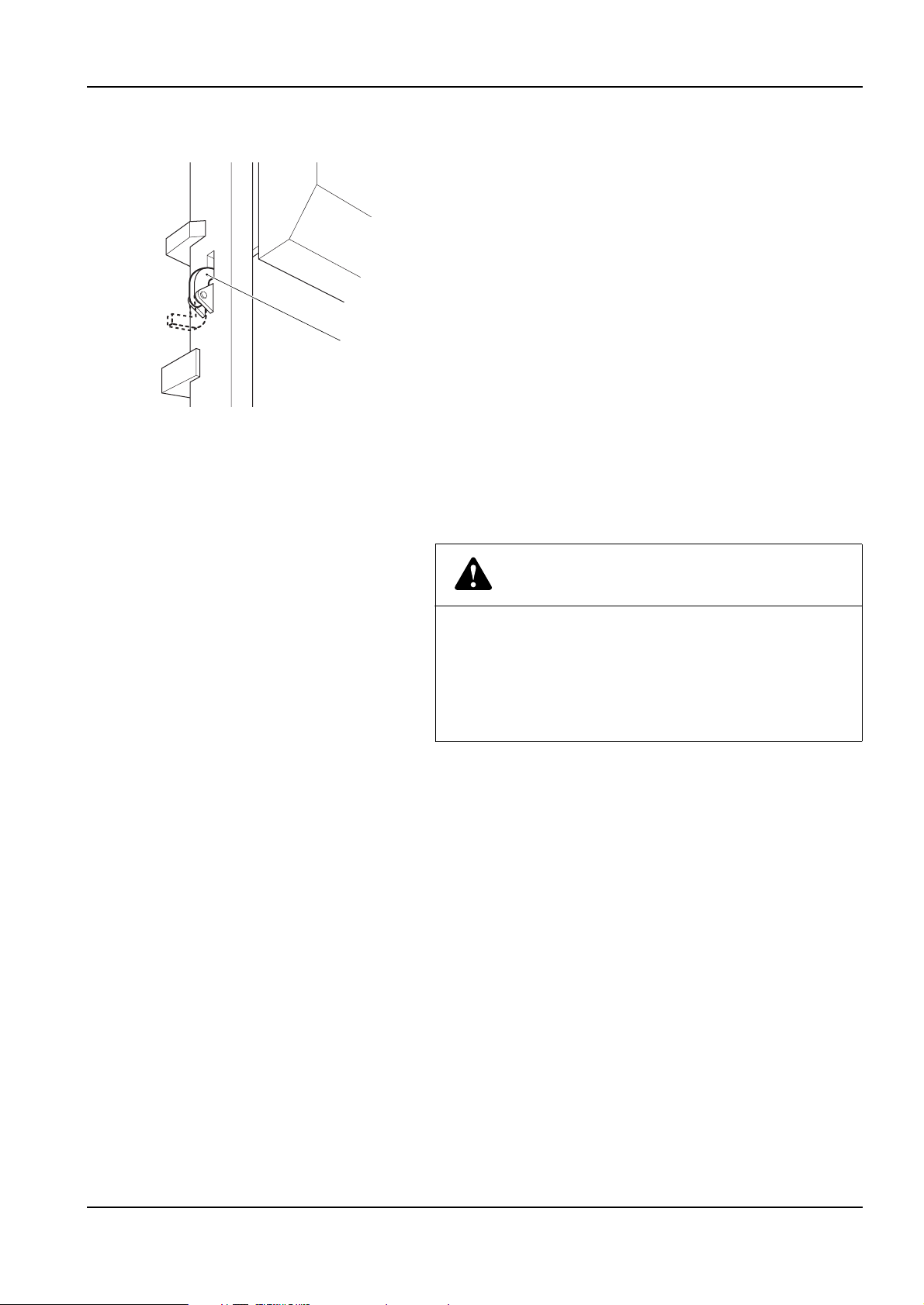
Working under cab
On machines with cab lift the machine shall be secured in raised position with the intended locks.
Working under chassis
A lifted/raised vehicle may under no circumstances be supported or
lifted in parts that belong to the wheel suspension or steering. Always support under the frame or wheel axle.
A
Lock on lift frame for securing cab in raised position.
Risks
Mechanical or hydraulic tools and lifting devices can fall over or accidentally be lowered due to malfunctions or incorrect use.
Safety actions
Use axle stands and supports that stand securely.
Lifting tools should be inspected and type approved for use.
Lifting heavy components
WARNING
Careless handling of heavy components can lead to
serious personal injury and material damage.
Use type approved lifting tools or other devices to
move heavy components. Make sure that the device
is stable and intact.
Risks
Unsuitable lift slings, straps, etc. may break or slip.
The centre of gravity (balance point) of the component can change
during the course of the work, and the component may then make
unexpected movements which may cause severe personal injuries
and material damage.
A component lifted with lifting equipment can start to turn if the
equilibrium is upset.
A component lifted using an overhead crane may start to swing back
and forth, which can cause severe crushing injuries or material damage.
Workshop manual DRF 400–450
VDRF01.01S

8 B Safety– Safety instructions
Safety precautions
Lift using a lifting device. Use lifting tools or equipment, espe-
cially when such equipment is available for specific work operations.
See the workshop manual for methods.
If lifting must be performed without lifting device:
•Lift near the body.
•Keep your back vertical. Raise and lower with legs and arms, do
not bend your back. Do not rotate your body while lifting. Ask for
assistance in advance.
•Wear gloves. They're good protection against minor crushing injuries and cuts to fingers.
•Always use protective shoes.
Vibrations
In case of long-term use of vibrating tools, for example, impact nut
runners or grinders, injuries may be sustained as vibrations can be
transmitted from tools to hands. Especially when fingers are cold.
Safety actions
Use heavy gloves to protect against cold and somewhat against vibrations.
Switch between work duties to give the body time to rest.
Vary work position and grip so that the body is not stressed in only
one position by the vibrations.
Noise
Noise louder than 85 dB (A) that lasts for longer than 8 hours is considered harmful to hearing. (Limit values may vary between different
countries.) High tones (high frequencies) are more damaging than
low tones at the same sound level. Impact noise can also be hazardous, e.g. hammer blows.
Risks
At noise levels higher than the limits hearing damage can occur. In
more severe cases, hearing damage can become permanent.
Safety precautions
Use hearing protection. Make sure that it is tested and protects
against the noise level in question.
Limit noise with noise-absorbing dividers, for example, noise-absorbing materials in roof and on walls.
VDRF01.01S
Solvents
Fluids that (as opposed to water) dissolve grease, paint, lacquer,
wax, oil, adhesive, rubber, etc. are called organic solvents. Examples: White (petroleum) spirits, gasoline, thinner, alcohols, diesel, xylene, trichloroethylene, toluene. Many solvents are flammable and
constitute a fire hazard.
Workshop manual DRF 400–450

B Safety – Safety instructions 9
Risks
Products containing solvents produce vapors that can cause dizziness, headaches and nausea.They may also irritate mucous membranes in the throat and respiratory tracts.
If the solvent comes into direct contact with the skin, this may cause
drying and cracking.Risk for skin allergies increases. Solvents may
also cause injury if they penetrate through the skin and are absorbed
by the blood.
If the body is continuously exposed to solvents, the nervous system
may be damaged. Symptoms include sleep disorders, depressions,
nervousness, poor memory or general tiredness and fatigue. Continuous inhalation of gasoline and diesel fumes is suspected to cause
cancer.
Safety precautions
Avoid inhaling solvent fumes by providing good ventilation, or wearing a fresh-air mask or respiratory device with a suitable filter for the
toxic gases.
Never leave a solvent container without tight-sealing lid.
Use solvents with low content of aromatic substances. This reduces
the risk of injuries.
Avoid skin contact.
Use protective gloves.
Make sure that work clothes are solvent-resistant.
Fire and explosion risks
Examples of explosion-prone substances are oils, petrol, diesel fuel,
organic solvents (lacquer, plastic, cleaning agents), rust proofing
agents, welding gas, gas for heating (acetylene), high concentration
of dust particles of combustible materials. Rubber tyres are highly
flammable and cause fires that spread explosively.
Risks
Examples of causes of ignition include welding, cutting, smoking,
sparks produced by grinding, inflammable materials coming into
contact with hot machine parts, the generation of heat in rags saturated with oil or paint (linseed oil) and oxygen.Oxygen cylinders,
lines and valves must be kept free from oil and grease.
Fumes from gasoline, for example, are heavier than air and can thus
“run down” a sloping grade, or down into a grease pit, where welding flames, grinding sparks or a burning cigarette can cause an explosion. Evaporated gasoline has a very powerful explosive force.
Workshop manual DRF 400–450
VDRF01.01S

10 B Safety – Safety instructions
Special cases
Diesel fuel oil with an additive of petrol has a reduced flash point. Explosion risk even at room temperature. The explosion risk due to
warmed diesel fuel oil is greater than for gasoline.
When changing oil in the engine, hydraulic system and transmission,
keep in mind that the oil may be hot and can cause burn injuries.
Welding on or near the machine. If diesel or other oils have leaked
out and have been absorbed by rags, absorbing agent, paper or other porous material, glowing welding sparks can cause ignition and
an explosive spread of fire.
When a battery is being charged, the battery electrolyte water is divided into oxygen and hydrogen gas. This mixture is very explosive.
The risk of explosion is especially high when a booster battery or a
rapid-charge unit is used, as these increase the risk of sparks.
The machines nowadays contain a lot of electronic equipment. During welding work, the control units must be disconnected and current turned off using the battery disconnect switch. Otherwise,
strong welding currents can short-circuit the electronics, destroy expensive equipment, and may also cause an explosion or fire.
Welding work must never be carried out on painted surfaces (remove paint by blasting at least 10 cm around the welding or cutting
point.) Use gloves, breathing protection and protective safety glasses. Also, welding work must never take place near plastic or rubber
materials without first protecting them from the heat. Paints, plastics and rubber generate various substances when heated that may
be hazardous to health. Be careful with machines that have been exposed to intense heat or a fire.
Safety precautions
Store hazardous substance in approved and sealed container.
Make sure that there is no ignition source near flammable or explosive substances.
Make sure that ventilation is adequate or there is an air extraction
unit when handling flammable substances.
VDRF01.01S
Fluid or gas under pressure
High-pressure lines can be damaged during work, and fluid or gas
can stream out.
There may be high pressure in a line even if the pump has stopped.
Therefore, gas or fluid can leak out when the connection to the hose
is loosened.
A gas cylinder subjected to careless handling can explode, for example, if it falls onto a hard surface. Gas can stream out through damaged valves.
Workshop manual DRF 400–450

B Safety – Safety instructions 11
Risks
There are injury risks in connection with work on:
•Hydraulic system (for example, working hydraulics and brake
system).
•Fuel system.
• Tyre repairs.
•Air conditioning.
Safety precautions
•Use safety glasses and protective gloves.
•Never work in on a pressurized system.
•Never adjust a pressure limiting valve to a higher pressure than
recommended by the manufacturer.
•A hydraulic hose that swells, for example, at a connection, is
about to rupture. Replace it as soon as possible! Check connections thoroughly.
•Use fluid when checking for leaks.
•Never blow clothes clean with compressed air.
•Discarded pressure accumulators must first be punctured before they are deposited as waste (to avoid risk of explosion).
Carefully drill a hole with 3 mm diameter after depressurizing.
• Never use your hands directly to detect a leak.A fine high-pressure stream from a hydraulic hose can easily penetrate a hand
and causes very severe injuries.
Coolant
The coolant in the machine’s cooling system consists of water, anticorrosion compound and (when needed) anti-freeze fluid, for example, ethylene glycol.
Coolant must not be drained into the sewer system or directly onto
the ground.
Risks
The cooling system operates at high pressure when the engine is
warm. Hot coolant can jet out and cause scalding in case of a leak
or when the expansion tank cap (filler cap) is opened.
Ingesting ethylene glycol and anti-corrosion compound is dangerous
and hazardous to health.
Safety precautions
•Use protective gloves and safety glasses if there is a risk of
splashing or spraying.
•Open the filler cap first, to release the excess pressure. Open
carefully.Hot steam and coolant can stream out.
•If possible, avoid working on the cooling system when the coolant is hot.
Workshop manual DRF 400–450
VDRF01.01S

12 B Safety – Safety instructions
Refrigerant
Refrigerant is used in the machines air conditioning.
Work on the air conditioning system must be performed by accredited/authorized and trained personnel according to national legislation and local regulations.
Risks
The air conditioning operates at high pressure. Escaping refrigerant
can cause freeze burns.
Heated refrigerant (e.g. during the repair of leaks in the A/C system),
produces gases that are very toxic if inhaled.
Safety precautions
•Use special instructions and equipment for refrigerant according to the workshop manual when working on the air conditioning system. Special certification and authorization must be held
by personnel permitted to do the work. (Follow national legislation and local regulations!)
•Use protective gloves and safety glasses if there’s a risk of leaks.
•Make sure that heat-producing sources or objects are not close
by (cigarette glow, welding flame).
Air pollution
Air pollution is the impurities in the air around us and which are regarded as hazardous to health. Certain pollution is more prominent
in certain environments.
The following health-hazardous air pollution is especially prominent
in workshops:
• Carbon monoxide (fumes) is present in exhaust fumes.
Odorless and therefore especially dangerous.
• Nitrogen oxides (nitrous gases) are present in exhaust
fumes.
• Welding smoke especially hazardous to health when welding
on oily surfaces, galvanized or lacquered materials.
• Oil mist for example, when applying anti-corrosion agent.
• Grinding dust and gases generated when grinding and heat-
ing plastics, lacquer, anti-corrosion agents, lubricants, paint,
etc.
• Isocyanates are present in certain paints, fillers, adhesives
and foam plastics used on machines.
VDRF01.01S
Workshop manual DRF 400–450

B Safety – Safety instructions 13
Risks
Sulphuric acid mist is corrosive and injures the respiratory tracts.
(Generated when heating certain plastics and paints.)
Isocyanates can be released in the form of steam, dust (or may be
present in aerosols) when cutting, grinding or welding. Can irritate
mucous membranes producing symptoms similar to asthma and impairing lung function. Even brief exposure to high concentrations
can give problems with persistent high sensitivity.
Safety precautions
•Make sure of adequate ventilation with fresh air when welding,
battery charging and other work when ha zardous g ases are generated.
•Use suitable gloves and breathing protection when there’s a risk
of oil mist. Make sure that protective gear is oil-resistant.
•Apply oil-resistant protective lotion to unprotected skin.
•Make sure that an eye-wash station is in the immediate vicinity
when working with corrosive substances.
•Avoid unnecessary operation of the machine inside the workshop. Connect an air extractor to the exhaust pipe so that the
exhaust fumes are removed from the workshop.
Tensioned springs
Examples of tensioned springs:
1. Torque springs in pedals for example.
2. Return spring (cup springs) in parking brake cylinder.
3. Lock rings
4. Gas springs
Risks
If a tensioned spring releases, it is shot out by the spring force and
can also take adjoining parts with it.
Small springs can cause eye injuries.
Parking brake springs are tensioned with high force and can cause
very severe accidents if they are accidentally released in an uncontrolled manner.
Gas springs and gas-charged shock absorbers are tensioned with
high force and can cause very severe accidents if they are accidentally released in an uncontrolled manner.
Safety precautions
•Use safety glasses.
•Lock rings should be of a suitable type and in good condition.
•Follow the instructions in this and other manual when performing maintenance and changing parts and components.
•Always use recommended tools.
Workshop manual DRF 400–450
VDRF01.01S

14 B Safety – Safety instructions
Electric motors
Safety actions
Always turn off the battery disconnector when working on electric
motors.
Always block the machine’s wheels, make sure that the parking
brake is activated and that the gear selector is in neutral position before starting any work on the machine.
Rotating components and tools
Examples of rotating components and tools:
•Cooling fan
•Drive belts
•Drive shafts
•Drills
•Grinders
Risks
Rotating components, for example, fans or shafts, can cause severe
injuries if touched.
Drills, lathes, grinders or other machines with rotating parts can
cause severe accidents if clothes or hair get caught and are wound
up in the machine.
Safety precautions
•Do not use gloves when working with a drill.
•Remove loose, hanging clothing, scarf or tie.
•Never use clothing with wide sleeves or trouser legs.
•Make sure that clothing is intact and in good condition.
•Long hair should be gathered up in a hair-net or similar.
•Remove large or loose hanging jewellery from hands, arms and
neck.
VDRF01.01S
Workshop manual DRF 400–450

B Safety – Safety instructions 15
Tyre system
DANGER
Tyres should be regarded as pressurized containers.
They constitute fatal danger if handled incorrectly.
Parts can be thrown with explosive force and may
cause severe injuries.
Never repair damaged tyres, rims or lock rings. Tyre
repairs should only be performed by authorized personnel.
Risks
Dismantling wheels: Tyres, rims or lock rings can be thrown.
Inflating tyres: Tyres, rims and lock rings can be thrown.
Safety actions
•Deflate the tyre before starting to work on the wheel.
•Check that tyres, rims and lock rings aren’t damaged. Never repair damaged rims or lock rings.
•Use protective screen and safety glasses.
Workshop manual DRF 400–450
VDRF01.01S

16 B Safety – Environment
Environment
General
Ever-increasing industrialisation of our world is having a significant
impact on our global environment. Nature, animals and man are subjected daily to risks in connection with various forms of chemical
handling.
There are still no environmentally safe chemicals, such as oils and
coolants, available on the market. Therefore, all who handle, perform service on or repair machines must use the tools, assisting devices and methods necessary to protect the environment in an
environmentally sound manner.
By following the simple rules below, y ou will contribut e to protecting
our environment.
Recycling
Deposit discarded materials for recycling or destruction.
Environmentally hazardous waste
Components such as batteries, plastics and other items that may
constitute environmentally hazardous waste must be handled and
taken care of in an environmentally safe and sound manner.
Discarded batteries contain substances hazardous to personal
health and the environment. Therefore, handle batteries in an environmentally safe manner and according to national regulations.
Oils and fluids
Oils freely discharged cause environmental damage and can also be
a fire hazard. Therefore, when emptying and draining oils or fuel,
take appropriate action to prevent unnecessary spills.
Waste oils and fluids must always be taken care of by an authorised
disposal company.
Pay close attention to oil leaks and other fluid leaks! Take immediate
action to seal the leaks.
Air conditioning system
The refrigerant in the air conditioning system for the cab adds to the
greenhouse effect and may never be intentionally released into open
air. Special training is required for all service work on the air conditioning system. Many countries require special certification by an
authority for such work.
Working in a contaminated area
Used cab and engine air filters from machines operating in conditions with asbestos dust, or other hazardous dust, must be sealed in
air-tight plastic bags before being deposited in the designated area.
The machine must be equipped for work in a contaminated area (environmentally contaminated or hazardous to personal health) before
work is started. In addition, special local regulations apply when
handling and servicing such a machine.
VDRF01.01S
Workshop manual DRF 400–450
 Loading...