

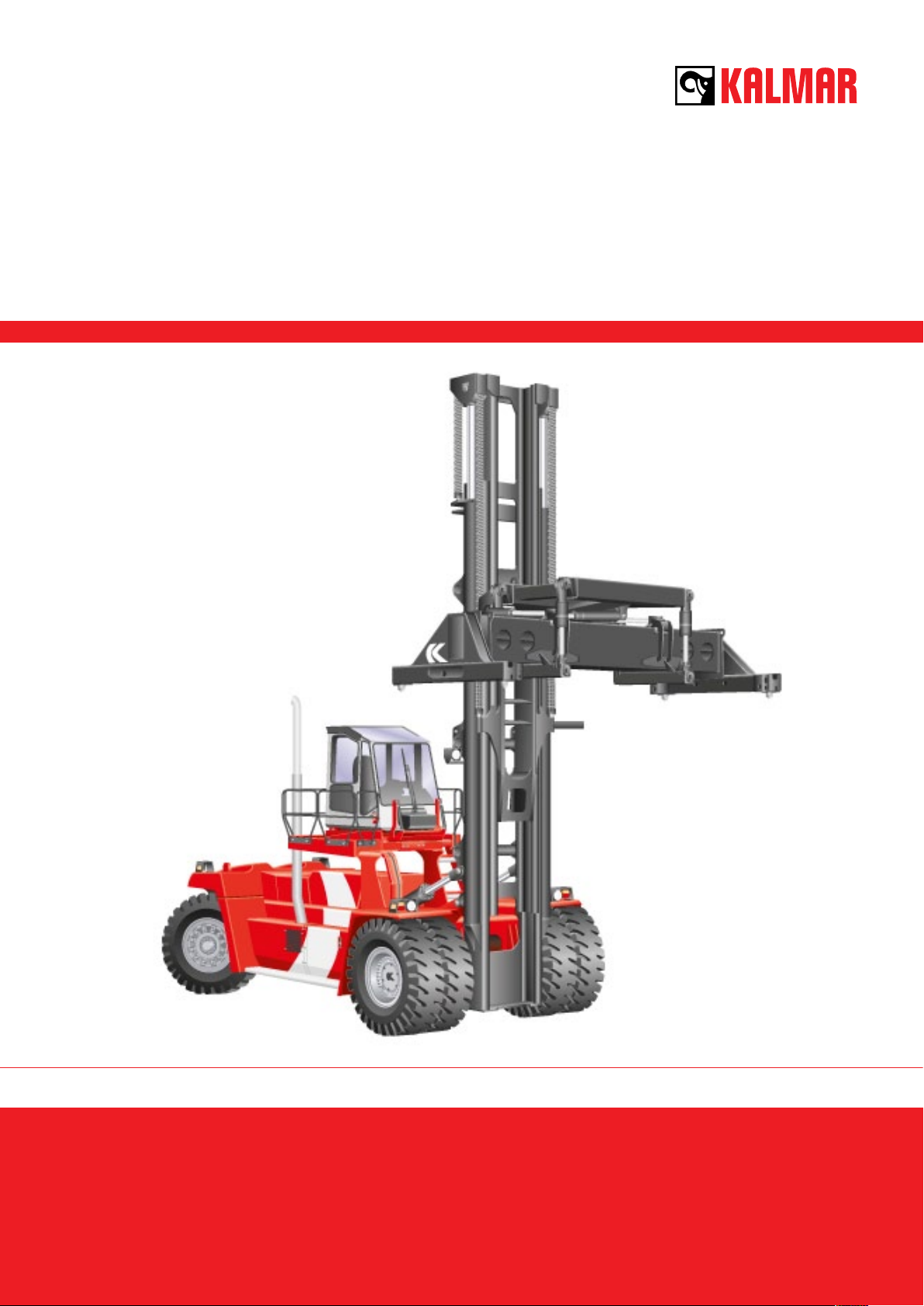
Kalmar DCF360-450CSG
Toplift container handlers
36 – 45 tonnes
Technical information
Introduction
Welcome
Let us introduce to you the details about the
new ultimate top-lift handler – the Kalmar
DCF-series.
These heavy-duty container handlers have
been developed exclusively for ports and terminals with strong demands on productivity
and high quality operation. This is a machine,
which has long been asked for among demanding terminal operators all over the world.
So what about the special benefits?
The Two basic elements
in container handling.
The decision to develop a “brand new” machine came after getting input from terminal
operators for a basic type of machine, but
with superior performance characteristics. We
then decided to build a family of integrated
top-lift handlers that would surpass all existing machines.
Drawing on our global experience we know
that there are two basic elements in container
handling that ensures success in the working
day on every port and terminal. Two elements in the mind of operations, financial and
purchasing managers, but also in the mind of
drivers and maintenance staff.
These two elements were our top priority in
the design and development of the Kalmar
DCF.
Technical solutions are only the tool.
Not the goal.
There is new leveraging technology under the
skin of the DCF in order to provide the best
everyday performance and availability.
PERFORMANCE
PERFORMANCE
ERGONOMICS
ERGONOMICS
DRIVING
DRIVING
LIFTING
LIFTING
CAPACITY AND
CAPACITY AND
DIMENSIONS
DIMENSIONS
We have examined and evaluated every nut,
bolt and component to ensure we provided a
machine with the highest possible specification.
When appropriate simple technical solutions
were available we have applied them, and
when the need was for more sophisticated
systems we have installed them to boost your
uptime and productivity.
AVAILABILITY
AVAILABILITY
RELIABILITY
RELIABILITY
MAINTENANCE
MAINTENANCE
INTELLIGENCE
INTELLIGENCE
SIMPLICITY
SIMPLICITY
The technical optimisation of the Kalmar DCF
means that you will get the best technology
available but still have the feeling of having a reliable, simple, safe and hard working
machine.
Providing the highest possible
throughput.
This is what it’s all about. But of course you
have to add “at the lowest lifetime cost possible”. To reach such a goal you need to focus
on specific critical targets.
2
Ergonomics
A
B
C
D
E
F
G
H
A
B
C
D
E
F
G
H
I
A
A
B
A
B
C
D
A
B
C
D
E
A
B
C
D
E
A
B
C
D
E
F
G
A
B
C
D
E
A
B
C
D
E
F
A
B
C
D
E
F
G
A
B
C
D
E
F
G
H
A
A
B
A
B
C
A
B
C
D
A
B
C
D
E
The heart of top performance in top-lift handling
To obtain the maximum out of your investment, you can never underestimate the
importance of the drivers’ working environment. High throughput demands full driver
concentration and efficiency to keep up the
container moves, but also to avoid injuries
and costly damages.
This is what ergonomics is all about. Being
comfortable and aware.
The driver environment in Kalmar DCF is the
comfortable Spirit Delta high visibility cabin;
appreciated by professional drivers, proven
on thousands of Kalmar container handlers all
over the world.
We focus on four important
ergonomic areas:
• Operation
• Visibility
• Sound and vibrations
• Climate
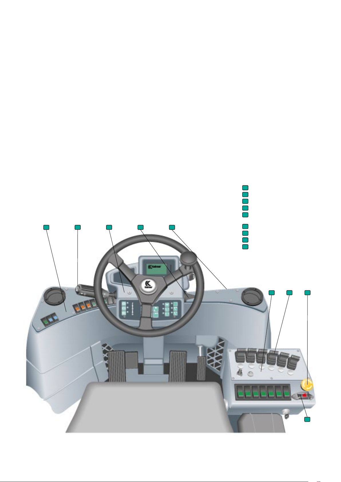
The result is a cabin where everything is optimised to improve driver performance.
Consider this:
• Individually adjustable controls, steering
wheel and seat.
• Intuitively positioned instruments.
• Switches and buttons with lights.
• Comfort pedals.
• Electronic accelerator.
• Central operation/warning display.
• Separately suspended and isolated cabin.
• Shock absorption to minimise vibrations.
• Maximum sound level inside is 70 dB (A).
• Generous interior dimensions and floor
space.
• Optimised visibility – 360˚ all around.
• Electronically controlled heating/
ventilation.
• Filters for fresh air and recirculation.
• High performance air conditioning system,
optional.
• Pollen filter, optional.
Left ins trumen t panel
A
Gear sel ector and m ulti-fun ction lev er
B
Steerin g wheel pan el
C
Direct ion indica tors
Prepare d for termi nal and
dashbo ard atta chment
Hydraul ic control s
F
Panel for h ydraulic fu nctions
Emergen cy switch
Parking b rake
F
G
H
I
3
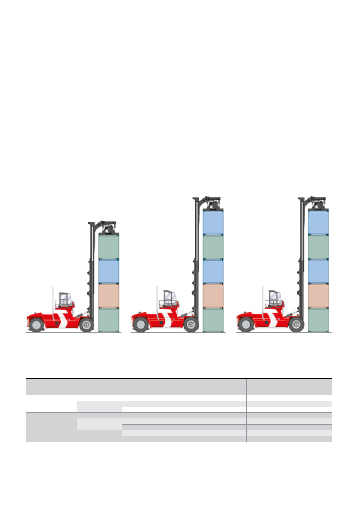
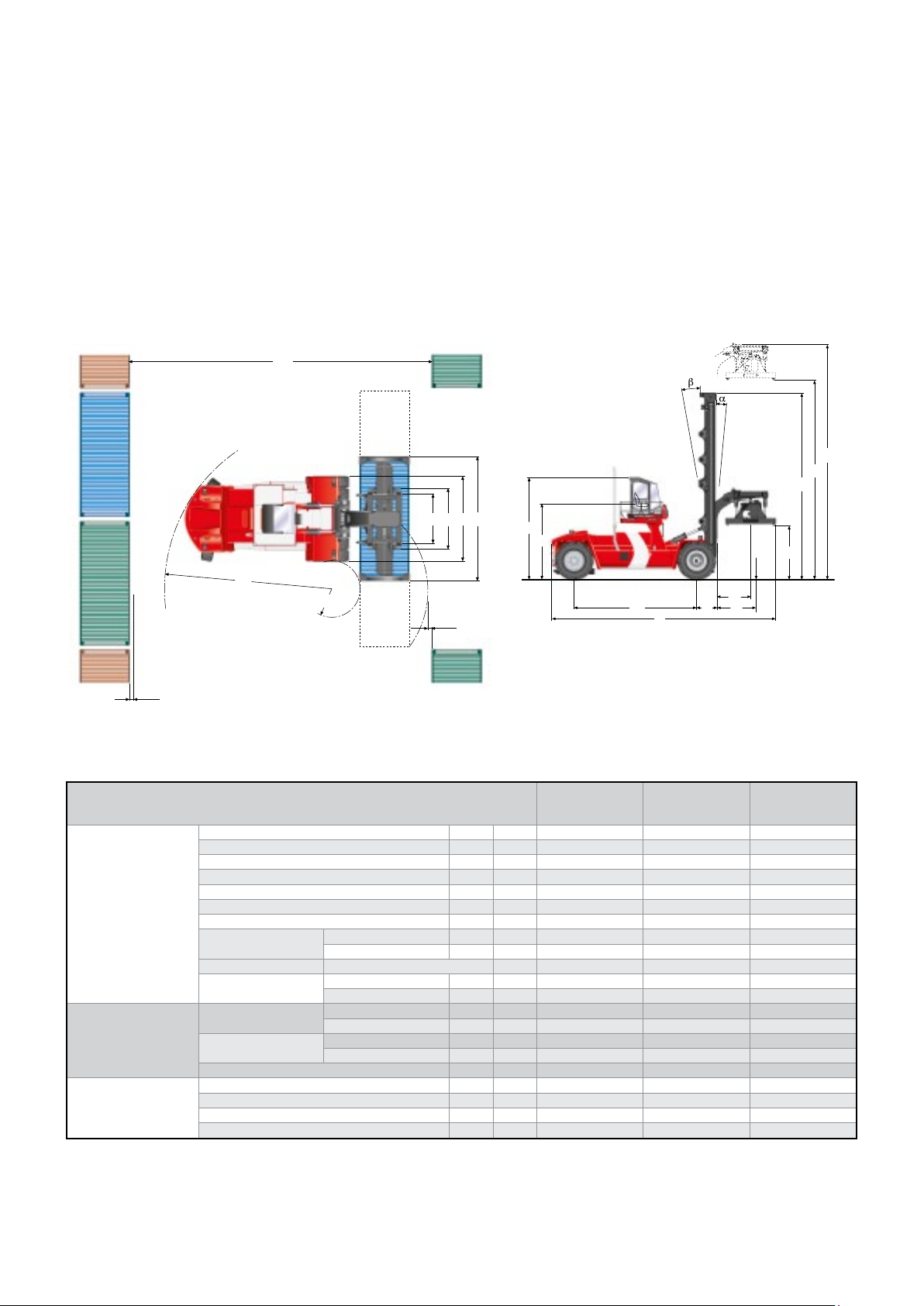
Capacity and dimensions
Matching your handling and throughput needs
When we designed the Kalmar DCF top-lift
we already knew the detailed status of all the
main alternatives on the market. Hence, we
designed a machine which meets or exceeds
the specifications of the others – on the spec
sheet and in reality.
You can choose between three basic models,
each optimised according to lifting capacity
– stability – overall dimensions – weight – toplift speed and driving performance.
Three models cover container handling
between 36 – 45 tonnes capacity, 20’-40’
containers and up to five high stacking at full
capacity. This means that you may easily find
the right machine or combination of machines
to suit your operational requirements.
The design of the chassis, mast, carriage and
spreader has resulted in machines with very
good dimensional-, stability- and operational
characteristics.
41000 kg
In spite of its size and capacity the Kalmar
DCF has a short turning radius. Together with
the optimised visibility and good manoeuvrability it saves terminal space and makes the
machine a smooth operator in confined aisles.
The counterweight and lifting height requirements have been matched with a modern
chassis to keep down the overall weight but
with no sacrifice in stability.
45000 k g
DCF360CSG DCF410CSG DCF450CSG
Capacity and weight
Lifting capacity Classification
Load cen tre attachment retracted
Weight Service weight
Weight front axle unloaded
Weight rear axle unloaded
36000 k g
36000 k g
36000 k g
36000 k g
attachment extended
at rated load
at rated load
41000 kg
41000 kg
41000 kg
41000 kg
DCF360CSG DCF410CSG DCF4 50CSG
kg 3600 0 41000 450 00
L4 mm 1750 1750 1750
L7 mm 1955 1955 1955
kg 6640 0 69750 75000
kg 41300 42290 44000
kg 94800 101450 110500
kg 25100 27460 31000
kg 7600 9300 9500
45000 k g
45000 k g
45000 k g
45000 k g
4
The mast and carriage are computer designed
and optimised (FEM and Catia V5) which allowed for a decrease in the front axle weight.
Together with Kalmar’s integrated high capac-
A1
A2
ity spreader it allows you to fully utilise the
capabilities of mast tilt, slewing, extension,
sideshift at full lifting height and full capacity.
No compromises.
S
B
V1
V
H6
H8
Additionally, we have ensured that every
single detail, component and system have
been selected and manufactured to provide
the highest possible reliability.
H5
H4
H3
H10
R1
100
Dimensions
Truck Truck leng th, with at tachm ent
Standa rd duplex mast
(5 high 8’6, 5 high 9’6)
Attachment Width, min – max
Truck width
Truck height
Seat heig ht
Distance between fron t axle cen ter – front side of mast
Wheelb ase
Track (c-c ), front – rear
Turning radius, outer
Ground cl earance min. unde r truck
Min. track with for 90º
stacking
Height under tw istlocks 4-high – 5 -high ma st
Mast height, min.
Mast tilting, for wards – b ackwards
Hydraulic slewing
Side shif t, ± eithe r side center
Levelling
R2
inner
with 20’ container
with 40’ c ontain er
min.
max
L3
100
DCF360CSG DCF410CSG DCF4 50CSG
L mm 10970 10970 11020
B mm 4450 4450 4450
H6 mm 4650 4720 4720
H8 mm 3560 3630 3630
L2 mm 900 900 950
L3 mm 6000 600 0 600 0
S mm 3020 – 2820 3020 – 2820 3020 – 2820
R1 mm 8 660 8 660 8 660
R2 mm 1090 1090 10 90
mm 280 280 280
A1 mm 11990 11990 11990
A2 mm 14680 14680 14680
H4 mm 12090 15160 15160
H10 mm 2080 2160 2160
H3 mm 7700 9190 9190
H5 mm 15170 17170 17170
α – β º 5 – 10 5 – 10 5 – 10
V mm 12170 – 6070 12170 – 6070 12170 – 6070
º ±3 ±3 ±3
V1 mm 400 400 400
º ±5 ±5 ±5
L
L4
L7L2
5

Lifting performance
1
2
In the palm of your hands
The lifting equipment of Kalmar DCF is an integrated assembly consisting of mast, carriage,
spreader, hydraulics and control system. This
is to ensure you get a reliable and good running machine with high availability even after
long shifts and high load stresses.
A major objective in the development process has been to combine optimum functionality for the driver together with high performance in lifting and load handling.
To leverage operational productivity it’s essential that the driver has full control over every
moment of the handling sequence. This starts
with the 360º visibility from the Spirit Delta
cabin and is followed by the open design of
the mast and gantry. The visual contact with
the stack, container corners, twist-locks and
spreader is optimised.
3
1
Fine-tuning the spreader to handle uneven
levels or loads, mast tilt, extension, twist-lock
landing is accomplished utilising a powerful electronic support feedback and control
system.
Performance
Lifting speed unloade d
at rated load
Lowering speed unloaded
at rated load
Driving speed unloaded forwa rd
reverse
at rated load forwa rd
reverse
Gradea bility at 2 km/h unloaded
at rated load
max, unloaded
Drawbar pull max
DCF360CSG DCF410CSG DCF4 50CSG
m/s 0,42 0,42 0,42
m/s 0,25 0,25 0,25
m/s 0,31 0,31 0,31
m/s 0,36 0,36 0,3 6
km/h 26 26 26
km/h 26 26 26
km/h 23 23 23
km/h 23 23 23
% 38 38 38
% 27 27 27
% 38 38 38
kN 368 368 368
6

1
2
1
1
2
2
Carriage
The integrated gantry with high-strength roller
bearings makes for a secure and durable
setup. The benefits of an integrated gantry are
increased capacity and a decreased loss of
load centre. The gantry is a completely new
design, made of solid steel instead of welded
beams, which improves reliability and see
through visibility.
1
Mast
The Kalmar DCF has as standard a duplex free
visibility mast, made of high strength steel to
provide a long life with minimal deflection at
high lifting heights. Maximum lifting height is
15160 mm or five containers high under the
twist-locks. The mast is equipped with the
new Kalmar high speed lifting system, which
provides very fast handling of loads up to 22
tonnes.
The mast is made for high reliability and simple maintenance. It requires only two hoses
and one cable passing over the mast roller to
feed the hydraulic and electrical functions of
the spreader.
Levelling 5˚Sideshif t ±40 0 mm
Key functions:
• Levelling – corrects the inclination of the
spreader to uneven containers.
• Slewing – compensates when the machine
is not positioned 90º to stack.
• Side-shift – compensates when the
machine is positioned right or left of the
container.
• Extend/Retract – extends the capability
when loading/unloading trucks or rail cars.
3
Spreader
The integrated spreader is suspended from
four (4) hydraulic cylinders, which compensate for unevenly loaded or stacked containers. Powered pile slope is optional. The
spreader is easily adjustable with the touch of
a button for 20’ or 40’ containers and can be
side-shifted 400 mm either side of centre. Two
additional hydraulic cylinders provide precise
control of the slewing function.
Slewing ± 3˚.
The mechanical and electrical safety inter-lock
systems prevent locking or releasing the
twist-locks if the spreader is not properly positioned on the container. It also prevents lifting
of the spreader when the twist-locks are not
fully engaged or fully released.
Extend /retract, 200 mm
The lowering interrupt system prevents chain
slack once it is landed on the container. Lights
on the instrument panel and spreader indicate proper use of the spreader and locked/
unlocked twist-locks.
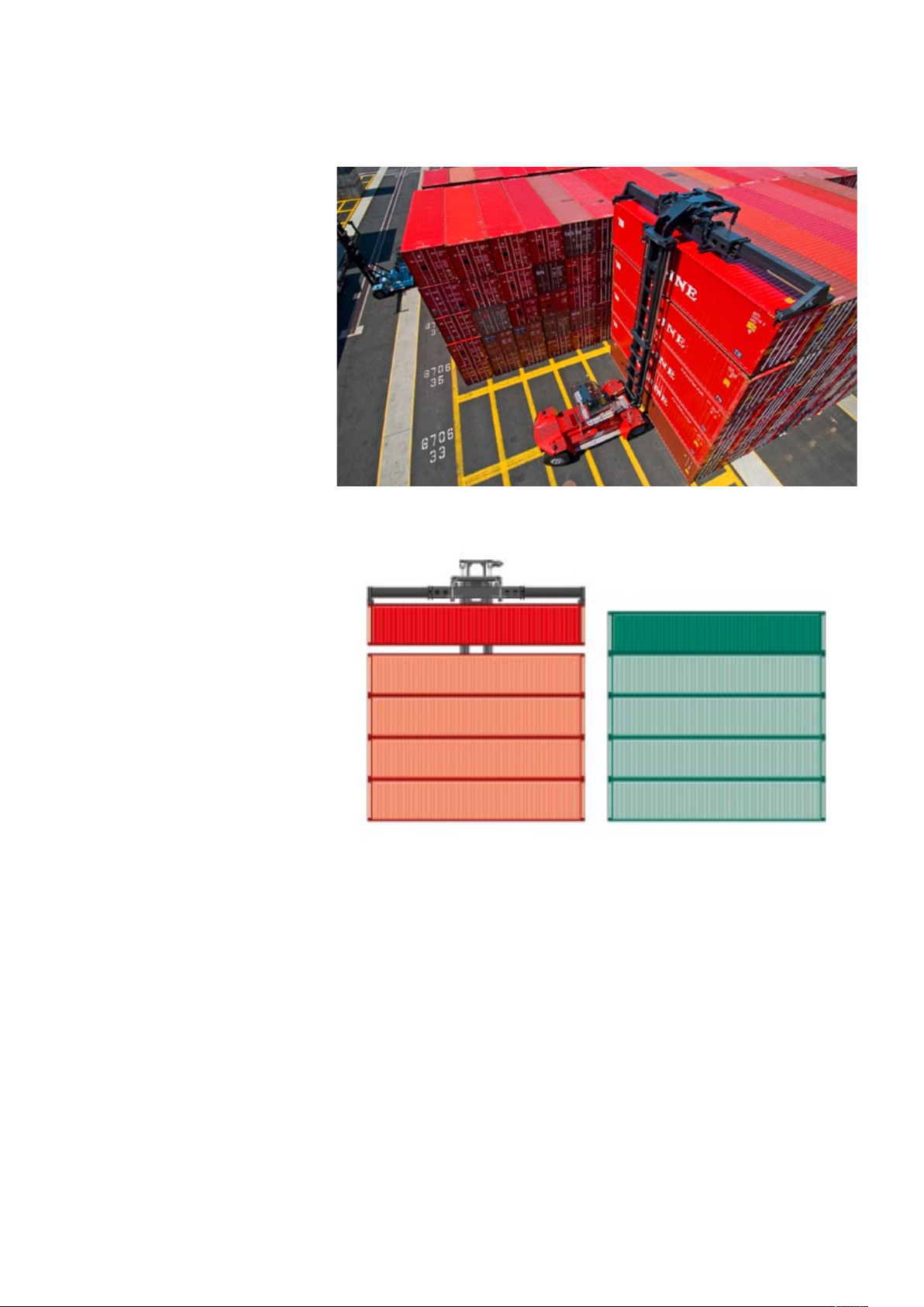
The Kalmar spreader will handle all ISO standard containers ranging from 20’ to 53’ long
and 8’ wide to 8’6” wide. All containers must
have the standard ISO 20’ or 40’ footprint.
7

Driving performance
1
1
2
1
2
3
1
2
3
4
1
2
3
4
5
1
2
3
The basic set up is a key factor for high productivity
Optimised ergonomics. Perfect matching of
capacity. Efficient lifting.
The forth key factor for high top-lift productivity is the basic machine set up. Heavy loads
and high lifting speed, for example, put critical
demands on the engine and hydraulic power
support. Fast positioning during the stacking cycle requires precise control with tight
turning radius, effective and reliable brakes
and high engine torque. Fast transportation
requires good stability, reliable brakes and
smooth transmission.
Of course, all the working components and
systems have to cope with the most demanding stresses during long shifts and heavy
operations everyday.
We have put highest priority on overall technical reliability. Looking at the choice of each
component, long running cycle times and
how it all comes together. We have incorporated into the DCF several major components
and systems from our extremely reliable
DRF reachstacker. More than 1000 of these
machines have been delivered in the past few
years and have proven the durability of the
components and systems, and its low running
costs.
2
Engine
The Cummins and Volvo engines provide
power for driving and the working hydraulics.
The engines are low-emission turbo diesels
with fuel injectors and intercoolers. The design of the combustion chambers, along with
the precise fuel injection control, ensures
more efficient combustion to provide lower
emissions with increased torque and power.
The engines meet the Tier 3 requirements,
and the sound and vibration standards.
The radiator is a 3 chamber design with a single fan to provide cooling for the engine and
transmission. The engine cooler’s separate
expansion chambers are fitted with a level
sensor that indicates low coolant level.
3
Transmission
The transmission transfers power from the
engine to the hydraulic pumps and drive line.
The engine and gearbox control systems
work together to find the optimum balance
between power and fuel economy at any
given time. The transmission system consists
of a torque converter and a gearbox. The
gearbox is automatic, but can partly be
shifted manually.
5
Steering system
The steering axle is built from a single piece
of high strength steel, which means as fewer
parts requiring less maintenance and higher
structural integrity. The suspension points on
the steering axle utilise a maintenance-free
plastic. The hydraulics that feed oil to the
steering cylinder is optimised for enhanced
driving feel. The orbitrol and the priority valve
jointly provide gentle yet precise steering
movements.
6
Brakes
The brake circuit is separated from the
hydraulic system and has its own tank,
cooler and high-pressure filter. A temperature
transmitter in the brake oil tank regulates
the cooling fan. The foot-brake valve, which
controls the oil feed to the brakes, is sensitive
enough so that the driver can brake optimally
yet gently. The parking brake is activated
automatically when the ignition is turned off.
4
Drive line
1
Chassis
The frame forms the basis of the machine’s
lifting and manoeuvring characteristics and
was designed exclusively for a top-lift operation. The beam construction, along with its
width, makes the DCF stable, torsion resistant
and service-friendly.
The propeller shaft and drive
axle transfer the power
from the transmission
to the driving wheels.
The mountings on the
propeller shaft are fitted
with cross-flanges for op-
timum strength. The drive axle
The frame is 3D modulated (Catia V5) and
designed (FEM) in order to eliminate critical tensions under various kinds of strain.
The mechanically welded chassis has been
gears down in two stages, differential
and hub reduction. The engine provides
maximum torque at the drive wheels, which
spares the transmission.
optimised according to strength, weight and
stability.
4
8

Wheels and tyres
1
2
3
4
5
1
2
1
1
2
3
4
Tires are an important cost factor to consider
when improving operational performance.
Therefore the Kalmar DCF410 and 450 are
fitted with 18.00×33 tires, all models use
identical sizes on both drive and steer wheels.
This improves the machine stability, comfort
and reliability and requires only one single
spare tire. The larger dimension tires should
decrease the tire wear and tear and improve
the tire life.
2
5
1
3
6
Drive train
Engine Man ufactur er – type d esignat ion Cu mmins QSM11 Tier 3 Volv o TAD1250VE Tier 3
Transmissi on Manufacturer – t ype desi gnation
Driving axle Type Hub reduction Hub reduction
Fuel – typ e of engine Diesel – 4 s troke Diesel – 4 s troke
Displac ement
Rating IS O 3046
Peak torq ue ISO 304 6
Number o f cylinde rs – compre ssion
Fuel consu mption, n ormal driv ing
Alternator typ e – power
Start b atter y, voltage – ca pacity
Clutch, t ype Torque conve rter Torque conve rter
Gearbox , type Powersh ift Powershif t
Number s of gears, f orward – reverse
cm³ 10 80 1213
kW – rpm 261 – 2000 260 – 160 0
Nm – rpm 1830 – 1100 -1400 1760 – 1400
cm³ 6 – 18,1:1 6 – 16,3:1
l/h 18-22 18-22
W AC – 2400 AC – 2400
V – Ah 2×12 – 140 2×12 – 140
Standar d O ption
Dana 15.7 TE320 00 Dana 15.7 TE32000
4 – 4 4 – 4
9

Intelligence
The simple way to put bits and pieces together
All vehicles today – cars, highway trucks,
wheel-loaders, cranes etc – are constructed
with more and more sophisticated components and systems. Each part interacts closely
with the others and to reach the full potential
requires computer assistance.
This built-in intelligence is designed to support
and leverage your container operations, not
confuse it.
The Kalmar DCF posses a well proven, thoroughly tested and optimised control system,
which supports your driver, mechanics and
financial controller. And it is simple to use.
It is designed to get the most out of the
machine during the top-lift operations, to
improve safety, to avoid unnecessary damage
on components, to advise of scheduled preventive maintenance, to get machine statistics
and so on.
KID
KIT
KCU
KDU
The reliable distributed control system.
Two things are needed for a command initiated by the driver to result in a particular
function, or for several functions to work
together: power-feed and communication.
The power-feed supplies the machine’s
electrical or electro-hydraulic functions with
voltage. The communication system controls
and checks that the functions have been
activated, waits in standby mode or indicates
faults.
EDC
TCU
The communication network layout.
Both the power-feed and communication
system form an integrated network distributed to the critical areas of the machine. The
main components of the network are the
control units (nodes). Each node has its own
processor and integrates with each other. All
communication, control signals and signal
information are sent via data buses. All nodes
in the network are talking and listening to
each other.
KDU
KDU
Kalmar Cabin Unit
Kalmar In formation Terminal
Kalmar In formation Display
Electronic Diesel Contro l
Transmission Control Unit
Kalmar Di stributed Unit
The data transfer is secured by a CAN-bus
(two-wire) technology, which means high reliability and extremely low risk for disruption.
CAN-bus loops have been used in the Kalmar
machines since 1995.
The power-feed for the functions are supplied
separately via distribution boxes located in
the cabin. The power is distributed and guided
by instructions generated from the communication network.
10

Control functions – support the driver.
The driver and machine communicate very
simple via the Kalmar Information Terminal
and the Information Display located right in
front of the driver in the cabin. The two-way
communication – from the driver to the machine and opposite – is handled by the KCU
(Kalmar Cabin Unit) which is the control node
for the entire network.
Information to the driver comprises alarm
warnings, operating details and action-guided
information. Messages, status, fault indications etc are presented on the Information
Display, while warnings and other monitoring
indications are presented to the left.
Messages are only presented when they are
relevant to the driver and the operation, so
the driver can focus on the job instead of
checking meters and indicators.
Heating /Ventilation
and Air con ditioning.
Service information.
Engine revs, travelling speed,
time and fuel.
Batter y status.
Engine
Temperature
and pressure.
Transmissio n
Temperature
and pressure.
11

Availability
We have made sure your
investment becomes profitable
To understand the full potential of your investment requires being aware of the details,
features and technical matters in a machine
like the Kalmar DCF.
But when it comes to availability it is critical
that it operates constantly and is kept in good
condition with an absolute minimum of maintenance and repairs.
Less stops and no stops.
The Kalmar DCF is designed for long shifts,
which means that you may have to replace
the driver before you have to call it in for fuel.
The good weight/engine power relationship
combined with a fuel tank designed for 50
hours of operation make these machines run
the extra hours you want them to.
The service intervals have been extended to
500 hours, which means that you don’t have
to take the machine out of work more than 6
times a year (3000 hours utilisation).
The DCF is designed for fast daily inspection
and preventive maintenance. All checkpoints
are easy accessible and concentrated to specific locations. Lubrication free components or
central lubrication points have been utilised.
The wet disc brake system is practically maintenance free.
The indicator and monitoring support built
into our control system make sure that the
machine won’t be misused or maintained
incorrectly. The driver and mechanics will
always get indications and guidance in time to
avoid unnecessary and costly wear and tear
or technical breakdowns. No unwanted stops.
Reliability starts already
at the concept stage.
One of the guiding principles in designing the
DCF was to minimise the number of potential
sources of error. Therefore the machines consist of as few components and moving parts
as possible. The functionality and operational
reliability is assured by extensive testing.
Fewer comp onents
makes for increased
reliability, only two hoses
and one harness runs
over the mast wheel.
12

1
1
2
3
1
2
1
2
3
4
1
1
2
1
2
3
4
1
2
3
4
The reliable and maintenance
friendly hydraulic system.
3
5
1
2
The hydraulic system is critical.
No other part of the machine is working so
hard under continuous pressure. To secure
the reliability we have minimised the number
of hydraulic components and couplings.
The main valve has an integrated servo which
helps increase precision and control over the
oil flow. The hydraulic oil is fed to the carriage
Other improving features:
1
Large dimensions of hydraulic hoses
improves the hose´s lifetime (slower flow,
less friction and less heating).
2
Thermostatic cooling of both the main
system and the brake system improves
the oil lifetime (temperature control,
optimised working temperature).
3
High density filter improves the oil lifetime
(clean oil).
4
ORFS – leak proof couplings all around
improves reliability (minimises leakage).
5
All main hydraulic components at ground
level are gathered on a separate plate,
bolted to the chassis and therefore simple
to remove.
and spreader by a variable piston pump,
which saves a lot of power and energy compared to continuous oil circulation. Another
innovative solution – the valve for the gantry
and spreader functions has been mounted on
the gantry. The result is an instant and accurate connection between lever and function.
This also minimises the number of hydraulic
A safe communication network
The control and monitoring system is the
new Kalmar control system, but already successfully applied in more than 1000 Kalmar
machines worldwide.
components in the chassis.
This new reduntant CAN-bus system is proven
In order to maintain optimum functionality
in the system even under extreme operating conditions, cleaning and cooling of the
hydraulic oil is highly efficient. The hydraulic
brake circuit is separated from the main system and is fitted with its own filters.
to be excellent in functionality and reliability.
The network of control nodes allows for less
wiring and connectors which reduces the
number of sources of error. The power-feed
for each node and the transfer of control
signals are independent of the other nodes,
which means the risk of disruption becomes
minimal. The redundant design means that
there are always two paths to choose to
maintain communication, which results in
extra safety and reliability.
13

Notes
14

15

Global presence and local service bring
our products and solutions closer to our customer.
Cargotec improves the efficiency of cargo flows on land and at sea – wherever cargo is on the move.
Cargotec’s daughter brands Hiab, Kalmar and MacGregor are recognised leaders in cargo and load handling
solutions around the world. Cargotec’s global network is positioned close to customers and offers extensive
services that ensure the continuous, reliable and sustainable performance of equipment.
Cargotec’s class B shares are quoted on the NASDAQ OMX Helsinki. www.cargotec.com
Cargotec Sweden AB
Torggatan 3
SE-340 10, Lidhult, Sweden
tel. +46 372 260 00
fax +46 372 263 90
www.cargotec.com
TI-LC 45-EN-WW / 2010.02.15
 Loading...