


Kalmar DCD90, DCD180 Service Manual

00
General
Technical
Handbook
DCD90-180
DCD70-32E3 - 70-40E5
This Handbook deals with the design
and maintenance of Kalmar forklift
trucks, type DCD.
10
20
30
40
Chassis and cab
Electrical system
Engine
Transmission,
drive axle, brakes
In addition, it gives details of
troubleshooting and the most common
corrective maintenance.
Operation and other matters that are
primarily of interest to the operator are
included in the Instruction Manual.
Kalmar Industries AB
We reserve the right to modify
our design and material specifications without prior notice.
50
60
70
80
Steered axle
Hydraulic system
Lifting mast and
fork carriage
Publ. No. 920 937 – 9350 02-08
AdEra Dokument AB, Växjö 2002
90
Periodic supervision


DCD90-180
Technical Handbook
9350
00-11
Contents
P.Group 00
1
Group 00
Contents
Safety regulations ..................................................................... 2
General ..................................................................................... 5
Applications ......................................................................... 5
Design ................................................................................. 6
Component units ................................................................. 6
Main components ................................................................ 8
Supplementary books .......................................................... 9
Replacement system – Spare parts .................................... 9
Tools .................................................................................... 9
Tightening torques ............................................................. 10
System of units .................................................................. 12
DCD90-180
Technical Handbook
Safety regulations
It is important that you read the instruction manual
Incorrect handling can lead to personal injury or damage to products and/or property. Therefore, read the instruction book very
carefully before operating the truck. The instruction manual contains important information about your Kalmar truck, about the
operation of the truck, about safety during operation and about
the truck’s daily maintenance. In addition, you will find useful information that will make operations easier for you in your daily
work.
Ask your foreman/group leader if there is anything in the manual
that you do not understand or if you feel that information is missing in any area.
The symbol is used on our products in certain cases and
then refers to important information contained in the instruction
manual. Make sure that warning and information symbols are always clearly visible and legible. Replace symbols that have been
damaged or painted over.
9350
00-11
P.Group 00
2
Safety regulations
In this handbook warnings are inserted that apply to your own
safety. Warnings point out the risk of accident that can cause personal injury.
WARNING!
Warns of the risk of serious personal injury, possible
death and/or serious damage to product or property if the
regulations are not followed.
For technical warnings, that point out the risk of break down, the
word IMPORTANT is used:
IMPORTANT!
Is used to draw attention to such occurrences that can
cause damage to the product or property.
For information that facilitates the working process or handling,
N.B. is used:
N.B. Draws attention to useful information that helps the
working process.

DCD90-180
Technical Handbook
Safety regulations
Safety regulations aimed at reducing the risk of personal
injury and damage to loads or other property.
9350
00-11
P.Group 00
3
Intended of use
z The truck may only be used for the purpose for
which it was intended, namely, to lift and transport
goods, the weight of which does not exceed the
maximum permitted load capacity of the truck.
z The truck may not, without specific permission
from Kalmar, be modified or re-built so that its
function or performance is altered.
z The truck may not be driven on public highways if
it has not been adapted to comply with national
road safety regulations.
Operator requirements
z The truck may only be driven by operators who
have been specially trained and who have the
company’s authority to do so.
z Laws and other regulations relating to driving li-
cence, operator ID, log book, etc., must be followed at all times.
z The operator must be aware of and follow all local
safety regulations.
Operation of the truck is prohibited:
z If any of the fitted safety equipment, such as rear
view mirrors, headlights, reversing alarm (optional) does not function correctly.
z If there is a fault with the brakes, steering or lift
equipment.
z If the truck is fitted with tyres not approved by
Kalmar.
Operating regulations
z Before starting, always check to ensure that no-
body is in the way of the truck or its equipment.
z Make sure that nobody walks or stands under-
neath raised forks or other equipment, whether
they are loaded or not.
z The operator must always face the direction of op-
eration and take particular care in areas where
persons or other vehicles are likely to appear in
the vicinity. If visibility is limited by the load, the operator should operate the truck in reverse.
z It is prohibited to transport passengers on the
truck outside the cab or on the load. Passengers
may be transported inside the cab only on condition that it is equipped with a fixed passenger
seat.
z It is prohibited to lift people if the truck is not
equipped with an approved lift cage.
z It is prohibited to exceed the load capacity of the
truck. See capacity plate and loading diagram.
z It is prohibited to transport loads in the raised po-
sition as this entails a risk of the truck tipping. All
transportation shall take place with the load in the
lowered position and with the mast tilted backwards to the maximum.
z The operator must adapt the speed of the truck to
the character of the load, conditions of visibility,
the character of the roadway/surface, etc.
z The operator shall avoid powerful acceleration
and braking when turning. In addition, the operator shall always moderate the speed of the truck
when turning so as to avoid the risk of lateral skidding or tipping.
z The operator shall take particular care when oper-
ating in the vicinity of electrical power lines, viaducts, quay-sides, ramps, gates/doors etc.
z Safety belts must always be worn, if fitted. In the
event of the truck tipping, always remain in the
cab and grip the steering wheel securely. Never
try to jump out of the cab.
z The parking brake can also be used as an EMER-
GENCY BRAKE. However, having been used for
emergency braking, the brake linings must be inspected and replaced if needed. If the parking
brake has been mechanically released, it must
always be reset in order for the truck to regain
the parking brake function.
Interrupted operation, parking
z Always check that the gear lever is in the neutral
position before turning the ignition key to restart or
to reset an emergency stop.
z Never leave the operator’s cab without applying
the parking brake (ON position).
z Always remove the ignition key if the truck is to be
left unattended.
Other important points to remember
z The truck’s hydraulic system includes high pres-
sure hydraulic accumulators. Always be extremely careful when working with the hydraulic system
and avoid being unnecessarily close to the hydraulic equipment, lines and hoses. Before working on the hydraulic system, the accumulators
must be emptied into the tank, with the help of the
special accumulator evacuation valve.
z Handle batteries and junction boxes with great
care. The batteries must always be protected over
the poles and connections.
z Always rectify any damage or wear and tear that
can risk personal safety or that can affect the
functions of the truck or its service life.
z Trucks with tippable cabs: The cab must always
be tipped over the point of balance. If there is insufficient lateral space the cab must always be secured against accidental lowering with a brace or
similar.
z Avoid touching oils and greases. Avoid inhaling
exhaust and oil fumes.
z Welding painted steel produces poisonous gas-
ses. Paint should therefore be stripped before
welding, good ventilation ensured and/or face
mask with filter used.
Operating with attachments
zThe operator must always take the effect of the wind
into account when handling containers. Avoid lifting
with a wind strength in excess of 12 m/s (27 mph/40
feet per second).
zAlways drive carefully so as to avoid attachments
colliding with pillars, cables, etc.
zCarefully study the "Lift methods" section of the
instruction manual.

DCD90-180
Technical Handbook
Safety regulations
Safety instructions for working with tyres
9350
00-11
P.Group 00
4
z Tyre changing can be dangerous and should only
be carried out by specially trained personnel using
proper tools and procedures.
Failure to comply with these procedures may result in faulty positioning of the tyre and/or rim and
cause the assembly to burst with explosive force
sufficient to cause physical injury or death. Never
fit or use damaged tyres or rims.
z Never attempt to weld on an inflated tyre/rim
assembly.
z Never let anyone assemble or disassemble tyres
without proper training.
z Never run the truck on one tyre of a dual assembly.
The load capacuty of a single tyre is then dangerous-ly exceeded and operation in this manner may
damage the rim.
z Deflation and dismantling
– Always block the tyre and wheel on the opposite
side of the vehicle before you place the jack in
position. Always crib up the blocks to prevent
the jack from slipping.
– Always check the tyre/rim assembly for proper
component seating prior to removal from the
truck.
– Always deflate the tyre by removing the valve
core prior to removing the complete assembly
from the truck or dismantling any of the component. Before loosening mounting bolts, run a
wire through the valve stem to ensure that it is
not blocked. Ice or dirt can prevent all the air
from escaping. Deflate and remove valve cores
from both tyres of a dual assembly.
– Never position body in front of the rim during de-
flation.
– Always follow assembly and dismantling proce-
dures outlined in the manufacturer’s instruction
manual, or other reconized industry instruction
manuals. Use proper rubber lubricant.
– Never use a steel hammer to assembling or dis-
mantling rim components – use a lead, brass or
plastic type mallets. The correct tools are available through rim/wheel distributors.
– remove bead seat band slowly to prevent acci-
dents. support the band with your thigh and roll
it slowly to the ground in order to protect back
and toes.
– Disassembly tools apply pressure to rim flanges
to unseat tyre beads. Keep your fingers clear.
Slant disassembly tool about 10 degrees to
keep it firmly in place. Always stand to one side
when applyin g hydraulic pressure. Should the
tool slip off, it may cause fatal injury .
z Rim inspection
– Check rim components periodically for fatigue
cracks. Replace all cracked, badly worn,
damaged and severely rusted components.
– Always select the correct tyre size and construc-
tion matching the manufacturer’s rim or wheel
rating and size.
– Do not use over-size tyres, too large for the
rims, e.g. 14.5 inch tyres with 14 inch rims or
16.5 inch tyres with 16 inch rims.
– Never use damaged, worn or corroded rims/
wheels or fitting hardware. Always verify that the
rim is in a serviceable conditioning.
– Always clean and repaint lightly rusted rims.
– Never use a rim/wheel component that can not
be identified. Check rim parts against multipiece rim/wheel matching charts.
z Assembly and inflation
– It is important that the inflation equipment is
equipped with a water separator to remove
moist-ure from the air line in order to prevent coorosion. Check the separator periodically to ensure that it is working properly.
– Make sure that the lockring is in its right posi-
tion.
– Never mix different manufacurer’s parts since
this is potentially dangerous. Always check
manufacturer for approval.
– Never seat rings with hammering while the tyre
is inflated. Do not hammer on an inflated or partially inflated tyre/rim assembly.
– Always double check to ensure that the rim as-
semblies have been correctly assembled and
that securing studs and nuts are tightened to the
correct torque setting.
– Never inflate tyres before all side and lockrings
are in place. Check components for proper
assembly after pumping to approximately 5 psi
(=34 kPa, =0.34 bar)
– When adding air to a tyre on an industrial truck,
use a clip-on chuck and stay out of the danger
area. If the tyres has been run flat then the rim
must be dismantled and all parts inspected for
damage.
– Under-inflated tyres have a serious effect on the
stability of the truck and reduces the safe load
handling capacity. Always maintain tyres at the
correct inflation pressures. Check inflation
pressure daily. Do not over-inflate.
– Inspect tyres regulary – every day if possible.
Look for and remove broken glass, torn pieces
of tread, embedded metal chips etc. Inspect for
uneven or rapid tread wear, usually caused by
mechanical irregularities, such as brakes out of
adjustment or excessive toe-in and toe-out. If
discovered, correct the irregularity immediately.
z When installing and tightening trail wheel bolts, ob-
serve the following:
– Ensure that trail wheel or hub mounting surfac-
es and trail wheel fastener mounting surfaces
are clean and free from paint and grease.
– Tighten bolts to specified torque settings. use
staggered sequence; i.e. top bolt, bottom bolt
etc.
DCD90-180
Technical Handbook
General
9350
00-11
P.Group 00
5
Applications
The Kalmar DCD90-180 range of trucks is based on an entirely
new approach to the design and production of medium-heavy,
diesel-powered forklift trucks. The trucks are durable and safe
and their accessibility for service and maintenance is unexcelled.
Due the their versatility, the trucks can be used in a number of applications, such as:
z Steelworks and heavy engineering industry, where the
trucks handle individual tasks in the handling of mediumheavy goods.
z The forest industry for handling logs by means of a log grap-
ple attachment, sorting of logs at sawmills and handling of
sawn timber in units loads.
z Ports and container terminals for handling medium-heavy
goods and handling empty containers.
z Factories producing houses – lifting of house sections.
KL734
DCD90-180

DCD90-180
Technical Handbook
General
9350
00-11
P.Group 00
6
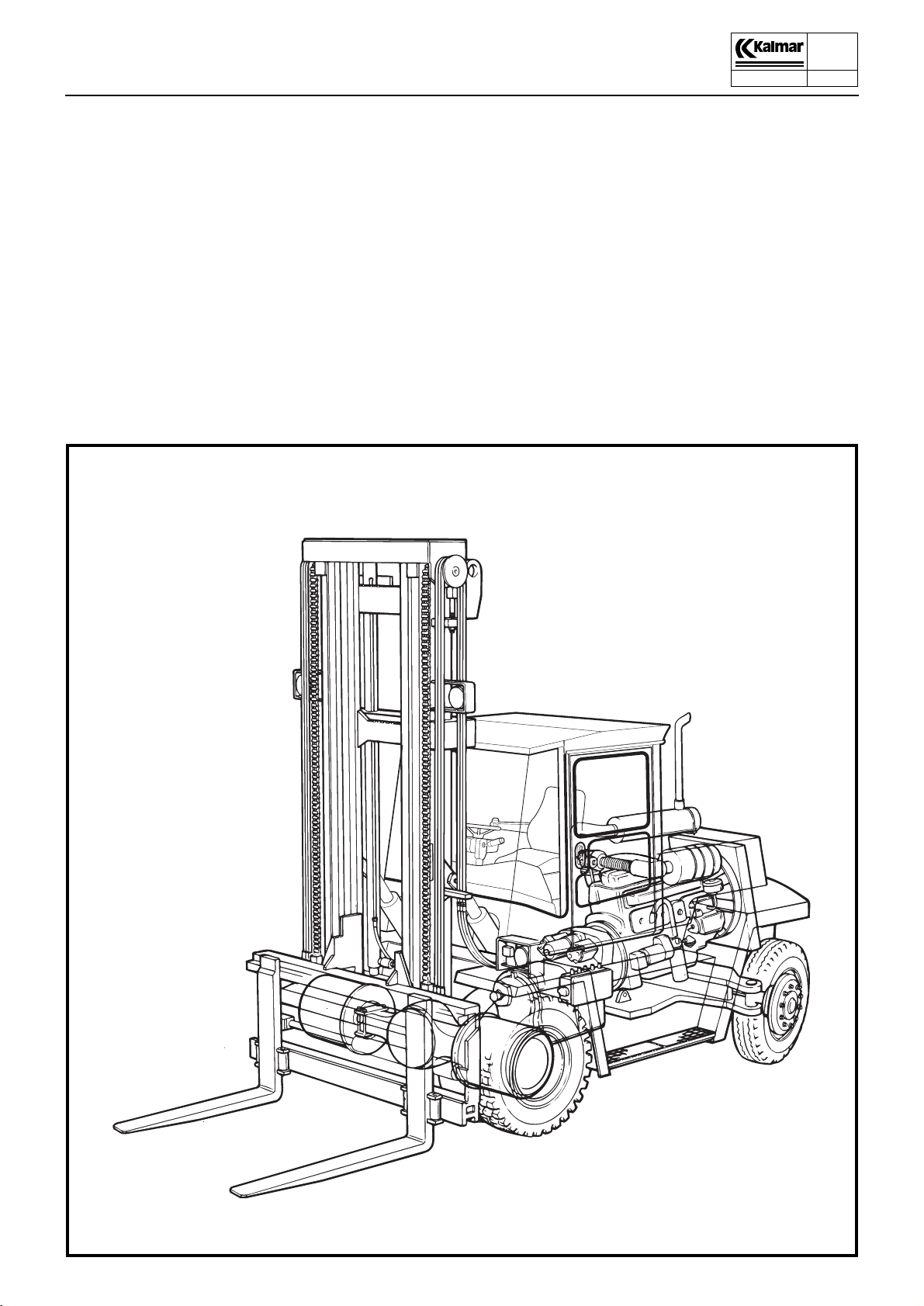
Design – general survey
Kalmar DCD90-180 diesel trucks are of sturdy design for heavy
duty. They are built around a chassis which has high strength and
torsional stiffness and an extremely low centre of gravity.
The operator’s cab is provided with vibration isolation and sound
insulation and offers excellent all-round visibility.
The operator is provided with many facilities for adjusting his
seating attitude. The seat, backrest and springing of the operator’s seat can be adjusted in a wide variety of ways.
The cab is tiltable and offers excellent accessibility to the transmission and pumps. The engine is easily accessible through a
casing, divided in two halves.
The Volvo or Perkins six-cylinder turbocharged engine TD640VE
or TD730VE/TWD731VE, combined with a three-speed gearbox
with torque converter, provides smooth power whenever needed.
The drive axle with hub reductions, the oil-cooled hydraulic brake
system and the pendulum-mounted steered axle with double-acting steering cylinder satisfy very strict demands on strength and
mobility when travelling on irregular surfaces.
The hydraulic system is reliable and has high performance
charged by two or three hydraulic pumps.
For further details, see group 70.
Component units
z Sound-insulated and safety-tested operator’s cab with ex-
cellent all-round visibility. The non-slip, substantial steps provide convenient access to the cab. All models in the series
can be equipped with a rotatable operator’s seat.
z Clearly arranged instrument panel.
z Engine – Volvo TD640VE or TD730VE/TWD731VE six-cyl-
inder, four-stroke, turbocharged diesel engine with direct injection and thermostatically controlled water cooling.
The engine is equipped with:
– Injection pump with centrifugal governor that compensate
for load variations.
– Alternator.
– For alternatives, see separate table.

DCD90-180
Technical Handbook
General
z Gearbox with torque converter
9350
00-11
P.Group 00
7
– Constant-mesh gearbox in which hydraulically actuated
clutches for the different gears. The clutches are electrically operated.
– Torque converter, which is a hydraulic coupling that ampli-
fies the output torque on an increase in load. Torque conversion takes place smoothly and steplessly throughout
the engine speed range.
– Oil cooler connected to the engine cooling system for
cooling the oil in the gearbox and torque converter.
– Oil pump which supplies oil under pressure to the gearbox
and torque converter.
– Full-flow oil filter for effective cleaning of the gearbox oil.
z Drive axle with two-stage reduction - in the differential and
the hub reductions.
– Oil cooled hydraulic brakes for the foot brake, e.g. Wet
disc brakes.
– Disc type parking brake applied by a sturdy spring and
released by hydraulic oil pressure.
z Hydraulic system with
– Gear type hydraulic pumps connected to take-offs on the
torque converter. One pump for working hydraulics and
one for steering and accumulator charging, which in turn
serves the brake circuits.
– Main valve for controlling the main hydraulics. The valve
is controlled hydraulically from the cab. An electro-hydraulic servo system is available as an option.
– A high pressure filter after each pump for effective clean-
ing of the hydraulic fluid before it is fed to the system.
– Steering valve (Orbitrol) - flow-control valve which sup-
plies hydraulic fluid to the steering cylinder.
z Steered axle with pendulum mounting and double-acting
steering cylinder.
z Sturdy clear-vision mast. Of duplex or triplex design, with or
without free lift.
– Outer mast with hydraulically controlled 5° forward and
10° backward tilting.
– Tilting cylinders with back-pressure valves to prevent the
load from tilting the mast forward.
– Inner mast with support rollers that carry the forces on the
mast. Yoke with guide rollers for the hydraulic hoses and
guide sprockets for the lifting chains.
– Lifting cylinders - two cylinders mounted on the outer
mast.
z Fork carriage designed for optimum visibility and equipped
hydraulic with fork positioning and sideshifting (optional).
DCD90-180
Technical Handbook
General
9350
00-11
P.Group 00
8
1
23
7
KL734
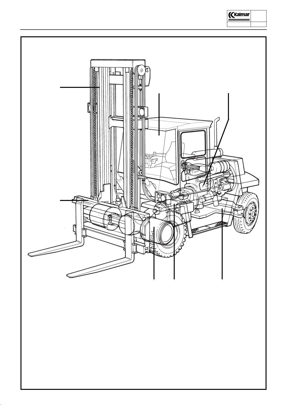
1. Free -visibility mast, with two lifting cylinders
2. Operator’s cab, rubber suspended cab
3. Engine, six-cylinder diesel engine with
turbo-compressor
4. Steering axle, with pendulum suspension and
double acting steering cylinder
65 4
5. Gearbox, combined with torque converter
6. Drive axle, with hub gearing and oil-cooled
hydraulic brake
7. Fork carriage, hydraulically controlled fork
positioning and sideshift
Main component units

DCD90-180
Technical Handbook
General
9350
00-11
P.Group 00
9
Main components
Alternative drive lines
● = Standard ❍ = Optional
Engine *Turbo **Turbo, intercooler
Volvo TD640VE* 129 kW/690 Nm ●●●●●●●●●●●
Perkins 1006-60T1* 85 kW/465 Nm ❍❍❍❍❍
Volvo TD730VE* 150 kW/800 Nm ❍❍❍❍❍❍❍❍❍❍
Volvo TWD731VE** 167 kW/893 Nm ❍❍❍❍❍❍❍❍❍❍
Perkins 1006-60T2* 114 kW/620 Nm ❍❍❍❍❍❍❍❍❍❍❍
Scania DI9** 167 kW/930 Nm ❍ ❍❍❍❍❍❍❍
Cummins 6BTA5.9-C200** 162 kW/814 Nm ❍❍❍❍❍❍❍❍❍❍❍
Gearbox with powershift, 3+3 gears
Clark 13.7HR 28000
(Volvo TD640VE, TD730VE,
Perkins 1006-60T2, Cummins 6BTA)
Clark 1207 FT 20302
(Perkins 1006-60T1)
Clark 13.7HR 32000
(Volvo TD640VE, TD730VE, Volvo TWD731VE,
Scania DI9, Cummins 6BTA)
Drive axle with Wet Disc Brakes ●●●●●●●●●●●
Pneumatic tyres 10.00x20ÆÆ/16PR
Optional: Semi-solid tyres (Super-Elastic) ❍❍❍❍❍❍❍❍❍❍❍
11.00x20ÆÆ/16PR
12.00x20ÆÆ/20PR
90-6
100-6
100-12
120-6
136-6
120-12
150-12
160-6
160-9
160-12
●●●●●●●●●●●
❍❍❍❍❍
❍❍❍❍❍❍❍❍❍❍❍
●●
●●●●●●●●●
180-6
Supplementary books
In addition to the Instruction Manual and the Technical Handbook, the following books are delivered with every truck.
Spare parts catalogue
Instruction Manual for Volvo Industrial engines
Workshop Manual for Industrial engines
Workshop Manual for the Perkins engine
Replacement system - Spare parts
Kalmar operates a system of replacement parts, repair kits and
gasket sets covering most of the vital components of the truck.
For the contents of these kits, see the Spare parts catalogue.
Tools
Kalmar offers a wide range of tools for truck maintenance work.
For further information, please contact Kalmar’s service depart-
ment.

DCD90-180
Technical Handbook
General
9350
00-11
P.Group 00
10
Tightening torques
The tightening torques are applicable to steel bolts and nuts tightened with a torque wrench under the following conditions:
Surface treatment
Condition Lubriation
Bolt Nut
1 untreated untreated oiled
bright galvanised
2
3 hot-dip galvanised bright galvanised dry or oiled
The values specified in Table 1 are applicable to nut-and-bolt
joints, but can also be used for bolts fitted into tapped holes. However, in the latter case, the preloading force will be somewhat
lower, depending on its depth of engagement.
When tightening by machine, the torque specified in Table 1
should be reduced by approx. 5%, due to the increased scatter
and to prevent the bolt from being tightened beyond its yield
point.
Quality 8,8 10,9 12,9
Thread
M fin
M8×1
M10×1,25
M12×1,25
M16×1,5
M18×1,5
bright galvanised
bright galvanised
Tightening torque, Nm
12311
27
54
96
230
330
24
48
85
205
294
untreated
bright galvanised
bright galvanised
Condition
30
61
108
260
373
135
323
466
dry or oiled
39
76
46
91
162
388
559
M20×1,5
M24×2
M30×2
M36×3
460
786
2660
1560
409
700
1388
2367
520
888
1763
3005
647
1100
2200
3730
777
1330
2640
4480

DCD90-180
Technical Handbook
General
To reduce the risk of settlement of the material and the
associated reduction in the preloading force if the hardness of the
surface supporting the bolt head or nut is lower than 200 HB, a
washer should be fitted under the bolt head and nut. This is not
applicable if flanged bolts or flanged nuts are used.
When tightening is carried out, the specified torque should be applied without pause, to ensure that the torque wrench will not be
tripped by the static friction before the joint has been tightened to
the specified torque.
Quality 8,8 10,9 12,9
Tightening torque, Nm
Condition
Thread
M
12311
9350
00-11
P.Group 00
11
4
5
6
8
10
12
16
20
24
30
Quality 8,8 10,9 12,9
Thread
UNC
1/4
5/16
3/8
7/16
1/2
3,2
6,4
11
26
52
91
220
430
750
1480
12311
12,5
25
44
70
107
2,9
5,7
9,8
24
47
81
198
386
668
1317
Tightening torque, Nm
11,1
22,3
39
62
95
3,6
7,2
12,5
30
59
103
250
49
848
1672
Condition
14,1
28,3
50
79
121
4,6
9,1
16
38
74
128
313
620
1050
2080
17,6
35
62
100
151
5,5
11
19
45
89
154
375
732
1270
2500
20
42
73
118
178
9/16
5/8
3/4
7/8
1
1 1/8
1 1/4
1 3/8
1 1/2
153
210
370
594
889
1260
1760
2320
3060
136
187
390
528
791
1120
1565
2065
2720
173
237
418
671
1005
1424
1990
2620
3455
216
298
524
839
1260
1780
2490
3280
4320
255
353
619
990
1480
2100
2940
3870
5100

DCD90-180
Technical Handbook
General
Quality 8,8 10,9 12,9
Tightening torque, Nm
Condition
Thread
UNF
12311
9350
00-11
P.Group 00
12
1/4
5/16
3/8
7/16
1/2
9/16
5/8
3/4
7/8
1
1 1/8
1 1/4
1 3/8
1 1/2
13
26
47
75
114
164
227
396
629
937
1350
1860
2500
3260
11
23
42
66
101
145
202
352
560
834
1200
1655
2225
2900
14
29
53
85
128
185
256
447
710
1058
1525
2100
2825
3680
19
37
67
107
162
231
321
559
889
1320
1900
2630
3530
4610
System of units
The SI system of units is employed in this handbook:
The conversion factors are as follows:
Pressure
megapascal bar Kilogram-force per
square centimetre,
kpf/cm²
Atmosphere, at
Pound-force
per square
inch,
psi
22
44
79
126
191
273
379
661
1050
1560
2250
3110
4170
5450
1
0,1
0,098
Torque
Newtonmeter
Nm
1
9,81
Power
Kilowatt
kW
1
0,735
10
1
0,98
10,2
1,02
1
Kilogram force-metre
kgf m
0,102
1
Horsepower (metric)hpHorsepower
1,36
1
145
14.5
14.2
Pound-force foot
lbf ft
0.74
7.23
hp
1.34
0.986

DCD90-180
Technical Handbook
9350
00-11
Contents
P.Group 10
1
Group 10
Chassis and cab
Specifications ........................................................................... 2
Chassis...................................................................................... 3
Description ........................................................................... 3
Operator’s cab ........................................................................... 4
Description ........................................................................... 4
Steering column .............................................................. 7
Pump and cylinder for cab tilting ..................................... 8
Accelerator pedal with change-over switches for
forward and reverse ........................................................ 9
Gear selector type RMH ................................................ 10
Hydraulic weight indicator ............................................. 11
Service ............................................................................... 12
Changing the fresh air filter ........................................... 12
Check and lubrication of brake pedal ............................ 12
Windscreen wipers ........................................................ 13
Air conditioning unit ................................................................. 14
Description ......................................................................... 14
Service ............................................................................... 17
Checking the air conditioning unit ................................. 17

DCD90-180
Technical Handbook
Specifications
Air conditioner
z Cab unit
Circulated air flow 500-600 m
Electric power consumption approx 350 W
z Compressor
Max. speed 4000 r/min
Refrigerant R134a *)
Electric power consumption approx 50 W
Oil capacity Zexel PAG SP-20 1.5 dl
z Condenser
Electric power consumption 250 W
z Cooling effect 6-8,5 kW
z Heating effect approx 11 kW
*) Refrigerant R12 is no longer in production due to legislation
3
/h
9350
00-11
P.Group 10
2

DCD90-180
Technical Handbook
1
Chassis
Description
9350
00-11
P.Group 10
3
Chassis
The chassis consists of:
z A unit construction frame built up around two beams with a
minimum of welds for best possible strength.
z Mountings for the drive axle, steered axle, mast, lifting cylin-
ders and transmission.
z The necessary counterweights to provide a very low centre
of gravity. Moreover, the steered axle is designed to serve as
an additional counterweight.
z The hydraulic oil tank and the fuel tank are produced as sep-
arate units and are bolted to the side of the chassis. The
tanks have a low profile, which contributes to the good visibility.
1. Hydraulic tank
2. Counterweights
3. Service hatch for the battery
4. Fuel tank
2
3
4
Chassis 90-180
DCD90-180
Technical Handbook
Operator’s cab
Description
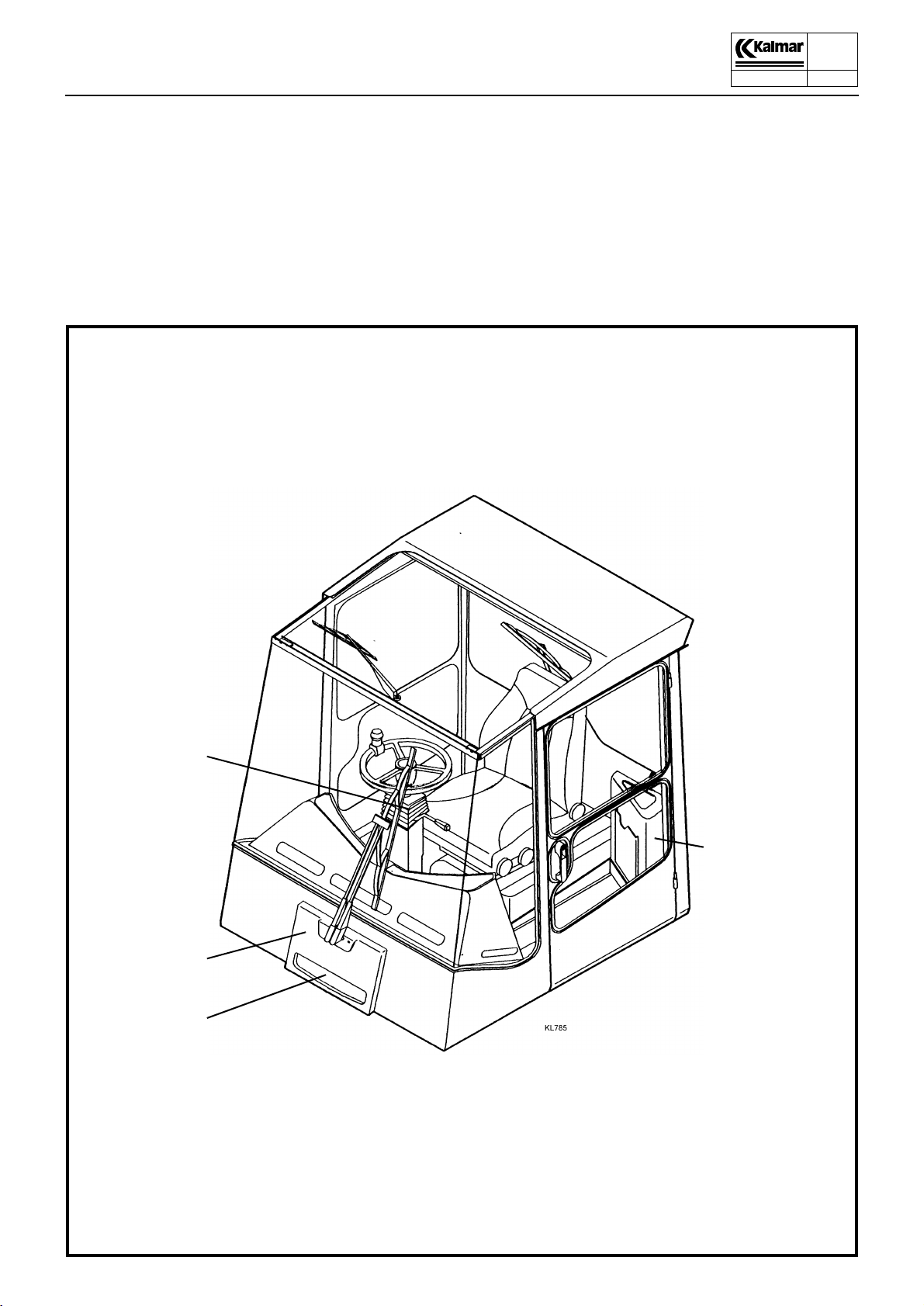
Operator’s cab
The operator’s cab is a separate structure and rests on the chassis on rubber dampers. The operator’s seat, steering wheel and
hydraulic control levers can be adjusted for best possible operator comfort. Effective insulation minimises the vibrations and
sound level in the cab.
The standard heating system consists of a fan and heater for
heating the air in the cab by recirculation. Fresh air is drawn in
through a ventilation air filter. Full air conditioning, with cooling,
heating and dehumidification, is available to special order.
9350
00-11
P.Group 10
4
1
2
3
1. Steering column with instrument panel and switches, ECS-terminal (option)
2. Air filter
3. Heating system
4. Electrical central unit
4

DCD90-180
Technical Handbook
31 4 5 2 6
Operator’s cab
Description
9350
00-11
P.Group 10
5
KL735
1
23
4
F
N
R
R
145
23
L
0
a
bc
d
7
KL743
1. Gear selector
FORWARD/NEUTRAL/REVERSE 1/2/3
2. Lever DIRECTION INDICATORS/HORN
FRONT WINDSCREEN WASHER/
FRONT WIPERS/MAIN BEAM
3. Instrument panel
4. Steering wheel panel
5. Starting switch
6. Control lever, hydraulic functions
a. Lift, b. Tilt, c. Sideshift, d. Fork positioning
8 9 10 11 12 13 14
7. Electrical central unit with fuses and relays
8. Brake pedals, normal driving brake
9. Release clutch
10. Accelerator pedal
11. Steering wheel adjustment
12. Stop control
13. Parking brake
14. Operator’s seat
DCD90-180
Technical Handbook
Operator’s cab
Description
9350
00-11
P.Group 10
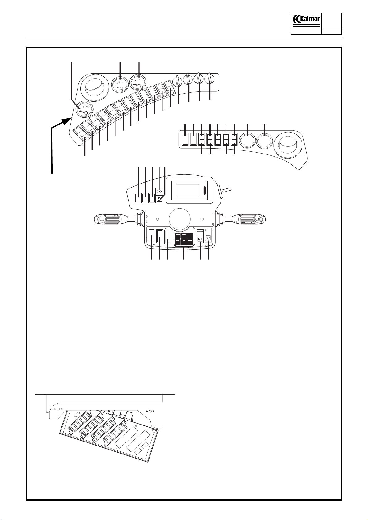
6
66
21
24
25
26
27
28
22
29
1
23
4
30
23
32
31
54
55 56 60 59
F
N
R
33
34
KL581
39
38
37
36
35
40 41 42 43 44 45 52 53
46
47 48 49 50 51
R
1
2
3
4
5
KL580
KL582
L
0
57 58 64 61 62 63
21. Pressure gauge, gearbox oil pressure
22. Fuel gauge
23. Temperature gauge, engine coolant temperature
24. Switch, working lights
25. Switch, working lights
26. Switch, working lights
27. Switch, flashing beacon
28. Switch, hazard warning lights
29. Switch, driving lights
30. Spare
31. Spare
32. Spare
33. Spare
34. Switch, compressor air conditionin
1)
g
35. Control, recirculation/fresh air
36. Control, defrost/cab
37. Switch, fan
38. Control, heat
39. Control, cold
KL675
1)
40. Spare
41. Spare
42. Warning lamp, battery charging
43. Warning lamp, low engine oil pressure
44. Warning lamp, low gearbox oil pressure
45. Warning lamp, low brake pressure
(accumulator pressure)
46. Warning lamp, low engine coolant level
47. Indicating lamp, preheating
48. Warning lamp, high engine coolant temperature
49. Warning lamp, high gearbox oil temperature
50. Spare
51. Warning lamp, parking brake ON
52. Spare
53. Spare
54. Spare (Green lamp TWIST-LOCKS LOCKED)
55. Spare (Orange lamp ALIGNMENT)
56. Spare (Red lamp TWIST-LOCKS UNLOCKED)
57. Spare (LOCK/UNLOCK TWIST-LOCKS)
58. Spare (LENGT ADJUSTMENT 20-40’)
1)
1)
1)
59. Indicating lamp, headlights
60. Indicating lamp, direction indicators
61. ECS terminal
1)
62. Switch, windscreen wiper, rear
63. Switch, windscreen wiper, roof
64. Spare
65. Fuses
66. Hour meter
1)
Optional
1)
1)

DCD90-180
Technical Handbook
Operator’s cab
Description
Steering column
Surrounding the steering column are multi-function levers for
gear changing, indicators, windshield wipers, etc., as well as the
instrument panel with the ECS terminal. At the very foot of the
steering column is the steering valve (Orbitrol), activated by the
steering wheel via an angled gear. The steering column is
equipped with an adjustment handles for the alteration of steering
wheel height and rake.
9350
00-11
P.Group 10
7
1
23
4
1
F
N
R
R
1
2
3
4
5
L
0
2
3
KL580A
4
1. Gear lever
2. Multi-function lever
3. ECS terminal
4. Steering wheel adjustment
handles
5. Angled gear
6. Orbitrol steering valve
KL588
6
5
Steering column
DCD90-180
Technical Handbook
Operator’s cab
Description
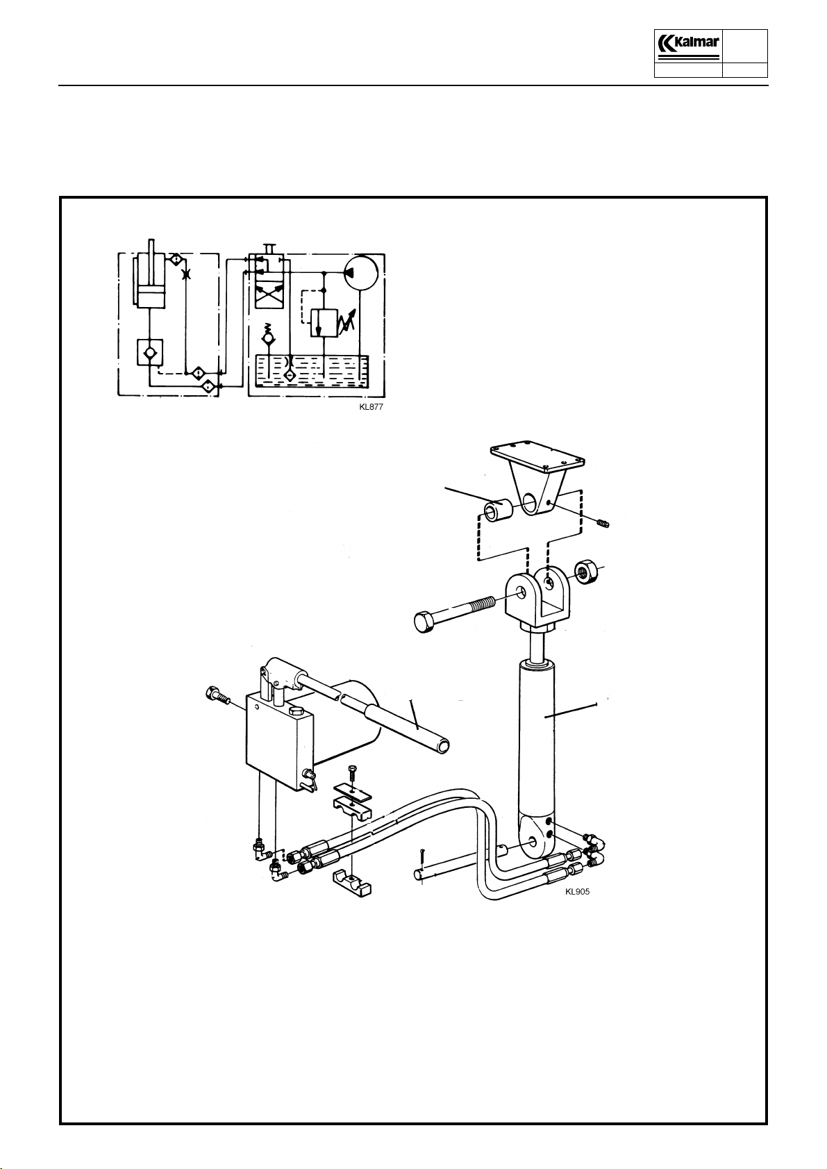
Pump and cylinder for cab tilting
A hydraulic cylinder is provided for tilting the cab. The hydraulic
fluid pressure for this purpose is generated by a manually operated pump. The pump is fitted with a reversing valve for upward or
downward tilting.
9350
00-11
P.Group 10
8
1
2
3
2
4
1. Cab tilting cylinder
2. Manual pump
3. Vibration damper
4. Cab tilting cylinder
Pump and cylinder for cab tilting

DCD90-180
Technical Handbook
Operator’s cab
Description
9350
00-11
P.Group 10
9
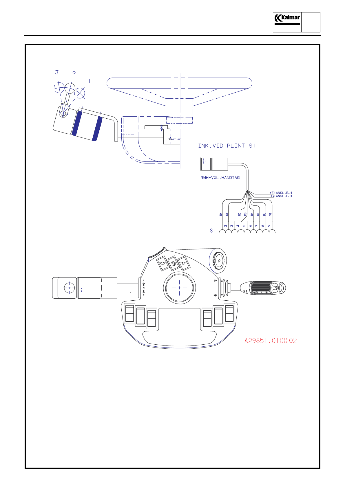
3
1
1. Push-button, reverse gear
2. Push-button, forward gear
3. Microswitch
4. Engagemant and disenagagement of the
foot operated gear changing system
4
2
Accelerator pedal with change-over switches for forward and reverse
DCD90-180
Technical Handbook
Operator’s cab
Description
9350
00-11
P.Group 10
10
Gear selector type RMH
DCD90-180
Technical Handbook
Operator’s cab
Description
1
9350
00-11
P.Group 10
11
4
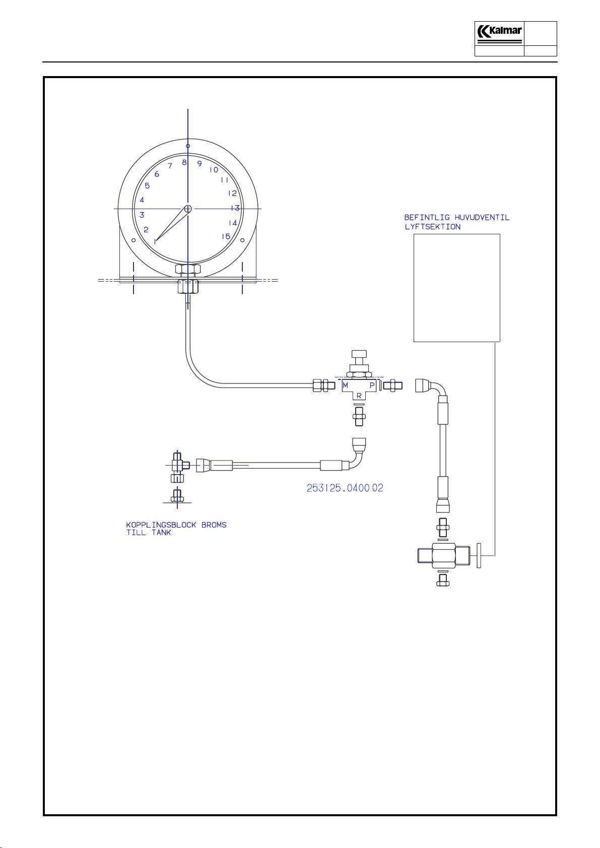
3
2
1. Indicator scale in the cab
2. Tank connection to the brake valve connecting block
3. Foot switch for weighing
4. Connection to the main valve LIFT section
Hydraulic weight indicator
DCD90-180
Technical Handbook
Operator’s cab
Service
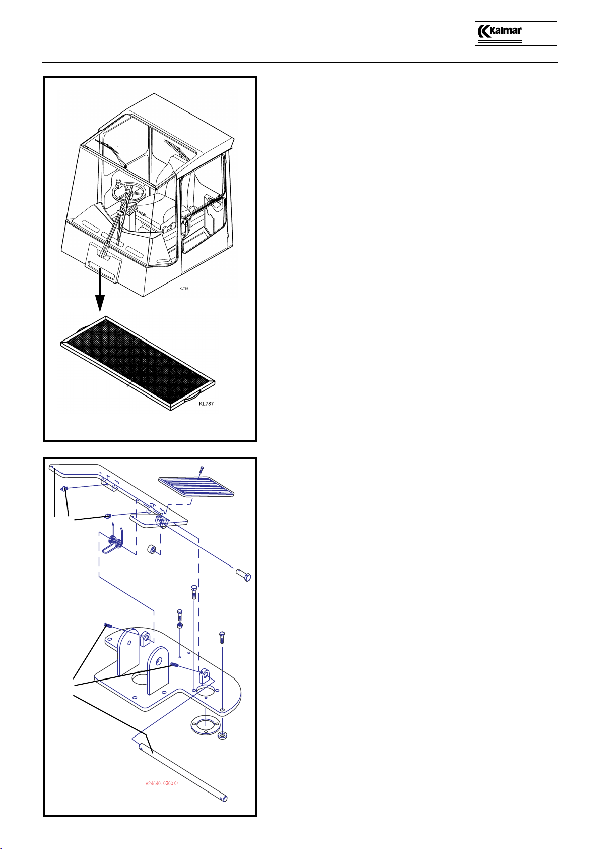
Changing the fresh air filter
(every 200 hours or when needed)
1. Remove the filter casing retaining bolts and remove the filter
element.
2. Wash the filter insert with water and detergent or by using a
high pressure washer. Replace the insert if necessary.
3. Reinstall the filter insert.
9350
00-11
P.Group 10
12
2
1
3
4
1. Brake pedal
2. Lubricating nipple
3. Locking screw
4. Shaft
Check and lubrication of brake pedal
(every 1000 hours)
1. Check and tighten the locking screws 3, so that the brake
pedal is securely fitted in the console.
2. Lubricate the brake pedal shaft through the nipples 2.

DCD90-180
Technical Handbook
Operator’s cab
Service
9350
00-11
P.Group 10
13
Windscreen wipers
The wiper arms are fixed to the wiper motor shafts via conical
splines. The shafts are manufactured of hardened steel and the
wiper arm mounting of soft, pressed metal. When fitting, the nuts
must be tightened so hard that the splines are pressed well into
the mounting and function as a carrier.
Removal
1. Remove the wiper arms by loosening the nuts and thereafter
tapping and carefully rocking the arms to and fro.
Fitting
1. Check to ensure that the splines on the motor shaft are free
from the softer material from the wiper arm mounting.
1
If this is not the case, clean the splines so that they can
pressed fully into the wiper arm mounting.
2. Fit the wiper arms onto the motor shafts and tighten the nuts
to a torque of 16-20 Nm.
Hold the wiper arm to take up the torque pressure so that it
is not transferred to the motor, which could result in damage
.
IMPORTANT!
2
3
The nuts must be tightened sufficiently hard, otherwise
the shafts may start to slip inside the wiper arm mounting,
resulting in damage.
1. Wiper arm fitting
2. Securing nut, wiper arm
3. Grooved cone on motor shaft
4. Wiper motor
4

DCD90-180
Technical Handbook
1
Air conditioning unit
Description
Air conditioning unit
The air conditioning unit consists of the parts shown in the illustration and its function is to maintain the climate in the ope-rator’s cab as comfortable as possible. The air conditioning unit:
z heats the air when it is cold
z dehumidifies the air when it is humid
z removes impurities from the air
z cools the air when it is warm
The equipment is steered by switches and controls on the instrument panel.
5
6
4
9350
00-11
P.Group 10
14
1. Heating control
2. Heat exchanger
3. Vapourizer
4. Expansion valve
5. To condenser
6. To compressor
7. Heating valve
8. From engine
9. To engine
10. Fan
11. Fan
12. Fan control
13. Fresh air filter
14. Air disperser
15. Control defrost/cab
16. Defroster outlet
3
8
9
7
2
15 16
12
14
10
11
13
The heating and ventilating system
DCD90-180
Technical Handbook
Air conditioning unit
Description
9350
00-11
P.Group 10
15
F
2
4
D
C
E
E
3
7
A
B
6
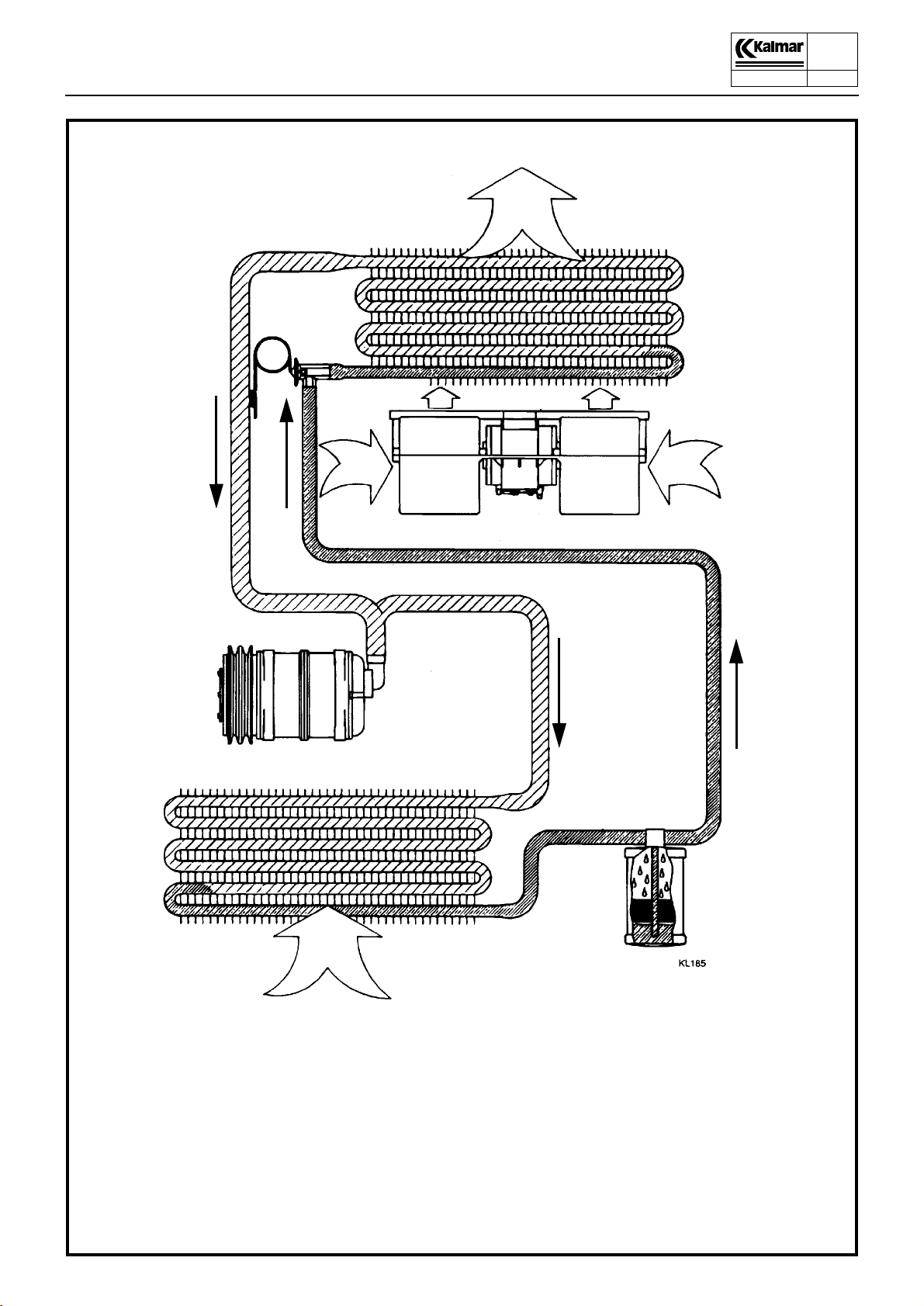
1. Liquid receiver/filter dryer
2. Evaporator
3. Fan
4. Expansion valve
6. Condenser
7. Compressor
1
G
A High-pressure gas
B High-pressure liquid
C Low-pressure liquid
D Low-pressure gas
E Warm air in cab
F Cooled air to the cab
G Outside air for removing heat

DCD90-180
Technical Handbook
Air conditioning unit
Description
Compressor
The air conditioning system is driven by the compressor. This
performs as a pump, drawing cold, low-pressure gas from the
evaporator, compressing it and thereby raising its temperature,
and discharging it at high pressure to the condenser.
The compressor is driven by V-belts directly from the diesel engine. Switching between operation and idling is controlled by an
electro-magnetic clutch which, in turn, is controlled by a thermostat whose sensor is located between the fins of the evaporator
coil. The thermostat switches off the compressor at low temperatures, to prevent icing of the evaporator.
Condenser
The function of the condenser is to convert the hot high-pressure
gas from the compressor into liquid form. The tubes and fins of
the condenser coil absorb heat, which is then removed by the air
delivered by the fan.
The temperature of the refrigerant in the condenser varies from
about +50°C to +70°C. The pressure varies between 12 and 20
bar, depending on the ambient temperature and the flow of air
through the condenser. When the refrigerant is condensed into
liquid form, it is transferred under pressure to the liquid receiver/
filter dryer.
9350
00-11
P.Group 10
16
Liquid receiver with filter-dryer
The function of the liquid receiver with integrated filter dryer is to
collect the liquid coolant, bind the moisture, and to filter and remove impurities. The receiver, which is located in the condenser
housing, also serves as the expansion vessel in the refrigeration
circuit.
After flowing through the dryer in the bottom of the liquid receiver,
the refrigerant flows through a riser tube. A sight glass enables
the operator to check that the liquid flows without the presence of
any bubbles, and that the system is filled with a sufficient amount
of refrigerant.
Expansion valve
The expansion valve throttles the flow and passes an optimised
quantity of refrigerant that the evaporator is capable of evaporating.
The expansion valve is also the part of the circuit which separates
the high- pressure side from the low-pressure side. The refrigerant flows to the expansion valve under high pressure and leaves
it under low pressure.
The amount of refrigerant which passes the evaporator varies,
depending on the thermal load. The valve operates from ’fully
open’ to ’fully closed’ and in-between searches for a point to give
optimum evaporation.
Evaporator
The heat necessary for evaporating the refrigerant is extracted
from the cab air which is circulated by a fan through the evaporator coil. The cab air is thus cooled, and is distributed and returned
to the cab.
In the evaporator, the refrigerant reverts to the gaseous state and
returns to the compressor suction, thereby completing the cycle.
 Loading...