


OPERATOR’S MANUAL

Warning
Battery posts, terminals and related
accessories contain lead and lead
compounds, chemicals known to the
State of California to cause cancer
and reproductive ha rm. W a sh hands
after handlin g.
Proposition 65, a Califo rnia law, requires warnings
on products which expose individuals in California
to chemicals listed under that law, including
certain chemicals in diesel engine exhaust.
California
Proposition 65 Warning
Diesel engine exhaust and some of
its constituents are known to the
State of California to cause cancer,
birth defects, an d other reproductive
harm.

KALMAR
OPERATOR’S MANUAL
NOTICE
The information in this manual was current at the time of publication. Contents of this manual are
subject to change at the publisher’s discretion.
DO NOT REMOVE THIS MANUAL FROM THE VEHICLE. STUDY THIS MANUAL. READ AND COMPLY
WITH ALL WARNINGS IN T HIS MANUAL. IF THE VEHICL E IS SOLD, GIVE THIS MANUAL TO THE NEW
OWNER.
Kalmar Solutions, LLC
415 East Dundee Street
Ottawa, Kansas USA
(785) 242-2200
Fax (785) 242-6177

Notes
Notes

Table of Contents
Table of Contents
Foreword ...................................................................................................................................................... ...... ..... 1
From Kalmar to the Owner ................................................................................................................ ....... ...... ..... 1
About the Operator’s Manual ..................................... ....... ...... ...... ....... ...... ....... ...... ....................................... ..... 1
1 Introduction ................................................................................................................................... ...... ....... ...... ..... 2
1.2 Safety Summary ....................................................................................................................................... ..... 2
CAUTIONS and WARNINGS .......................................................................................................................... 2
NOTICES ............................... ....................................................................... .................................................. 2
1.5 Vehicle Towing ......................................................................................................................................... ..... 2
Towing Vehicle with Front Wheels Suspended ............................................................................................... 3
Towing Vehicle with Rear Wheels Suspended .......................................................................................... ..... 3
1.6 Vehicle Modifications .......................................................................................................................... ...... ..... 4
1.7 Safety Checks and Precautions .................................................................................................................... 4
Inspection ........................ ............. ............. ............. ............. ............. ............. ............. ............. ...... ....... ...... ..... 4
Axle — Front ............................................................................................................................................... 5
Axle — Rear ............................................................................................................................. ....... ........... 5
Brake System ........................................................................................................................... ....... ...... ..... 5
Cab ........................................................................... ....................................................................... ...... ..... 6
Seat Belt System ........................................................................................................................................ 6
Electrical ............................................................ ....................................................................... ....... ...... ..... 7
Exhaust System .................................................................................................................. ...... ....... ........... 8
Frame .......................................................................................................................... ...... . ...... ....... ...... ..... 8
Fuel System ................................................................................................................................................ 8
Propeller Shaft ................................................................................................................................ . ...... ..... 8
Steering ...................................................................................................................................................... 8
Suspension ................. .................................................... ............................................... ............................. 9
Transmission .............................................................................................................................................. 9
Wheels/Tires ............... .................... ................... ................... .................... ................... ............. ....... ...... ..... 9
1.8 Additional Manuals and Safety Informati on ................. ...... ...... ....... ...... ....... ...... ....... ...... ....... ...................... 11
1.9 Service Assistance ...................................................................................................................................... 12
3 Description and Operation .................................................................................................................................. 13
3.1 Cab/Deck .................................................................................................................................................... 13
Vehicle Entry and Exit ................................................................................................................................... 13
3.1.3 Cab Tilting ............................................................................................................................................ 14
To Tilt Cab ................................................................................................................................................ 15
To Lower Cab ........................................................................................................................................... 16
3.1.4 Seating ................................................................................................................................................. 17
Suspension-Type Seats ........................................................................................................................... 17
Seat Adjustment ....................................................................................................................................... 17
3.1.5 Instrument Panel Gauges, Controls and Indicators ............................................................................. 18
Instrument Panel Overview ...................................................................................................................... 18
3.1.6 Electrical Equipment ............................................................................................................................ 26
Accessory Connections ............................................................................................................................ 26
Relays/Breakers/Fuses ............................................................................................................................ 26
3.1.9 Occupant Restraint System ................................................................................................................. 29
Seat Belt Operation .................................................................................................................................. 29
3.2 Chassis ....................................................................................................................................................... 29
3.2.2 Powertrain ............................................................................................................................................ 29
Engine ...................................................................................................................................................... 29
Transmission ............................................................................................................................................ 32
Axles ........................... .................................................... .......................................................................... 32
3.2.4 Air System and Brakes ...................................................................................................
Air Pressure Indicators ...................................................................................................................... 34
Low
Service Brakes ........................ ....... ............................................. ...... ....... ...... ....... ...... ............................. 35
ABS .......................................................................................................................................................... 36
Traction Control ........................................................................................................................................ 36
Parking Brake ........................................................................................................................................... 37
Parking Brake and Trailer Air Supply Controls ......................................................................................... 37
Parking the Vehicle ................................................................................................................................... 37
..................... 33
i

Table of Con t ents
Manually Releasing Tractor Spring Brakes (Caging) ............................................................................... 38
Trailer Brakes ........................................................................................................................................... 39
Trailer Air Lines ........................................................................................................................................ 39
3.2.5 Hydraulic System ................................................................................................................................. 40
Hydraulic Fifth Wheel Lifting System ........................................................................................................ 40
Hydraulic Boom Operation ....................................................................................................................... 40
Fifth Wheel Unlatch Control Valve ............................................................................................................ 40
Basic Trailer Spotting Steps ..................................................................................................................... 41
3.2.7 Exhaust System — DOT/EPA-Approved Engines ............................................................................... 43
Diesel Particulate Filter (DPF) Regeneration ........................................................................................... 43
Exhaust-Related Engine Indicato r Lam ps ......................................... ....... ...... ....... ...... ....... ...... ................ 45
6 Scheduled Maintenance ..................................................................................................................................... 47
General Maintenance Program ......................................................................................................................... 47
6.1 Checklists .................................................................................................................................................... 48
Chassis Lubrication Diagram ................................................................................................................................. 48
Boom and Fifth Wheel Lubrication Diagram ................................................................................................. 49
Lubrication and Fluids ................................................................................................................................... 52
Automatic Transmission Fluid .................................................................................................................. 53
Axle Differential Lubricant ......................................................................................................................... 53
Coolant/Anti-Freeze ........... ................... .................... ................... ................... .......................................... 53
Fuel ............................. ............. ............. ............. ............. ............. ............. ............. ................................... 54
Engine Oil ................................................................................................................................................. 55
Diesel Exhaust Fluid (DEF) ...................................................................................................................... 55
Hydraulic System Fluid ............................................................................................................................. 56
Multi-Purpose Grease ............................................................................................................................... 56
Filters ............................................................................................................................................................ 56
Preventative Maintenance Guidelines .......................................................................................................... 57
Cab Interior ............................................................................................................................................... 57
Check HVAC System ............................................................................................................................... 58
Seat Belt System ...................................................................................................................................... 59
Cab Down — Exterior ............................................................................................................................... 60
Cab Up ..................................................................................................................................................... 61
Under Vehicle ........................................................................................................................................... 63
Chassis .............................. ............................................. ............................................ .............................. 64
Lubrication ................................................................................................................................................ 65
Test Drive ................................................................................................................................................. 66
7 Environment ....................................................................................................................................................... 67
General ............................................................................................................................................................. 67
Environmental Policy ......................................................................................................................................... 67
Environmental Awareness ................................................................................................................................. 68
Environmental Problems ................................................................................................................................... 68
Laws and Regulations ....................................................................................................................................... 68
Use of Materials and Energy ................... ...... ....... ...... ............................................. ....... ...... ... .......................... 69
Effects of Exhaust Gases .................................................................................................................................. 69
Recycling ....................... ................... .................... ................... ................... ....................................................... 70
Complete Overhaul or Disposal ........................................................................................................................ 70
Problem Waste .................................................................................................................................................. 71
Oils and Fluids .................................................................................................................................................. 71
Air Conditioning ................................................................................................................................................. 71
Occupational Health and Safety ........................................................................................................................ 72
Working In an Environment That is Hazardous To the Health .....................................................................
ember ........................................................................................................................................................ 72
Rem
Standards .......................................................................................................................................................... 73
Vibration Affecting the Hands ................................................................................................................... 73
Vibration Affecting the Whole Body .......................................................................................................... 73
Noise Levels ............................................................................................................................................. 73
CE Marking ..................................................................... ....... ...... ...... ....... ...... .......................................... 73
Exhaust Gas Emissions ............................................................................................................................ 73
...... 72
ii

Foreword
NOTICE
NOTICE
Foreword
Foreword
From Kalmar to the Owner
The manufacturer of these trucks cannot create a single
manual that would cover every option available.
We have tried to cover all the information that would be
included in a normally configured truck.
For information on some major components, you will need to
refer to the component manufacturer’s literature.
About the Operator’s Manual
The intent of this Operator’s Manual is to provide basic
information on the safe operation of the Kalmar tractor.
The Introduction section contains important informa tion
regarding the use of safety messages as indicated by the
signal words “Danger,” “Warning,” “Caution” or “Notice” that
are found throughout this manual. This section also contains
important safety and service support information.
The Description and Operation section provides infor mati on
about the features of the tractor and basic operating
information for the tractor itself.
The Scheduled Maintenance section covers basic opera t or
maintenance and lubrication information.
Remember that the safe operation of the Kalmar tractor
depends entirely on the operator. The operator of this vehicle
must be properly trained and fully knowledgeable BEFORE
attempting to operate it. Read this manual carefully and pay
close attention to all warnings, cautions and notices. Keep this
manual in the vehicle and make sure it goes to the new owner
if the truck is sold.
Because of the many variations and options associated with
Kalmar tractors, some optional equipment on your vehicle
may not be covered in this manual. If there are any questions
regarding the specific options or variations not covered in this
manual, contact your nearest Kalmar dealer for assistance.
The Kalmar tractor may also be referred to throughout this
manual as “vehicle” or “the vehicle”. Throughout this manual
reference is made to “Operator”. In the context of this
manual, the “Operator” refers to the actual driver of the
vehicle.
1
1 Introduction
NOTICE
NOTICE
1 Introduction
1 Introduction
1.2 Safety Summary
CAUTIONS and WARNINGS
Throughout this manual you will find Warnings and Cautions.
DANGER indicates a hazardous situation which, if not
avoided, will result in death or serious injury.
WARNING indicates a hazardous situation which, if not
avoided, could result in death or serious injury.
CAUTION indicates a hazardous situation which, if not
avoided, could result in injury.
NOTICES
Throughout this manual you will see Notices. Notices will be
used to show special procedures or point out important facts.
Notices will also designate important information regarding
this manual and its use.
1.5 Veh ic l e Tow in g
Towing a vehicle requires special equipment and training.
Kalmar Solutions, LLC, recommends that a professional towing
service be used whe n t owin g a d isa bl ed Kalm ar tra cto r.
The best way to tow a Kalmar tractor is with the rear wheels
lifted off the road. This prevents any possible damage to the
transmission and drivetrain. Towing the vehicle with the rear
wheels lifted avoids having to disconnect the driveline or axle
shafts. Also, towing with the rear wheels lifted does not require
the spring brakes to be caged unless there are spring brakes
on the front wheels.
2
If it is impossible to tow the vehicle with the rear wheels lifted,
be sure to follow the steps listed below, “Towing Vehicle with
Front Wheels Suspended”.
Some vehicles are equipped with “Off Highway” tires. Tire
damage may occur if towed on the road.
1 Introduction
Towing Vehicle with Front
Wheels Suspended
It is not recommended to tow a vehicle with the front wheels
lifted and the rear drive wheels on the road. This practice may
result in serious vehicle damage. Pay close attention to the
following rules to prevent vehicle damage if you must tow your
Kalmar tractor with the rear wheels on the road.
Always obey the following when towing a Kalmar tractor
with the front wheels lifted and the rear wheels on the
road. Failure to do so could result in death or serious
injury.
1. Always use a rigid towing bar or properly restrain the
towed vehicle. Using a chain or cable to tow the
vehicle is not recommended.
2. Always disconnect the driveline to the rear drive
axle(s), or remove all axle shafts from all rear drive
axles.
3. Always cage the spring brakes on all rear drive wheels.
[See page 38, Manually Releasing Tractor Spring
Brakes (Caging).] A loss of air pressure could occur
while towing the vehicle. This would apply the spring/
parking brakes and lock the rear wheels on the towed
vehicle.
When manually releasing the spring brakes, make sure
that the vehicle wheels are properly blocked. If the wheels
are not blocked, the vehicle could move suddenly when
the spring brakes are released and cause death or severe
injury.
If the disabled vehicle is connected to a tow vehicle before
the spring brakes are released, make sure that the tow
vehicle’s parking brakes are applied and its wheels are
blocked to prevent movement. Failure to do so could
result in death or serious injury.
Towing Vehicle with Rear
Wheels Suspended
The recommended way to tow a disabled vehicle is with the
rear wheels lifted off the ground. The steering axle must be
locked in the straight-ahead position. If there are spring brakes
on the front axle, the springs must be caged. [See page 38,
Manually Releasing Tractor Spring Brakes (Caging).]
3

1 Introduction
1.6 Vehicle Modifications
Do not make modifications to your Kalmar tractor without
written approval from Kalmar Solutions, LLC. Your vehicle has
been designed and manufactured with safety and reliability in
mind. Any modifications by the operator or owner could
decrease the safety and reliability of your vehicle. Any
unauthorized vehicle modifications may also void the Kalmar
Solutions, LLC Limited Warranty. Do not risk personal safety or
vehicle reliability by making unauthorized modifications to your
Kalmar tractor. Contact Kalmar Solutions, LLC concerning any
proposed modifications to this vehicle.
1.7 Safety Checks and
Precautions
All spotting applications are demanding on the vehicle.
Maintenance is critical for the continued SAFE performance of
your tractor. Before operating your Kalmar tractor, it is
essential that the vehicle is in proper and safe working
condition.
The following section is intended to provide a basic knowledge
of important safety check procedures. These checks must be
performed regularly to ensure safe vehicle operation. The
frequency of these checks depends on the application of the
vehicle.
In general, the best time to make the following safety checks
would be during normal maintenance and during daily PreOperation Safety Inspections.
All operators should comp let e a Kalmar Daily Inspection
before climbing into the driver’s seat. This “Walk Around” is a
good way to prevent potential problems. A sample daily
inspection form is provided on page 10 of this section. Use this
as a guide to come up with an appropriate checklist for your
individual vehicle.
When performing inspections, always park the tractor on a
level surface, apply the parking brakes and chock the wheels.
Inspection
4
If the vehicle is used in a severe application, such as a rail
yard operation or in 24-hour operations, a more frequent
schedule should be followed. Failure to maintain the
vehicle on an appropriate schedule can lead to
component damage or injury.

1 Introduction
During each scheduled maintenance interval or at least once a
month, a qualified mechanic should inspect all of the following
areas.
Axle — Front
Maintaining correct front axle alignment is critical and should
be performed by a qualified mechanic.
Check to ensure that the axle mounting bolts are securely
tightened. Regularly check the front axle for damage, binding
or worn parts, and adequate lubrication. Pay special attention
to the axle stops and rubber snubbers. Do not operate the
vehicle without the proper axle stops in place.
Axle — Rear
Check to ensure that the axle mounting bolts are securely
tightened. Regularly check the rear axle for damage and oil
leaks. Unusual noises and signs of extreme heat may indicate
axle damage.
Brake System
Do not operate the vehicle until the brake system has
been thoroughly inspected. Failure to conduct a complete
Kalmar Daily Inspection prior to operation could lead to
serious injury or death.
Check the following:
1. Check brake controls for proper operation. Make sure the
foot-operated treadle in the cab is operating smoothly and
is not damaged.
2. Visually inspect the brake drums, brake chambers, and
slack adjusters. Check for loose, missing or broken
components. Check brake chambers and slack adjusters
for cracks and other signs of severe wear.
3. Listen for air leaks in the cab and underneath the chassis.
Check air pressure regularly using the dash-mounted
gauge. Be alert for any sudden drops in pressure while
operating the vehicle and after the engine is shut off. A
minimum air pressure of 70 P.S.I. (4.83 bar) is required to
operate this vehicle.
4. Visually check hoses and pneumatic lines for damage and
chafing.
5. Check the operation of both the service and parking brake
systems. Be alert for any reduction in braking performance
or unusual noises while braking.
5
1 Introduction
Cab
Defroster — Operate the defroster to make sure sufficient air
is being directed against the windshield. Make sure the blower
is operating before the weather requires the defroster.
Door Latches — Check for positive closing, latching and
locking.
Walkways/Steps — Check to ensure that all factory-installed
walkways, platforms and steps are installed onto the vehicle
securely and are not damaged or loose. Make sure that all
walkways, platforms and steps are free of dirt, debris, ice, mud
and any other potentially hazardous obstructions.
Handholds/Grab Handles — Check to ensure all handholds
are installed and are not loose or damaged.
Glass — Check for cracked, broken, scratched or dirty glass.
Cleaning Instructions for Optional Plastic Glazing — Wa sh
windows with a clean sponge or soft cloth using lukewarm
water and mild detergent or window cleaner. Rinse with clean
water. Do not use abrasive or highly alkaline cleaners. Never
scrape with squeegees, razor blades or other sharp
instruments. Remove ice and frost with the cab heater/
defroster or by applying heat.
Mirrors — Check to be certain all mirrors are installed and that
they are clean, undamaged and properly adjusted.
Seat Belt System
Always check the seat belt system for wear and proper
operation. All components must be in good condition and
ready to function correctly when necessary. Failure to
check the seat belt system could lead to serious injury or
death.
Inspect the seat belt system every 20,000 miles (32,187 km) or
more often if exposed to severe environmental conditions or
vocation. Check the following:
1. Inspect belt on entire system for cuts, fraying, extreme or
unusual wear. Most common areas of belt wear include the
buckle/latch area, the shoulder loop area and any place
where the bel t mak es contact with vehicle or seat. Replace
the entire belt system if necessary.
2. Inspect buckle for proper operation by inserting latch and
listening for an audible click. Verify the buckle is not
damaged, cracked or broken. Replace the entire belt
system.
6
3. Inspect buckle cable (optional component) black coating
on buckle cable must not be damaged. Internal cable wires
must not be exposed, frayed or broken. Replace the entire
system.

1 Introduction
4. Inspect latch for proper operation by inserting into buckle.
Latch must insert smoothly and you must hear an audible
click. Verify proper latching by tugging on belt. Latch must
not be worn, deformed or corroded. Replace the entire belt
system.
5. Inspect shoulder loop web guide (optional component)
Seat belt must move freely through shoulder loop.
Shoulder loop must also pivot freely and be free of
obstructions. If necessary, adjust shoulder loop hardware
and/or remove obstruction.
6. Inspect seat belt height adjuster (optional component)
for damage. Mover adjuster up and down. It must move
freely and lock at the di ff erent heig ht pos ition s. Replace the
entire belt system if necessary.
7. Inspect retractor operation. When pulled and released
slowly, seat belt must spool out and retract without locking.
Replace the entire belt system if necessary.
8. Inspect mounting hardware on both sides of seat.
Hardware should be tight. Hardware must not be missing,
rusted, corroded or damaged. If necessary, replace
defective or missing hardware with authorized parts and/or
tighten hardware.
9. Inspect tethers for cuts, fraying, extreme or unusual wear.
Tethers must also be inspected for proper attachment and/
or adjustment. If necessary, replace defective tethers.
Tighten and/or properly adjust tethers according to the
Seat Adjustment section on page 17.
®
10.Inspect Komfort Latch
and ability to clamp on web. Replace the entire system if
necessary.
Cleaning of Seat Belt Fabric — Sponge the seat belt clean
with mild soap and water. DO NOT use bleach, dye or
household detergents.
(optional component) for function
Electrical
Horn — Operate the steering wheel-mounted horn to check
operation. (Check optional air horns if equipped.)
Instruments — Check operation of all instruments and
gauges.
Lights — Check to make sure all lights (interior, exterior,
headlights, etc.) function properly. Make sure the gauge and
dash backlighting is working prop er ly.
Wiring — Check to ensure all wiring is properly secured and
protected. Replace worn, cracked or chafed wires and looms.
Make sure factory wiring has not been compromised by
improper splicing o r modifi ca tions.
7

1 Introduction
Exhaust System
Maintain the exhaust system (mufflers, pipes, stacks, joints)
integrity to ensure no exhaust fumes can enter the cab. Look
for loose, damaged or missing exhaust components. Be alert
to any exhaust fumes or unusual odors in the cab.
Frame
Check for cracks and signs of damage. Pay close attention to
highly stressed areas of the frame such as the boom piv ot
area. Contact your dealer for instructions on frame repair. Do
not weld on frame rails unless directed to do so by your Kalmar
dealer or by the factory.
Fuel System
The throttle should operate smoothly and with minimal effort.
Always replace damaged throttle components with factory
replacement parts.
Check the fuel system for leaks and hose chafing. Repair any
problems before operating the vehicle.
Check the DEF system for leaks and hose chafing. Repair any
problems before operating the vehicle.
Propeller Shaft
Check the universal joints for wear. If propeller shaft vibrations
occur, stop the vehicle immediately to prevent serious damage
to the vehicle drivetrain.
Steering
Be alert to any change or feel in steering while driving the
vehicle. This change or feel may include a change in steering
effort, unusual sounds when turning, or excessive wheel play
or pulling to either side.
If a problem is suspected or felt, check steering components
for loose, damaged or worn parts. All steering components
such as the tie rod and drag link must be tight.
Check the power steering system for leaks and hose chafing.
Repair any problems before operating the vehicle. Regularly
inspect all steering linkages.
8
Do not operate the vehicle with broken, damaged, worn or
non-OEM steering system components. If the Kalmar
Daily Inspection reveals any of these issues, have the
vehicle repaired immediately by a qualified technician.
Failure to do so could result in serious injury or death.

1 Introduction
NOTICE
Suspension
Check the condition of the front and optional rear (if
installed) suspension components such as mounting
brackets and bushings. Check for worn and damaged
parts. Failure to do so could result in injury.
Check and maintain the specified torque on all mounting bolts
and nuts. Check the springs and replace broken or distorted
springs.
Transmission
Follow the transmission manufacturer’s guidelines for proper
maintenance.
Wheels/Tires
Check the condition and maintain the specified torque on all
wheel mounting nuts. Replace missing or broken studs and
nuts. Check tire inflation and wear. Do not operate this vehicle
with badly worn or damaged tires. Do not operate this vehicle
with damaged wheels.
Because of the many options available on Kalmar tractors, it
is critical that the owner be aware of all options that may
affect the safe operation of the vehicle and take appropriate
measures to maintain his/her specific vehicle. Always contact
your Kalmar dealer if any questions arise regarding safe
operation of this vehicle.
9

1 Introduction
Kalmar Daily Inspection Form
(Walk Around Inspection)
_____ Check tires and wheels for damage and proper inflation.
_____ Check cab hold down latch (air suspension unit) for proper latching.
_____ Check all fluid levels: engine oil, hydraulic and coolant.
_____ Drain any moisture from air tanks.
_____ Check cab doors and latches for proper operation.
_____ Ensure that all steps, walkways and handholds are installed and in good working order.
_____ Start engine and check transmission fluid level with parking brake applied and transmission shift selector
in “neutral”.
_____ Check windshield wiper for proper operation.
_____ Check steering system for any binding. Make sure steering effort is smooth and light.
______ Check accelerator for proper operation. The accelerator should operate smoothly.
_____ Check all rear view mirrors; adjust and clean if needed.
_____ Check cab and frame for any structural damage or cracks.
_____ Inspect trailer electrical cable and trailer air lines for damage. Make sure both air lines are installed.
_____ Clean all windows if needed.
_____ Check transmission shift lever for proper operation.
_____ Check boom control lever for proper operation.
_____ Check all lights for proper operation: headlights, turn signals, brake lights, hazard lights and marker lights.
_____ Check horn(s) for proper operation.
_____ Check and fill fuel tank.
_____ Drain fuel water separator.
_____ Check and fill DEF tank.
10

1 Introduction
1.8 Additional Manuals and
Safety Information
Kalmar Solutions, LLC offers an Operator Orientation Video
DVD. This video covers important information that all Kalmar
operators must know. The video should be used in conjunction
with this manual to instruct the operator on the proper
operation of the Kalmar tractor. Shipped with every tractor, this
video is also available through your Kalmar dealer or directly
from Kalmar Solutions, LLC.
Figure 1
Operator Orientation Video
11

1 Introduction
1.9 Service Assistance
Kalmar Solutions, LLC has an established dealer network
throughout the world. Whenever assistance is needed, contact
your local dealer first. For contact information, visit our website
at Kalmarind.com or contact Kalmar sales.
When parts or service are required, always have the serial
number of the vehicle ready before contacting your Kalmar
dealer. The serial number is located on an ID plate inside of
the cab.
Kalmar is proud to have been the leader in the Port and
Terminal Tractor Industry for over 50 years. We strive to serve
our customers in every way possible. Thank you for buying our
Kalmar tractor. We know it will serve you well for many years.
If, for any reason, you are not able to obtain assistance from
any Kalmar dealer, feel free to contact Kalmar Solutions, LLC
directly.
For assistance call:
Kalmar Solutions, LLC
Service Department
USA +1 (785) 242-2200
Europe +358 (0) 20 777 5000
12

3 Description and Operation
3 Description and Operation
3 Description and
Operation
The following section on Description and Operation should
be read carefully. It covers important information that every
operator must know before operating any Kalmar tractor.
This manual is intended to cover the standard Kalmar tractor
and some of the most common options. Not all of the
customer-ordered optional equipment or systems are covered
in this manual. If the operation of any component or system on
your vehicle is not covered in this manual, call your Kalmar
dealer for assistance.
All individuals who operate this vehicle must have
sufficient training to operate this type of vehicle and
should have a valid commercial driver’s license. This
manual is not intended to be a training guide for yard
tractor operation. It is the operator's responsibility to
obtain sufficient training in order to operate this vehicle
safely. DO NOT ATTEMPT TO OPERATE THIS VEHICLE
WITHOUT ADEQUATE TRAINING. OPERATING THIS
VEHICLE WITHOUT ADEQUATE TRAINING COULD
RESULT IN SERIOUS INJURY OR DEATH.
3.1 Cab/Deck
Vehicle Entry and Exit
The Kalmar tractor is designed for easy entry and exit. The
walkways, steps and handholds are designed with operator
safety in mind. As with any vehicle of this type, care must be
taken when climbing in or out of your Kalmar tractor.
Remember, be careful!
Always exercise caution when entering or exiting the
vehicle. To avoid serious injury or death, read the
following instructions and warnings before entering and
exiting the vehicle.
1. Entry and exit should be made slowly and carefully.
2. A three-point stance should be used. Three out of the
four extremities (hands and feet) should be in contact
with the vehicle at all times.
3. Face inward toward steps when entering and exiting.
4. Keep steps, walkways and handholds in good condition.
5. Keep steps, handholds, walkways and shoes free of
grease, mud, dirt, fuel, ice and snow.
6. Use extra care during bad weather, especially when
steps and handholds may be icy or wet.
13
3 Description and Operation
Do not remove or modify factory-installed walkways,
steps or handholds. Do not operate your v ehicle unless all
of the factory-installed steps, walkways and handholds
are installed and in good working condition. If the
walkways, steps or handholds have been modified or
removed, or are not in good working order, anyone
attempting to enter or exit the vehicle could be injured or
killed.
3.1.3 Cab Tilting
The tractor comes equipped with an electrically operated cab
tilt system as standard equipment. Under power assist, the cab
can be tilted to 45 degrees. At 45 degrees, the safety prop is
automatically engaged.
The cab can be tilted MANUALLY to 90 degrees if needed.
This requires that the tilt cylinder be disconnected, and that a
suitable hoist be used to tilt the cab all the way to the 90degree position.
All tractors come standard with a cab air suspension. These
units are designed to work with the power cab tilt, and unlatch
automatically.
The electric cab tilt is designed to tilt the cab to 45 degrees at
which point the cab safety prop is automatically engaged. The
tilt system is not designed to provide a safety prop at any point
other than 45 degrees. Figure 3 shows proper engagement
of the cab safety prop.
Never work under the cab unless the safety prop is
properly engaged. The cab could fall and cause serious
injury or death. (See Figure 3 and Figure 4.)
Only tilt the cab far enough past the 45-degree point to
engage the safety bar. Attempting to fully extend the
cylinder past 45 degrees can cause pump and motor
damage. Check the cab tilt cylinder and bracket mounting
bolt for proper torque and wear! Failure to check and
operate the cab tilt system correctly can result in injury.
14
3 Description and Operation
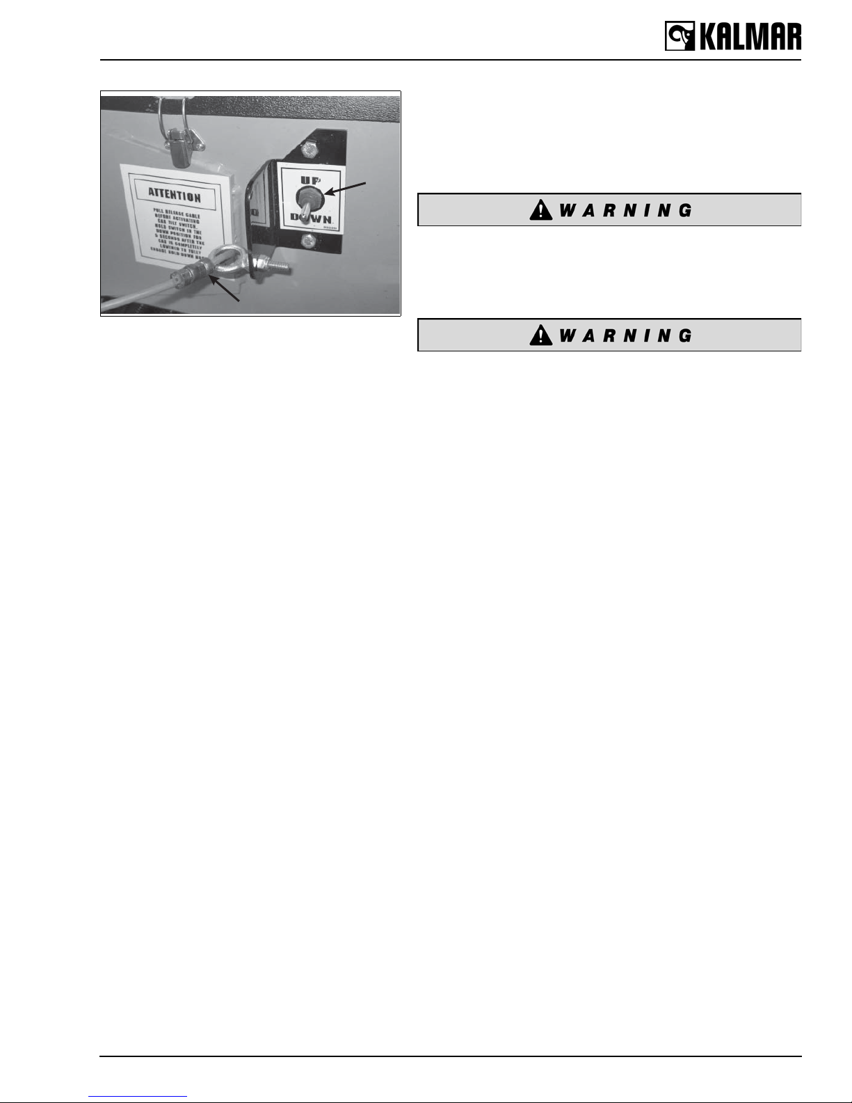
A
B
Figure 2
A — Cab Tilt Control Switch
B — Safety Prop Release Cable
To Tilt Cab
In most cases, the cab tilt control switch is located on the lefthand frame rail (Figure 2). The safety prop release cable is
located on the left-hand rail, within reach of the tilt switch.
Ensure that no part of the body is under the cab while
tilting. Stand clear of the rear of the cab and ensure that
the cab does not strike you when it is being raised. Failure
to do so can lead to serious injury or death.
Ensure that the safety prop is properly engaged before
working under the cab. The safety prop must be able to
move freely to engage automatically. Always check the
safety prop before working under the cab and make sure
to properly maintain this important safety system. Failure
to do so can result in serious injury or death.
1. Locate the cab tilt control switch and safety prop release
cable.
2. Pull the safety prop release cable and hold the cable to the
rear.
3. While holding the cable to the rear, move the tilt control
switch to the UP position.
4. After the cab has traveled about 15 inches (381 mm),
release the safety prop cable and continue tilting the cab.
5. As the cab approaches the 45-degree position, watch for
the safety prop to drop over the tilt cylinder on the driver’s
side of the frame. (Figure 3 and Figure 4) STOP!
6. After the safety prop has dropped over the cylinder, move
the tilt control switch to the DOWN position (Figure 2) and
lower the cab slightly until the safety prop rests fully on the
top of the tilt cylinder (Figure 3).
7. Make sure that the safety prop is resting properly on top of
the tilt cylinder. Pull on the safety prop release cable and
ensure that the safety prop is secure. It should not move
with the weight of the cab on the prop.
15
3 Description and Operation
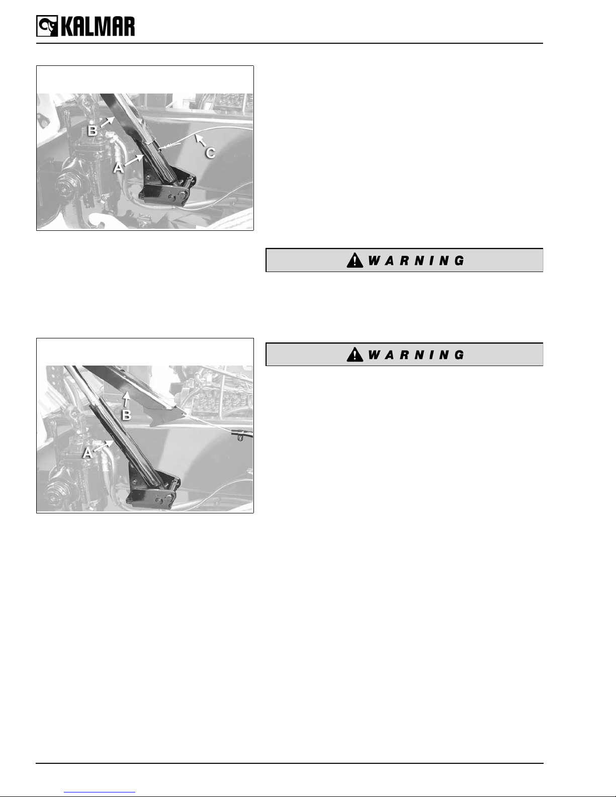
CAB SAFETY PROP IS ENGAGED
CORRECTLY
Figure 3
A — Tilt Cylinder
B — Safety Prop
C — Safety Prop Release Cable
The Safety Prop (B) is resting flush against the
Tilt Cylinder (A). The Safety Prop is properly
engaged.
CAB SAFETY PROP IS NOT ENGAGED
CORRECTLY
To Lower Cab
1. Move the cab tilt switch to the UP position and raise the
cab slightly until the safety prop is free from the top of the
tilt cylinder.
2. Pull the safety prop release cable to the rear and hold in
the rearward position.
3. Move the tilt switch to the DOWN position with the safety
prop disengaged and allow the cab to lower onto the rear
cab latch.
4. Hold the cab tilt switch in the DOWN position for 5 seconds
after the cab has come to rest on the lower latch units to
ensure that the mechanical cab latches are fully engaged.
Ensure that the cab latch is fully engaged after lowering
the cab. If the cab latch is not properly locked down, the
cab could tilt while the vehicle is in motion, resulting in
serious injury or death.
Figure 4
Safety Prop (B) is NOT resting flush against Tilt
Cylinder (A). The Safety Prop is NOT properly
engaged.
If a cab latch fails or the tilt system malfunctions, the
safety prop is designed to act as a secondary hold down.
Ensure that the release cable is operating freely and that
the safety prop rests against the tilt cylinder when the cab
is in the lowered and latched position. Failure to do so can
result in serious injury or death.
16

3 Description and Operation
3.1.4 Seating
Suspension-Type Seats
All Kalmar tractors have an air suspension-type seat as
standard equipment.
Due to the vertical travel of suspension seats, the
operator must ensure that there is adequate head
clearance when the seat is at the top of its upward travel.
Failure to do so can result in serious injury or death.
Seat Adjustment
Refer to the seat manufacturer’s information packet provided
with the vehicle or to the decal located on the seat base. Your
local Kalmar dealer can assist with any questions.
Adjust the seat to the comfortable position for the operator to
have full control of all cab controls and displays. This position
is obtained by changing the air pressure in the suspension,
which changes the height. The fore and aft position is obtained
by moving the seat cushion back on its slides. Once this
position is achieved, tighten the seat belt tether securely on
both sides. The tether will restrain the seat from raising above
this position. Now, the seat air suspension may be adjusted to
the operator’s desired firmness.
Do not adjust the driver’s seat unless the vehicle is
parked. The seat could move suddenly and unexpectedly,
resulting in loss of control of the vehicle, serious injury or
death.
The Kalmar tractor is designed and equipped to carry only
the driver (unless built with a trainer seat). Never allow
anyone to ride anywhere inside or outside of the cab.
Carrying a passenger is extremely dangerous and can
result in serious injury or death. NEVER CARRY
PASSENGERS WITH YOUR KALMAR TRACTOR.
17
3 Description and Operation
4
1 2 3
5 67 9 10
11
12
8
22
25
27
13
14
14
21 29
23
24
28
26
18
17
16
15
20
19
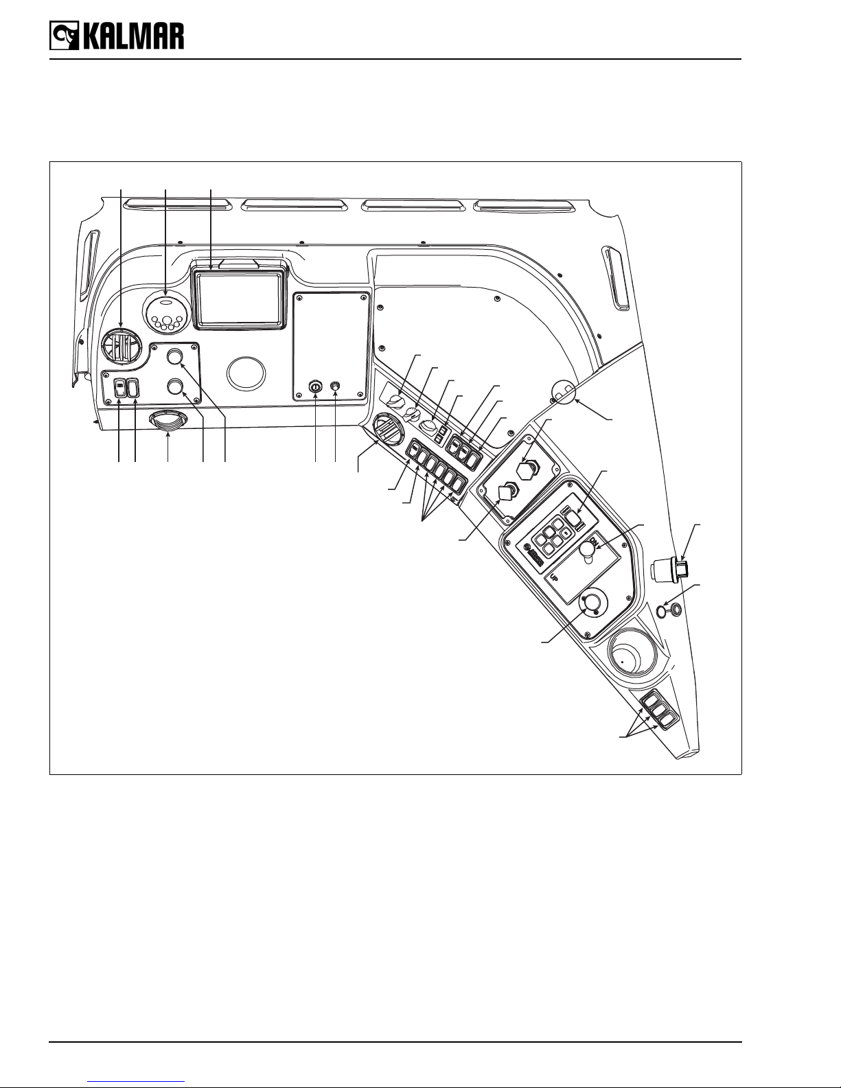
3.1.5 Instrument Panel Gauges, Controls and Indicators
Instrument Panel Overview
Figure 5
18

3 Description and Operation
S=Standard A=Assigned options
U=Unassigned options
POS Name
1 Air Diffuser S S
2 Radio A A
3 Main Gauge Panel S S
4 Headlight Switch S S
5 Dimmer Switch S A
6 Air Diffuser S S
7 Rear Wiper Switch A A
8 Front Wiper Switch S S
9 Ignition Switch S S
10 Push Button Start A A
11 Air Diffuser S S
12 Dome Light S S
13 Air Horn A A
14 Option Switches U U
15 Heater Control S S
16 Heater Control S S
17 Heater Control S S
18 Heater Control S S
19 Front Floodlight S S
20 Rear Floodlight S S
21 Trailer Air Supply S S
22 Parking Brake Control S S
23 Transmission Shifter S S
24 5th Wheel Control S S
25 5th Wheel Latch Control S S
26 Power Outlet A A
27 Option Switches U U
28 Air Restriction Indicator A A
29 Power Studs A A
Standard DOT/EPA
Tractor
Off-Highway Tractor
19

Figure 6
152 64 73
1 2 3
65 4
Left Dash Panel
3 Description and Operation
Left Dash Panel
1. Headlight Switch
Controls headlights and running lights on the tractor and
trailer. This switch also activates the interior dash and
gauge lights when either the headlights or the running lights
are on.
2. Dimmer Switch (optional)
Controls light level of dash panel controls.
3. Front Wiper Switch
Operates the front windshield wiper. Turning the control
clockwise increases the speed of the wiper. Turning the
control counterclockwise completely parks the wiper.
4. Rear Wiper Switch (optional)
Operates the rear windshield wiper. Turning the control
clockwise increases the speed of the wiper. Turning the
control counterclockwise completely parks the wiper.
5. Radio (optional)
Refer to the manufacturer's owner manual for features and
operating information.
6. Ignition Switch
Standard switch used to start the tractor. Refer to page 25
for more information.
7. Push Button Starter
Optional method to start the tractor. Refer to page 26 for
more information.
Main Gauge Panel
1. DEF Gauge
Indicates the level of diesel exhaust fluid in the tank in 1/4
increments. DOT/EPA Tractors Only.
Volt Meter
Indicates the status of the charging system in volts. If the
engine is running, the gauge indicates the alternator output
voltage. If the engine is not running, the voltmeter indicates
the output voltage of the battery. Off-Highway Tractors
Only.
2. Speedometer
Indicates vehicle speed in M.P.H. or K.P.H. This gauge may
also come with an odometer feature built in.
3. Fuel Gauge
Indicates the level of fuel in the fuel tank in 1/4 increments.
Figure 7
Main Gauge Panel
20
4. Rear Brake Air Pressure Gauge
Indicates air pressure in the rear air system in P.S.I.
5. Odometer and Hour Meter
Indicates vehicle distance traveled in miles and total hours
of operation.
6. Front Brake Air Pressure Gauge
Indicates air pressure in the front air system in P.S.I.

3 Description and Operation
LEFT CENTER RIGHT
ATC
ABS
ABS
1 2 3
456
Figure 8
Indicator Lights on the Main Gauge Panel
Tell Tale Indicator Lights
The indicator lights are located along the top of the main
gauge panel (Figure 8). The standard indicators are listed
below:
Left Side Indicator Lights
Figure 9
Left Side Indicator Lights
1. Left Turn Signal
Indicates left-hand turn signal is on when flashing.
2. Charger
Indicates the charging system is not functioning properly
and the battery power is low.
3. Water-in-fuel
Indicates water has been detected in the fuel system and
should be corrected.
4. ATC
Indicates the automatic traction control is operating.
5. Trailer ABS
Indicates the trailer anti-lock braking system is operating.
6. Tractor ABS
Indicates the tractor anti-lock braking system is operating.
21

7 8 9
CHECK
ENGINE
11 12 13
Figure 10
Center In dicator Lights
BRAKE
AIR
STOP
ENGINE
10
CHECK
TRANS
14
3 Description and Operation
Center Indicator Lights
7. Low DEF Level
Indicates the diesel exhaust fluid level is low and should be
filled. DOT/EPA Tractors Only.
Lamp function indicates the following status:
Low: First warning to the driver that the reducing agent is low.
The DEF lamp light will be solid.
Warning: Intermediate warning to the driver that a derate will
be activated if the reducing agent is not refilled. The DEF lamp
will start to flash.
Low Level Inducement: Second warning to the d river that th e
reducing agent is low and inducement derate will be activated
at this level. The DEF lamp will flash and the amber warning
lamp will be solid.
Severe Inducement: Once the DEF tank is empty and a key
cycle has occurred or after an extended idle operation, the
vehicle will be restricted to 5 M.P.H. and R.P.M. limit. The DEF
lamp will flash and the red lamp is solid.
8. High Beam
Indicates the high-beam lamps have been activated.
9. Brake Air
Alerts the driver that the brake system air pressure is
70 P.S.I. (4.83 bar) or lower.
10.Low Fuel
Indicates the fuel tank has 1/8 tank or less of fuel
remaining.
11. Malfunction Indicator Lamp (MIL)
Indicates the engine is malfunctioning and should be
checked. DOT/EPA Tractors Only.
12.Check Engine
Alerts the driver that the engine has an issue that requires
immediate attention. Shut the tractor down immediately
and have it serviced.
13.Stop Engine
Indicates a serious condition has occurred. Shut down the
tractor immediately and have it serviced.
14.Check Transmission
Alerts the driver to check the transmission/transmission
fluid level.
22

3 Description and Operation
1 2 3
8
9 10
657104
15 16 17
Right Side Indicator Lights
15.Wait to Start
Indicates the engine temperature is too cool to start the
engine immediately. Wait until the engine has been
properly heated before starting the engine.
WAIT TO
START
18 19 20
Figure 11
Right Indicator Lights
SERVICE
16.Seat Belt
Indicates the seat belt should be fastened.
17.Right Turn Signal
Indicates right-hand turn signal is on when flashing.
18.High Exhaust System Temperat ure
Indicates that high exhaust temperatures exist. Shut down
the engine and allow the exhaust system to cool before
restarting the engine. Refer to the Exhaust System section
for more information. DOT/EP A Tractors Only.
19.DPF (Diesel Particulate Filter) Regen Needed
Indicates the diesel particulate filter requires regeneration
within the next 2-6 hours of operation. Refer to the Exhaust
System section for more information. DOT/EPA Tractors
Only.
20.Service
Indicates the tractor requires immediate service.
Center Dash Panel
1. Fan Speed Control
Adjusts the fan speed. Rotate the dial clockwise to increase
the speed. Full counter-clockwise is the OFF position.
2. Mode Selector
Directs air flow to passenger compartment vents or to the
windshield for defrosting.
Figure 12
Center Dash Panel
3. Temperature Control
Controls the temperature of the air flowing into the cab. The
dial can be rotated between COLD (full counter-clockwise)
and HOT (full clockwise) to obtain the desired amount of
heat or cold air.
4. Air Recirculation Switch
Re-circulates air in the passenger compartment.
5. Air Conditioner Switch (Optional)
Activates the air conditioning compressor when the
optional air conditioning is installed.
6. Front Floodlights
Activates the floodlights at the front of the vehicle.
7. Rear Floodlight
Activates the floodlight at the rear of the vehicle.
8. Dome Light
Activates the interior light in the cab.
9. Air Horn
Activates the air horn.
10.Optional Switches
23

Figure 13
8
1 3 4 9
5
7
6
2
Right Dash Panel
3 Description and Operation
Right Dash Panel
1. Trailer Air Supply
Activates the trailer air supply. (See page 37, Parking
Brake and Trailer Air Supply Controls.)
2. Parking Brake Control
Operates the parking brakes on the vehicle and trailer.
(See page 37, Parking Brake.)
3. Transmission Shift Selector
Selects the operating range of the transmission. (See page
32, Transmission.)
4. Boom Control Lever
Operates the hydraulic boom and fifth wheel. (See page
40, Hydraulic Boom Operation.)
5. Fifth Wheel Unlatch Control
Engages the fifth wheel jaw locking mechanism. (See page
40, Fifth Wheel Unlatch Control Valve.)
6. Power Outlet
Cigar lighter port provides 12-volts of power.
7. Optional Switches
Figure 14
A — High Beam Switch
B — Turn Signal Lever
C — Emergency Flasher Switch
8. Power Studs
Provides positive and negativ e co nnecti on poi nts for CB
radio or other devices.
9. Air Restriction Indicator
Monitors resistance of airflow through the air cleaner
system. If a significant restriction arises, the indicator
button will pop up, indicating it is time to change the air
filter. Push the button back down to reset the indicator.
Turn Signal, High Beam and Emergency Flasher
Control
The column-mounted control on the Kalmar tractor has three
functions. It is located on the left-hand side of the steering
column (Figure 14).
1. Moving the lever (Figure 14, B) forward activates the right
turn signal. Moving the lever to the rear activates the left
turn signal. The turn signal is not self canceling and must
be returned to the center (OFF) position manually after it is
engaged. The green arrows on the dash panel light up and
flash when the switch is activated.
2. The button on the end of the lever operates the high beam
lights (Figure 14, A). The headlights must be on for the
switch to work. When the high beam headlights are on, the
high beam indicator on the dash will light up.
3. The pull out switch under the lever activates the emergency
flashers (Figure 14, C). Pulling out on the switch turns the
flashers on. To turn the flashers off, move the turn signal
lever forward or backward.
24

3 Description and Operation
NOTICE
Driver Controlled Differential Lock
(Optional on drive axles)
Drive axles may be equipped with a driver controlled
differential lock. This is a servo-controlled, air-actuated traction
device that can be manually controlled inside the cab by the
operator. By actuating a dash-mounted control, the operator
can lock or unlock the differential.
The differential must not be engaged when traveling at
higher speeds or down steep grades with limited traction.
앫 When the differential is fully locked, the vehicle will
have reduced steering capability. Do not use the
differential when driving at higher speeds or loss of
vehicle control, serious injury or death can result.
앫 The differential must not be engaged when traveling
down steep grades when traction is limited. This can
result in loss of vehicle control, damage to
components, serious injury or death. Refer to the axle
manufacturer for the correct operational and
maintenance procedures.
Figure 15
Driver Controlled Differential Lock
Ignition Switches
The standard ignition switch on the Kalmar tractor is a key
type, similar to the kind found on automobiles. Push button
and other types of ignition switches are installed as optional
equipment.
Key-Type Ignition
There are three positions: OFF, ACCESSORY and
RUN/START. The full left (counterclockwise) position is the
OFF position. The second position to the right (clockwise) is
the ACCESSORY position. The third position to the right
(clockwise) is the RUN/STAR T position.
The RUN/START position is used to engage the starter motor.
Moving the switch to the full right position engages the starter
and upon release of the key, the switch automatically stays in
the RUN position.
The ACCESSORY position activates the tractor’s electrical
accessory circuit.
The OFF position cuts all power to the electrical system and
shuts down the engine.
The OFF position on the standard three-position key-type
switch is designed to function as the engine stop. There is no
other engine stop device other than the ignition switch on the
standard Kalmar tractor.
25

3 Description and Operation
NOTICE
Push Button Starter
Push button starters are optional on Kalmar tractors. There are
two basic types of toggle ignition switches: three position and
two position.
The three-position type functions like the standard key type
with OFF, ACCESSORY and RUN positions. The button
engages the starter when the switch is in the RUN position
only .
The two-position switch has only the OFF and RUN positions.
It has no provision for the ACCESSORY position. The button
engages the starter in the RUN position only.
If the engine does not start within 30 seconds, release the
starter switch and wait 3 minutes to allow the starter
motor to cool. If after three repeated attempts the engine
still fails to start, stop and determine the cause. The
starter motor may be damaged by repeat ed attempts to
start the engine.
Some vehicles may be equipped with optional shut down
systems or optional starter switches. Contact your Kalmar
dealer if you have any questions regarding the operation of
any optional starter switches or shut down systems.
For starting the vehicle, refer to page 30, Starting the Engine.
3.1.6 Electrical Equipment
Accessory Connections
The wiring harness in the Kalmar tractor is designed to support
many vehicle options. These options may or may not already
be on your vehicle. If any electrical equipment is installed on
the vehicle after it leaves the factory, contact your Kalmar
dealer first. Your dealer can provide you with information on
proper electrical modifications and installations. Generally,
there will be an accessory location on the harness where you
will need it. Do not risk damaging your vehicle or voiding the
warranty by making improper and poor electrical modifications.
Contact your Kalmar dealer first.
Relays/Breakers/Fuses
26
The Kalmar tractor is equipped with two power boards. One
power board is located in the cab under the center panel of the
dash. The second power board is located in the chassis over
the transmission on the left side. See following figures for fuse,
breaker and relay locations.

3 Description and Operation
Figure 16
Cab Power Board
27

3 Description and Operation
Figure 17
Chassis Power Board
28

3 Description and Operation
NOTICE
3.1.9 Occupant Restraint
System
THE KALMAR TRACT OR IS E QU IPP ED WI TH S EAT BELTS.
THEY SHOULD BE USED WHENEVER THE VEHI CLE IS IN
OPERATION.
Seat Belt Operation
Always use seat belts whenever the vehicle is in
operation. In the event of a sudden stop or accident,
unbelted riders can be thrown about the cab or into the
windshield, resulting in serious injury or death.
The seat belt system used on Kalmar tractors is a lap-type
restraint with an automatic retractor.
Before fastening the seat belt, be sure to adjust the seat to a
comfortable driving position. T o fasten the belt, pull the belt low
across the hips and insert the tongue into the buckle.
T o release the seat belt, press the button on the buckle and the
belt will retract automatically.
3.2 Chassis
3.2.2 Powertrain
Engine
Kalmar tractors come equipped with a variety of engines.
Kalmar provides the manufacturer’s Engine Operation Manual
with each vehicle.
It is the operator’s responsibility to read the Engine
Operation Manual and follow all instructions provided by
the engine manufacturer. Failure to do so can result in
injury.
Engine performance is very important to the efficient operation
of the Kalmar tractor. Failure to properly maintain and operate
any engine can lead to very costly repairs and extensive down
time. KNOW YOUR ENGINE AND MAINTAIN IT!
This manual only contains basic information on engine
operation that applies specifically to the Kalmar tractor, or is
applicable to all diesel engines. For additional information,
contact the individual component manufacturer directly or via
the internet to obtain manuals.
29

3 Description and Operation
NOTICE
If you did not receive an Engine Operation Manual,
contact your Kalmar dealer.
Failure to read and follow the engine manufacturer’s
instructions regarding engine operation may lead to
severe engine damage. Read the Engine Oper atio n
Manual before operating this vehicle.
Starting the Engine
Never attempt to start the vehicle from any position other
than the driver’s seat. Attempting to start the vehicle while
standing, out side of the cab, or in the engine compartme nt
may cause the vehicle to move uncontrolled and cause
serious injury or death.
Always set the parking brake and place the shifter in
neutral before attempting to start the engine. Failure to do
so may cause the vehicle to move suddenly and
unexpectedly when the starter is engaged. Serious injury
or death can result.
All Kalmar tractors are designed to start in NEUTRAL
ONLY. If the vehicle you are operating starts while it is in
gear, DO NOT OPERA TE THE VEHICLE. Shut the vehicle
down and have the neutral lock-out system repaired
before operating the vehicle.
The following is provided as gener al gui deline information.
Always follow all instructions provided in the manufacturer’s
Engine Operation Manual. Different makes and models of
engines have different operating characteristics and
requirements. There are some important guidelines to follow
when starting any Kalmar equipped with a diesel engine.
These are listed below.
To start a vehicle equipped with the standard electrical starting
system, follow these steps:
30
Starting Procedure
All Kalmar tractors are designed to start in NEUTRAL ONLY.
The starter should not operate if the vehicle is in any other
gear.
1. Set the parking brake.

3 Description and Operation
NOTICE
NOTICE
NOTICE
2. Place the transmission control in NEUTRAL.
3. Apply the service brakes using the foot-operated treadle
valve and hold the brakes in this position.
4. Turn the ignition switch to the OFF position (if your vehicle
is not equipped with an ignition-operated engine shut
down, then use the engine shut down button or control to
stop the engine).
5. Wait for the “Wait to Start” light on the dash to go out if the
vehicle is equipped with one.
6. Turn the key to the START position. When the engine
starts, release the key and allow the switch to remain in the
RUN position.
If the engine does not start within 30 seconds, release the
starter switch and wait 3 minutes to allow the starter motor to
cool. If after three repeated attempts, the engine still fails to
start, stop and determine the cause. The starter motor may
be damaged by repeated attempts to start the engine.
Engine Shut Down
Diesel engines generate large amounts of heat. Internal
engine parts on any diesel engine need to cool down before
the engine is shut off. The operator should allow the engine to
idle for at least 3 minutes prior to shutting the engine down.
This cool down period allows the coolant to dissipate internal
engine heat. Shutting a hot engine down without a cool down
period may cause an immediate and excessive increase in
engine temperature. This could severely damage internal
engine components.
Always refer to the Engine Operation Manual for complete
information on engine shut down procedures.
Shut Down Procedure
1. Place the transmission in NEUTRAL.
2. Set the parking brake.
3. Allow the engine to idle at low idle for at least 3 minutes.
4. Turn the ignition switch to the OFF position (if your vehicle
is not equipped with an ignition-operated engine shut
down, then use the engine shut down button or control to
stop the engine).
5. Make sure all electrical accessories and lights are off and
the vehicle is in NEUTRAL.
Failure to follow the engine manufacturer’s guidelines
regarding engine shut down procedures may cause severe
engine damage.
31

3 Description and Operation
Engine Oil
Always refer to the Engine Operation Manual for complete
information on engine oil requirements. Service intervals, oil
types and refill quantities are all covered in the Engine
Operation Manual. READ IT!
Transmission
Standard tractors are equipped with an Allison Automatic
Transmission. This heavy-duty transmission is designed for
stop-and-go operation. An Allison Transmission Operator’s
Manual is provided with every Kalmar tractor. This manual
provides important information on operation of the
transmission.
The following information can be found in your Allison
Operator’s Manual:
1. Gear selection
2. Shifting the transmission
3. Driving tips
4. Care and maintenance
5. Check oil level with shift er
6. Check/clear fault codes
7. Prognostics
The operator of this vehicle must read and follow the
instructions in the Allison Operator’s Manual. Failure to
do so may lead to serious vehicle damage or personal
injury.
The forward t o reverse shif ts of the tran smissi on are co ntrol led
by the ECM.
Parking with an Automatic Transmission
The Allison transmission does not have a PARK position like
an automobile transmission. For information on how to
properly park your Kalmar tractor, see the following sections in
this manual:
32
Page 37, Parking the Vehicle
Page 37, Parking Brake
Axles
Kalmar tractors may be ordered with a variety of axle
configurations, makes and models. It is important to refer to
the axle manufacturer’s information for your specific axle. You
can obtain axle operation and maintenance information from

3 Description and Operation
NOTICE
your local Kalmar dealer. The following is general axle
information and may not apply to your particular axle.
This manual does not contain complete operational
information on any axle. The operator must obtain and refer
to the axle manufacturer’s information on operation, service
and maintenance.
Axle Operating Temperature
Normally, axle operating temperatures will not exceed more
than 100°F (37°C) above ambient temperature. Operating
temperatures above 230°F (110°C) significantly increase the
rate of lubricant oxidation and shorten the effective life of the
lubricant. This makes more frequent changes necessary.
Rear Axles with Locking Differentials
Kalmar tractors may be equipped with a variety of special axle
and differential combinations. Because of the affect of special
differentials on vehicle operation, it is important to understand
how your particular differential operates. Locking or limited slip
differentials are not standard on Kalmar tractors. If you do not
know if your vehicle is equipped with a special axle and
differential, contact your Kalmar dealer.
“No Spin” Positive Locking Differential
Kalmar tractors may be equipped with an optional “No Spin”
differential. This locking differential has very special operating
characteristics. IT IS VERY IMPORTANT FOR THE
OPERATOR OF A VEHICLE EQUIPPED WITH THIS
FEATURE TO OBTAIN AND FOLLOW ALL OF THE
OPERATION AND MAINTENANCE INFORMATION
PROVIDED BY THE DIFFERENTIAL MANUFACTURER.
Contact your Kalmar dealer for assistance on operating and
maintaining this differential.
3.2.4 Air System and Brakes
Brakes must be kept in proper working condition.
Operating a vehicle with poorly maintained brakes or worn
out brakes can cause a loss of vehicle control. This may
lead to serious injury or death. Never operate the vehicle
unless the brakes are working properly.
Do not allow moisture to collect in the air tanks. The air
tanks must be drained daily. Failure to drain the air tanks
can damage the air brake system and lead to injury.
33

Figure 18
B A
A — Accelerator Pedal
B — Brake Treadle/Pedal
3 Description and Operation
Kalmar tractors come equipped with a pneumatic (air) brake
system. This system has two basic parts: the service brakes
and the spring parking brakes.
The service brakes are the part of the system that the driver
uses when he operates the foot-operated treadle valve (or foot
pedal) in the cab (Figure 18).
The service brakes are the primary brakes used by the
operator. The service brakes require air to operate. If there is
insufficient air in the system, the se rvic e br ake s will not
operate.
The spring brakes are used for parking the vehicle. They are
also called the parking brakes because the parking brake
control applies the spring brakes. The spring brakes use the
mechanical force of a spring to operate. They do not need air
to operate, but they do need air to be released. If there is a
loss of pressure in the system, these brakes will automatically
apply. This is why the spring brakes are sometimes called
“emergency” brakes. Remember, if there is no air in the
system, the spring (parking) brakes will not fully release.
Low Air Pressure Indicators
When air pressure in the brake system is below 70 P.S.I.
(4.83 bar), the warning buzzer will sound and the Low Air
warning indicator on the dash panel will li ght up. The air
pressure gauge should indicate low air pressure in the system.
The warning buzzer will shut off after air pressure has reached
70 P.S.I. (4.83 bar) (see page 22).
If the warning light and buzzer do not shut off at least
5 minutes after start-up, shut the engine down and determine
why the air system is not charging.
If the Low Air indicator light or buzzer indicates a loss of air
pressure while driving, the vehicle should be stopped
immediately. The vehicle should not be operated until the air
system is repaired and functioning prope rly.
Do not operate the vehicle if the air brake system is not
working properly. If the air brakes are not working
properly, have the vehicle repaired immediately by a
qualified technician. Operating a vehicle when the air
brake system is not working properly can result in serious
injury or death.
34

3 Description and Operation
Service Brakes
The service brake system is controlled by a foot-operated
treadle valve (foot pedal) in the cab. This is the left-hand pedal,
located to the right of the steering column (Figure 18). The
amount of foot pedal pressure determines the amount of air
pressure delivered to the brakes. The more pressure applied
on the treadle valve (pedal), the more braking force is applied
to the brakes. The service brakes should be applied in a
smooth, constant application. They should not be pumped or
fanned while slowing or stopping the vehicle. Even in an
emergency stop situation, the service brakes should not be
rapidly “pumped”.
Do not pump the air brakes like a car during an emergency
stop. Rapidly pumping the brakes is more likely to use up
all of the air in the system and cause the spring brakes to
apply and lock the rear wheels. This can result in an out of
control skid, serious injury or death.
While the engine is running, the air compressor replenishes
the brake system air supply. This air supply provides the
pressure necessary to operate the service brakes.
The service brakes require at least 70 P.S .I. (4.83 bar ) to
operate effectively. If the system is not up to at least 70 P.S.I.
(4.83 bar), there may not be enough air in the system to stop
the vehicle. Several hard brake applications can quickly
deplete the pressure in the air system and could possibly
cause the pressure to drop below 43 P.S.I. (2.96 bar). If this
happens, the spring brakes will apply automatically, possibly
causing the operator to lose control of the vehicle.
The service brake system is integrated with the parking brake
system. Should the service brake system fail because of a lack
of air pressure (below 43 P.S.I. [2.96 bar]), the spring brakes
will automatically be applie d for emerg enc y braking .
Rapid successive brake application and release,
sometimes referred to as “fanning” or “pumping” the
brakes, should be avoided. This is an improper way to
slow or stop a vehicle with air brakes and may use up all
of the air in the system before the vehicle is stopped or
slowed completely. This could result in serious injury or
death.
35

3 Description and Operation
Always connect both trailer air lines when towing a trailer.
Failure to connect both the trailer service (BLUE), and the
trailer supply (RED) air lines greatly reduces braking
ability of the tractor trailer combination and creates a
serious hazard. This increases the possibility of an
accident and could result in serious injury or death.
Never operate the vehicle when system air pressure is
below 70 P.S.I. (4.83 bar). There may not be enough air in
the system to stop or slow the vehicle. Have the brake
system checked by a certified air brake mechanic if there
is any doubt about the brake system pe rformanc e. Fa ilure
to ensure sufficient air pressure can result in serious
injury or death.
ABS
Some trucks may be equipped with the Anti-lock Braking
System (ABS). The ABS is designed to prevent wheel lockup
during hard braking.
Trucks equipped with ABS have an indicator light located in
dash panel 1. The indicator light will warn the operator if there
is a potential problem in the system.
Trucks should not be operated if the indicator light is on.
Contact your nearest Kalmar dealer for qualified service on the
ABS.
Trucks built with ABS after March of 2002 have the capability
to check the trailer for a properly operating system. After
connecting a trailer to the truck, the system will run a
diagnostics check. If a problem is detected with the trailer side
of the ABS, a trailer warning indicator light on the dash will
illuminate.
Traction Control
Automatic traction control (ATC) is available as an option on
trucks equipped with the Anti-lock Braking System. When
activated, the ATC active/warning lamp will be on and the
system will limit wheel spin during hard acceleration. The
system is activated by turning on the ATC enable/disable
switch located on the dash. During activation, the warning
lamp will blink to advise the driver that drive-wheel spin is
occurring.
36
ATC can be disabled while the vehicle is stationary or in
motion. However, ATC will not re-enable until the vehicle
comes to a complete stop, even with the switch turned to the
ENABLE position.

3 Description and Operation
NOTICE
Never operate the vehicle if the truck or trailer ABS
warning (indicator) lights remain illuminated. This
indicates the ABS is not functioning properly. Shut the
vehicle down and have the ABS repaired immediately.
Operating a vehicle without a properly operating ABS can
result in loss of vehicle control, personal injury or death.
Parking Brake
Kalmar tractors are equipped with spring brakes for parking.
The parking system is operated manually by a cab-mounted
parking brake control valve (Figure 19). (Also see page 21,
items 5 and 6.)
The purpose of the parking (spring) brakes is to hold the
vehicle while in the PARK position.
Never apply the parking brake during normal driving.
Doing this will lock the rear wheels, possibly causing an
uncontrolled stop.
Parking Brake and T railer Air Supply
Controls
Air pressure in the system must be at least 70 P.S.I. (4.83 bar)
before the parking brake control or the trailer air supply control
can be pushed in (releasing the spring brakes).
If the tractor air system is completely discharged, the trailer
parking brake control will be applied. The trailer parking brake
should not be released until the tractor brakes are rolling.
Parking the Vehicle
(Refer to Transmission on page 32 and Parking Brake above
for additional information.)
Standard Kalmar tractors are equipped with an Allison
automatic transmission and spring-operated parking brakes.
Allison transmissions are unlike an automobile transmission in
one important regard. They do not have a PARK position.
Figure 19
Parking Brake and Trailer Air Supply Controls
When parking your Kalmar tractor, there are some important
rules that must be followed.
37

3 Description and Operation
NOTICE
Failure to observe the following rules when parking the
vehicle may lead to death or serious injury.
1. Always apply the parking brake.
2. Never park the vehicle by leaving it in gear. Always
place the transmission shifter selector in the “Neutral”
position.
3. Never park a tractor trailer combination unless the
trailer parking brakes are operational and applied.
If the vehicle is parked in gear, the vehicle will not start.
Manually Releasing Tractor Spring
Brakes (Caging)
When air pressure in the system drops below approximately
43 P.S.I. (2.96 bar), the spring parking brakes will apply
automatically. To release the spring brakes, the air pressure
must be returned to 70 P.S.I. (4.83 bar). If the system cannot
be recharged and the vehicle must be moved, the spring
parking brakes can be released manually (caged).
Figure 20
Internal Caging Tool
To release the spring brakes, the actual spring in the brake
canisters must be mechanically compressed. A release stud,
or spring caging tool, must be used to manually compress the
brake chamber.
Never manually release (cage) the spring brakes before
the wheels are properly blocked. If the wheels are not
properly blocked before releasing the spring brakes, the
vehicle may move unexpectedly. This could result in
serious injury or death.
The following steps can be used to release the standard brake
chambers used on most Kalmar tractors. If your vehicle is
equipped with other optional brake chambers, refer to that
manufacturer’s operation or service manual.
1. Shut the engine off and remove the key.
2. BLOCK ALL wheels front and rear to prevent the vehicle
from rolling forward and backward.
3. Determine whether the chamber has an internal (Figure 20)
or external (Figure 21) caging tool. Proceed to step 4 with
an external-mounted tool. See step 8 for internal types.
4. Remove the access plug from the brake canister.
5. Insert the caging tool into the access hole, “T” end first.
38

3 Description and Operation
NOTICE
Figure 21
External Caging Tool
6. Turn the caging tool 1/4 turn to engage with the slot on the
pressure plate.
7. Try to pull the caging tool out; it should not pull out. If it
does, repeat steps 5 and 6.
8. Thread the nut and washer down onto the threaded end of
the caging tool all the way to the canister.
9. Tighten the nut until the threaded portion of the release tool
is out. It should extend approximately 3 inches (76.2 mm)
out of the nut.
3 inches (76.2 mm) — Type 2430 and 3030 Chambers
4 inches (101.6 mm) — Type 3036 and 3636 Chambers
Never use an impact wrench to tighten the nut onto the
release bolt. Never exceed the above lengths and never
exceed 50 ft. lbs. (67.79 N•m) of torque on the release nut or
the chamber may be damaged.
Trailer Brakes
Kalmar tractors are designed to use the trailer’s brakes when
towing trailers. All Kalmar tractors are equipped with a trailer
Supply air line and trailer Service air line. The service line is
BLUE. The supply line is RED.
When the vehicle is towing a trailer and service and supply
lines are connected to the trailer, the trailer brakes become
part of the tractor’s brake system. The tractor service brakes
control the trailer service brakes. The tractor parking brake
control operates the tractor and trailer spring brakes. This is
why it is critical that the operator always connect both air lines
to the trailer.
Trailer Air Lines
The service air line (blue hose) operates the trailer service
brakes. The supply air line (red hose) only supplies air to the
trailer spring brakes to release them. If only the supply air line
is attached to the trailer, the trailer service brakes will not
operate. The tractor service brakes will be doing all the braking
for the combination and braking distances will be dramatically
increased. Without the trailer service brakes working, jackknifing and loss of vehicle control is much more likely during
heavy braking.
Always connect both trailer air lines when towing a trailer.
Failure to connect both the trailer service (BLUE), and the
trailer supply (RED) air lines greatly reduces braking
ability of the tractor trailer combination and creates a
serious hazard. This increases the possibility of an
accident and could result in serious injury or death.
39

3 Description and Operation
B
A
3.2.5 Hydraulic System
Hydraulic Fifth Wheel Lifting System
The standard fifth wheel lifting system on Kalma r tract or s is
hydraulically operated. A P.T.O. and hydraulic pump mounted
on the transmission provide the hydraulic power to operate the
Hydraulic Fifth Wheel Lifting System. The fifth wheel is
mounted to a hydraulically operated “Boom” (Figure 22). This
“Boom” assembly is attached to the frame at a pivot behind the
cab. The system operates like a large hydraulic floor jack.
The following are general operating instructions and may not
apply to your particular vehicle. If there are any questions
regarding the operation of your vehicle or a particular option,
contact your Kalmar dealer.
Hydraulic Boom Operation
The hydraulically operated boom is controlled by a lever inside
the cab. The lever is located on the console to the right of the
seat and next to the shift lever (page 24).
Figure 22
A — Fifth Wheel Plate
B — Boom
Never raise or lower the boom while the tractor and trailer
combination is moving. Raising the boom while the
tractor and trailer are moving creates a “rollover” hazard
and may cause the vehicle to rollover possibly resulting in
serious injury or death. DO NOT OPERATE THE BOOM
CONTROL LEVER WHILE THE VEHICLE IS MOVING A
TRAILER.
T o Raise the Fifth Wheel: To raise the boom, the engine must
be running. Pushing the lever to the UP position indicated on
the boom operating lever, raises the fifth wheel. To increase
the rate of travel of the boom, the engine may be idled higher
while the vehicle is in NEUTRAL ONLY.
To Lower the Fifth Wheel: To lower the boom, the engine
must be running and the transmission in NEUTRAL. Pulling
the boom control lever to the DOWN position marked on the
boom operating lever, lowers the boom and fifth wheel. To
increase the rate of travel of the boom, the engine may be
idled higher while the vehicle is in NEUTRAL ONLY. Standard
configuration of the boom allows both power up and down
capability.
Fifth Wheel Unlatch Control Valve
The Kalmar tractor comes standard with an air-operated fifth
wheel unlatch cylinder. The cylinder is operated by a “pushtype” valve located on the right-hand console behind the shifter
(page 24). Pressing the fifth wheel unlatch valve opens the
kingpin jaws in the fifth wheel. After the jaws are opened, they
remain open until the fifth wheel is connected to a trailer
kingpin.
40

3 Description and Operation
NOTICE
NOTICE
When pulling out from under a trailer, the control must be
depressed and held until the fifth wheel is clear of the trailer
kingpin.
Basic Trailer Spotting Steps
The following information is for reference only. Kalmar
Solutions, LLC highly recommends using the following
information to create procedures that match your particular
application and vehicle. It is the operator’s responsibility to
ensure that proper trailer moving procedures are used for a
particular situation and vehicle application.
1. Maintain optimum tractor air pressure (120 P.S.I.). The fifth
wheel should be in the FULL DOWN position. Be
absolutely positive that the fifth wheel jaws are in the
UNLATCH position by depressing the unlatch control valve
located to the right of the shifter. (See page 24.)
2. Line the tractor up to the front of the trailer by centering the
fifth wheel to the center line of the trailer. Make sure that
the tail of the fifth wheel is BELOW the trailer skid ramp.
3. Back the tractor UNDER the trailer until the ENTIRE fifth
wheel DISAPPEARS UNDER the front edge of the trailer
floor/skid plate.
4. With your foot firmly on the brake treadle and the tractor
shift lever in NEUTRAL, move the boom control lever to the
UP position and raise the trailer until the trailer support is
JUST OFF THE GROUND. DO NOT raise the trailer any
more than a few inches to provide clearance between the
trailer landing gear and the ground at this step.
5. After you have obtained adequate ground clearance at the
trailer landing gear, place the shift selector in REVERSE,
release your foot from the brake treadle and back FIRMLY
into the kingpin jaws until you feel full engagement.
REMEMBER, the latching jaws in the fifth wheel MUST BE
FULLY IN THE OPEN POSITION BEFORE attempting
kingpin engagement.
6. Place the transmission shift lever into a forward drive gear
and give a “TUG” at the kingpin to ensure positive lock of
the jaws around the kingpin. BE PREPARED to stop if the
fifth wheel jaws have not fully latched to avoid pulling out
from under the trailer and dropping it.
7. Place the shift lever in the NEUTRAL position and raise the
boom using the boom control lever. Raise the fifth wheel to
the necessary height to maintain ground clearance while
towing the trailer to the new location. Be aware of potential
overhead damage to a trailer if it is raised too high.
8. Once proper trailer height is reached, apply the tractor
parking brake. Now hook BOTH the trailer emergency and
service air lines to the trailer (blue and red air lines) and
plug in the trailer electrical cable.
41

3 Description and Operation
9. With the brake treadle FULLY applied, push in BOTH the
parking brake control (yellow) and the tra iler air suppl y
(red). This will charge the trailer air supply and release the
trailer spring/parking brak es.
10.After the tractor air system is fully charged, move the
transmission shift lever to the proper gear and release
pressure on the foot-operated brake treadle. Allow the
vehicle to roll a VERY SHORT distance and then depress
the brake treadle again to stop the vehicle. This procedure
will ensure that the service brakes on the trailer are working
properly. NOW, and ONLY NOW, are you ready to move
(“SPOT”) the trailer.
11.Once the trailer is relocated and the vehicle combination is
completely stopped, place the shift lever in NEUTRAL and
pull out on the trailer air supply control (red). This will apply
the trailer parki ng brakes only. The parking brake control
(yellow) should remain “in” with the tractor parking brake
released.
12.Using the boom control lever, lower the trailer until the
trailer supports are resting completely on the ground.
13.Disconnect and STORE the air lines and electrical cable.
14.DEPRESS and HOLD the fifth wheel unlatch control valve
as you slowly pull away from the trailer. Once the fifth
wheel is completely clear of the kingpin, release the fifth
wheel unlatch control and go to the next trailer.
FAILURE TO READ AND FOLLOW ANY OF THE
FOLLOWING WARNINGS MAY LEAD TO SERIOUS INJURY
OR DEATH.
When the vehicle is operated on public streets or
highways, the fifth wh eel manual secondary lock MUST be
engaged and the fifth wheel MUST be in the DOWN
position.
NEVER raise or lower the boom while the vehicle has a
trailer attached and is in motion.
42
DO NOT EXCEED 15 M.P.H. (24 K.P.H.) WHEN TOWING
TRAILERS. Operating at speeds in excess of 15 M.P.H.
(24 K.P.H.) may lead to loss of vehicle control. NEVER take
turns at excessive speeds, as this may cause the vehicle
to roll over. The majority of all rollover accidents are
caused by excessive cornering speed. ALWAYS SLOW
DOWN WHEN CORNERING.

3 Description and Operation
Never tow trailers without BOTH the service and
emergency brake lines connected to the trailer. Never tow
trailers without functioning service and emergency brake
systems. Operating the vehicle while towing trailers
without functioning trailer brake systems may lead to loss
of control of the vehicle, serious injury or death.
Never tow a trailer above the minimum height required to
clear the landing gear from the ground. Lifting the fifth
wheel and trailer too high drastically raises the center of
gravity of the trailer and increases the chance of a rollover.
3.2.7 Exhaust System —
DOT/EPA-Approved Engines
Figure 23
High Exhaust Temperature Lamp
Exhaust system components can become extremely hot
from engine operation. Wait for the exhaust system to
cool down completely before performing exhaust system
service. Wear protective gloves when working around
exhaust system components. Failure to do so can result
in serious personal injury.
Diesel Particulate Filter (DPF)
Regeneration
T o meet current emissions regulations, this vehicle is equipped
with a Diesel Particulate Filter as part of its exhaust
aftertreatment system. The DPF traps diesel particulates and
requires periodic service to ensure its proper functionality.
Servicing involves regeneration (burning) of the trapped
particulates. The engine's ECM senses when regeneration is
required and can automatically, under the correct conditions,
initiate regeneration. If the correct conditions cannot be met,
the operator must initiate a "Stationary" regeneration. Not
performing a "Stationary" regeneration, when required, will
necessitate the removal of the DPF for service.
High Exhaust Temperature Lamp
The "High Exhaust Temperature" lamp illuminates to indicate
that high exhaust temperatures exist. When this lamp is
illuminated, the engine should be stopped and the exhaust
system allowed to cool before restarting the engine.
43

3 Description and Operation
NOTICE
START
REGEN
DPF (Diesel Particulate Filter) Regen
Needed Lamp
The "DPF Regen Needed" lamp indicates, when illuminated or
flashing, that the diesel particulate filter requires regeneration.
Figure 24
DPF Regen Needed Lamp
When the "DPF Regen Needed" lamp illuminates, the diesel
particulate filter needs to regenerate within the next 2-6 hours
of operation. This is accomplished by:
1. Changing to a more challenging duty cycle, such as
highway driving or similar, for at least 20 minutes,
OR
2. Performing a "Stationary" Regeneration.
If a regeneration is not completed in a timely manner after the
"DPF Regen Needed" lamp illuminates, the lamp will begin to
flash. When this happens, the actions on page 43 should be
performed within 1-2 hours. In addition, engine power may be
reduced automatically.
Performing a "Stationary" Regeneration
1. Park the vehicle in an area where it can safely idle for up to
50 minutes. The regeneration period may be from 5 to 50
minutes, depending upon severity.
2. Set the parking brake and let the truck idle.
3. Turn the Regen switch to the "ON" position. The switch is
located on the dash, to the right of the steering column.
Figure 25
Regen Switch
4. Do not throttle the engine or apply the brake pedal until the
regeneration is complete and the DPF light goes out.
Throttling the engine and/or applying the brake will stop the
regeneration process.
5. Turn the Regen switch to the "OFF" position after
regeneration is complete.
Check and Stop Engine Lamps
A flashing "DPF Regen Needed" lamp combined with an
illuminated "Check Engine" lamp indicates that the Diesel
Particulate Filter needs to be regenerated immediately. Engine
power will be reduced automatically. A "Stationary"
regeneration is required imm edi ate ly.
If a "Stationary" regeneration is not performed, the red "Stop
Engine" lamp will illuminate. The vehicle should be stopped
as soon as it can safely be done and remain shut down until it
can be serviced by an auth orized repair locati on.
Driver Tips
앫 The electric-actuated variable geometry turbocharger
causes the engine sound to vary at times. This is normal. A
slight turbo whistle may also be observed at idle conditions.
44

3 Description and Operation
CHECK
ENGINE
STOP
ENGINE
CHECK
ENGINE
Figure 26
Malfunction Indicator Lamp
앫 After prolonged idle, you may notice momentary white vapor
and odor. This is normal.
앫 Use only Ultra Low Sulfur Diesel (ULSD) fuel.
앫 Oil classification CJ-4 (low ash) is the recommended oil.
This will increase the time between regeneration events.
Exhaust-Related Engine Indicator
Lamps
Malfunction Indicator Lamp
The MIL illuminates when the On-Board Diagnostics system
detects a malfunction related to the emissions control system.
The illuminated MIL indicates that the engine and
aftertreatment system should be diagnosed and serviced at
your next available opportunity.
Diesel Exhaust Fluid (DEF) Lamp
Illuminated
Figure 27
Diesel Exhaust Fluid (DEF) Lamp
Figure 28
Diesel Exhaust Fluid (DEF) Lamp
Figure 29
Lamp Combination
Figure 30
Lamp Combination
An illuminated DEF lamp is an indication that the DEF level is
low. This can be corrected by refilling the DEF tank.
Flashing
A flashing DEF lamp indicates that the DEF level has fallen
below a critical level. This can be corrected by refilling the DEF
tank.
Flashing with Warning or Check Engine
Lamp
A flashing DEF lamp combined with an illuminated Warning or
Check Engine lamp indicates that the DEF level is critically low
and you will experience a power loss. Normal engine power
will be restored after refilling the DEF tank.
Stop Engine Lamp with Flashing DEF and
Warning or Check Engine Lamp
If the engine has been shut down or has idled for one hour
after the DEF tank has been run dry, the Stop Engine Lamp will
also be illuminated along with the flashing DEF lamp and
illuminated Warning or Check Engine lamp. Engine power will
continue to be reduced automatically. The vehicle will also be
limited to 5 M.P.H. (8 K.P.H.). Normal engine power and
vehicle speed will be restored after refilling the DEF tank.
45

Figure 31
STOP
ENGINE
DPF Regen Needed Lamp
Figure 32
DPF Regen Needed Lamp
CHECK
ENGINE
Figure 33
Lamp Combination
3 Description and Operation
Illuminated
An illuminated DPF Regen Needed Lamp is an indication that
the truck needs to perform a regeneration.
Flashing
If a regeneration is not performed in a timely manner after the
DEF lamp is illuminated, the DEF lamp will begin to flash. This
indicates a higher level of soot in the DPF. In addition engine
power may be reduced automatically.
Flashing with Warning or Check Engine
Lamp
A flashing DPF lamp combined with an illuminated Warning or
Check Engine Lamp indicates that the Aftertreatment DPF
needs regeneration immediately. Engine power will be reduced
automatically. Parked regeneration is required.
Figure 34
Stop Engine Lamp
Stop Engine Lamp
If Parked regeneration is not performed, the Stop Engine Lamp
will illuminate. The vehicle should be stopped as soon as it can
safely be done until it can be repaired.
46

6 Scheduled Maintenance
NOTICE
6 Scheduled Maintenance
6 Scheduled
Maintenance
General Maintenance
Program
One of the keys to safe and dependable operation of your
Kalmar tractor is proper maintenance. Yard tractors are used
in very abusive operations. Moving trailers through rough
yards 10 to 24 hours a day can take a toll on even the best
built piece of equipment. It is the operator’s job to ensure that
every time he or she climbs into the cab, that the vehicle is
ready to roll, safely and reliably.
Because all spotting applications are not the same, it is critical
that a good “T otal Maintenance Program” is developed for your
particular vehicle and application. A vehicle that runs 24 hours
a day in a railroad yard will need a more intensive
maintenance program than a vehicle running 8 hour days in a
smooth, paved lot.
If you need assistance on determining a good maintenance
program, call your Kalmar dealer for assistance.
The Kalmar Daily Inspection, or “walk around” will assist the
operator in identifying obvious problems that could affect
normal operation of the vehicle (a sample Daily Inspection
Form is provided on page 10). The daily inspection form is
not intended to be a substitute for a Preventative
Maintenance Program.
A vehicle that has not been properly maintained, may not
be safe to operate. The operator of a Kalmar tractor must
be satisfied that his/her vehicle has been properly
maintained and is in safe working condition, before
operating that vehicle. Operating an improperly
maintained vehicle may lead to loss of vehicle control,
which could severely injure or kill the operator.
Vehicle maintenance, other than routine operator
maintenance (checking fluids, cleaning, filling fuel tank),
should only be performed by a professional, trained
mechanic. Many maintenance procedures require special
training and tools to be done safely. Attempting to
perform maintenance procedures without proper training
and equipment may lead to serious injury or death.
47

6.1 Checklists
2
3
4
5
6
7
8
9
10
11
12
13
14
15
16
*
**
*
1
Chassis Lubrication Diagram
(left-hand drive chassis shown)
6 Scheduled Maintenance
Figure 35
Chassis Lubrication Diagram
*Both Sides
**Both Sides Front and Rear
48

6 Scheduled Maintenance
Key
No.
1 Coolant/Anti-Freeze 50/50 Ethyl-Glycol/Water
2 Engine Oil SAE 15W-40
3 Slack Adjusters Brake Cam
4 Front Axle King Pins Lithium Grease
5 Tie Rod Ends Lithium Grease
6 Transmission Fluid Transynd
7 Diesel Fuel ULSD
8 Universal Joints Lithium Grease
9 Rear Axle Differential EP 85-140
10 Driveline Slip Yoke Lithium Grease
11 Hydraulic/Steering Fluid Dexron III
12 Cab Suspension Latch Lithium Grease
13 Diesel Exhaust Fluid See Engine Operator Manual
14 Front Wheel Bearings EP Grade No. 1
15 Drag Link Ends Lithium Grease
16 Steering Slip Joint Lithium Grease
Part/Description Lubricant Used/Note
See Engine Operator Manual
Lithium Grease
Pivot
See Transmission Operator
Manual
See Engine Operator Manual
See Axle Operator Manual
See Axle Operator Manual
Boom and Fifth Wheel
Lubrication Diagram
Figure 36
Boom and Fifth Wheel Lubrication Diagram
*Both Sides
Key
No.
17 Boom Pivot Lithium Grease #1
18 Boom Cylinder Bearings Lithium Grease #1
19 Fifth Wheel Pivot Lithium Grease #1
20 Fifth Wheel Top Plate Lithium Grease #1
21 Fifth Wheel Jaws Lithium Grease #1
NI Cab Door Hinge Silicone Spray
NI Steering Column Slip Yoke Lithium Grease #1
NI Rear Door Rollers Silicone Spray
NI = Not Illustrated
Part/Description Lubricant Used/Note
49

6 Scheduled Maintenance
KALMAR TERMINAL TRACTOR PREVENTATIVE MAINTENANCE FORM
NON-SYNTHETIC (NON –TES-295) LUBE USED IN THE TRANSMISSION
√ = SATISFACTORY 0 = ADJUSTMENT NECESSARY Χ = REPAIRS NEEDED.
“A” INSPECTIONS SHOULD BE PERFORMED AT 250 HOUR INTERVALS, “B” INSPECTIONS AT 500 HOUR INTERVALS, “C” INSPECTIONS AT 1000 HOUR
Preventative Maintenance Form
TRUCK NUMBER LOCATION TECHNICIAN HOURS DATE
EACH OF THE FOLLOWING ITEMS SHOULD BE CHECKED AND THE CORRESPONDING BOX MARKED WITH THE APPROPRIATE NOTATION.
INTERVALS, AND “D” INSPECTIONS AT 2000 HOUR INTERVALS.
CAB – INTERIOR UNDER VEHICLE
CHECK OPERATION OF NEUTRAL START CHECK STEERING GEAR
CHECK OPERATION OF ALL GAUGES CHECK BRAKE LININGS AND DRUMS
CHECK LOW AIR BUZZER AND LIGHT CHECK SPRINGS
CHECK WINDSHIELD WIPER OPERATION CHECK SHOCK ABSORBERS (IF APP.)
CHECK WINDSHIELD WASHER OPERATION (IF APP.) TORQUE FRONT AXLE MOUNTING BOLTS
CHECK THROTTLE OPERATION TORQUE FRONT AXLE KING PIN DRAW KEY NUT(S)
CHECK HORN(S) OPERATION CHECK POWER STEERING PUMP
CHECK AIR SYSTEM – MINIMUM 120 PSI, MAXIMUM 130 PSI CHECK STARTER MOUNTING AND CONNECTIONS
CHECK AIR SYSTEM FOR LEAK DOWN CHECK ENGINE AND TRANSMISSION FOR LEAKS
CHECK OPERATION OF BACK UP ALARM CHANGE EN GINE OIL AND FILTER
CHECK HVAC SYSTEM CHANGE TRANSMISSION FILTERS
BLOWER MOTOR OPERATION CHANGE TRANSMISSION FLUID
TEMPERATURE CONTROL CHECK ENGINE AND TRANSMISSION MOUNTS
DEFROSTER OPERATION CHECK WHEEL SEALS FOR LEAKS
A/C OPERATION (IF APP.) CLEAN REAR AXLE BREATHER
AUXILIARY FAN(S) (IF APP.) CHECK DIFFERENTIAL FOR LEAKS
CHECK 5THWHEEL UNLATCH CONTRO L CHECK DIFFERENTIAL OIL LEVEL
CHECK OPERATION OF BOOM CHANGE DIFFERENTIAL OIL
CHECK OPERATION OF WINDOWS CHECK LIFT CYLINDERS FOR LEAKS
CHECK SEAT BELT SYSTEM PER 10-STEP INSPECTION TORQUE REAR AXLE MOUNTING BOLTS
CHECK OPERATION OF DOOR LATCHES
CHECK DOME LIGHT OPERATION CHECK FRONT WHEEL BEARINGS
CHECK ALL GLASS AND MIRRORS CHECK FRONT AXLE OIL LEVEL (IF APP.)
CHECK FIRE EXTINGUISHER CHARGE (IF APP.) REPACK FRONT WHEEL BEARINGS (IF APP.)
CAB DOWN – EXTERIOR
CHECK SIDE DOOR HINGE (IFF APP.) CHECK BATTERIES FOR CRACKS OR DAMAGE
CHECK CAB ACCESS STEPS AND HANDLES CLEAN BATTERY CABLE CONNECTIONS
CLEAN HEATER / AC FILTER (IF APP.) CHECK BATTERY BOX COVER HOLDDOWNS
CHECK REAR DOOR ROLLERS / SLIDE ADJUSTMENT DRAIN WATER FROM AIR TANKS
CHECK GLADHAND SEALS AND TRAILER AIR LINES CHECK AND TORQUE ALL WHEEL NUTS
CHECK TRAILER LIGHT CORD CHECK WHEELS
CHECK HEADLIGHTS / MARKER LIGHTS CHECK TIRE AIR PRESSURE, TREAD DEPTH & CONDITION
CHECK TURN SIGNALS CHECK REAR AXLE PLANETARY FLUID LEVEL (IF APP.)
CHECK STROBE LIGHT (IF APP.) INSPECT PLATFORMS
CHECK SPOTLIGHTS CHECK FRAME FOR CRACKS
CHECK WIPER BLADES CHECK MUD FLAPS / FENDERS (IF APP.)
CHECK WINDSHIELD WASHER FLUID LEVEL CHANGE HYDRAULIC SYSTEM FILTER
CHECK TRANSMISSION FLUID LEVEL CHECK HYDRAULIC FLUID LEVEL
CHECK ENGINE OIL LEVEL CHANGE HYDRAULIC FLUID
CAB UP
CHECK OPERATION OF CAB TILT PUMP CHECK CAB HINGE PINS AND BUSHINGS
CHECK CAB SAFETY PROP
CHECK CAB SUSPENSION AND LATCH CHECK / LUBRICATE REAR DOOR ROLLERS
CHECK INTAKE DUCTING FOR LEAKS CHECK / LUBRICATE STEERING SLIP JOINT
CHECK RADIATOR FOR LEAKS CHECK / LUBRICATE STEERING U-JOINTS
CHECK RADIATOR MOUNTS CHECK / LUBRICATE ALL STEERING LUBE POINTS
CHECK COOLANT LEVEL AND CONCENTRATION CHECK / LUBRICATE SLACK AD JUSTERS
CHECK AND AD J U S T CO OLANT ADD ITIVE (IF APP .) CHECK / LUBRICATE DRIVELINE U-JOINTS
CHANGE ENGINE COOLANT CLEAN, CHECK, ADJUST AND LUBE 5THWHEEL JAWS
CHECK COOLANT HOSES AND CLAMPS CHECK AND LUBRICA TE 5THWHEEL TOP PLATE
CHECK FAN CLUTCH FOR OPERATION (IF APP.) CHEC K AND LUBRICATE 5THWHEEL PIVOT PINS
CHECK ENGINE COOLING FAN FOR CRACKS CHECK AND LUBRICATE BOOM PIVOT BEARINGS
CHECK ENGINE BELT(S) AND TENSIONER CHECK AND LUBE BOOM CYLINDER BEARING
CHANGE ENGINE COOLANT FILTER (IF APP.) ADD GR EASE TO AUT O L UBE RESER V O IR ( IF APP .)
CHECK ENGINE AND TRANSMISSION FOR LEAKS
DRAIN FUEL WATER SEPARATOR DRIVE VEHICLE TO CHECK FOR OVERALL OPERATION
CHANGE FUEL F ILTER / FUEL WATER SEPARATOR
CHECK AIR RESTRICTION GAUGE (IF APP.)
CHANGE AIR FILTER AS NEEDED
CHANGE AIR DRYER DESICCANT (IF APP.) AS NEEDED
CHECK EXHAUST SYSTEM
CLEAN TRANSMISSION BREATHER
OPERATION A B C D OPERATION A B C D
CHASSIS
CHECK BATTERY CABLES & HOLDDOWNS
CLEAN HYDRAULIC TANK VENT
LUBRICATION
TEST DRIVE
50

6 Scheduled Maintenance
KALMAR TERMINAL TRACTOR PRE V ENTATIVE MAINTENANCE FO RM
SYNTHETIC (TES-295) LUBE AND ALLISON HIGH-CAPACITY FILTERS USED IN THE TRANSMISSION
√ = SATISFACTORY 0 = ADJUSTMENT NECESSARY Χ = REPAIRS NEEDED.
“A” INSPECTIONS SHOULD BE PERFORMED AT 250 HOUR INTERVALS, “B” INSPECTIONS AT 50 0 HOUR INTERVALS, “C” INSPECTIONS AT 1000 HOUR
TRUCK NUMBER LOCATION TECHNICIAN HOURS DATE
EACH OF THE FOLLOWING ITEMS SHOULD BE CHECKED AND THE CORRESPONDING BOX MARKED WITH THE APPROPRIATE NOTATION.
INTERVALS, AND “D” INSPECTIONS AT 2000 HOUR INTERVALS.
CAB – INTERIOR UNDER VEHICLE
CHECK OPERATION OF NEUT RAL START CH ECK STEERING GEAR
CHECK OPERATION OF ALL GAUGES CHECK BRAKE LININGS AND DRUMS
CHECK LOW AIR BUZZER AND LIGHT CHECK SPRINGS
CHECK WINDSHIELD WIPER OPERATION CHECK SHOCK ABSORBERS (IF APP.)
CHECK WINDSHIELD WASHER OPERATION (IF APP.) TORQUE FRONT AXLE MOUNTING BOLTS
CHECK THROTTLE OPERATION TORQUE FRONT AXLE KING PIN DRAW KEY NUT(S)
CHECK HORN(S) OPERATION CHECK POWER STEERING PUMP
CHECK AIR SYSTEM – MINIMUM 120 PSI, MAXIMUM 130 PSI CHECK STARTER MOUNTING AND CONNECTIONS
CHECK AIR SYSTEM FOR LEAK DOWN CHECK ENGINE AND TRANSMISSION FOR LEAKS
CHECK OPERATION OF BACK UP ALAR M CHANGE ENGINE OIL AND FILTER
CHECK HVAC SYSTEM CHANGE TRANSMISSION FILT ERS 3000 HOURS
BLOWER MOTOR OPERATION CHAN GE TRANSMISSION FLUID 6000 HOURS
TEMPERATURE CONTROL CHECK ENGINE AND TRANSMISSION MOUNTS
DEFROSTER OPERATION CHECK WHEEL SEALS FOR LEAKS
A/C OPERATION (IF APP.) CLEAN REAR AXLE BREATHER
AUXILIARY FAN(S) (IF APP.) CHECK DIFFERENTIAL FOR LEAKS
CHECK 5THWHEEL UNLATCH CONTROL CHECK DIFFERENTIAL OIL LEVEL
CHECK OPERATION OF BOOM CHANGE DIFFERENTIAL OIL
CHECK OPERATION OF WINDOWS CHECK LIFT CYLINDERS FOR LEAKS
CHECK SEAT BELT SYSTEM PER 10-STEP INSPECTION TORQUE REAR AXLE MOUNTING BOLTS
CHECK OPERATION OF DOOR LATCHES
CHECK DOME LIGHT OPERATION CHECK FRONT WHEEL BEARINGS
CHECK ALL GLASS AND MIRRORS CHECK FRONT AX LE O IL LEV E L ( IF APP.)
CHECK FIRE EXTINGUISHER CHARGE (IF APP.) REPACK FRO N T WH E EL BEARIN GS ( IF AP P . )
CAB DOWN – EXTERIOR
CHECK SIDE DOOR HINGE (IFF APP.) CHECK BATTERIES FOR CRACKS OR DAMAGE
CHECK CAB ACCESS STEPS AND HANDLES CLEAN BATTERY CABLE CONNECTIONS
CLEAN HEATER / AC FILTER (IF APP.) CHECK BATTERY BOX C OVER HOLDDOWNS
CHECK REAR DOOR ROLLERS / SLIDE ADJUSTMENT DRAIN WATER FROM AIR TANKS
CHECK GLADHAND SEALS AND TRAILER AIR LINES CHECK AND TORQUE ALL WHEEL NUTS
CHECK TRAILER LIGHT CORD CHECK WHEELS
CHECK HEADLIGHTS / MARKER LIGHTS CHECK TIRE AIR PRESSURE, TREAD DEPTH & CONDITION
CHECK TURN SIGNALS CHECK REAR AXLE PLANETARY FLUID LEVEL (IF APP.)
CHECK STROBE LIGHT (IF APP.) INSPECT PLATFORMS
CHECK SPOTLIGHTS CHECK FRAME FOR CRACKS
CHECK WIPER BLADES CHECK MUD FLAPS / FENDERS (IF APP.)
CHECK WINDSHIELD WASHER FLUID LEVEL CHANGE HYDRAULIC SYSTEM FILTER
CHECK TRANSMISSION FLUID LEVEL CHECK HYDRAULIC FLUID LEVEL
CHECK ENGINE OIL LEVEL CHANGE HYDRAULIC FLUID
CAB UP
CHECK OPERATION OF CAB TILT PUMP CHECK CAB HINGE PINS AND BUSHINGS
CHECK CAB SAFETY PROP
CHECK CAB SUSPENSION AND LATCH CHECK / LUBRICATE REAR DOOR ROLLERS
CHECK INTAKE DUCTING FOR LEAKS CHECK / LUBRICATE STEERING SLIP JOINT
CHECK RADIATOR FOR LEAKS CHECK / LUBRICATE STEERING U-JOINTS
CHECK RADIATOR MOUNTS CHECK / LUBRICATE ALL STEERING LUBE POINTS
CHECK COOLANT LEVEL AND CONCENTRATION CHECK / LUBRICATE SLACK ADJUSTERS
CHECK AND AD J U S T CO OLANT ADD ITIVE (IF AP P . ) CHECK / LUBRICATE DRIVELINE U-JOINTS
CHANGE ENGINE COOLANT CLEAN, CHECK, ADJUST AND LUBE 5THWHEEL JAWS
CHECK COOLANT HOSES AND CLAMPS CHECK AND LUBRICATE 5THWHEEL TOP PLATE
CHECK FAN CLUTCH FOR OPERATION (IF APP.) CHECK AND LUBRICATE 5THWHEEL PIVOT PINS
CHECK ENGINE COOLING FAN FOR CRACKS CHECK AND LUBRICATE BOOM PIVOT BEARINGS
CHECK ENGINE BELT(S) AND TENSIONER CHECK AND LUBE BOOM CYLINDER BEARING
CHANGE ENGINE C OOLANT F ILTER (IF APP.) ADD GR E AS E TO AU T O LU BE RESER V O IR ( IF APP .)
CHECK ENGINE AND TRANSMISSION FOR LEAKS
DRAIN FUEL WATER SEPARATOR DRIVE VEHICLE TO CHECK FOR OVERALL OPERATION
CHANGE FUEL FILTER / FUEL WATER SEPARATOR
CHECK AIR RESTRICTION GAUGE (IF APP.)
CHANGE AIR FILTER AS NEEDED
CHANGE AIR DRYER DESICCANT (IF APP.) AS NEEDED
CHECK EXHAUST SYSTEM
CLEAN TRANSMISSION BREATHER
OPERATION A B C D OPERATION A B C D
CHASSIS
CHECK BATTERY CABLES & HOLDDOWNS
CLEAN HYDRAULIC TANK VENT
LUBRICATION
TEST DRIVE
51

6 Scheduled Maintenance
NOTICE
Lubrication and Fluids
This section contains basic fluid and lubricant requirements
and their minimum service intervals for the standard Kalmar
tractor. It also contains basic information on filter change
intervals. If your vehicle has any optional or special factoryinstalled equipment, such as planetary axles or a central lube
system, contact your Kalmar dealer for specific lubrication
requirements for your vehicle.
The fluids and lubricants covered in this section are listed
below. If a specific lubricant or fluid used on your vehicle is not
covered in this section, contact your Kalmar dealer for the
information.
Automatic Transmission Fluid
Axle Differential Lubricant
Coolant/Anti-Freeze
Diesel Fuel
Engine Oil
Multi-Purpose Grease
Hydraulic System Fluid
The Lubrication Diagrams on page 48 and page 49 show the
location of specific lubrication and fluid points for easy
reference. The Preventative Mainte nance Fo rms (see pages
51 and 52) indicates services that need to be performed at
every 250, 500, 1000 and 2000 hour interval.
The chart also indicates the type of lubricant or fluid required
or indicates the page number where that information can be
found.
The maintenance and service intervals in this manual are
provided for reference. These intervals are the maximum
allowable on a vehicle used in normal operation. These
intervals may not apply to your specific vehicle
application. It is the operator’s responsibility to ensure
that the vehicle is properly maintained. Failing to maintain
a vehicle properly may lead to an unsafe vehicle, serious
vehicle damage, or injury.
Never add any type of fluid or lubricant unless it is the same
grade and type which is currently being used. Mixing of
different lubricants and fluid grades or types should be
avoided. If the grade or type of fluid is unknown, the system
must be drained and flushed before the new fluid or lubricant
is added.
52

6 Scheduled Maintenance
NOTICE
NOTICE
TRANSMISSION
FLUID DIPSTICK
Figure 37
Tran smission Fluid Dipstick
Automatic Transmission Fluid
The transmission fluid level can be conveniently checked
using the dipstick located near the base of the driver step hand
rail.
All Kalmar tractors come with a Transmission Operator’s
Manual provided by the manufacturer. This manual covers the
specific transmission in your vehicle. Refer to this
Transmission Operator’s Manual for transmission fluid
requirements and service intervals.
Kalmar Solutions, LLC requires that the operator of any
Kalmar tractor comply with the transmission
manufacturer’s transmission fluid requirements. Failure
to comply with the transmission manufacturer’s
requirements for transmission fluid may void the warranty
on the transmission and cause severe transmission
damage and injury. Contact your Kalmar dealer if you did
not receive a Transmission Operator’s Manual with your
new Kalmar tractor.
Axle Differential Lubricant
Axle lubricant requirements vary with make of axle and
customer requirements. Refer to the Axle Manufacturer’s
Operator’s Manual for required specifications and operating
information.
Synthetic gear lubricant is available as an option. Contact
your Kalmar dealer if you need more information.
Front axles equipped with optional “WET” wheel seals require
the lubricant described previously. They do not use the
lithium-based grease used on standard front hubs. The fluid
in these front hubs needs to be checked every 250 hours.
Coolant/Anti-Freeze
The cooling system of the new Kalmar tractor is filled at the
factory with the following solution:
50% ethyl-glycol heavy-duty anti-freeze with rust inhibitor, and
50% water. Coolant system additive must be aluminumcompatible.
Proper level of fill for the cooling system is indicated by the
presence of coolant in the sight glass of the radiator top tank. It
is not necessary to fill the top tank to the filler neck.
A 50/50 mixture provides freeze protection down to –34°F
(–36.7°C) and maintains proper heat transfer properties. This
is the recommended solution mixture.
53

6 Scheduled Maintenance
NOTICE
Always refer to the Engine Operator’s Manual before changing
the factory-recommended anti-freeze-to-water ratio in the
coolant mixture. Som e engine manufacturers have specific
coolant mixture requirements needed to satisfy engine
warranty requirements. Remember to check and maintain the
anti-freeze solution in your Kalmar tractor regularly. Contact
your Kalmar dealer if you need more information.
Some engines, specifically “sleeved” engines, require the use
of supplemental coolant additives to prevent liner cavitation.
Refer to the Engine Operator’s Manual for more information.
Never attempt to open the radiator cap when the engine is
hot. Always allow the engine and coolant to cool
completely before opening the radiator. Failure to allow
the coolant to cool will cause hot coolant to spray from
the radiator when it is opened. This could cause severe
burns or blindness.
The coolant should be tested every 250 hours and
replaced every 2000 hours at the very minimum.
Exceeding these intervals may damage the cooling
system, or lead to injury.
A coolant mixture below 30% does not provide adequate
corrosion protection and may lead to radiator damage. A
coolant mixture above 68% does not provide proper freeze
protection and reduces heat transfer capabilities of the
solution.
Fuel
All Kalmar tractors come with an Engine Operator’s Manual
provided by the engine manufacturer. This manual is for the
specific engine in your vehicle. Refer to this Engine Operator’s
Manual for fuel requirements.
Never mix diesel fuel with gasoline, gasohol
and/or alcohol. This practice creates an extreme fire
hazard and may cause an explosion which could result in
serious injury or death.
54
Kalmar Solutions, LLC requires that the operator of any
Kalmar tractor comply with the engine manufacturer’s fuel
requirements. Failure to comply with the engine
manufacturer’s fuel requirements may cause severe

6 Scheduled Maintenance
ENGINE OIL
DIPSTICK
engine damage, injury and void the warranty on the
engine. Contact your Kalmar dealer if you did not receive
an Engine Operator’s Manual with your new Kalmar
tractor.
NEVER smoke in or around the fueling area when filling
the fuel tank. Flammable materials can ignite an
explosion, resulting in serious injury or death.
Engine Oil
The engine oil level can be conveniently checked using the
dipstick located near the base of the driver step hand rail.
All Kalmar tractors come with an Engine Operator’s Manual
provided by the engine manufacturer. This manual is for the
specific engine in your vehicle. Refer to this Engine Operator’s
Manual for engine oil requirements.
Figure 38
Engine Oil Dipstick
Kalmar Solutions, LLC requires that the operator of any
Kalmar tractor comply with the engine manufacturer’s
engine oil requirements. Failure to comply with the engine
manufacturer’s requirements for engine oil may void the
warranty on the engine and cause severe engine damage
and injury. Contact your Kalmar dealer if you did not
receive an Engine Operator’s Manual with your new
Kalmar tractor.
Diesel Exhaust Fluid (DEF)
Do not allow Diesel Exhaust Fluid to contact the eyes. In
case of contact, immediately flood eyes with large
amounts of water for a minimum of 15 minutes. Avoid
prolonged contact with skin. In case of contact,
immediately wash skin with soap and water. Do not
swallow internally. In the event the Diesel Exhaust Fluid is
ingested, contact a physician immediately.
It is unlawful to tamper with or remove any component of
the after-treatment system. It is also unlawful to use a
catalyst solution that does not meet the specifications
provided or to operate the vehicle/equipment with no
catalytic solution.
If the Diesel Exhaust Fluid level is found to be low, Diesel
Exhaust Fluid must be added.
55

6 Scheduled Maintenance
NOTICE
The following are other common names used for DEF:
앫 Urea
앫 AUS 32 (Aqueous Urea Solution 32)
앫 AdBlue
앫 NOx Reduction Agent
앫 Catalyst Solution
Regardless of what the Diesel Exhaust Fluid is called, the
Diesel Exhaust Fluid must meet the engine manufacturer's
specification. See your engine operator's manual.
Hydraulic System Fluid
Proper fluid level can be checked using the gauge found on
the outside of the hydraulic tank. Add fluid to keep it level with
the “Full Cold” line. The level should be checked after moving
the boom to the DOWN position with the engine running.
Three systems requiring hydraulic fluid operate out of a single,
high-capacity reservoir located on the frame rail. The three
systems are:
1. Boom lift
2. Power steering
3. Cab tilt
®
Dexron
the fluid.
The fluid in the hydraulic system and the filter must both be
replaced at least once a year at the very minimum. Never
exceed this interval.
III should be used whenever replenishing or replacing
Multi-Purpose Grease
The following lubricants are recommended:
1. API Grade 1 Multi-Purpose Grease
2. Any high quality lithium-based grease that has extreme
pressure properties, is water resistant and is recommended
for use in automotive and heavy-duty applications.
3. Base Oil Timken 40 rating minimum
56
Filters
Refer to your Kalmar Parts Manual for the required part
numbers. Remember, your parts manual is custom built to
match your specific vehicle. If you are in doubt of the correct
part numbers, contact your Kalmar dealer for help.
See the Preventative Maintenance Form (on pages 50 and 51)
for the recommended MAXIMUM filter replacement intervals.

6 Scheduled Maintenance
These intervals are the absolute maximum allowable under
normal conditions. Intervals for your vehicle may be shorter
due to actual vehicle operating conditions. Operating a vehicle
in harsh conditions, or for extended periods of heavy use, will
make more frequent filter changes necessary.
Never exceed the maximum time intervals. Doing so may
lead to vehicle damage and void the vehicle and
component warranties.
Preventative Maintenance
Guidelines
Cab Interior
Check Operation of Neutral Start — Move the gear selector
to any position other than “N” and attempt to start the engine.
The engine should not crank with the selector in any position
other than “N”.
Check Operation of All Gauges — With the engine running,
verify that all gauges are functional.
Check Low Air Buzzer and Light — Apply and release the
brake pedal until air pressure drops below 90 P.S.I. At that
point, the low air buzzer and dash warning light should come
on.
Check Windshield Wiper Operation — Turn on the
windshield wiper and confirm full and smooth travel of the
wiper arm. Listen for any noises that might indicate a worn
wiper motor.
Check Windshield Washer Operation (if applica ble ) —
Depress the washer button and confirm the flow and pattern of
the washer fluid.
Check Throttle Operation — Depress and release the foot
throttle and check for binding and ease of operation.
Check Horn(s) Operation — Sound the electric and air horns
(if applicable) to confirm proper operation.
Check Air System. Minimum 120 P.S.I. (8.27 bar),
Maximum 130 P.S.I. (8.96 bar) — Start the engine and run at
fast idle. Maximum system pressure should be limited to a
minimum of 120 P .S.I. (8.27 bar) and a maximum of 130 P.S.I.
(8.96 bar).
57

6 Scheduled Maintenance
Check Air System for Leak Down — Disconnect the
gladhands from the trailer. Run the engine at fast idle and
allow air pressure to stabilize at 120 P .S.I. for at least 1 minute.
Shut off the engine and observe the dash gauge(s) for 2
minutes. The drop in pressure should not exceed 2 P.S.I.
(0.137 bar) over the 2-minute period.
Check Operation of Back-Up Alarm — With the engine
running, move the gear selector to reverse and listen for the
back-up alarm.
Check HVAC System
앫 Blower Motor Operation — With the key on, ensure that
the blower motor operates at each position of the blower
speed switch.
앫 Temperature Control — Confirm proper operation of the
temperature control switch.
앫 Defroster Operation — With the engine running and the
defroster control turned on, confirm air flow from the
defroster vents.
앫 Air Conditioner Operation (if applicable) — With the
engine running and the air conditioner control turned on,
confirm cooled air flow from the defroster vents.
앫 Auxiliary Fan(s) (if applicable) — With the key on, turn on
the auxiliary fans and confirm operation.
Check Fifth Wheel Unlatch Control — With the system air
pressure above 100 P.S.I., confirm that the fifth wheel jaws
unlatch when the dash control is activated.
Check Operation of Boom — With the engine running at fast
idle, activate the boom control and ensure full extension and
retraction.
Check Operation of Windows — Confirm that all regulated
and sliding windows open and close fully.
Check Door Latch Operation — Operate the door latch from
inside and outside the cab to ensure proper operation.
Check Dome Light Operation — With the key on, turn on the
cab dome light and confirm operation.
Check All Glass and Mirrors — Inspect all glass and mirrors
for cracks and breaks.
58
Check Fire Extinguisher Charge (if applicable) — If the
vehicle is equipped with a fire extinguisher, confirm that it is
properly charged.

6 Scheduled Maintenance
Seat Belt System
Inspect the seat belt system every 20,000 miles (32,187 km) or
more often if exposed to severe environmental conditions or
vocation. Check the following:
1. Inspect belt on entire system for cuts, fraying, extreme or
unusual wear. Most common areas of belt wear include the
buckle/latch area, the shoulder loop area and any place
where the bel t mak es cont a ct wi th ve hicl e or seat. Replace
the entire belt system if necessary.
2. Inspect buckle for proper operation by inserting latch and
listening for an audible click. Verify the buckle is not
damaged, cracked or broken. Replace the entire belt
system.
3. Inspect buckle cable (optional component) black coating
on buckle cable must not be damaged. Internal cable wires
must not be exposed, frayed or broken. Replace the entire
system.
4. Inspect latch for proper operation by inserting into buckle.
Latch must insert smoothly and you must hear an audible
click. Verify proper latching by tugging on belt. Latch must
not be worn, deformed or corroded. Replace the entire belt
system.
5. Inspect shoulder loop web guide (optional component)
Seat belt must move freely through shoulder loop.
Shoulder loop must also pivot freely and be free of
obstructions. If necessary, adjust shoulder loop hardware
and/or remove obstruction.
6. Inspect seat belt height adjuster (optional component)
for damage. Mover adjuster up and down. It must move
freely and lock at the di ff erent heig ht pos ition s. Replace the
entire belt system if necessary.
7. Inspect retractor operation. When pulled and released
slowly, seat belt must spool out and retract without locking.
Replace the entire belt system if necessary.
8. Inspect mounting hardware on both sides of seat.
Hardware should be tight. Hardware must not be missing,
rusted, corroded or damaged. If necessary, replace
defective or missing hardware with authorized parts and/or
tighten hardware.
9. Inspect tethers for cuts, fraying, extreme or unusual wear.
Tethers must also be inspected for proper attachment and/
or adjustment. If necessary, replace defective tethers.
Tighten and/or properly adjust tethers according to vehicle
manufact urer’s specifications.
10.Inspect Komfort Latch® ( optional component) for func tion
and ability to clamp on web. Replace the entire system if
necessary.
59

6 Scheduled Maintenance
Cab Down — Exterior
Check Side Door Hinge (if applicable) — Inspect the door
hinge for wear or damage.
Check Cab Access Steps and Handles — Inspect all steps
and grab handles for proper mounting and the absenc e of
cracks.
Clean Heater/AC Filter — Remove the HVAC filter and
vacuum or blow clean with low-pressure air.
Check Rear Door Roller/Slide Adjustment — Inspect the
rear door rollers and slide for wear or damage.
Check Gladhand Seals and Trailer Air Lines — Inspect the
seals for tears and wear. Check the air lines for kinks or
cracks.
Check Trailer Light Cord (if applicable) — Inspect the light
cord for cuts and abrasions. As the lights of the truck are
checked, confirm that a trailer connected with the light cord
also has lights. This can be done either with a trailer connected
or with a “test box”.
Check Headlights/Marker Lights — Start the engine, turn on
the light switches and confirm the lights are illuminated.
Check Turn Signals — With the key on, activate the turn
signal switch and the flasher to confirm that the turn signals
are working.
Check Strobe Light (if applicable) — With the key on, turn on
the strobe light to confirm its operation.
Check Spotlights — With the key on, turn on the spotlight(s)
to confirm its operation.
Check Wiper Blades — Inspect the wiper blades for tears or
excessive wear.
Check Windshield Washer Fluid Level — Fill the washer
bottle as necessary.
Check Transmission Fluid Level — With the engine running,
use the transmission dipstick to check the fluid level per the
guidelines in the Transmission Operator's Manual.
60

6 Scheduled Maintenance
Cab Up
Check Operation of Cab Tilt Pump — Pull the safety prop
release cable and activate the cab tilt switch. The cab should
rise.
Check Cab Safety Prop — Inspect the cab safety prop that
encloses the cab lift cylinder. It should drop freely into place to
support the cab when it is in the raised position. The lower cab
cylinder pin and bracket should be inspected for signs of
fatigue.
Check Cab Suspension and Latch — Inspect the linkages of
the suspension system for excessive wear and proper
alignment. Inspect the air bag for leaks or signs of abrasion.
Inspect the lock jaw for excessive wear and proper operation.
Check Engine Intake Ducting for Leaks — Inspect all engine
clean air tubes and hoses for leaks. All clamps should be
checked for proper torque and all joints should be properly
aligned.
Check Radiator for Leaks — Inspect the radiator core and
tanks for si gns of coolant leaks.
Check Radiator Mounts — Inspect the radiator mounts for
wear or excessive looseness .
Check Coolant Level and Concentration — Check the
cooling system level. Coolant should be visible in the radiator
sight glass. It is not necessary for the coolant to be at the top
of the sight glass. Test and maintain the proper anti-freeze
level of concentration as outlined in the appropriate Engine
Operator's Manual.
Check and Adjust Coolant Additive (if applicable) — Using
the appropriate test method for the supplemental coolant
additive being used (i.e., DCA or Nalcool), maintain the
recommended level of concentration as outlined in the
applicable Engine Operator's Manual.
Change Engine Coolant — Flush the cooling system and
replace with clean coolant of the appropriate concentration.
Check Coolant Hoses and Clamps — Inspect all hoses for
abrasion, cracks, holes and routing. Check all clamps for
proper torque.
Check Fan Clutch for Operation (if applicable) — Run the
engine to confirm that the fan clutch engages at the proper
temperature.
Check Engine Cooling Fan for Cracks — Shut the engine off
if running. Inspect the fan blades for signs of cracking.
61

6 Scheduled Maintenance
Check Engine Belts and Tensioner — Inspect the belt(s) for
cracking and wear. The belt tensioner should be checked for
proper operation.
Change Engine Coolant Filter (if applicable) — Replace the
engine coolant filter. A filter containing the proper
supplemental coolant additive should be used to maintain the
SCA concentration level.
Check Engine and Transmission for Leaks — Perform a
visual inspection of the engine and transmission looking for
any fluid leaks visible from above.
Drain Fuel Water Separator — Open the drain valve on the
fuel/water separator and allow water to drain from the filter.
Change Fuel Water Separator — Replace the fuel filter
following the instructions in the Engine Operator's Manual.
Check Air Restriction Gauge (if applicable) — Record the
reading on the gauge, reset, start the engine, run to high idle
and shut off the engine. If the reading remains on zero, the
gauge may be defective or the intake piping has a leak. The
cause must be investigated and the gauge replaced and/or the
piping repaired.
If the initial gauge reading indicates that the filter should be
changed, do so at this time. See the next item on the
Preventative Maintenance form.
Change Air Filter — The air filter should be changed as
needed. If the truck is equipped with a restriction gauge,
replace the filter when the gauge indicates it is appropriate.
Change Air Dryer Desiccant (if applicable) — The desiccant
should be changed as needed. Change as soon as water is
evident when the system air tanks are drained.
Check Exhaust System — Visually inspect all of the exhaust
system components for leaks and/or damage.
Clean Transmission Breather — Confirm that the breather,
located on top of the transmission, is clean and the passage is
open. Do not spray directly with high pressure or cleaning
solvents.
62

6 Scheduled Maintenance
Under Vehicle
Check Steering Gear — Inspect the steering gear for fluid
leaks and excessive play. Inspect the steering linkage for wear
or looseness.
Check Brake Linings and Drums — Visually check the
linings and drums for wear and cracks. If the lining is 0.25 inch
(6.35 mm) thick or less in any location, the shoes should be
replaced or relined.
Check Leaf Springs — Inspect the leaf springs for cracking or
excessive deflecti on.
Check Shock Absorbers (if applicable) — Inspect the shock
absorbers for leaks.
Torque Front Axle Mounting Bolts — Re-torque front axle
mounting bolts to 210 ft. lbs. (284.7 N•m).
T o rque Front Axle Kingpin Draw Key Nut s — Re-torque the
steer axle kingpin draw key nut(s).
Check Hydraulic Pump — Inspect the hydraulic pump for
leaks.
Check Starter Mounting and Connections — Confirm that
the starter mounting bolts are tight. Inspect the electrical
connections for good contact at the starter terminals.
Check Engine and Transmission for Leaks — Perform a
visual inspection of the engine and transmission looking for
any fluid leaks visible from below.
Change Engine Oil and Filter — Drain and replace the
engine oil. Use oil meeting, at least, the minimum
specifications provided in the Engine Operator's Manual.
Replace the oil filter.
Change Transmission Filters — Notice — This DOES NOT
include the pan screen. The screen should only be replaced
during overhaul.
Change Transmission Fluid — Drain and replace the
transmission fluid. Use fluid meeting, at least, the minimum
specifications provided in the Transmission Operator's Manual.
Check Engine and Transmission Mounts — Re-torque the
engine and transmission mounts. Inspect the isolator material
and replace if deteriorated.
Check Wheel Seals for Leaks — Inspect the front and rear
hubs for signs of oil leaks. Replace if leaking.
Clean Rear Axle Breather — Ensure that the rear axle vent
turns freely.
63

6 Scheduled Maintenance
Check Differential for Leaks — Inspect the rear axle housing
for signs of leaks. Repair as necessary.
Check Differential Oil Level — Check the differential oil level
per the component manufacturer's instructions.
Change Differential Oil — Drain and replace the differential
oil. Use oi l m ee t in g, a t l e as t, t he mi nimum spec if ic at i o ns o f t h e
component manufacturer.
Check Lift Cylinders for Leaks — Inspect the cylinders for
signs of leaking. Repair as necessary.
T o rque Rear Ax le Mount ing Bolts — Re-torque the rear axle
mounting bolts: nut at 400 ft. lbs. (542 N•m), bolt at 600 ft. lbs.
(813 N•m).
Chassis
Check Front Wheel Bearings — Raise and support the front
axle. Check for excessive play in the wheel bearing.
Check Front Axle Oil Level (if applicable) — Check the oil
level in the front axle hubcaps. Fill to the proper level as
necessary.
Repack Front Wheel Bearings (if applicable) — Remove the
front hubs and repack the bearings using grease meeting, at
least, the minimum specifications of the component
manufacturer.
Check Battery Cables and Holddowns — Inspect the battery
cables for signs of abrasion or breaking. Repair and reroute as
needed. Ensure that batteries are properly secured.
Check Batteries for Cracks or Acid Damage — Inspect the
batteries for signs of damage. Replace as necessary.
Clean Battery Cable Connections — Remove the cable
terminals from the batteries, clean the connections, and
reattach the cable terminals.
Check Battery Box Cover Holddowns — Check the bolts or
rubber latches to ensure that the battery box cover is secured.
Drain Water from Air Tanks — With the air system charged,
open each manual drain until all moisture is removed from the
system.
64
Check and Torque All Wheel Nuts — Inspect all the wheel
nuts for signs of wear or damage. Re-torque all the nuts to
450–500 ft. lbs. (610-678 N•m).
Check Wheels — Inspect all the wheels for signs of damage
including oversized holes and cracks.

6 Scheduled Maintenance
Check Tire Air Pressure, Tread Depth and Condition —
Inspect the tires for damage and wear. Adjust to the proper air
pressure.
Check Rear Axle Planetary Fluid Level (if applicable) —
Check and adjust the lubricant level in planetary housings per
the component manufacturer's instructions.
Inspect Platforms — Inspect the platforms for proper
mounting and the absence of cracks and trip points.
Check Frame for Cracks — Inspect the frame rails and
crossmembers for cracks and bending.
Check Mud Flaps/Fenders (if applicable) — If equipped with
mud flaps and/or a fender, inspect these items for proper
mounting and damage.
Change Hydraulic System Filter — Remove and replace the
external hydraulic filter.
Check Hydraulic Fluid Level — Start the engine, raise and
lower the boom two to three times to ensure that the system
components are filled. Lower the boom to the FULL DOWN
position, shut off the engine and check the fluid level on the
tank gauge. Fill as necessary.
Change Hydraulic Fluid — Drain the hydraulic tank and refill
with Dexron III automatic transmission fluid.
Clean Hydraulic Tank Vent — Remove any dirt collecting
around the vent and ensure that the vent is clear.
Check Cab Hinge Pins and Bushings — Inspect the pins
and bushings for wear or damage.
Lubrication
Check/Lubricate Rear Door Rollers — Inspect the upper
rollers. Replace if binding or damaged. Lubricate.
Check/Lubricate Steering Slip Joint — Inspect the slip joint
for wear or damage. Lubricate with lithium grease.
Check/Lubricate Steering U-Joints — Inspect the u-joints for
wear or damage. Lubricate with lithium grease.
Check/Lubricate All Steering Lube Points — Inspect the
kingpins, tie rod ends and drag link ends for wear or damage.
Lubricate with lithium grease.
Check/Lubricate Slack Adjusters — Inspect the brake slack
adjusters for wear or damage. Measure the brake actuator
stroke. If this measurement exceeds the component
manufacturer's recommendation, check the brake lining and
adjuster to determine which is the cause of the excessive
stroke and repair as necessary.
65

6 Scheduled Maintenance
Check/Lubricate Driveline U-Joints — Inspect the driveline
and u-joints for wear or damage. Lubricate with lithium grease.
Clean, Check, Adjust and Lube Fifth Wheel Jaws —
Remove dirt and excessive grease from the fifth wheel jaws.
Using a fifth wheel jaw gauge, measure the free play. If free
play exceeds 1/8 inch (3.175 mm), determine the cause of the
excessive play and either repair or replace the jaws per the
component manufacturer's recommendation.
Check/Lubricate Fifth Wheel Top Plate — Clean and inspect
the fifth wheel top plate for cracks or other damage. Apply
lithium grease to the surface of the top plate.
Check/Lubricate Fifth Wheel Pivot Pins — Inspect the fifth
wheel pivot pins for wear or damage. Lubricate with lithium
grease.
Check/Lubricate Boom Pivot Bearings — Inspect the boom
pivot bearings for wear or damage. Lubricate with lithium
grease.
Check/Lubricate Upper Cylinder Bearings — Inspect the
upper boom cylinder bearings for wear or damage. Lubricate
with lithium grease.
Add Grease to Autolube Reservoir — If the vehicle is
equipped with an automatic lubrication system, inspect all
lubrication points for sufficient grease. Fill the system's
reservoir with the proper type and quantity of grease per the
component manufacturer's recommendation.
Test Drive
Drive Vehicle to Check Overall Operation — Start and drive
the vehicle. Test the operation of all systems and components.
66

7 Environment
7 Environment
7 Environment
General
Increasing industrialization has a significant effect on our
environment on a global scale. Nature, animals and people are
every day exposed to risks caused by exposure to various
chemicals.
In this light, the long-term objective is to develop chemicals
that are completely friendly to the environment. However,
many chemicals in current use, such as o i ls, greases and
coolants, are classified as problem waste.
By using appropriate tools and procedures, we can reduce the
impact on the environment.
When the machine is serviced according to the maintenance
plan described in the service manual for this machine, the
machine is safe for the operator and places the smallest
possible burden on the environment.
By observing the instructions that follow, you do your part in
the conservation of our common environment.
Environmental Policy
The management of environmental issues at the factory is
based on the manufacturer’s operational policy, to which this
environmental policy is a supplement.
Our operations are based on making continual improvements
to prevent pollution of the environment, and on developing
environmentally friendly products and services.
The operations of the factory are developed in accordance
with the principles of sustainable development.
Each year, the factory management looks at the main
environmental concerns, determines its environmental
objectives and develops an environmental management
program to meet the objectives.
The management will keep track of the environmental
objectives and corrective actions by conducting internal audits
as part of the operations system.
Reacting to possible environmental abnormalities and taking
the necessary corrective actions is the responsibility of the
entire staff.
The factory adheres to the current legislation and regulations
in its operations.
Our operations comply with the international environmental
system standard ISO 14001 and the principles of sustainable
development set by the International Chamber of Commerce.
67

7 Environment
Environmental Awareness
Aim to define your own environmental awareness. Ask your
supervisor for more training if required. After the training, make
sure that you can adapt the information received to your
everyday tasks. Product manuals also contain environmental
information about the product.
Ensure that you have sufficient general knowledge about the
matters that have to do with your tasks. You can improve your
product knowledge by studying user manuals and spare parts
lists provided by the manufacturer. The manufacturer will also
provide the necessary user training when needed. Find out
about the environmental and safety instructions for using,
servicing and repairing the machine. What is most important is
to know how to act in exceptional cases. Follow the
maintenance and adjustment schedules carefully. Use the
designated oils and other liquids. Check that the oil levels are
correct. In general, when using the machine, make sure that it
works properly and is in the appropriate condition for the job.
Try to decrease emissions and the amount of waste produced
as best you can. Do not take any risks, work with care. Try to
do the right things in the right way.
Environmental Problems
By environmental problems, we mean faults detected in
machine operation that will or might be harmful to the
environment. The most common of these are oil and other
liquid spills, toxic waste, leaks and fires. If seals on cabs are
damaged or worn, this can also lead to an environmental
problem, in case it causes the operator to be exposed to noise
levels which are too high. If there are possible environmental
problems, immediately contact your supervisor or the person
responsible for environmental issues.
Continuous monitoring of the machine operation along with
preventive maintenance and repairs ensures the safe and
uninterrupted use of the product. Follow the maintenance
instructions diligently so as not to jeopardize the machine and
its user. By blocking up leaks and checking the joints and pipe
installations, you can ensure that no unwanted liquids are
released from the machine.
68
Laws and Regulations
There are several laws and regulations that have to do with
using the machine. It is the employer's responsibility to make
sure the requirements are met in the work. Environmental
issues have become increasingly important. It is important to
be aware of the current requirements, but it is equally
important to follow up on the changes in the requirements. The
requirements tend to become tighter all the time.

7 Environment
Use of Materials and Ene rgy
Reasonable and appropriate use of materials can yield
surprisingly high savings in costs and also decrease
environmental load. Preventive maintenance has a decisive
influence on decreasing machine downtime.
User and maintenance manuals are intended to teach how to
use the machine correctly and safely. Always use spare parts
recommended by the manufacturer, and perform maintenance
and repairs in accordance with the instructions. Follow all fluid
changing intervals. Use environmentally friendly materials
when possible. Also try and use recycled materials. In this way,
you will achieve the best possible results both for the
environment and safety.
When using a machine, energy consumption is most
influenced by the condition of the machine and the machine
operator's skills. The manufacturer has installed and set the
adjustable values of your machine to the optimal level for both
consumption and emissions. Regular maintenance and
immediate repair work when necessary are a prerequisite for
optimal machine operation. Pay special attention to starting the
machine from cold and the instructions given for this.
Effects of Exhaust Gases
Diesel engine emissions are the cause of both health and
environmental problems. The most serious environmental
problem is soil acidification, which is manifested in problems in
tree growth and plant formation as well as eutrophication.
Of the diesel engine emissions, nitrous oxide (NOx) will form
nitric acid when coming into contact with water, and sulfur
dioxide will form sulfuric acid. Both of these are strong acids
that have an effect on plant formation by decreasing the ability
of roots to absorb water and minerals.
Particles are primarily the result of poor combustion of the fuelair mixture in the diesel engine. They consist of small carbon
particles (<10 µm) on which toxic hydrocarbons have
concentrated. These come from the fuel and lubricating oil.
The particles are released into the air along with the exhaust
gases and the mutagenic and carcinogenic hydrocarbons may
then enter human lungs.
Hazardous emissions are mainly the result of incorrect
adjustment of the motor and lack of maintenance. For this
reason, it is essential that adjustments and maintenance are
as described in the instruction manuals.
69

7 Environment
Recycling
The primary goal of environmental protection is to decrease
the amount of waste produced. If waste is produced, you must
try to utilize it as a material or source of energy . Appropriate
and safe processing must be arranged for all kinds of waste.
The sorting of the waste created in our operations is influenced
by the legislation, environmental factors and general tidiness,
among other things. The amount of waste driven to the landfill
can be decreased by sorting the waste in the appropriate,
labeled receptacles. The most effective way of protecting the
environment is to save material and energy and use
environmentally friendly methods and products.
Become familiar with the waste disposal and recycling
instructions of your unit.
Metal waste can be collected, sorted and delivered to the
industry for use as a raw material and alloying element.
Recycling saves approximately half of the energy that would
be consumed if the same amount of metal were obtained from
a mine.
Toxic waste means waste that can be hazardous to health or
the environment because of some chemical or other property.
When collecting and handling toxic waste, these health and
environmental risks need to be taken into account. Toxic waste
typically includes batteries and accumulators, paints, solvents,
other special liquids, fuel waste, coolant waste, aerosols and
used fluorescent tubes. Sort all toxic waste and make sure it is
treated appropriately.
Deliver the used or discarded materials (packing waste, clean
metal parts, electric components, etc.) to a recycling center or
another suitable location to be destroyed.
Complete Overhaul or
Disposal
As the lifetime of the machine draws to a close, there are two
options for dealing with the machine: complete overhaul or
disposal. If complete overhaul is selected, use the
manufacturer's expertise to determine the amount of repairs
needed. This also ensures that any new environmental and
safety requirements will be taken into account. In the case of
complete overhaul, the product needs to be equipped to meet
the new requirements. This is the responsibility of the person
conducting the repair work.
70
Environmental load can be reduced by sorting materials and
components. Please note that the machine mostly consists of
various iron structures, which are mainly recyclable.

7 Environment
NOTICE
As to the disposal of toxic waste, you must find out the
appropriate methods of disposing of the liquids, materials and
components. The safety bulletins of the various liquids and
materials contain instructions for disposal. You can also
consult the suppliers of components and the product
manufacturer for disposal and sorting.
Problem Waste
Deliver materials that are classified as problem waste, such as
batteries, used filters, plastic parts and other problematic
components, to a problem waste collection point.
Discard the problem waste according to the laws and
environmental regulations that are in effect for the machine's
operating environment.
Oils and Fluids
The main consideration for the environment is to prevent oil
and other toxic liquids from entering ground water and surface
water courses. Even small oil spills can cause significant
damage to water courses. Pay attention to any possible spills
on your machine. Make sure the hoses are in good condition to
prevent unpleasant surprises.
When there is a spillage, absorb the spilled oil in sawdust, for
example, and remove the contaminated sawdust according to
your site instructions. In case of an accident, immediately
contact your supervisor or the person responsible for
environmental issues.
Use appropriate containers, an oil collection basin, a pump, a
hose, etc. when removing oils and other fluids from the
machine. Let companies specializing in recycling of problem
waste take care of discarding the used oils and other fluids.
Pay special attention to fluid leaks. If any oil has leaked onto
the ground, absorb this oil in sawdust or a similar material and
deliver the contaminated sawdust to the problem waste
collection point.
Properly address the cause of the leak and replace damaged
parts before carrying on working with the machine!
Air Conditioning
The refrigerant of the cab's air conditioner accelerates the
greenhouse effect. Refrigerant must not be discharged from
the air conditioning system into the atmosphere.
The air conditioning system must be serviced only by skilled
service personnel qualified to service refrigeration
equipment.
71

7 Environment
Occupational Health and
Safety
Pay attention to your working environment. Perform the
necessary maintenance and repair work to prevent sickness or
accidents caused by vibration, noise or other factors.
Recognize the needs for safety training and get to know the
safety bulletins of the hazardous substances you have to work
with.
Working In an Environment
That is Hazardous To the
Health
If the machine must be operated in an environment that poses
health hazards, the machine must be equipped, operated and
serviced according to the laws and regulations established for
those conditions.
Environments that are hazardous to the health include
premises where asbestos particles or other dust fills the air.
When the machine has been used in such an environment,
take special care when discarding the cabin and engine air
filters.
If the machine has been operated in environments such as
those mentioned above, the discarded filters must be kept in
appropriate waste containers and delivered to the problem
waste collection point.
Remember
Being tidy and systematic is the most important consideration.
Remember to:
앫 Act according to instructions
앫 Check that all liquids are filled correctly
앫 Check for leaks
앫 Make sure that everything is functioning correctly
72
앫 Return the tools used for maintenance and repair work to
their right place
앫 Store unused components appropriately
앫 Recognize environmental problems
앫 Sort the waste that is produced
앫 Clear up the environment after finishing work
앫 Keep the working areas, emergency exits and electric
cabinets clear and unobstructed

7 Environment
앫 Report all abnormal events
앫 Contact your supervisor or the person responsible for
environmental issues if necessary.
Keeping your own working environment tidy and in good order
is your personal responsibility. Tidiness and orderliness
influence how the workplace functions, decrease the number
of accidents at work and contribute to the positive image of the
company and its employees.
Standards
Vibration Affecting the Hands
Measured at the steering wheel in accordance with standard
SFS-ENV 25349: the vibration affecting the hands does not
exceed 8.2 feet/s
Vibration Affecting the Whole Body
2
(2.5m/s2) at normal operation.
Measured at the driver’s seat in accordance with standard ISO
2631: the vibration affecting the whole body when working with
the terminal tractor does not exceed 1.64 feet/s
normal operation.
2
(0.5m/s2) at
Noise Levels
Maximum noise level inside the cabin is 77dB(A) LpAZ,
according to the standard SFS-EN 12053 + AC. Maximum
noise level outside the cabin is 85 dB(A) LAeq, measured from
the side at 24.6 feet (7.5 m), with the engine running at full
power speed.
Optionally, the maximum noise level inside the cabin is
75dB(A) LpAZ, according to the standard SFS-EN 12053 +
AC. Maximum noise level outside the cabin is 80 dB(A) LAeq,
measured from the side at 24.6 feet (7.5 m), with the engine
running at full power speed.
CE Marking
The CE marking means that, at the time of delivery, the
machine complies with all applicable and essential health and
safety requirements specified in Machinery Directive 98/37/
EC.
Exhaust Gas Emissions
The exhaust gas and particle emissions from this machine do
not exceed the limit values specified in Stage 3 A of the
directive 2004/26/ EC and U.S. 40 CFR 89 Tier 3.
73
 Loading...