

Page 1
Page 2

1
KALMAR
OPERATOR’S MANUAL
Section Title Page Prefix
OWNER INFORMATION..................................................4
OPERATION....................................................................12
MAINTENANCE..............................................................40
NOTE
The information in this manual was current at the time of publication. Contents of
this manual are subject to change at publishers discretion.
DO NOT REMOVE THIS MANUAL FROM THE VEHICLE. STUDY THIS MANUAL. READ
AND COMPLY WITH ALL WARNINGS IN THIS MANUAL. IF THE VEHICLE IS SOLD,
GIVE THIS MANUAL TO THE NEW OWNER.
Kalmar Industries Corp.
415 East Dundee Street
Ottawa, Kansas USA
(785) 242-2200
Fax (785) 242-6177
Page 3

2
FROM KALMAR
TO THE OWNER:
The manufacturer of these trucks cannot create a single
manual that would cover every option available.
We have tried to cover all the information that would be
included in a normally configured truck.
For information on some major components you will need
to refer to the manufacturer’s literature.
Page 4

3
CONTENTS
Section “A”
INTRODUCTION ...............................................................................................4
CAUTIONS AND WARNINGS ............................................................................4
NOTES ................................................................................................................4
SERVICE ASSISTANCE .........................................................................................4
VEHICLE MODIFICATIONS ................................................................................5
SAFETY CHECKS AND PRECAUTIONS ...............................................................5
Axle - Front ...................................................................................................6
Axle -Rear ....................................................................................................6
Brake System .........................................................................................6
Cab ........................................................................................................6
Electrical ................................................................................................7
Exhaust System ......................................................................................7
Frame .....................................................................................................7
Fuel System ............................................................................................7
Propeller Shaft ..........................................................................................7
Steering ..................................................................................................7
Suspension .............................................................................................7
Transmission ...........................................................................................8
Wheels ...................................................................................................8
ADDITIONAL MANUALS AND SAFETY INFORMATION ....................................8
SAMPLE PRE-OPERATION SAFETY CHECKLIST ..................................................9
VEHICLE WARRANTY .......................................................................................10
Owner Information
Page 5

4
CAUTIONS &
WARNINGS
Throughout this manual you will find
Warnings and Cautions:
DANGER - Warning will
indicate a potentially
hazardous situation that
could lead to serious injury
of death.
WARNING - Failure of the
operator of this vehicle to
read and be aware of all the
warnings published in this
manual may lead to serious injury
or death. READ THIS MANUAL!
CAUTION - Cautions will
indicate procedures or
situations that could result
in vehicle and/or property
damage.
NOTES
NOTE — Throughout this manual you will see
notes. Notes will be used to show special
procedures or point out important facts. Notes
will also designate important information
regarding this manual and its use.
SERVICE
ASSISTANCE
Kalmar Industries Corp. has an established
dealer network throughout the country.
Whenever assistance is needed contact
local dealer first. For the number of your
nearest dealer visit our web site at www.
kalmarind-northamerica.com or contact
Kalmar sales.
INTRODUCTION
The intention of this section is to provide
basic information on the safe operation of
the Kalmar tractor.
The first section, “To The Operator”, con-
tains important information on the use of
Warnings, Cautions, and Notes that are
found throughout this manual. This section also contains important safety and
service support information.
The second section, “Operation”, covers
basic safety and operating information on
the tractor itself.
The third section, “Maintenance”, covers
basic operator maintenance and lubrication information.
Remember that the safe operation of the
Kalmar tractor depends entirely on the
operator. The operator of this vehicle must
be properly trained and fully knowledgeable BEFORE attempting to operate it.
Read this manual carefully and pay close
attention to all warnings, cautions and
notes. Keep this manual in the vehicle
and make sure it goes to the new owner
if the truck is sold.
NOTE — Because of the many variations and
options associated with the Kalmar tractors,
some optional equipment on your vehicle may
not be covered in this manual. If there are any
questions regarding the specific options or
variations not covered in this manual, contact
your nearest Kalmar dealer for assistance.
NOTE — The Kalmar tractor may also be
referred to throughout this manual as “vehicle”
“the vehicle”. Throughout this manual
reference is made to “Operator”. In the context
of this manual the “Operator” refers to the
actual driver of the vehicle.
Owner Information
Page 6

5
Owner Information
SAFETY-CHECKS
AND
PRECAUTIONS
All spotting applications are demanding
on the vehicle. Maintenance is critical for
the continued SAFE performance of your
tractor. Before operating your Kalmar it is
extremely important that the vehicle is in
proper and safe working condition.
The following section is intended to
provide a basic knowledge of important
safety check procedures and what to look
for. These checks must be performed regularly to ensure safe vehicle operation. The
frequency of these checks depends on the
application of the vehicle.
In general, the best time to make the following safety checks would be during
normal maintenance and during daily
Pre-Operation Safety Inspections.
Kalmar Industries Corp. highly recommends that all operators complete a
Pre-Operation Safety Inspection before
climbing into the drivers seat. This “WalkAround” is a good way to prevent potential problems. A sample “Pre-Operation
Safety Checklist is provided on page A-6
of this section. Use this as a guide to come
up with an appropriate checklist for your
individual vehicle.
During each scheduled maintenance
interval or at least once a month, a qualified mechanic should inspect all of the
following areas:
NOTE - If the vehicle is used in a severe
application, such as a rail yard operation or in
24 hour operations, a more frequent schedule
may be required.
When parts or service are required always
have the serial number of the vehicle
ready before contacting your Kalmar
dealer. The serial number is located on
an ID plate inside of the cab.
Kalmar is proud to have been the leader in
the Port and Terminal Tractor Industry for
over 40 years. We strive to serve our customers in every way possible. Thank you
for buying our Kalmar tractor. We know it
will serve you well for many years.
If, for any reason, you are not able to
obtain assistance from any Kalmar dealer,
feel free to contact Kalmar Industries Corp.
directly.
For Assistance Call:
Kalmar Industries Corp.
Service Department
785-242-2200
VEHICLE
MODIFICATIONS
Do not make modifications to your tractor without written approval from Kalmar
Industries Corp.. Your vehicle has been
designed and manufactured with safety
and reliability in mind. Any modifications
by the operator or owner could decrease
the safety and reliability of your vehicle.
Any unauthorized vehicle modifications
may also void the Kalmar Industries Corp.
Limited Warranty. Do not risk personal
safety or vehicle reliability by making unauthorized modifications to your Kalmar
tractor. Contact Kalmar concerning any
proposed modifications to this vehicle.
SAFETY-CHEC
KS AND
Page 7

6
Owner Information
AXLE-FRONT
Maintaining correct front axle alignment
is critical and should be performed by a
qualified mechanic.
Check to ensure that the axle mounting
bolts are securely tightened. Regularly
check the front axle for damage, binding
or worn parts, and adequate lubrication.
Pay special attention to the axle stops
and rubber snubbers. Do not operate the
vehicle without the proper axle stops in
place.
AXLE - REAR
Check to ensure that the axle mounting
bolts are securely tightened. Regularly
check the rear axle for damage and oil
leaks. Unusual noises and signs of extreme
heat may indicate axle damage.
BRAKE SYSTEM
Check the following:
1. Check brake controls for proper operation. Make sure the foot operated treadle
in the cab is operating smoothly and is
not damaged.
2. Visually inspect the brake drums, brake
chambers, and slack adjusters. Check for
loose, missing or broken components.
Check brake chambers and slack adjusters
for cracks and other signs of sever wear.
3. Listen for air leaks in the cab and underneath the chassis. Check air pressure
regularly using the dash mounted gauge.
Be alert for any sudden drops in pressure
while operating the vehicle and after the
engine is shut off. A minimum air pressure
of 70 PSI is required to operate
this vehicle.
4. Visually check hoses and pneumatic
lines for damage and chaffing.
5. Check the operation of both the service
and parking brake systems. Be alert for
any reduction in braking performance or
unusual noises while braking.
CAB
Defroster - Operate the defroster to make
sure sufficient air is being directed against
the windshield. Make sure the blower is
operating before the weather requires the
defroster.
Door Latches - Check for positive closing,
latching and locking.
Walkways/Side Step - Check to ensure
that all factory installed walkways, platforms and steps are installed on vehicle
securely and are not damaged or loose.
Handholds/Grab Handles - Check to ensure all handholds are installed and are
not loose or damaged.
Glass - Check for cracked, broken,
scratched or dirty glass.
Cleaning instructions for optional plastic glazing - Wash window with a clean
sponge or soft cloth using lukewarm water
and mild detergent or window cleaner.
Rinse with clean water. Do not use
abrasive highly alkaline cleaners. Never
scrape with squeegees, razor blades, or
other sharp instruments. Remove ice and
frost with the cab heater/defroster or by
applying heat.
Mirrors - Check to be certain all mirrors
are installed and that they are clean, un-
Page 8
7
Owner Information
Seat Belts - Check entire seat belt system
for wear and proper operation. Make sure
anchor mountings are tight.
ELECTRICAL
Horn - Operate steering wheel mounted
horn to check operation. (Check optional
air horns if equipped)
Instruments - Check operation of all instruments and gauges.
Lights - Check to make sure all lights
(interior, exterior, headlights, etc.) function properly. Make sure gauge and dash
backlighting is working properly.
Wiring - Check to ensure all wiring is
properly secured and protected. Replace
worn, cracked or chaffed wires and looms.
Make sure factory wiring has not been
compromised by improper splicing or
modifications.
FRAME
Check for cracks and signs of damage. Pay
close attention to highly stressed areas of
the frame such as the boom pivot area.
Contact your dealer for instructions on
frame repair. Do not weld on frame rails
unless directed to do so by your Kalmar
dealer or by the factory.
FUEL SYSTEM
Frequently check throttle linkage for signs
of binding and wear. Throttle should
operate smooth and with minimal effort.
Always replace damaged throttle components with factory replacement parts.
PROPELLER SHAFT
Check universal joints for wear. If propeller shaft vibrations occur, stop the vehicle
immediately to prevent serious damage to
the vehicle drivetrain.
STEERING
Be alert to any change or feel in steering
while driving the vehicle. This change or
feel may include a change in steering effort, unusual sounds when turning, excessive wheel play or pulling to either side.
If a problem is suspected or felt, check
steering components for loose, damaged
or worn parts. All steering components
such as the tie rod and drag link must
be tight.
Check power steering system for leaks and
hose chaffing. Repair any problems before
operating the vehicle. Regularly inspect all
steering linkages.
WARNING - If any of the
above are evident have the
vehicle repaired by a quali-
fied steering technician. Do
not operate this vehicle with broken, damaged, worn, or non OEM
steering system components.
SUSPENSION
Check condition of front and optional rear
(if installed) suspension components such
as mounting brackets and bushings. Check
for worn and damaged parts.
Check and maintain the specified torque
Page 9
8
Owner Information
on all mounting bolts and nuts. Check
springs and replace broken or distorted
springs.
TRANSMISSION
Follow transmission manufacturer’s guidelines for proper maintenance.
WHEELS
Check condition and maintain specified
torque on all wheel mounting nuts. Replace missing or broken studs and nuts.
Check tire inflation and wear. Do not
operate this vehicle with badly worn or
damaged tires.
NOTE - Because of the many options available
on Kalmar tractors, it is critical that the owner
be aware of all options that may affect the safe
operation of the vehicle and take appropriate
measures to maintain his/her specific vehicle.
Always contact your Kalmar dealer if any
questions arise regarding safe operation of this
vehicle.
ADDITIONAL
MANUALS
AND SAFETY
INFORMATION
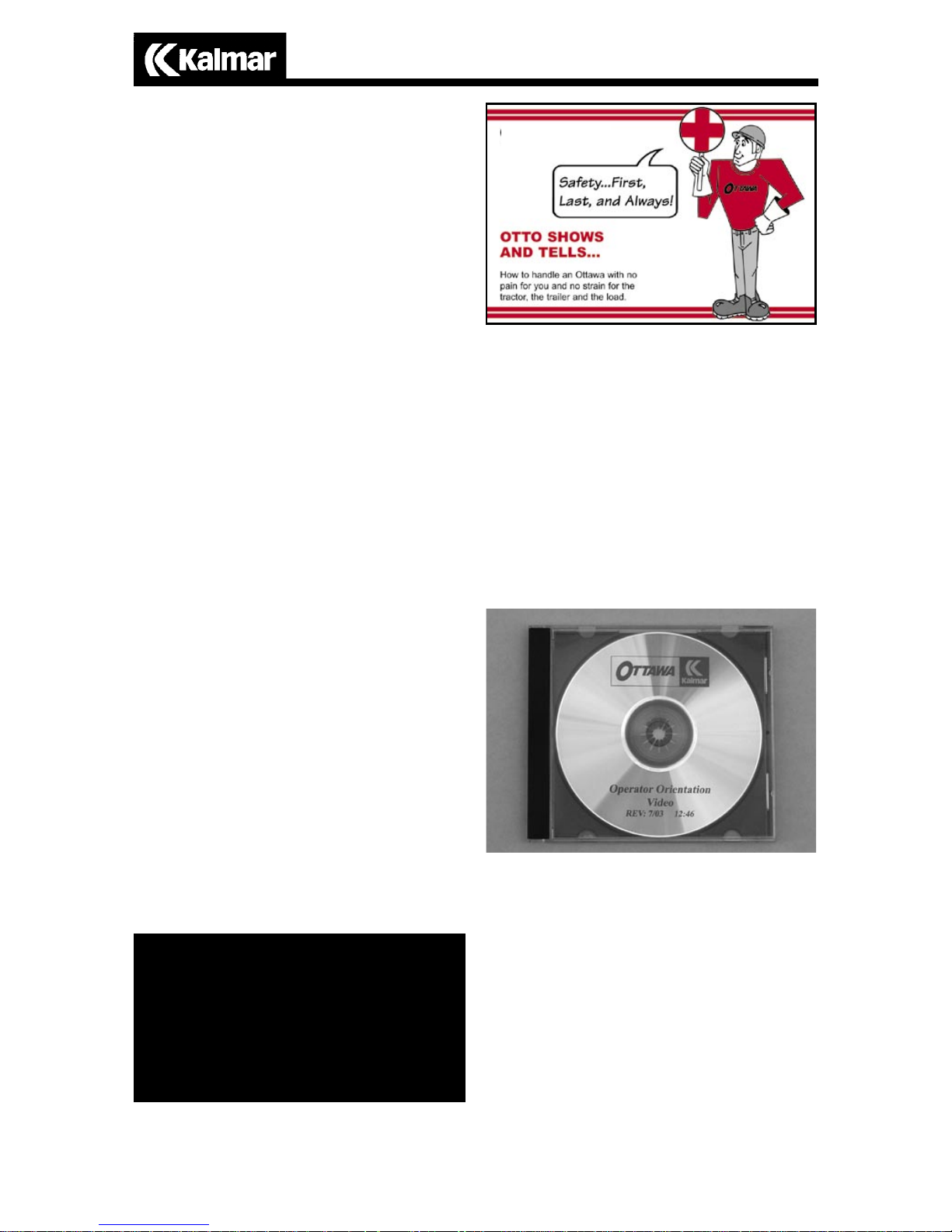
“OTTO Shows and Tells” booklet
Do not forget to read your safety booklet
that is provided with your Kalmar tractor.
This little manual is filled with important
operating tips. “OTTO” makes important procedures easy to remember with
pictures and simple explanations. If you
did not receive your “OTTO Shows and
Tells” booklet, contact your dealer for a
copy or contact Kalmar Industries Corp.
directly.
Operator Orientation Video
Kalmar Industries Corp. offers an Operator
Orientation Video CD. This video covers
important information that all Kalmar
operators must know. The video should be
used in conjunction with the “Otto Shows
and Tells” booklet and this manual to
instruct the operator on the proper operation of the Kalmar tractor. Shipped with
every truck, this video is also available
through your Kalmar dealer or directly
from Kalmar Industries Corp..
Page 10

9
SAMPLE PRE-OPERATION CHECKLIST
(Walk Around Inspection)
________ Check tires for damage and proper inflation
________ Check cab hold down latch (air suspension unit) for proper latching
________ Check all fluid levels: engine oil, hydraulic, and coolant
________ Drain any moisture from air tanks
________ Check cab doors and latches for proper operation
________ Ensure that all steps, walkways and handholds are installed and in good
working order
________ Start engine and check transmission fluid level with parking brake
applied and transmission shift selector in “neutral”
________ Check windshield wiper for proper operation
________ Check steering system for any binding. Make sure steering effort is
smooth and light
________ Check accelerator for proper operation. Should operate smoothly and
without any binding.
________ Check all rear view mirrors, adjust and clean if needed
________ Check cab and frame for any structural damage or cracks
________ Inspect trailer electrical cable and trailer air lines for damage. Make sure
both air lines are installed
________ Clean all windows if needed
________ Check transmission shift lever for any binding
________ Check boom control lever for proper operation
________ Check all lights for proper operation: headlights, turn signals, brake
lights, hazard lights, and marker lights
________ Check horn(s) for proper operation
________ Check and fill fuel tank
Page 11

10
Kalmar Terminal Tractor
North American Warranty Policy
KALMAR INDUSTRIES CORP (hereafter KALMAR) warrants to the original
owner that each new KALMAR Terminal Tractor will be free from defects in
material or workmanship under normal use and service for a period not to
exceed Three Hundred Sixty Five (365) days or Three Thousand (3,000) hours,
whichever occurs first, from commencement of service. The first 182 days or
1,500 hours both labor and parts will be warranted. The remaining 183 days
or 1,500 hours parts only will be warranted.
In addition, KALMAR warrants, to the original owner and in only the original
approved application, that each new KALMAR Terminal Tractor mainframe
will be free from defects in material or workmanship for a period of seven (7)
years. This extended frame warranty applies if, and only if: a) the tractor is
being used by the original owner; b) the failure cannot be attributed to lack
of routine maintenance; c) the tractor has not been involved in an accident;
d) the tractor is being used in the original KALMAR Terminal Tractor approved
application; e) the tractor has not been used in an application where the requirements of which are greater than the specification published at the time
of manufacture; f) the tractor frame has not been modified by welding on,
cutting into or drilling into the original structure.
The repair or replacement of defective parts or workmanship under the terms
of this warranty will be made by KALMAR or KALMAR Terminal Tractor
authorized Parts and Service Dealer, without charge for parts or labor, if
the defect occurs within the first 182 days of service and if the prepaid
returned parts are judged by KALMAR to be faulty or defective. If the defect occurs between 183 and 365 days of service KALMAR or KALMAR
Terminal Tractor authorized Parts and Service Dealer will repair or replace
parts only and will not reimburse for any labor charges. KALMAR will
not honor invoices for parts purchased from outside sources, unless written authorization is first given by the KALMAR Terminal Tractor Service
Department. Further, KALMAR will not honor invoices for labor charges,
unless the rate per hour charged and the number of hours involved are first
authorized by KALMAR.
THE OBLIGATION OF KALMAR UNDER THIS WARRANTY IS LIMITED
SOLELY AND EXCLUSIVELY TO REPAIRING OR REPLACING, AS KALMAR
MAY ELECT, ANY PART OR PARTS WHICH ARE RETURNED TO US, TRANSPORTATION PREPAID, AND WHICH, UPON EXAMINATION, ARE DETERMINED BY KALMAR OR THE SUPPLIER TO BE DEFECTIVE IN MATERIAL
AND/OR WORKMANSHIP. IN NO EVENT, SHALL KALMAR BE LIABLE FOR
ANY SPECIAL OR CONSEQUENTIAL DAMAGES.
Page 12

11
Excluded from this warranty are engines, Transmissions, Tires and batteries or
ant other components which have warranties covered by their manufactures.
The provisions of this warranty do not apply to the prime product or any component part thereof, which has been subject to misuse, or damaged through
negligence or accident, or has been repaired or altered by anyone other than
KALMAR or KALMAR Terminal Tractor authorized Parts and Service dealer.
Further excluded, are such parts as filters, belts, brake linings, lights, breakers,
and lubricants which are part of normal maintenance service replacements. The
KALMAR warranty does not cover towing charges or rental replacements.
A Warranty Registration form is mailed for every tractor. It is the obligation of
the purchaser to complete and sign the Warranty Registration form and return
it to KALMAR Terminal Tractor within 30 days after receipt of the tractor.
THIS WARRANTY IS A LIMITED WARRANTY AND IS IN LIEU OF
ALL OTHER WARRANTIES, EXPRESS OR IMPLIED, OF ANY KIND OR
NATURE WHATSOEVER.
KALMAR reserves the right, at any time, to make changes in the design, material, and/or specification of this product, or accessories thereof, without thereby
becoming liable to make similar changes in such equipment or accessories
previously manufactured.
KALMAR INDUSTRIES CORP.
415 East Dundee Street
Ottawa, Kansas 66067 USA
785 242 2200
Page 13

12
CONTENTS
Section “B”
INTRODUCTION ...............................................................................................14
VEHICLE ENTRY AND EXIT ................................................................................14
OCCUPANT RESTRAINT SYSTEM ....................................................................14
Seat Belt Operation ..............................................................................15
Suspension Type Seats ...........................................................................15
Seat Adjustment .................................................................................... 15
INSTRUMENT PANELS AND CONTROLS ........................................................16
Control and Display Location ...............................................................17
Control and Display Description ..........................................................18
STARTING THE VEHICLE ...............................................................................22
Ignition Switches ................................................................................22
Key Type Ignition ................................................................. .. 22
Push Button Starter ...............................................................22
PARKING THE VEHICLE ................................................................................ 23
AIR BRAKE SYSTEM ............................................................................... 23
Low Air Pressure Indicators .......................................................... .......24
Service Brakes ....................................................................................... 24
ABS .....................................................................................................25
Traction Control ..................................................................................26
PARKING BRAKE ............................................................................................26
Parking Brake and Trailer Air Supply Controls .....................................26
MANUALLY RELEASING TRACTOR SPRING BRAKES (CAGING) ..................... 26
TRAILER BRAKES .............................................................................................28
Trailer Air Lines ....................................................................................28
Operation
Page 14

13
ENGINE .........................................................................................................28
Starting the Engine ................................................................................29
Starting Procedure ......................................................... .. 29
Engine Shut Down ..............................................................................30
Shut Down Procedure .........................................................30
Engine Oil ............................................................................30
TRANSMISSION ...........................................................................................30
Parking with an Automatic Transmission .............................................31
HYDRAULIC FIFTH WHEEL LIFTING SYSTEM ..............................................31
Hydraulic Boom Operation ...............................................................31
Fifth Wheel Unlatch Control Valve .....................................................32
BASIC TRAILER SPOTTING STEPS ................................................................32
TOWING THE VEHICLE ...................................................................................34
Towing vehicle with front wheels suspended .....................................34
Towing vehicle with rear wheels suspended .......................................35
AXLES .............................................................................................................35
Axle operating temperature .................................................................35
Rear axles with locking or limited slip differentials ............................35
CAB TILTING AND LOWERING .....................................................................36
To tilt cab ............................................................................................ 36
To lower cab ........................................................................................37
ELECTRICAL ...................................................................................................38
Accessory connections ........................................................................38
Breakers, Relays and Fuses .................................................................. 38
Operation
Page 15
14
VEHICLE ENTRY
AND EXIT
The Kalmar tractor is designed for easy
entry and exit. The walkways, steps, and
handholds are designed with operator
safety in mind. As with any vehicle of this
type, care must be taken when climbing in
or out of your Kalmar tractor. Remember,
be careful!
WARNING - Never remove
factory installed walkways,
steps or handholds. Do
not operate your Kalmarunless all of the factory installed
steps, walkways and handholds
are installed and in good working
condition.
WARNING - Failure to
exercise caution when
entering and exiting this
vehicle can result in
personal injury.
1. Entry and exit should be made
slowly and carefully
2. A three-point stance should be
used. Three out of the four extremities (hands and feet) should be
in contact with the vehicle at all
times.
3. Face inward toward steps when
entering and exiting.
4. Keep steps, walkways and handholds in good condition.
5. Keep steps, handholds, walkways and shoes free of grease,
mud, dirt, fuel, ice and snow.
6. Use extra care during bad
weather, especially when steps and
handholds may be icy or wet.
INTRODUCTION
The following section on OPERATION
should be read carefully. It covers important information that every operator
must know before operating any Kalmar
tractor.
This manual is intended to cover the standard Kalmar tractor and some of the most
common options. Not all of the customer
ordered optional equipment or systems
are covered in this manual. If the operation of any component or system on your
vehicle is not covered in this manual, call
your Kalmar dealer for assistance.
CAUTION - Kalmar Industries Corp. highly recom-
mends that all individuals
that operate this vehicle have a
valid drivers license and have sufficient training to operate this type of
vehicle. Although most Kalmar tractors are not sold as highway legal
vehicles, this does not mean they
are intended to be operated by
untrained personnel. This manual is
not intended to be a training guide
for Yard Tractor operators. It is the
operator’s responsibility to obtain
sufficient training in order to operate this vehicle safely. DO NOT ATTEMPT TO OPERATE THIS VEHICLE
WITHOUT ADEQUATE TRAINING.
Operation
Page 16
15
OCCUPANT
RESTRAINT SYSTEM
THE KALMAR TRACTOR IS EQUIPPED
WITH SEAT BELTS. THEY SHOULD BE
USED WHENEVER THE VEHICLE IS IN
OPERATION.
SEAT BELT OPERATION
The seat belt system used on Kalmar
tractors is a lap type restraint with an
automatic retractor.
Before fastening the seat belt, be sure to
adjust the seat to a comfortable driving
position. To fasten the belt, pull the belt
low across the hips and insert the tongue
into the buckle.
To release the seat belt, press the button
on the buckle and the belt will retract
automatically.
SUSPENSION TYPE SEATS
All Kalmar tractors have a suspension type
seats as standard equipment.
WARNING—Due to the
vertical travel of suspension
seats, the operator must in-
sure that there is adequate
head clearance when the seat is at
the top of its upward travel.
Operation
SEAT ADJUSTMENT
Refer to seat manufacturer’s information
packet provided with the vehicle or to
the decal located on the seat base. Your
local Kalmar dealer can assist with any
questions.
Adjust the seat to the comfortable position
for the operator to have full control of all
cab controls and displays. This position is
obtained by changing the air pressure in
the suspension, which changes the height.
The fore and aft position is obtained by
moving the seat cushion and back on its
slides. Once this position is achieved,
tighten the seat belt tether securely on
both sides. The tether will restrain the seat
from raising above this position. Now,
the seat air suspension may be adjusted
to operator’s desired firmness.
WARNING - Do not adjust
drivers seat unless vehicle
is parked. The seat could
move suddenly and unexpectedly and cause loss of control
of the vehicle.
WARNING - The Kalmar tractor is designed
and equipped to carry
only the driver (unless built with a 2 man cab).
Never allow anyone to ride
anywhere inside or outside of
the cab. Carrying a passenger
is extremely dangerous and
can result in serious injury or
death. NEVER CARRY PASSENGERS WITH YOUR KALMAR.
Page 17

16
Operation
Page 18
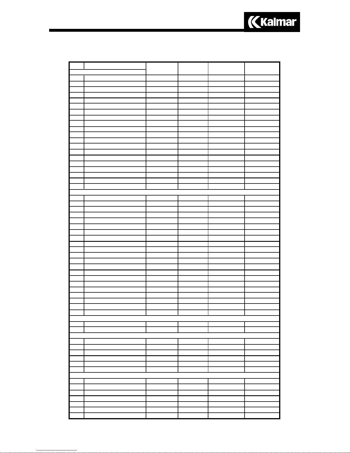
17
POS
1
2
3
4
5
6
7
8
9
10
11
12
13
14
15
16
17
18
19
20
21
22
23
24
25
26
27
28
29
30
31
32
33
34
35
36
37
38
39
40
41
42-52
53
54
55
56
57
58
59
60
61
62
63
65
66
NAME
WATER TEMP GAUGE
TACHOMETER
OIL PRESSURE GAUGE
SPEEDOMETER
FUEL GAUGE
AIR DIFFUSER
HEADLIGHT SWITCH
PANEL LTS DIMMER
INDICATOR LIGHT
INDICATOR LIGHT
INDICATOR LIGHT
INDICATOR LIGHT
INDICATOR LIGHT
INDICATOR LIGHT
INDICATOR LIGHT
INDICATOR LIGHT
INDICATOR LIGHT
STOP ENGINE IND LIGHT
INDICATOR LIGHT
LH TURN SIGNAL IND LT
VOLT METER
HOUR METER
A/C SWITCH
WASHER SWITCH
BEACON LT SWITCH
OPTIONAL SWITCH
FLOOD LIGHT SWITCH
ETHER START
IGNITION SWITCH
PUSH BUTTON START
HEATER CONTROLS
HEATER CONTROLS
HEATER CONTROLS
HI BEAM INDICATOR LT
RH TURN SIGNAL IND LT
INDICATOR LIGHT
HEATER FAN CONTROL
INDICATOR LIGHT
TRANS TEMP IND LIGHT
BRAKE AIR INDICATOR LT
WIPER SWITCH
GAUGE
STANDARD AIR GAUGE
2nd AIR GAUGE
TRACTOR PARK CONTROL
GAUGE
TRAILER PARK CONTROL
GAUGE
SHIFTER CONTROL
5th WHEEL CONTROL
5th WHEEL LATCH
DOLLY MASTER
LOAD GAUGE
INTER AXLE DIFF LOCK
DIFFERENTIAL LOCK
STD
OFF HWY
s
a
s
a
s
s
s
a
n
u
n
u
n
u
n
u
n
s
n
s
s
s
a
a
a
u
s
a
s
a
s
s
s
s
s
u
s
u
s
s
s
u
s
a
s
u
s
u
a
s
s
a
a
a
a
CUMMINGS
ISB/ISC
s
a
s
s
s
s
s
s
u
s
u
s
u
s
u
s
u
s
u
s
s
s
a
a
a
u
s
a
s
a
s
s
s
s
s
u
s
u
s
s
s
u
s
a
s
u
s
u
a
s
s
a
a
a
a
CATERPILLAR
3126
s
a
s
s
s
s
s
s
u
u
u
s
u
s
u
s
u
s
u
s
s
s
a
a
a
u
s
a
s
a
s
s
s
s
s
u
s
u
s
s
s
u
s
a
s
u
s
u
a
s
s
a
a
a
a
DETROIT
DIESEL S40 E
s
a
s
s
s
s
s
s
u
u
u
s
u
u
u
s
u
s
u
s
s
s
a
a
a
u
s
a
s
a
s
s
s
s
s
u
s
u
s
s
s
u
s
a
s
u
s
u
a
s
s
a
a
a
a
s=standard a=assigned options
u=unassigned options n=not available
Operation
Page 19

18
Ignition Switch ..........................17
Indicator Light Strip...................20
Optional Gauges.......................17
Optional Controls.....................17
Optional Switches.....................17
Parking Brake Control................21
Speedometer (optional).............20
Tachometer (optional)................20
Trailer Air Supply Control..........21
Transmission Shift Selector........21
Warning Light...........................20
Turn Signal Control...................21
Voltmeter..................................19
Windshield Wiper Control.........17
Windshield Washer...................17
Air-conditioner Switch ..............20
Air Pressure Gauge...................21
Beacon Switch (optional)..........17
Boom Control Lever..................21
Coolant Temperature Gauge......19
Engine Oil Pressure Gauge.......19
Emergency 4 Way Flasher.........21
Fan Control (heater/air-conditioner) 20
Fifth Wheel Unlatch Control.....21
Floodlight Switch......................20
Fuel Gauge...............................19
Headlight Control Switch..........19
Heater Controls........................20
High Beam Indicator.................20
High Beam Switch....................21
Hour Meter...............................19
CONTROL AND DISPLAY DESCRIPTION
Transmission Temp.
Operation
Page 20

19
PANELS 1 and 2
1. Dash Panel Light Dimmer
2. Headlight/Running Light Control
This switch controls headlights and running lights on the tractor and trailer. This
switch also activates the interior dash and
gauge lights when either the headlights or
the running lights are on. The switch has
three positions.
3. Fuel Gauge
Indicates the level of fuel in the fuel tank
in 1/4 increments.
4. Engine Oil Pressure Gauge
Indicates the engine oil pressure in P.S.I.
5. Coolant Temperature Gauge
Indicates the temperature of the engine
coolant in degrees Fahrenheit.
6. Voltmeter (Ammeter Optional)
Indicates the status of the charging system
in volts. If the engine is running the gauge
indicates the alternator output voltage. If
the engine is not running the voltmeter indicates the output voltage of the battery.
7. Hour Meter
Indicates engine operating hours.
Operation
Page 21

20
8. Heater Control
This lever controls the heater temperature.
The full down position shuts off the heater.
The lever can be adjusted to provide the
desired amount of heat by moving it up
from the OFF position.
9. Fan Speed ON/OFF Switch
The switch has four positions. Full counterclockwise is the OFF position.
10. Windshield Wiper Control
This control operates the windshield
wiper. Turning the control clockwise increases the speed of the wiper. Turning
the control counterclockwise completely
will park the wiper.
11. Floodlight Control
Activates a normally rear facing flood
light. The switch is two position, up (ON)
and down (OFF).
12. Air-conditioner Switch (Optional)
This switch activates the air-conditioning
compressor when the optional air-conditioning is installed.
13. Tachometer (Optional)
Indicates engine R.P.M.
14. Speedometer (Optional)
Indicates vehicle speed in M.P.H. or K.P.H.
This gauge may also come with an odometer feature built in.
15. Heater/Air-Conditioner Duct
Directional and closeable duct for the
heater and air-conditioner.
Indicator Light Strip
The indicator lights are located along the
top of dash panels 1 and 2. These panels
contain the 5 STANDARD indicators and
any optional indicators. The 5 standard
indicators are listed below:
1. Left Turn Signal Indicator
(green arrow) Indicates left hand turn
signal is on when flashing.
2. Right Turn Signal Indicator
(green arrow) Indicates right hand turn
signal is on when flashing.
3. High Beam Indicator
(blue light symbol) Indicates high beams
are on when illuminated.
4. High Transmission Temperature
(trans temp) Indicates transmission fluid
temperature is above 300° F. when
illuminated.
5. Low Air Pressure
(brake air) Indicates system air pressure is
below 70 P.S.I. when illuminated.
Operation
Page 22

21
1. Standard Air Gauge
Indicates air pressure in the air system
in P.S.I.
2. 2nd Air Gauge
Indicates air pressure in the air system
in P.S.I.
3. Transmission Shift Selector
This control selects the operating range
of the transmission. (See page 30, Transmission)
4. Boom Control Lever
This control operates the hydraulic boom
and fifth wheel. (See page 31, Hydraulic
Boom Operation)
5. Fifth Wheel Unlatch Control
This control engages the fifth wheel jaw
locking mechanism. (See page 32, Fifth
Wheel Unlatch Control)
6. Parking Brake Control
This control operates the parking brakes
on the vehicle and trailer. (See page 26,
Parking Brakes)
7. Trailer Air Supply
This control activates the trailer air supply.
(See page 26, Parking Brake and Trailer
Air Supply)
Figure 1
A High Beam Switch
B Turn Signal Lever
C Emergency Flasher Switch
The column mounted control on the
Kalmar tractor has three functions. It is
located on the left hand side of the steering column (Fig. 1).
1. Moving the lever (Fig. 1, B)
forward activates the right turn signal.
Moving the lever to the rear activates the
left turn signal. The turn signal is not self
canceling and must be returned to the
center (off) position manually after it is
engaged. The green arrows on the dash
panel light up and flash when the switch
is activated.
2. The button on the end of the lever
operates the high beam lights (Fig. 1, A).
The headlights must be on for the switch
to work. When the high beam headlights
are on, the high beam indicator on the
dash will light up.
3. The pull out switch under the
lever activates the emergency flashers
(Fig. 1, C). Pulling out on the switch
turns the flashers on. To turn the flashers
off, move the turn signal lever forward or
backwards.
PANELS 4 and 5
TURN SIGNAL, HIGH BEAM AND
EMERGENCY FLASHER CONTROL
Operation
Page 23

22
KEY TYPE IGNITION
There are three positions; OFF, ACCESSORY and RUN/START. The full left
(counterclockwise) position is the OFF
position. The second position to the right
(clockwise) is the ACCESSORY position.
The third position to the right (clockwise)
is the RUN/START position.
The RUN/START position is used to engage the starter motor. Moving the switch
to the full right position engages the starter
and upon release of the key, the switch
automatically stays in the RUN position.
The ACCESSORY position activates the
tractor’s electrical accessory circuit.
The OFF position cuts all power to the
electrical system and shuts down the
engine.
NOTE - The Off position on the standard three
position key type switch is designed to function
as the engine stop. There is no other engine
stop device other than the ignition switch on
the standard Kalmar tractor.
PUSH BUTTON STARTER
Push button starters are optional on Kalmar tractors. There are two basic types of
toggle ignition switches, three position
and two position.
The three position type functions like the
standard key type with OFF, ACCESSORY
and RUN positions. The button engages
the starter when the switch is in the RUN
position only.
The two position switch has only the OFF
and RUN positions. It has no provision for
and ACCESSORY position. The button engages the starter in the RUN position only.
DRIVER CONTROLLED
DIFFERENTIAL LOCK
(Optional on drive axles)
Drive axles may be equipped with a driver
controlled differential lock. This is an air
actuated traction device that can be
manually controlled inside the cab by the
operator. By actuating a dash mounted
control, the operator can lock or unlock
the differential.
NOTE: When this differential is fully locked the
vehicle will have reduced steering capability.
The driver must limit the use of the differential
to slow speeds. Also, the differential must
not be engaged when traveling down steep
grades when traction is limited. Refer to axle
manufacturer for operational & maintenance
procedures.
STARTING THE
VEHICLE
(See page 29, Starting The Engine)
IGNITION SWITCHES
The standard ignition switch on the
Kalmar tractor is a key type, similar to the
kind found on automobiles. Push button
and other types of ignition switches are
installed as optional equipment.
Operation
Page 24

23
ing it in gear. Always place the
transmission shifter selector in the
“Neutral” position.
3. Never park a tractor trailer combination unless the trailer parking
brakes are operational and applied.
NOTE - If the vehicle is parked in gear, the
vehicle will not start.
AIR BRAKE SYSTEM
DANGER - Brakes must
be kept in proper working condition. Operating a
vehicle with poorly maintained, brakes or worn out brakes
can cause a loss of vehicle control.
This may lead to serious injury or
death. Never operate the vehicle
unless the brakes are working
properly.
CAUTION - Do not allow
moisture to collect in the
air tanks. The air tanks must
be drained daily. Failure to
drain the air tanks can damage the
air brake system.
Kalmar tractors come equipped with
pneumatic (air) brake systems. This system
has two basic parts, the service brakes,
and the spring parking brakes.
The service brakes are the part of the system that the driver uses when he operates
the foot operated treadle valve (or foot
pedal) in the cab (Fig.1 page 24).
CAUTION - If the engine
does not start within 30
seconds, release the starter
switch and wait 3 minutes to allow
the starter motor to cool. If after 3
repeated attempts, the engine still
fails to start, stop and determine
the cause. The starter motor may be
damaged by repeated attempts to
start the engine.
NOTE - Some vehicles may be equipped with
optional shut down systems or optional starter
switches. Contact your Kalmar dealer if you
have any questions regarding the operation
of any optional starter switches or shut down
systems.
PARKING THE
VEHICLE
(See page 30, Transmission)
(See page 26, Parking Brake)
Standard Kalmar tractors are equipped
with an Allison automatic transmission
and spring operated parking brakes. Allison transmissions are unlike an automobile transmission in one important regard.
They do not have a park position.
When parking your Kalmar tractor there
are some important rules that must be
followed.
DANGER - Failure to
observe the following rules
when parking the vehicle
may result in serious injury
or death.
1. Always apply the parking brake.
2. Never park the vehicle by leav-
Operation
Page 25

24
air pressure in the system. The warning
buzzer will shut off after air pressure has
reached 70 P.S.I.. (See page 21)
If the warning light and buzzer do not shut
off at least 5 minutes after start-up, shut
the engine down and determine why the
air system is not charging.
If the Low Air indicator light or buzzer
indicates a loss of air pressure while
driving, the vehicle should be stopped
immediately. The vehicle should not be
operated until the air system is repaired
and functioning properly.
Danger - Do not operate
the vehicle if the air brake
system is not working
properly.
SERVICE BRAKES
The Service Brake system is controlled by
a foot operated treadle valve (foot pedal)
in the cab. This is the left hand pedal, located to the right of the steering column
(Fig. 1, page 24). The amount of foot
pedal pressure determines the amount of
air pressure delivered to the brakes. The
more pressure on the treadle valve (pedal),
the more braking force applied. The service brakes should be applied in smooth
constant applications. They should not be
pumped or fanned while slowing or stopping the vehicle. Even in an emergency
stop situation, the service brakes should
not be rapidly “pumped”.
NOTE - Air brakes do not respond like the
brakes in a car, and pumping them in an
emergency stop is not advised. Rapidly
“pumping” the brakes is more likely to use up
all of the air in the system and cause the spring
brakes to apply and lock the rear wheels. This
will cause an out of control skid.
Figure 1
A Accelerator Pedal
B Brake Treadle/Pedal
The service brakes are the primary brakes
used by the operator. The service brakes
require air to operate. If there is insufficient air in the system, the service brakes
will not operate.
The spring brakes are used for parking
the vehicle. They are also called the
parking brakes because the parking brake
control applies the spring brakes. The
spring brakes use the mechanical force
of a spring to operate. They do not need
air to operate, but they do need air to be
released. If there is a loss of pressure in
the system, these brakes will automatically
apply. This is why the spring brakes are
sometimes called “emergency” brakes.
Remember, if there is no air in the system
the spring (parking) brakes will not fully
release.
LOW AIR PRESSURE INDICATORS
When air pressure in the brake system is
below 70 P.S.I., the warning buzzer will
sound and the LOW AIR warning indicator on the dash panel will light up. The
air pressure gauges should indicate low
Operation
B
A
Page 26

25
braking ability of the tractor trailer
combination and creates a serious
hazard. This increases the possibility of an accident and could result
in serious injury or death.
WARNING - Never operate the vehicle when
system air pressure is
below 70 P.S.I. There may
not be enough air in the system to
stop or slow the vehicle. Have the
brake system checked by a certified air brake mechanic if there is
any doubt about the brake system
performance.
A.B.S.
Some trucks may be equipped with the
Antilock Braking System (A.B.S.). The
A.B.S. system is designed to prevent wheel
lock up during hard braking.
Trucks equipped with A.B.S. have an indicator light located in dash panel number
one. The indicator light will warn the
operator if there is a potential problem in
the system.
Trucks should not be operated if the indicator light is on. Contact your nearest
Kalmar dealer for qualified service on the
A.B.S. system.
Trucks built with A.B.S. after March of
2002 will have the capability to check
the trailer for a properly operating system.
After connecting a trailer to the truck, the
system will run a diagnostics check. If a
problem is detected with the trailer side of
the A.B.S. system, a trailer warning indicator light on the dash will illuminate.
While the engine is running, the air
compressor replenishes the brake system
air supply. This air supply provides the
pressure necessary to operate the service
brakes.
The service brakes require at least 70
P.S.I. to operate effectively. If the system
is not up to at least 70 P.S.I., there may
not be enough air in the system to stop
the vehicle. Several hard brake applications can quickly deplete the pressure in
the air system and could possibly cause
the pressure to drop below 43 P.S.I.. If this
happens the spring brakes will apply automatically, possibly causing the operator
to loose control of the vehicle.
The service brake system is integrated
with the parking brake system. Should the
service brake system fail because of a lack
of air pressure (below 43 P.S.I.), the spring
brakes will automatically be applied for
emergency braking.
WARNING - Rapid successive brake application
and release, sometimes
referred to as “fanning” or
“pumping” the brakes, should be
avoided. This is an inefficient way
to slow or stop a vehicle with air
brakes and may use up all of the
air in the system before the vehicle
is stopped or slowed completely.
This could result in serious injury or
death.
WARNING - Always
connect both trailer air
lines when towing a trailer.
Failure to connect both the trailer
service (BLUE), and the trailer supply (RED) air lines greatly reduces
Operation
Page 27

26
Trouble-shooting or clearing fault codes
is performed at the EC module mounted
in the left front wheel well.
TRACTION CONTROL
Automatic traction control (A.T.C.) is
available as an option on trucks equipped
with the Antilock Braking System. When
activated, the A.T.C. active/warning lamp
will be on and the system will limit wheel
spin during hard acceleration. The system
is activated by turning on the A.T.C. enable/disable switch located on the dash.
During activation, the warning lamp will
blink to advise the driver that drive-wheel
spin is occurring.
A.T.C. can be disabled while the vehicle is
stationary or in motion. However, A.T.C.
will not re-enable until the vehicle comes
to a complete stop, even with the switch
turned to the enable position.
Danger - Never operate
the vehicle if the truck
or trailer A.B.S. warning
(indicator) lights remain
illuminated.
PARKING BRAKE
Otttawa tractors are equipped with spring
brakes of parking. The parking system is
operated manually by a cab mounted
parking brake control valve (Fig 1) (Also
see page 21, Items 6 and 7)
The purpose of the parking (spring) brakes
are to hold the vehicle while in the parked
position.
(RED)
(YELLOW)
WARNING-Never apply
the parking brake during
normal driving. Doing this
will lock the rear wheels,
possibly causing an uncontrolled
stop.
PARKING BRAKE AND TRAILER
AIR SUPPLY CONTROLS
NOTE - Air pressure in the system must be at
least 70 P.S.I. before the Parking Brake Control
or the Trailer Air Supply Control can be pushed
in (releasing the spring brakes).
NOTE - If the tractor air system is completely
discharged, the Trailer Parking Brake Controls
will be applied. The trailer parking brake
should not be released until the tractor brakes
are rolling.
Figure 1
Parking Brake and Trailer
Air Supply Controls
MANUALLY
RELEASING
TRACTOR SPRING
BRAKES (CAGING)
When air pressure in the system drops below approximately 43 P.S.I., the spring
Operation
Page 28

27
1. Shut the engine off and remove the
key.
2. BLOCK ALL wheels front and rear to
prevent the vehicle from rolling forward
and backwards.
3. Determine whether the chamber has an
internal (FIGURE 1) or external (FIGURE
2) caging tool. Proceed to step 4 with
an externally mounted tool. Step 8 for
internal types.
4. Remove the access plug from the brake
canister.
5. Insert the caging tool into the access
hole, “T” end first.
Figure 2
6. Turn the caging tool 1/4 turn to engage
with the slot on the pressure plate.
7. Try to pull the caging tool out, it should
not pull out. If it does repeat steps 5 and 6.
8. Thread the nut and washer down onto
the threaded end of the caging tool all the
way to the canister.
9. Tighten the nut until the threaded portion of the release tool is out. It should
extend approximately 3” out of the nut.
3.00 inches - Type 2430 and 3030 Chambers
4.00 inches - Type 3036 and 3636 Chambers
parking brakes will apply automatically. To
release the spring brakes, the air pressure
must be returned to 70 P.S.I.. If the system
cannot be recharged and the vehicle must
be moved, the spring parking brakes can
be released manually (caged).
To release the spring brakes, the actual
spring in the brake canisters must be mechanically compressed. A release stud, or
spring caging tool, must be used to manually compress the brake chamber.
DANGER - Never manually
release (cage) the spring
breaks before the wheels
are properly blocked. If the
wheels are not properly blocked
before releasing the spring brakes,
the vehicle may move unexpectedly. This could result in serious
injury or death.
Figure 1
The following steps can be used to release the standard brake chambers used
on most Kalmar tractors. If your vehicle
is equipped with other optional brake
chambers, refer to that manufacturer’s
operation or service manual.
Operation
Page 29

28
CAUTION - Never use an
impact wrench to tighten
the nut onto the release
bolt. Never exceed the
above lengths and never exceed 50
lbs-ft. of torque on the release nut
or the chamber may be damaged.
TRAILER BRAKES
Kalmar tractors are designed to use the
trailer’s brakes when towing trailers. All
Kalmar tractors are equipped with a trailer
Supply air line and a trailer Service air
line. The service line is BLUE. The supply
line is RED.
When the vehicle is towing a trailer and
the service and supply line are connected
to the trailer, the trailer brakes become
part of the tractor’s brake system. The
tractor service brakes control the trailer
service brakes. The tractor parking brake
control operates the tractor and trailer
spring brakes. This is why it is critical that
the operator always connect both air lines
to the trailer.
TRAILER AIR LINES
The service air line (blue hose) operates
the trailer service brakes. The supply air
line (red hose) only supplies air to the
trailer spring brakes to release them. If
only the supply air line is attached to the
trailer, the trailer service brakes will not
operate. The tractor service brakes will be
doing all the braking for the combination
and braking distances will be dramatically increased. Without the trailer service
brakes working, jack-knifing and loss of
vehicle control is much more likely during
heavy braking.
WARNING - Always
connect both trailer air
lines when towing a trailer.
Failure to connect both
the trailer service (BLUE), and the
trailer supply (RED) air lines greatly
reduces braking ability of the tractor trailer combination and creates
a serious hazard. This increases the
possibility of an accident and could
result in serious injury of death.
ENGINE
Kalmar tractors come equipped with a
variety of engines. Kalmar provides the
engine manufacturer’s operation manual
with each vehicle. It is the operators responsibility to read the engine operation
manual and follow all instructions provided by the engine manufacturer.
Engine performance is very important
to the efficient operation of the Kalmar
tractor. Failure to properly maintain and
operate any engine can lead to very
costly repairs and extensive down
time. KNOW YOUR ENGINE AND
MAINTAIN IT!
NOTE - This manual only contains basic
information on engine operation that apply
specifically to the Kalmar tractor, or is
applicable to all diesel engines.
If you did not receive an engine operation
manual, contact your Kalmar dealer.
CAUTION - Failure to read
and follow engine manufacturer’s instructions regarding
engine operation may lead
to severe engine damage. Read the
Engine Operation Manual before
operating this vehicle.
Operation
Page 30

29
To start a vehicle equipped with the
standard electrical starting system, follow
these steps:
STARTING PROCEDURE
NOTE - All Kalmar tractors are designed to
start in NEUTRAL ONLY. The starter should not
operate if the vehicle is in any other gear.
1. Set the parking brake.
2. Place the transmission control in NEUTRAL.
3. Apply the service brakes using the floor
mounted treadle valve and hold the brakes
in the position.
4. Insert the ignition key into the switch
and rotate the key clockwise to the RUN
position.
5. Wait for the “Wait to Start” light on the
dash to go out if the vehicle is equipped
with one.
6. Turn the key to the start position. When
engine starts, release the key and allow the
switch to remain in the Run position.
CAUTION - If the engine
does not start within 30
seconds, release the starter
switch and wait 3 minutes
to allow the starter motor to cool.
If after 3 repeated attempts, the
engine still fails to start, stop and
determine the cause. The starter
motor may be damaged by repeated attempts to start the engine.
STARTING THE ENGINE
(See page 22, Starting the Vehicle)
WARNING - Always set
parking brake and place
shifter in neutral before
attempting to start engine. Failure to do so may cause
the vehicle to move suddenly and
unexpectedly when the starter is
engaged.
WARNING - All Kalmar
tractors are designed to
start in NEUTRAL ONLY. If
the vehicle you are operating starts while it is in gear, DO
NOT OPERATE THE VEHICLE. Shut
the vehicle down and have the neutral lock-out switch repaired before
operating the vehicle.
DANGER - Never attempt
to start the vehicle from
any position other than the
driver’s seat. Attempting
to start the vehicle while standing, outside of the cab, or in the
engine compartment may cause the
vehicle to move uncontrolled and
cause serious injury or death.
The following is provided as general
guideline information. Always follow
all instructions provided in the engine
manufacturer’s operation manual. Different makes and models of engines have
different operating characteristics and
requirements. There are some important
guidelines to follow when starting any
Kalmarequipped with a diesel engine.
These are listed below.
Operation
Page 31

30
ENGINE OIL
Always refer to the engine operation manual for complete information on engine oil
requirements. Service intervals, oil types
and refill quantities are all covered in the
engine operation manual. READ IT!
TRANSMISSION
Standard tractors are equipped with an
Allison Automatic Transmission, RDS series. These heavy duty transmissions are
designed for stop and go operation. An
Allison Transmission operator’s manual is
provided with every Kalmar. This manual
provides important information on operation of the RDS series transmissions.
The following information can be found
in your Allison Operator’s Manual:
1. Gear Selection
2. Shifting the Transmission
3. Driving Tips
4. Care and Maintenance
5. Check oil level w/shifter
6. Check/clear fault codes
WARNING - The operator
of this vehicle must read
and follow the instructions
in the Allison Operator’s
Manual. Failure to do so may lead
to serious vehicle damage and
personal injury.
The forward to reverse shifts of the transmission are controlled by the “ECM”.
ENGINE SHUT DOWN
Diesel engines generate large amounts of
heat. Internal engine parts on any diesel
engine need to cool down before the engine is shut off. The operator should allow
the engine to idle for at least 3 minutes
prior to shutting the engine down. This
cool down period allows the coolant to
dissipate internal engine heat. Shutting a
hot engine down without a cool down period may cause an immediate and excessive increase in engine temperature. This
could severely damage internal engine
components.
NOTE - Always refer to the engine operation
manual for complete information on engine
shut down procedures.
SHUT DOWN PROCEDURE
1. Place transmission in neutral.
2. Set parking brake.
3. Allow engine to idle at low idle for at
least 3 minutes.
4. Turn ignition switch to OFF position (if
your vehicle is not equipped with an ignition operated engine shut down then use
the engine shut down button or control
to stop engine).
5. Make sure all electrical accessories
and lights are off and the vehicle is in
neutral.
CAUTION - Failure to follow engine manufacturers
guidelines regarding engine
shut down procedures may cause
severe engine damage.
Operation
Page 32

31
is located on the console to the right of the
seat and next to the shift lever (Page 21).
Figure 1
A - Fifth Wheel Plate
B - Boom
DANGER - Never raise or
lower the boom while the
tractor and trailer combina-
tion are moving. Raising the
boom while the tractor and trailer
are moving creates a “roll over”
hazard and may cause the vehicle
to roll over. Possibly resulting in
injury of death. DO NOT OPERATE THE BOOM CONTROL LEVER
WHILE THE VEHICLE IS MOVING A
TRAILER.
To Raise Fifth Wheel: To raise the boom
the engine must be running. Pushing the
lever to the “UP” position, indicated on
the boom operating lever, raises the fifth
wheel. To increase the rate of travel of the
boom, the engine may be idled higher
while the vehicle is in NEUTRAL ONLY.
To Lower Fifth Wheel: To lower the boom,
the engine must be running, the transmission in NEUTRAL. Pulling the boom control lever to the “DOWN” position,
PARKING WITH AN
AUTOMATIC TRANSMISSION
The Allison RDS series transmissions do
not have a “PARK” position like an automobile transmission. For information on
how to properly park your Kalmar, see the
following sections in this manual:
Page 23, Parking the Vehicle
Pages 26 thru 28, Parking Brake
HYDRAULIC FIFTH
WHEEL LIFTING
SYSTEM
The standard fifth wheel lifting system on
Kalmar tractors is hydraulically operated.
A P.T.O. and hydraulic pump mounted
on the transmission provide the hydraulic power to operate the Hydraulic Fifth
Wheel Lifting System. The Fifth Wheel
is mounted to a hydraulically operated
“Boom” (fig. 1). This “Boom” assembly
is attached to the frame at a pivot behind
the cab. The system operates like a large
hydraulic floor jack.
The following are general operating instructions and may not apply to you particular vehicle. If there are any questions
regarding the operation of your vehicle or
a particular option, contact your Kalmar
dealer.
HYDRAULIC BOOM OPERATION
The hydraulically operated boom is controlled by a lever inside the cab. The lever
Operation
Page 33

32
marked on the boom operating lever, lowers the boom and fifth wheel. To increase
the rate of travel of the boom, the engine
may be idled higher while the vehicle is in
NEUTRAL ONLY. Standard configuration
of the boom allows both power up and
down capability.
FIFTH WHEEL UNLATCH
CONTROL VALVE
The Kalmar tractor comes standard with
an air operated fifth wheel unlatch cylinder. The cylinder is operated by a “push
type” valve located on the right hand console behind the shifter (Page 21). Pressing
the fifth wheel unlatch valve opens the
king pin jaws in the fifth wheel. After the
jaws are opened, they remain open until
the fifth wheel is connected to a trailer
kingpin.
NOTE - When pulling out from under a trailer,
the control must be depressed and held until
the fifth wheel is clear of the trailer king pin.
BASIC TRAILER
SPOTTING STEPS
NOTE - The following information is for
reference only. Kalmar Industries Corp. highly
recommends using the following information
to create procedures that match your particular
application and vehicle. It is the operator’s
responsibility to ensure that proper trailer
moving procedures are used for a particular
situation and vehicle application.
1. Maintain optimum tractor air pressure
(120 PSI). The fifth wheel should be in
the FULL DOWN position. Be absolutely
positive that the fifth wheel jaws are in
the UNLATCH position by depressing the
unlatch control valve located to the right
of the shifter. (See page 21).
2. Line the tractor up to the front of the
trailer by centering the fifth wheel to the
center line of the trailer. Make sure that
the tail of the fifth wheel is BELOW the
trailer skid ramp.
3. Back the tractor UNDER the trailer until
the ENTIRE fifth wheel DISAPPEARS UNDER the front edge of the trailer floor/skid
plate.
4. With your foot firmly on the brake
treadle and the tractor shift lever in
NEUTRAL, move the boom control lever
to the UP position and raise the trailer
until the trailer support is JUST OFF THE
GROUND. DO NOT raise the trailer any
more than a few inches to provide clearance between the trailer landing gear and
the ground at this step.
5. After you have obtained adequate
ground clearance at the trailer landing
gear, place the shift selector in REVERSE,
release your foot from the brake treadle
and back FIRMLY into the kingpin jaws
until you feel full engagement. REMEMBER, the latching jaws in the fifth wheel
MUST BE FULLY IN THE UNLATCH
POSITION BEFORE attempting kingpin
engagement.
6. Place the transmission shift lever into
a forward drive gear and give a “TUG” at
the kingpin to ensure positive lock of the
jaws around the kingpin. BE PREPARED to
stop if the fifth wheel jaws have not fully
latched to avoid pulling out from under
the trailer and dropping it.
7. Place the shift lever in the NEUTRAL
position and raise the boom using the
boom control lever. Raise the fifth wheel
to the necessary height to maintain ground
clearance while towing the trailer to the
new location. Be aware of potential overhead damage to a trailer if it is
Operation
Page 34

33
raised too high.
8. Once proper trailer height is reached,
apply the tractor parking brake. Now
hook BOTH the trailer emergency and
service airlines to the trailer (blue & red
airlines) and plug in the trailer electrical
cable.
9. With the brake treadle FULLY applied,
push in BOTH the parking brake control
(yellow) and the trailer air supply (red),
this will charge the trailer air supply and
release the trailer spring/parking brakes.
10. After the tractor air system is fully
charged, move the transmission shift lever
to the proper gear and release pressure on
the foot operated brake treadle and allow
the vehicle to roll a VERY SHORT distance
and then depress the brake treadle again
to stop the vehicle. This procedure will
insure that the service brakes on the trailer
are working properly. NOW, and ONLY
NOW, are you ready to move (“SPOT”)
the trailer.
11. Once the trailer is relocated and
the vehicle combination is completely
stopped, place the shift lever in NEUTRAL
and pull out on the trailer air supply
control (red). This will apply the trailer
parking brakes only. The parking brake
control (yellow) should remain “in”, with
the tractor parking brake released.
12. Using the boom control lever, lower
the trailer until the trailer supports are
resting completely on the ground.
13. Disconnect and STORE the air lines
and electrical cable.
14. DEPRESS and HOLD the fifth wheel
unlatch control valve as you slowly pull
away from the trailer. Once the fifth wheel
is completely clear of the kingpin, release
the fifth wheel unlatch control and go the
next trailer.
WARNING - When the tractor is operated on public
streets or highways, the
5th wheel manual secondary lock MUST be engaged.
The secondary lock is engaged by
removing the hairpin clip on the
lock handle allowing the lock to
pivot behind the locking yoke. The
fifth wheel MUST be in the DOWN
position to operate the vehicle on
public streets or highways.
WARNING - Never raise
or lower the boom while
the vehicle has a trailer at-
tached and is in motion.
WARNING - DO NOT
EXCEED 15 MPH WHEN
TOWING TRAILERS. Op-
erating at speeds in excess
of 15 MPH may lead to loss of
vehicle control. NEVER take turns
at excessive speeds, this may cause
the vehicle and trailer to roll over.
The majority of roll over accidents
are caused by excessive cornering speed. ALWAYS SLOW WHEN
CORNERING. Roll over accidents
may lead to serious injury or death.
WARNING - Never tow
trailers without BOTH the
service and emergency brake
lines connected to the trailer.
Never tow trailers without functioning
service and emergency brake systems.
Operating the vehicle while towing
trailers without functioning trailer brake
systems may lead to loss of control of
the vehicle, serious injury or death.
Operation
Page 35

34
TOWING VEHICLE WITH FRONT
WHEELS SUSPENDED
It is not recommended to tow a vehicle
with the front wheels lifted and the rear
drive wheels on the road. This practice
may result in serious vehicle damage.
Pay close attention to the following rules
to prevent vehicle damage if you must
tow your Kalmar with the rear wheels on
the road.
WARNING - Always obey
the following when towing
a Kalmar tractor with the
front wheels lifted and the
rear wheels on the road.
1. Always use a rigid towing bar or
properly restrain the towed vehicle.
Using a chain or cable to tow the
vehicle is not recommended.
2. Always disconnect the drive line
to the rear drive axle(s), or remove
all axle shafts from all rear drive
axles.
3. Always cage the spring brakes on
all rear drive wheels. (See page
B-14, Manually Releasing Spring
Brakes) A loss of air pressure could
occur while towing the vehicle. This
would apply the spring/parking
brakes and lock the rear wheels on
the towed vehicle.
WARNING - When manually releasing spring brakes,
make sure that the vehicle
wheels are properly blocked.
If the wheels are not blocked, the
vehicle could move suddenly when
the spring brakes are released and
cause sever injury.
WARNING - Never tow a
trailer above the minimum
height required to clear
the landing gear from the
ground. Lifting the fifth wheel and
trailer too high drastically raises the
center of gravity of the trailer and
increases the chance of a roll over.
TOWING THE
VEHICLE
Towing a vehicle requires special equipment and training. Kalmar Industries Corp.
recommends that a professional towing
service be used when towing a disabled
Kalmar.
The best way to tow a Kalmar tractor is
with the rear wheels lifted off the road.
This prevents any possible damage to the
transmission and drivetrain. Towing the
vehicle with the rear wheels lifted avoids
having to disconnect the driveline or axle
shafts. Also, towing with the rear wheels
lifted does not require the spring brakes
to be caged unless there are spring brakes
on the front wheels.
If it is impossible to tow the vehicle with
the rear wheels lifted, be sure to follow the
steps listed below, “Towing Vehicle with
Front Wheels Suspended”.
CAUTION - Some Kalmars
are equipped with “Off
Highway” tires. Tire damage
may occur if towed on road.
Operation
Page 36

35
Fahrenheit (37 deg. Celsius) above ambient temperature. Operating temperatures
above 230 deg. F significantly increase
the rate of lubricant oxidation and shortens the effective life of the lubricant. This
makes more frequent changes necessary.
REAR AXLES WITH LOCKING
DIFFERENTIALS
Kalmar tractors may be equipped with
a variety of special axle and differential
combinations. Because of the effect of
special differentials on vehicle operation,
it is important to understand how your
particular differential operates. Locking or
limited slip differentials are not standard
on Kalmar tractors. If you do not know if
your vehicle is equipped with a special
axle and differential, contact your Kalmar
dealer.
“NO SPIN” POSITIVE LOCKING
DIFFERENTIAL
Kalmar tractors may be equipped with an
optional “No Spin” differential. This locking differential has very special operating
characteristics. IT IS VERY IMPORTANT
FOR THE OPERATOR OF A VEHICLE
EQUIPPED WITH THIS FEATURE TO OBTAIN AND FOLLOW ALL OF THE OPERATION AND MAINTENANCE INFORMATION PROVIDED BY THE DIFFERENTIAL
MANUFACTURER. Contact your Kalmar
dealer for assistance on operating and
maintaining this differential.
WARNING - If the disabled
vehicle is connected to
a tow vehicle before the
spring brakes are released,
make sure that the tow vehicle’s
parking brakes are applied and
it’s wheels are blocked to prevent
movement.
TOWING VEHICLE WITH
REAR WHEELS SUSPENDED
The recommended way to tow a disabled
vehicle is with the rear wheels lifted off
of the ground. The steering axle must be
locked in the straight ahead position. If
there are spring brakes on the front axle,
the springs must be caged. (See page 26,
Manually Releasing Spring Brakes).
AXLES
Kalmar tractors may be ordered with a
variety of axle configurations, makes and
models. It is important to refer to the axle
manufacturer’s information for your specific axles. You can obtain axle operation
and maintenance information from your
local Kalmar dealer. The following is general axle information and may not apply
to your particular axle.
NOTE - This manual does not contain complete
operational information on any axle. The
operator must obtain and refer to the axle
manufacturer’s information on operation,
service, and maintenance.
AXLE OPERATING TEMPERATURE
Normally, axle operating temperatures
will not exceed more that 100 degrees
Operation
Page 37

36
to fully extend the cylinder past 45
degrees can cause pump and motor damage. Check cab tilt cylinder and bracket mounting bolt for
proper torque and for wear!
Figure 1
A - Cab Tilt Control Switch
B - Safety Prop Release Cable
TO TILT CAB
In most cases, the cab tilt control switch is
located on the left hand frame rail (Fig.1).
The safety prop release cable is located
on the left hand rail, within reach of the
tilt switch.
WARNING - Ensure that no
part of the body is under
the cab while tilting. Stand
clear of the rear of the cab
and ensure that the cab does not
strike you when it is being raised.
WARNING - Ensure that
the safety prop is properly
engaged before working
under the cab. The safety prop must
be able to move freely to engage
automatically. Always check the
safety prop before working under
CAB TILTING
AND LOWERING
The tractor comes equipped with an
electrically operated cab tilt system as
standard equipment. Under power assist,
the cab can be tilted to 45 degrees. At 45
degrees the safety prop is automatically
engaged.
The cab can be tilted MANUALLY TO 90
degrees if needed. This requires that the
tilt cylinder be disconnected, and that a
suitable hoist be used to tilt the cab all the
way to the 90 degree position.
All tractors come standard with a cab air
suspension. These units are designed to
work with the power cab tilt, and unlatch
automatically. If the unit is not equipped
with cab air suspension as an option, the
cab hold down latches will also operate
automatically when titling the cab.
The electric cab tilt is designed to tilt the
cab to 45 degrees at which point the cab
safety prop is automatically engaged.
The tilt system is not designed to provide
a safety prop at any point other than 45
degrees. Figure 2 shows proper engage-
ment of the Cab Safety Prop.
DANGER - Never work
under the cab unless the
safety prop is properly en-
gaged. The cab could fall
and cause serious injury or death.
(See Figures 2 and 3)
CAUTION - Only tilt the
cab far enough past the
45 degree point to engage
the safety bar. Attempting
Operation
Page 38

37
the cab and make sure to properly
maintain this important safety system.
1. Locate the cab tilt control switch
and safety prop release cable.
2. Pull the safety prop release cable
and hold the cable to the rear.
3. While holding the cable to the rear
move the tilt control switch to the
“UP” position.
4. After the cab has traveled about
15 inches, release the safety prop
cable and continue tilting the cab.
5. As the cab approaches the 45 degree position, watch for the safety
prop to drop over the tilt cylinder
on the driver’s side of the frame.
(Fig. 2 and 3) STOP!
6. After the safety prop has dropped
over the cylinder, move the tilt
control switch to the “DOWN”
position (Page 38, Fig. 1) and lower
the cab slightly until the safety prop
rests fully on the top of the tilt cylinder (Fig. 2).
7. Make sure that the Safety Prop is
resting properly on top of the Tilt
Cylinder. Pull on the Safety Prop
Release Cable and ensure that the
safety prop is secure, it should not
move with the weight of the cab on
the prop.
TO LOWER CAB
1. Move the cab tilt switch to the “UP”
position and raise the cab slightly
until the safety prop is free from the top
of the tilt cylinder.
2. Pull the safety prop release cable to
the rear and hold in the rearward
position.
3. Move the tilt switch to the “DOWN”
position with the safety prop disengaged and allow the cab to lower
onto the rear cab latch.
4. Hold the cab tilt switch in the down
position for 5 seconds after the cab
has come to a rest on the lower latch
units to ensure that the mechanical
cab latches are fully engaged.
CAB SAFETY PROP IS ENGAGED
CORRECTLY
Figure 2
A Tilt Cylinder
B Safety Prop
C Safety Prop Release Cable
The Safety Prop (B) is resting flush
against the Tilt Cylinder (A). The
Safety Prop is properly engaged.
Operation
Page 39

38
ELECTRICAL
ELECTRICAL
ACCESSORY CONNECTIONS
The wiring harness in the Kalmar is
designed to support many vehicle options.
These options may or may not already be
on your vehicle. If any electrical equipment is installed on the vehicle after it
leaves the factory, contact your Kalmar
dealer first. Your dealer can provide you
with information on proper electrical
modifications and installations. Generally,
there will be an accessory location on the
harness where you will need it. Do not
risk damaging your vehicle or voiding the
warranty by making improper and poor
electrical modifications, contact your
Kalmar dealer first.
RELAYS / BREAKERS / FUSES
The Kalmar is equipped with an easily
accessible fuse panel. This panel is located below and to the left of the steering
column, underneath the dash (Page 39,
Fig. 1)
Trucks equipped with an electronic engine
will have an additional relay panel located
directly above the main fuse panel. (The
relay panel can be accessed by removing
the first dash panel.)
The fuse panel has a removable cover. A
decal showing the relay locations can be
found on the back of the cover. If the cover
is missing refer to Figures 1 and 2 for fuse
and relay locations.
CAB SAFETY PROP IS NOT
ENGAGED CORRECTLY
Figure 3
Safety Prop (B) is NOT resting flush
against Tilt Cylinder (A). The Safety
Prop is NOT properly engaged.
WARNING - Ensure that
the cab latch is fully
engaged after lowering
the cab. If the cab latch
is not properly locked down, the
cab could tilt while the vehicle is in
motion.
NOTE - The safety prop is designed to act as a
secondary cab hold down in case of cab latch
failure or a tilt system malfunction. Ensure that
the release cable is operating freely and that
the safety prop rests against the tilt cylinder
when the cab is in the lowered and latched
position.
Operation
Page 40

39
Figure 1a - Standard fuse configuration
Figure 1b - QSB fuse configuration
Figure 2 - Relay Location
Operation
Page 41

40
CONTENTS
Section “C”
INTRODUCTION ...........................................................................................41
LUBRICATION AND FLUIDS .........................................................................41
Automatic Transmission Fluid ............................................................ 42
Axle Lubricant ...................................................................................42
Coolant / Anti-freeze .........................................................................42
Fuel ....................................................................................................43
Engine Oil ..........................................................................................44
Hydraulic System Fluid ......................................................................44
Mulit-purpose Grease ........................................................................44
FILTERS ...........................................................................................................44
MAINTENANCE ............................................................................................. 45
CHASSIS LUBRICATION DIAGRAM ..............................................................56
LUBRICATION CHART ...................................................................................57
BOOM AND FIFTH WHEEL LUBRICATION DIAGRAM .................................58
Maintenance
Page 42

41
DANGER - A vehicle that
has not been properly
maintained, may not be
safe to operate. The operator of an Kalmar must be satisfied
that his/her vehicle has been properly maintained and is in safe working condition, before operating that
vehicle. Operating an improperly
maintained vehicle may lead to
loss of vehicle control, which could
severely injure or kill the operator.
LUBRICATION AND FLUIDS
This section contains basic fluid and lubricant requirements and their minimum
service intervals for the Standard Kalmar
tractor. It also contains basic information
on filter change intervals. If your vehicle
has any optional or special factory installed equipment, such as planetary
axles or a central lube system, contact
your Kalmar dealer for specific lubrication
requirements for your vehicle.
The fluids and lubricants covered in this
section are listed below. If a specific lubricant or fluid used on your vehicle is
not covered in this section, contact your
Kalmar dealer for the information.
Automatic Transmission Fluid
Axle Differential Lubricant
Coolant / Anti-freeze
Diesel Fuel
Engine Oil
Multi-purpose Grease
Hydraulic System Fluid
The Lubrication Diagrams on pages 56
and 58 show the location of specific lubrication and fluid points for easy reference.
The Preventive Maintenance Form
INTRODUCTION
The key to safe and dependable operation of your Kalmar tractor is proper
maintenance. Yard tractors are used in
very abusive operations. Moving trailers
through rough yards 10 to 24 hours a day
can take a toll on even the best built piece
of equipment. It is the operator’s job to
ensure that every time he or she climbs
into the cab, that the vehicle is ready to
roll, safely and reliably.
Because all spotting applications are not
he same, it is critical that a good “Total
Maintenance Program” is developed for
your particular vehicle and application.
A vehicle that runs 24 hours a day in a
railroad yard will need a more intensive
maintenance program than a vehicle running 8 hour days in a smooth, paved lot.
If you need assistance on determining
a good maintenance program, call your
Kalmar dealer for assistance.
NOTE - The pre-operation checklist, or “walk
around” ensures that there are no obvious
problems with the vehicle (a sample checklist
is provided on page 9). This is no substitute for
a good Preventative Maintenance program,
though.
WARNING - Vehicle maintenance, other than routine
operator maintenance
(checking fluids, cleaning, filling fuel tank), should only
be performed by a professional,
trained mechanic. Many maintenance procedures requires special
training and tools to be done safely.
Attempting to perform maintenance
procedures without proper training
and equipment may lead to serious
injury or death.
Maintenance
Page 43

42
(See page 45) indicates services that need
to be performed at every 250, 500, 1000
and 2000 hour interval.
The chart also indicates the type of lubricant or fluid required or indicates the
page number where that information can
be found.
CAUTION - The mainte-
nance and service intervals
in this manual are provided
for a reference. These intervals
are the maximum allowable on a
vehicle used in a normal operation.
These intervals may not apply to
your specific vehicle application.
It is the operator’s responsibility to
ensure that the vehicle is properly
maintained. Failing to maintain a
vehicle properly may lead to serious vehicle damage and possibly to
an unsafe vehicle.
NOTE - Never add any type of fluid or lubricant
unless it is the same grade and type which
is currently being used. Mixing of difference
lubricant and fluid grades or types should
be avoided. If the grade or type of fluid is
unknown, the system must be drained and
flushed before the new fluid or lubricant is
added.
AUTOMATIC TRANSMISSION
FLUID
All Kalmar tractors come with an Transmission Operator’s Manual, provided by
the manufacturer. This manual covers the
specific transmission in your vehicle. Refer to this Transmission Operator’s Manual
for transmission fluid requirements and
service intervals.
CAUTION - Kalmar
Industries Corporation
requires that the operator
of any Kalmar tractor comply with
the transmission manufacturer’s
transmission fluid requirements.
Failure to comply with the transmission manufacturer’s requirements
for transmission fluid may void the
warranty on the transmission and
cause severe transmission damage. Contact your Kalmar dealer if
you did not receive a Transmission
Operator’s Manual with your new
Kalmar.
AXLE LUBRICANT
Axle lubricant requirements vary with
make of axle and customer requirements.
Refer to the axle manufacturers operator’s
manual for required specifications and
operating information.
NOTE - Synthetic gear lubricant is available as
an option. Contact your Kalmar dealer if you
need more information.
NOTE - Front axles equipped with optional
“WET” wheel seals require the lubricant
described previously. They do not use the
lithium based grease used on standard front
hubs. The fluid in these front hubs needs to be
checked every 250 hours.
COOLANT / ANTI-FREEZE
The Cooling system of a new Kalmar is
filled at the factory with the following
solution:
50% ethyl-glycol heavy-duty antifreeze
with rust inhibitor
Maintenance
Page 44

43
CAUTION - The coolant
should be tested every 250
hours and replaced every
2000 hours at the very
minimum. Exceeding these intervals
may damage the cooling system.
NOTE - A coolant mixture below 30% does
not provide adequate corrosion protection
and may lead to radiator damage. A coolant
mixture above 68% does not provide proper
freeze protection and reduces heat transfer
capabilities of the solution.
FUEL
All Kalmar tractors come with an Engine
Operator’s Manual provided by the engine manufacturer. This manual is for the
specific engine in your vehicle. Refer to
this Engine Operator’s Manual for fuel
requirements.
DANGER - Never mix
diesel fuel with gasoline,
gasohol, and/or alcohol.
This practice creates an
extreme fire hazard and may cause
an explosion which could result in
serious injury or death.
CAUTION - Kalmar Indus-
tries Corp. requires that
the operator of any Kalmar
tractor comply with the
engine manufacturer’s fuel requirements. Failure to comply with
engine manufacturer’s fuel requirements may cause severe engine
damage and void the warranty on
the engine. Contact your Kalmar
dealer if you did not receive an Engine Operator’s Manual with your
new Kalmar.
50% Water Coolant system additive must
be aluminum compatible.
Proper level of fill for the cooling system
is indicated by the presence of coolant in
the sight glass of the radiator top tank. It
is not necessary to fill the top tank to the
filler neck.
A 50/50 mixture provides freeze protection down to -34 degrees F. and maintains
proper heat transfer properties. This is the
recommended solution mixture.
Always refer to the Engine Operator’s
Manual before changing the factory
recommended anti-freeze to water ratio
in the coolant mixture. Some engine
manufacturers have specific coolant
mixture requirements needed to satisfy
engine warranty requirements. Remember to check and maintain the anti-freeze
solution in your Kalmar tractor regularly.
Contact your Kalmar dealer if you need
more information.
Some engines, specifically “sleeved”
engines, require the use of supplemental
coolant additives to prevent liner cavitation. Refer to the engine operator’s manual
for more information.
WARNING - Never attempt
to open the radiator when
the engine is hot. Always
allow the engine and coolant to
cool completely before opening the
radiator. Failure to allow the coolant to cool, will cause hot coolant
to spray from the radiator when it
is opened. This could cause severe
burns or blindness.
Maintenance
Page 45

44
NOTE - The fluid in the hydraulic system and
the filter must both be replaced at least once a
year at the very minimum. Never exceed this
interval.
MULTI-PURPOSE GREASE
The following fluids are recommended:
1. API Grade 1
2. Any high quality Lithium based grease
that has extreme pressure properties, is
water resistant and is recommended for
use in automotive and heavy-duty applications.
3. Base Oil Timken 40 rating minimum.
FILTERS
Refer to your Kalmar Parts Manual for the
required part numbers. Remember, your
parts manual is custom built to match your
specific vehicle. If you are in doubt of the
correct part numbers, contact your Kalmar
dealer for help.
The preventative maintenance form (see
page 45) for the recommended MAXIMUM filter replacement intervals. These
intervals are the absolute maximum allowable under normal conditions. Intervals for
your vehicle may be shorter due to actual
vehicle operating conditions. Operating a vehicle in harsh conditions, or for
extended periods of heavy use will make
more frequent filter changes necessary.
CAUTION - Never exceed
the maximum time intervals. Doing so may lead to
vehicle damage and void
the vehicle and component warranties.
ENGINE OIL
All Kalmar tractors come with an Engine
Operator’s Manual provided by the engine manufacturer. This manual is for the
specific engine in your vehicle. Refer to
this Engine Operator’s Manual for engine
oil requirements.
CAUTION - Kalmar Industries Corp. requires that
the operator of any Kalmar
tractor comply with the
engine manufacturer’s engine oil requirements. Failure to comply with
the engine manufacturer’s requirements for engine oil may void the
warranty on the engine and cause
severe engine damage. Contact
your Kalmar dealer if you did not
receive and Engine Operator’s
Manual with your new Kalmar.
HYDRAULIC SYSTEM FLUID
Proper fluid level can be checked using
the gauge found on the outside of the
hydraulic tank. Add fluid to keep it level
with the “Full Cold” line. The level should
be checked after moving the boom to the
down position with the engine running.
Three systems requiring hydraulic fluid
operate out of a single, high capacity
reservoir located on the frame rail. The
three systems are:
1. Boom Lift
2. Power Steering
3. Cab Tilt
DEXTRON III should be used whenever
replenishing or replacing the fluid.
Maintenance
Page 46

45
Maintenance
KALMAR TRUCK PREVENTATIVE MAINTENANCE FORM
ELECTRONIC ENGINES (Except QSB-155) – RDS TRANSMISSION WITH NON-SYNTHETIC LUBE
TRUCK NUMBER LOCATION TECHNICIAN HOURS DATE
EACH OF THE FOLLOWING ITEMS SHOULD BE CHECKED AND THE CORRESPONDING BOX MARKED WITH THE APPROPRIATE NOTATION.
= SATISFACTORY = ADJUSTMENT NECESSARY = REPAIRS NEEDED.
“A” INSPECTIONS SHOULD BE PERFORMED AT 250 HOUR INTERVALS, “B” INSPECTIONS AT 500 HOUR INTERVALS, “C” INSPECTIONS AT 1000 HOUR
INTERVALS, AND “D” INSPECTIONS AT 2000 HOUR INTERVALS.
OPERATION A B C D
OPERATION A B C D
CAB – INTERIOR
UNDER VEHICLE
CHECK OPERATION OF NEUTRAL START
CHECK STEERING GEAR
CHECK OPERATION OF ALL GAUGES
CHECK BRAKE LININGS AND DRUMS
CHECK LOW AIR BUZZER AND LIGHT
CHECK SPRINGS
CHECK WINDSHIELD WIPER OPERATION
CHECK SHOCK ABSORBERS (IF APP.)
CHECK WINDSHIELD WASHER OPERATION (IF APP.)
TORQUE FRONT AXLE MOUNTING BOLTS
CHECK ACCELERATOR FOR FREE OPERATION
TORQUE KING PIN DRAW KEY NUT(S)
CHECK HORN(S) OPERATION
CHECK POWER STEERING PUMP
CHECK AIR SYSTEM FOR MAXIMUM 120 PSI
CHECK HYDRAULIC PUMP
CHECK AIR SYSTEM FOR LEAK DOWN
CHECK STARTER MOUNTING AND CONNECTIONS
CHECK OPERATION OF BACK UP ALARM
CHECK ENGINE AND TRANSMISSION FOR LEAKS
CHECK OPERATION OF SHIFT LOCK OUT
CHANGE ENGINE OIL AND FILTER
CHECK HVAC SYSTEM
CHANGE TRANSMISSION EXTERNAL FILTER
BLOWER MOTOR OPERATION
CHANGE TRANSMISSION FLUID
TEMPERATURE CONTROL
CHECK ENGINE AND TRANSMISSION MOUNTS
AUXILIARY FAN(S) (IF APP.)
CHECK WHEEL SEALS FOR LEAKS
A/C OPERATION (IF APP.)
CLEAN REAR AXLE BREATHER
DEFROSTER OPERATION
CHECK DIFFERENTIAL FOR LEAKS
CHECK OPERATION OF PTO CONTROL (IF APP.)
CHECK DIFFERENTIAL OIL LEVEL
CHECK 5TH WHEEL UNLATCH CONTROL
CHANGE DIFFERENTIAL OIL
CHECK OPERATION OF BOOM
CHECK LIFT CYLINDERS FOR LEAKS
CHECK FIRE EXTINGUISHER CHARGE (IF APP.)
CHECK OTTO-RIDE RUBBER ISOLATOR (IF APP.)
CHECK SEAT BELT OPERATION
TORQUE REAR AXLE MOUNTING BOLTS
CHECK SIDE DOOR LATCH OPERATION
CHASSIS
CHECK REAR DOOR LATCH OPERATION
CHECK FRONT AXLE OIL LEVEL (IF APP.)
CHECK DOME LIGHT OPERATION
REPACK FRONT WHEEL BEARINGS (IF APP.)
CHECK ALL GLASS AND MIRRORS
CHECK BATTERY CABLES & HOLDDOWNS
CHECK OPERATION OF WINDOWS
CHECK BATTERIES FOR CRACKS OR ACID DAMAGE
CAB DOWN – EXTERIOR
CLEAN BATTERY CABLE CONNECTIONS
CHECK CAB ACCESS STEPS AND HANDLES
CHECK BATTERY BOX COVER HOLDDOWNS
CLEAN HEATER / AC FILTER (IF APP.)
DRAIN WATER FROM AIR TANKS
CHECK REAR DOOR ROLLER / SLIDE ADJUSTMENT
CHECK AND TORQUE ALL WHEEL NUTS
CHECK GLADHAND SEALS AND TRAILER AIR LINES
CHECK WHEELS
CHECK TRAILER LIGHT CORD
CHECK TIRE AIR PRESSURE, TREAD DEPTH & CONDITION
CHECK HEADLIGHTS / MARKER LIGHTS
CHECK REAR AXLE PLANETARY FLUID LEVEL (IF APP.)
CHECK TURN SIGNALS
INSPECT CATWALK
CHECK STROBE LIGHT (IF APP.)
CHECK FRAME FOR CRACKS
CHECK SPOTLIGHTS
CHECK MUD FLAPS / FENDERS (IF APP.)
CHECK WIPER BLADES
CHANGE HYDRAULIC SYSTEM FILTER
CHECK WINDSHIELD WASHER FLUID LEVEL
CHECK HYDRAULIC FLUID LEVEL
CAB UP
CHANGE HYDRAULIC FLUID
CHECK OPERATION OF CAB TILT PUMP
CLEAN HYDRAULIC TANK VENT
CHECK CAB SAFETY PROP
LUBRICATION
CHECK CAB SUSPENSION AND LATCH
CHECK / LUBRICATE SIDE DOOR HINGES
CHECK INTAKE DUCTING FOR LEAKS
CHECK / LUBRICATE REAR DOOR ROLLERS
CHECK RADIATOR FOR LEAKS
CHECK / LUBRICATE CAB HINGE PINS
CHECK RADIATOR MOUNTS
CHECK / LUBRICATE HOOD HINGE
CHECK COOLANT LEVEL AND CONCENTRATION
CHECK / LUBRICATE STEERING SLIP JOINT
CHECK AND ADJUST COOLANT ADDITIVE (IF APP.)
CHECK / LUBRICATE STEERING U-JOINTS
CHANGE ENGINE COOLANT
CHECK / LUBRICATE KING PINS AND TIE ROD ENDS
CHECK COOLANT HOSES AND CLAMPS
CHECK / LUBRICATE DRAG LINK
CHECK FAN CLUTCH FOR OPERATION (IF APP.)
CHECK / LUBRICATE SLACK ADJUSTERS
CHECK ENGINE COOLING FAN FOR CRACKS
CHECK / LUBRICATE SPRING PINS AND BUSHINGS
CHECK ENGINE BELT(S) AND TENSIONER
CHECK / LUBRICATE DRIVELINE U-JOINTS
CHANGE ENGINE COOLANT FILTER (IF APP.)
CHECK AND LUBE LOWER BOOM CYLINDER BEARING
CHECK ENGINE AND TRANSMISSION FOR LEAKS
CHECK AND LUBE OTTO-RIDE PIVOT POINTS (IF APP.)
DRAIN FUEL WATER SEPARATOR
ADD GREASE TO AUTOLUBE RESERVOIR (IF APP.)
CHANGE FUEL FILTER / FUEL WATER SEPARATOR
CLEAN, CHECK, ADJUST AND LUBE 5TH WHEEL JAWS
CHECK AIR RESTRICTION GAUGE (IF APP.)
CHECK AND LUBRICATE 5TH WHEEL TOP PLATE
CHANGE AIR FILTER AS NEEDED
CHECK AND LUBRICATE 5TH WHEEL PIVOT PINS
CHANGE AIR DRYER DESICCANT (IF APP.) AS NEEDED
CHECK AND LUBRICATE BOOM PIVOT BEARINGS
CHECK EXHAUST SYSTEM
CHECK AND LUBE UPPER BOOM CYLINDER BEARING
CHECK TRANSMISSION FLUID LEVEL
CHECK AND LUBRICATE HYDRAULIC PUMP DRIVE
CLEAN TRANSMISSION BREATHER
TEST DRIVE
TORQUE CAB TO DECK MOUNTING BOLTS
DRIVE VEHICLE TO CHECK FOR OVERALL OPERATION
Page 47

46
Maintenance
KALMAR TRUCK PREVENTATIVE MAINTENANCE FORM
QSB-155 – RDS TRANSMISSION WITH NON-SYNTHETIC LUBE
TRUCK NUMBER LOCATION TECHNICIAN HOURS DATE
EACH OF THE FOLLOWING ITEMS SHOULD BE CHECKED AND THE CORRESPONDING BOX MARKED WITH THE APPROPRIATE NOTATION.
= SATISFACTORY = ADJUSTMENT NECESSARY = REPAIRS NEEDED.
“A” INSPECTIONS SHOULD BE PERFORMED AT 250 HOUR INTERVALS, “B” INSPECTIONS AT 500 HOUR INTERVALS, “C” INSPECTIONS AT 1000 HOUR
INTERVALS, AND “D” INSPECTIONS AT 2000 HOUR INTERVALS.
OPERATION A B C D
OPERATION A B C D
CAB – INTERIOR
UNDER VEHICLE
CHECK OPERATION OF NEUTRAL START
CHECK STEERING GEAR
CHECK OPERATION OF ALL GAUGES
CHECK BRAKE LININGS AND DRUMS
CHECK LOW AIR BUZZER AND LIGHT
CHECK SPRINGS
CHECK WINDSHIELD WIPER OPERATION
CHECK SHOCK ABSORBERS (IF APP.)
CHECK WINDSHIELD WASHER OPERATION (IF APP.)
TORQUE FRONT AXLE MOUNTING BOLTS
CHECK ACCELERATOR FOR FREE OPERATION
TORQUE KING PIN DRAW KEY NUT(S)
CHECK HORN(S) OPERATION
CHECK POWER STEERING PUMP
CHECK AIR SYSTEM FOR MAXIMUM 120 PSI
CHECK HYDRAULIC PUMP
CHECK AIR SYSTEM FOR LEAK DOWN
CHECK STARTER MOUNTING AND CONNECTIONS
CHECK OPERATION OF BACK UP ALARM
CHECK ENGINE AND TRANSMISSION FOR LEAKS
CHECK OPERATION OF SHIFT LOCK OUT
CHANGE ENGINE OIL AND FILTER
CHECK HVAC SYSTEM
CHANGE TRANSMISSION EXTERNAL FILTER
BLOWER MOTOR OPERATION
CHANGE TRANSMISSION FLUID
TEMPERATURE CONTROL
CHECK ENGINE AND TRANSMISSION MOUNTS
AUXILIARY FAN(S) (IF APP.)
CHECK WHEEL SEALS FOR LEAKS
A/C OPERATION (IF APP.)
CLEAN REAR AXLE BREATHER
DEFROSTER OPERATION
CHECK DIFFERENTIAL FOR LEAKS
CHECK OPERATION OF PTO CONTROL (IF APP.)
CHECK DIFFERENTIAL OIL LEVEL
CHECK 5TH WHEEL UNLATCH CONTROL
CHANGE DIFFERENTIAL OIL
CHECK OPERATION OF BOOM
CHECK LIFT CYLINDERS FOR LEAKS
CHECK FIRE EXTINGUISHER CHARGE (IF APP.)
CHECK OTTO-RIDE RUBBER ISOLATOR (IF APP.)
CHECK SEAT BELT OPERATION
TORQUE REAR AXLE MOUNTING BOLTS
CHECK SIDE DOOR LATCH OPERATION
CHASSIS
CHECK REAR DOOR LATCH OPERATION CHECK FRONT AXLE OIL LEVEL (IF APP.)
CHECK DOME LIGHT OPERATION
REPACK FRONT WHEEL BEARINGS (IF APP.)
CHECK ALL GLASS AND MIRRORS CHECK BATTERY CABLES & HOLDDOWNS
CHECK OPERATION OF WINDOWS
CHECK BATTERIES FOR CRACKS OR ACID DAMAGE
CAB DOWN – EXTERIOR
CLEAN BATTERY CABLE CONNECTIONS
CHECK CAB ACCESS STEPS AND HANDLES
CHECK BATTERY BOX COVER HOLDDOWNS
CLEAN HEATER / AC FILTER (IF APP.)
DRAIN WATER FROM AIR TANKS
CHECK REAR DOOR ROLLER / SLIDE ADJUSTMENT
CHECK AND TORQUE ALL WHEEL NUTS
CHECK GLADHAND SEALS AND TRAILER AIR LINES
CHECK WHEELS
CHECK TRAILER LIGHT CORD
CHECK TIRE AIR PRESSURE, TREAD DEPTH & CONDITION
CHECK HEADLIGHTS / MARKER LIGHTS
CHECK REAR AXLE PLANETARY FLUID LEVEL (IF APP.)
CHECK TURN SIGNALS
INSPECT CATWALK
CHECK STROBE LIGHT (IF APP.)
CHECK FRAME FOR CRACKS
CHECK SPOTLIGHTS
CHECK MUD FLAPS / FENDERS (IF APP.)
CHECK WIPER BLADES
CHANGE HYDRAULIC SYSTEM FILTER
CHECK WINDSHIELD WASHER FLUID LEVEL
CHECK HYDRAULIC FLUID LEVEL
CAB UP
CHANGE HYDRAULIC FLUID
CHECK OPERATION OF CAB TILT PUMP
CLEAN HYDRAULIC TANK VENT
CHECK CAB SAFETY PROP
LUBRICATION
CHECK CAB SUSPENSION AND LATCH
CHECK / LUBRICATE SIDE DOOR HINGES
CHECK INTAKE DUCTING FOR LEAKS
CHECK / LUBRICATE REAR DOOR ROLLERS
CHECK RADIATOR FOR LEAKS
CHECK / LUBRICATE CAB HINGE PINS
CHECK RADIATOR MOUNTS
CHECK / LUBRICATE HOOD HINGE
CHECK COOLANT LEVEL AND CONCENTRATION
CHECK / LUBRICATE STEERING SLIP JOINT
CHECK AND ADJUST COOLANT ADDITIVE (IF APP.)
CHECK / LUBRICATE STEERING U-JOINTS
CHANGE ENGINE COOLANT
CHECK / LUBRICATE THROTTLE SHAFT
CHECK COOLANT HOSES AND CLAMPS
CHECK / LUBRICATE KING PINS AND TIE ROD ENDS
CHECK FAN CLUTCH FOR OPERATION (IF APP.)
CHECK / LUBRICATE DRAG LINK
CHECK ENGINE COOLING FAN FOR CRACKS
CHECK / LUBRICATE SLACK ADJUSTERS
CHECK ENGINE BELT(S) AND TENSIONER
CHECK / LUBRICATE SPRING PINS AND BUSHINGS
CHANGE ENGINE COOLANT FILTER (IF APP.)
CHECK / LUBRICATE DRIVELINE U-JOINTS
CHECK ENGINE AND TRANSMISSION FOR LEAKS
CHECK AND LUBE LOWER BOOM CYLINDER BEARING
DRAIN FUEL WATER SEPARATOR
CHECK AND LUBE OTTO-RIDE PIVOT POINTS (IF APP.)
CHANGE FUEL FILTER / FUEL WATER SEPARATOR
ADD GREASE TO AUTOLUBE RESERVOIR (IF APP.)
CHECK AIR RESTRICTION GAUGE (IF APP.)
CLEAN, CHECK, ADJUST AND LUBE 5TH WHEEL JAWS
CHANGE AIR FILTER AS NEEDED
CHECK AND LUBRICATE 5TH WHEEL TOP PLATE
CHANGE AIR DRYER DESICCANT (IF APP.) AS NEEDED
CHECK AND LUBRICATE 5TH WHEEL PIVOT PINS
CHECK EXHAUST SYSTEM
CHECK AND LUBRICATE BOOM PIVOT BEARINGS
CHECK TRANSMISSION FLUID LEVEL
CHECK AND LUBE UPPER BOOM CYLINDER BEARING
CLEAN TRANSMISSION BREATHER
CHECK AND LUBRICATE HYDRAULIC PUMP DRIVE
TORQUE CAB TO DECK MOUNTING BOLTS
TEST DRIVE
DRIVE VEHICLE TO CHECK FOR OVERALL OPERATION
Page 48

47
Maintenance
KALMAR TRUCK PREVENTATIVE MAINTENANCE FORM
ELECTRONIC ENGINES (Except QSB-155) – RDS TRANSMISSION WITH “TRANSYND” LUBE AND ALLISON FILTERS
TRUCK NUMBER LOCATION TECHNICIAN HOURS DATE
EACH OF THE FOLLOWING ITEMS SHOULD BE CHECKED AND THE CORRESPONDING BOX MARKED WITH THE APPROPRIATE NOTATION.
= SATISFACTORY = ADJUSTMENT NECESSARY = REPAIRS NEEDED.
“A” INSPECTIONS SHOULD BE PERFORMED AT 250 HOUR INTERVALS, “B” INSPECTIONS AT 500 HOUR INTERVALS, “C” INSPECTIONS AT 1000 HOUR
INTERVALS, AND “D” INSPECTIONS AT 2000 HOUR INTERVALS.
OPERATION A B C D
OPERATION A B C D
CAB – INTERIOR
UNDER VEHICLE
CHECK OPERATION OF NEUTRAL START
CHECK STEERING GEAR
CHECK OPERATION OF ALL GAUGES
CHECK BRAKE LININGS AND DRUMS
CHECK LOW AIR BUZZER AND LIGHT
CHECK SPRINGS
CHECK WINDSHIELD WIPER OPERATION
CHECK SHOCK ABSORBERS (IF APP.)
CHECK WINDSHIELD WASHER OPERATION (IF APP.)
TORQUE FRONT AXLE MOUNTING BOLTS
CHECK ACCELERATOR FOR FREE OPERATION
TORQUE KING PIN DRAW KEY NUT(S)
CHECK HORN(S) OPERATION
CHECK POWER STEERING PUMP
CHECK AIR SYSTEM FOR MAXIMUM 120 PSI
CHECK HYDRAULIC PUMP
CHECK AIR SYSTEM FOR LEAK DOWN
CHECK STARTER MOUNTING AND CONNECTIONS
CHECK OPERATION OF BACK UP ALARM
CHECK ENGINE AND TRANSMISSION FOR LEAKS
CHECK OPERATION OF SHIFT LOCK OUT
CHANGE ENGINE OIL AND FILTER
CHECK HVAC SYSTEM
CHANGE TRANSMISSION EXTERNAL FILTER
BLOWER MOTOR OPERATION
CHANGE TRANSMISSION FLUID
TEMPERATURE CONTROL
CHECK ENGINE AND TRANSMISSION MOUNTS
AUXILIARY FAN(S) (IF APP.)
CHECK WHEEL SEALS FOR LEAKS
A/C OPERATION (IF APP.)
CLEAN REAR AXLE BREATHER
DEFROSTER OPERATION
CHECK DIFFERENTIAL FOR LEAKS
CHECK OPERATION OF PTO CONTROL (IF APP.)
CHECK DIFFERENTIAL OIL LEVEL
CHECK 5TH WHEEL UNLATCH CONTROL
CHANGE DIFFERENTIAL OIL
CHECK OPERATION OF BOOM
CHECK LIFT CYLINDERS FOR LEAKS
CHECK FIRE EXTINGUISHER CHARGE (IF APP.)
CHECK OTTO-RIDE RUBBER ISOLATOR (IF APP.)
CHECK SEAT BELT OPERATION
TORQUE REAR AXLE MOUNTING BOLTS
CHECK SIDE DOOR LATCH OPERATION
CHASSIS
CHECK REAR DOOR LATCH OPERATION
CHECK FRONT AXLE OIL LEVEL (IF APP.)
CHECK DOME LIGHT OPERATION
REPACK FRONT WHEEL BEARINGS (IF APP.)
CHECK ALL GLASS AND MIRRORS
CHECK BATTERY CABLES & HOLDDOWNS
CHECK OPERATION OF WINDOWS
CHECK BATTERIES FOR CRACKS OR ACID DAMAGE
CAB DOWN – EXTERIOR
CLEAN BATTERY CABLE CONNECTIONS
CHECK CAB ACCESS STEPS AND HANDLES
CHECK BATTERY BOX COVER HOLDDOWNS
CLEAN HEATER / AC FILTER (IF APP.)
DRAIN WATER FROM AIR TANKS
CHECK REAR DOOR ROLLER / SLIDE ADJUSTMENT
CHECK AND TORQUE ALL WHEEL NUTS
CHECK GLADHAND SEALS AND TRAILER AIR LINES
CHECK WHEELS
CHECK TRAILER LIGHT CORD
CHECK TIRE AIR PRESSURE, TREAD DEPTH & CONDITION
CHECK HEADLIGHTS / MARKER LIGHTS
CHECK REAR AXLE PLANETARY FLUID LEVEL (IF APP.)
CHECK TURN SIGNALS
INSPECT CATWALK
CHECK STROBE LIGHT (IF APP.)
CHECK FRAME FOR CRACKS
CHECK SPOTLIGHTS
CHECK MUD FLAPS / FENDERS (IF APP.)
CHECK WIPER BLADES
CHANGE HYDRAULIC SYSTEM FILTER
CHECK WINDSHIELD WASHER FLUID LEVEL
CHECK HYDRAULIC FLUID LEVEL
CAB UP
CHANGE HYDRAULIC FLUID
CHECK OPERATION OF CAB TILT PUMP
CLEAN HYDRAULIC TANK VENT
CHECK CAB SAFETY PROP
LUBRICATION
CHECK CAB SUSPENSION AND LATCH
CHECK / LUBRICATE SIDE DOOR HINGES
CHECK INTAKE DUCTING FOR LEAKS
CHECK / LUBRICATE REAR DOOR ROLLERS
CHECK RADIATOR FOR LEAKS
CHECK / LUBRICATE CAB HINGE PINS
CHECK RADIATOR MOUNTS
CHECK / LUBRICATE HOOD HINGE
CHECK COOLANT LEVEL AND CONCENTRATION
CHECK / LUBRICATE STEERING SLIP JOINT
CHECK AND ADJUST COOLANT ADDITIVE (IF APP.)
CHECK / LUBRICATE STEERING U-JOINTS
CHANGE ENGINE COOLANT
CHECK / LUBRICATE KING PINS AND TIE ROD ENDS
CHECK COOLANT HOSES AND CLAMPS
CHECK / LUBRICATE DRAG LINK
CHECK FAN CLUTCH FOR OPERATION (IF APP.)
CHECK / LUBRICATE SLACK ADJUSTERS
CHECK ENGINE COOLING FAN FOR CRACKS
CHECK / LUBRICATE SPRING PINS AND BUSHINGS
CHECK ENGINE BELT(S) AND TENSIONER
CHECK / LUBRICATE DRIVELINE U-JOINTS
CHANGE ENGINE COOLANT FILTER (IF APP.)
CHECK AND LUBE LOWER BOOM CYLINDER BEARING
CHECK ENGINE AND TRANSMISSION FOR LEAKS
CHECK AND LUBE OTTO-RIDE PIVOT POINTS (IF APP.)
DRAIN FUEL WATER SEPARATOR
ADD GREASE TO AUTOLUBE RESERVOIR (IF APP.)
CHANGE FUEL FILTER / FUEL WATER SEPARATOR
CLEAN, CHECK, ADJUST AND LUBE 5TH WHEEL JAWS
CHECK AIR RESTRICTION GAUGE (IF APP.)
CHECK AND LUBRICATE 5TH WHEEL TOP PLATE
CHANGE AIR FILTER AS NEEDED
CHECK AND LUBRICATE 5TH WHEEL PIVOT PINS
CHANGE AIR DRYER DESICCANT (IF APP.) AS NEEDED
CHECK AND LUBRICATE BOOM PIVOT BEARINGS
CHECK EXHAUST SYSTEM
CHECK AND LUBE UPPER BOOM CYLINDER BEARING
CHECK TRANSMISSION FLUID LEVEL
CHECK AND LUBRICATE HYDRAULIC PUMP DRIVE
CLEAN TRANSMISSION BREATHER
TEST DRIVE
TORQUE CAB TO DECK MOUNTING BOLTS
DRIVE VEHICLE TO CHECK FOR OVERALL OPERATION
Page 49

48
Maintenance
KALMAR TRUCK PREVENTATIVE MAINTENANCE FORM
QSB-155 – RDS TRANSMISSION WITH “TRANSYND” LUBE AND ALLISON FILTERS
TRUCK NUMBER LOCATION TECHNICIAN HOURS DATE
EACH OF THE FOLLOWING ITEMS SHOULD BE CHECKED AND THE CORRESPONDING BOX MARKED WITH THE APPROPRIATE NOTATION.
= SATISFACTORY = ADJUSTMENT NECESSARY = REPAIRS NEEDED.
“A” INSPECTIONS SHOULD BE PERFORMED AT 250 HOUR INTERVALS, “B” INSPECTIONS AT 500 HOUR INTERVALS, “C” INSPECTIONS AT 1000 HOUR
INTERVALS, AND “D” INSPECTIONS AT 2000 HOUR INTERVALS.
OPERATION A B C D
OPERATION A B C D
CAB – INTERIOR
UNDER VEHICLE
CHECK OPERATION OF NEUTRAL START
CHECK STEERING GEAR
CHECK OPERATION OF ALL GAUGES
CHECK BRAKE LININGS AND DRUMS
CHECK LOW AIR BUZZER AND LIGHT
CHECK SPRINGS
CHECK WINDSHIELD WIPER OPERATION
CHECK SHOCK ABSORBERS (IF APP.)
CHECK WINDSHIELD WASHER OPERATION (IF APP.)
TORQUE FRONT AXLE MOUNTING BOLTS
CHECK ACCELERATOR FOR FREE OPERATION
TORQUE KING PIN DRAW KEY NUT(S)
CHECK HORN(S) OPERATION
CHECK POWER STEERING PUMP
CHECK AIR SYSTEM FOR MAXIMUM 120 PSI
CHECK HYDRAULIC PUMP
CHECK AIR SYSTEM FOR LEAK DOWN
CHECK STARTER MOUNTING AND CONNECTIONS
CHECK OPERATION OF BACK UP ALARM
CHECK ENGINE AND TRANSMISSION FOR LEAKS
CHECK OPERATION OF SHIFT LOCK OUT
CHANGE ENGINE OIL AND FILTER
CHECK HVAC SYSTEM
CHANGE TRANSMISSION EXTERNAL FILTER
BLOWER MOTOR OPERATION
CHANGE TRANSMISSION FLUID
TEMPERATURE CONTROL
CHECK ENGINE AND TRANSMISSION MOUNTS
AUXILIARY FAN(S) (IF APP.)
CHECK WHEEL SEALS FOR LEAKS
A/C OPERATION (IF APP.)
CLEAN REAR AXLE BREATHER
DEFROSTER OPERATION
CHECK DIFFERENTIAL FOR LEAKS
CHECK OPERATION OF PTO CONTROL (IF APP.)
CHECK DIFFERENTIAL OIL LEVEL
CHECK 5TH WHEEL UNLATCH CONTROL
CHANGE DIFFERENTIAL OIL
CHECK OPERATION OF BOOM
CHECK LIFT CYLINDERS FOR LEAKS
CHECK FIRE EXTINGUISHER CHARGE (IF APP.)
CHECK OTTO-RIDE RUBBER ISOLATOR (IF APP.)
CHECK SEAT BELT OPERATION
TORQUE REAR AXLE MOUNTING BOLTS
CHECK SIDE DOOR LATCH OPERATION
CHASSIS
CHECK REAR DOOR LATCH OPERATION
CHECK FRONT AXLE OIL LEVEL (IF APP.)
CHECK DOME LIGHT OPERATION
REPACK FRONT WHEEL BEARINGS (IF APP.)
CHECK ALL GLASS AND MIRRORS
CHECK BATTERY CABLES & HOLDDOWNS
CHECK OPERATION OF WINDOWS
CHECK BATTERIES FOR CRACKS OR ACID DAMAGE
CAB DOWN – EXTERIOR
CLEAN BATTERY CABLE CONNECTIONS
CHECK CAB ACCESS STEPS AND HANDLES
CHECK BATTERY BOX COVER HOLDDOWNS
CLEAN HEATER / AC FILTER (IF APP.)
DRAIN WATER FROM AIR TANKS
CHECK REAR DOOR ROLLER / SLIDE ADJUSTMENT
CHECK AND TORQUE ALL WHEEL NUTS
CHECK GLADHAND SEALS AND TRAILER AIR LINES
CHECK WHEELS
CHECK TRAILER LIGHT CORD
CHECK TIRE AIR PRESSURE, TREAD DEPTH & CONDITION
CHECK HEADLIGHTS / MARKER LIGHTS
CHECK REAR AXLE PLANETARY FLUID LEVEL (IF APP.)
CHECK TURN SIGNALS
INSPECT CATWALK
CHECK STROBE LIGHT (IF APP.)
CHECK FRAME FOR CRACKS
CHECK SPOTLIGHTS
CHECK MUD FLAPS / FENDERS (IF APP.)
CHECK WIPER BLADES
CHANGE HYDRAULIC SYSTEM FILTER
CHECK WINDSHIELD WASHER FLUID LEVEL
CHECK HYDRAULIC FLUID LEVEL
CAB UP
CHANGE HYDRAULIC FLUID
CHECK OPERATION OF CAB TILT PUMP
CLEAN HYDRAULIC TANK VENT
CHECK CAB SAFETY PROP
LUBRICATION
CHECK CAB SUSPENSION AND LATCH
CHECK / LUBRICATE SIDE DOOR HINGES
CHECK INTAKE DUCTING FOR LEAKS
CHECK / LUBRICATE REAR DOOR ROLLERS
CHECK RADIATOR FOR LEAKS
CHECK / LUBRICATE CAB HINGE PINS
CHECK RADIATOR MOUNTS
CHECK / LUBRICATE HOOD HINGE
CHECK COOLANT LEVEL AND CONCENTRATION
CHECK / LUBRICATE STEERING SLIP JOINT
CHECK AND ADJUST COOLANT ADDITIVE (IF APP.)
CHECK / LUBRICATE STEERING U-JOINTS
CHANGE ENGINE COOLANT
CHECK / LUBRICATE THROTTLE SHAFT
CHECK COOLANT HOSES AND CLAMPS
CHECK / LUBRICATE KING PINS AND TIE ROD ENDS
CHECK FAN CLUTCH FOR OPERATION (IF APP.)
CHECK / LUBRICATE DRAG LINK
CHECK ENGINE COOLING FAN FOR CRACKS
CHECK / LUBRICATE SLACK ADJUSTERS
CHECK ENGINE BELT(S) AND TENSIONER
CHECK / LUBRICATE SPRING PINS AND BUSHINGS
CHANGE ENGINE COOLANT FILTER (IF APP.)
CHECK / LUBRICATE DRIVELINE U-JOINTS
CHECK ENGINE AND TRANSMISSION FOR LEAKS
CHECK AND LUBE LOWER BOOM CYLINDER BEARING
DRAIN FUEL WATER SEPARATOR
CHECK AND LUBE OTTO-RIDE PIVOT POINTS (IF APP.)
CHANGE FUEL FILTER / FUEL WATER SEPARATOR
ADD GREASE TO AUTOLUBE RESERVOIR (IF APP.)
CHECK AIR RESTRICTION GAUGE (IF APP.)
CLEAN, CHECK, ADJUST AND LUBE 5TH WHEEL JAWS
CHANGE AIR FILTER AS NEEDED
CHECK AND LUBRICATE 5TH WHEEL TOP PLATE
CHANGE AIR DRYER DESICCANT (IF APP.) AS NEEDED
CHECK AND LUBRICATE 5TH WHEEL PIVOT PINS
CHECK EXHAUST SYSTEM
CHECK AND LUBRICATE BOOM PIVOT BEARINGS
CHECK TRANSMISSION FLUID LEVEL
CHECK AND LUBE UPPER BOOM CYLINDER BEARING
CLEAN TRANSMISSION BREATHER
CHECK AND LUBRICATE HYDRAULIC PUMP DRIVE
TORQUE CAB TO DECK MOUNTING BOLTS
TEST DRIVE
DRIVE VEHICLE TO CHECK FOR OVERALL OPERATION
Cab Interior
Check Operation of Neutral Start – Move the gear selector to any position other than “N” and attempt to
start the engine. The engine should not crank with the selector in any position other than “N”.
Check Operation of All Gauges – With the engine is running verify that all gauges are functional.
Check Low Air Buzzer and Light – Apply and release the brake pedal until air pressure drops below 90
PSI. At that point, the low air buzzer and dash warning light should come on.
Check Windshield Wiper Operation – Turn on the windshield wiper on and confirm full and smooth
travel of the wiper arm. Listen for any noises that might indicate a worn wiper motor.
Check Windshield Washer Operation (If Applicable) – Depress the washer button and confirm the flow
and pattern of the washer fluid.
Check Accelerator for free operation – Depress and release the foot throttle and check for binding and
ease of operation.
Check Horn(s) Operation – Sound electric and air horns (if applicable) to confirm proper operation.
Check Air System for Maximum 120 PSI – Start engine and run at fast idle. Governor should limit
system air pressure to 120 psi.
Check Air System for Leak Down – Disconnect the gladhands from any trailer. Run engine at fast idle
and allow air pressure to stabilize at 120 psi for at least one minute. Shut off engine and observe dash
gauge(s) for 2 minutes. The drop in pressure should not exceed 2 psi over the two-minute period.
Check Operation of Back Up Alarm – With engine running, move the gear selector to reverse and listen
for back up alarm.
Check Operation of Shift Lock Out – With engine running, air pressure above 90 psi, and the parking
brake set, attempt to move the gear selector from any drive gear to reverse without depressing the brake
pedal. You should not be able to select reverse.
Check HVAC System
Blower Motor Operation – With the key on, insure that the blower motor operates at each
position of the blower speed switch.
Temperature Control – Confirm proper operation of the temperature control switch.
Auxiliary Fan(s) (If Applicable) – With the key on turn on the auxiliary fans and confirm
operation.
Air Conditioner Operation – With the engine running and the air conditioner control turned on,
confirm cooled airflow from the defroster vents.
Defroster Operation – With the engine running and the defroster control turned on, confirm
airflow from the defroster vents.
Check Operation of PTO Control (If Applicable) – With the truck running apply the parking brake and
move the gear selector to any drive gear. Confirm that the PTO engages and disengages when the dash
control is activated.
Check 5
th
Wheel Unlatch Control – With system air pressure above 100 psi confirm that the 5th wheel
jaws unlatch when the dash control is activated.
Page 50

49
Maintenance
Cab Interior
Check Operation of Neutral Start – Move the gear selector to any position other than “N” and attempt to
start the engine. The engine should not crank with the selector in any position other than “N”.
Check Operation of All Gauges – With the engine is running verify that all gauges are functional.
Check Low Air Buzzer and Light – Apply and release the brake pedal until air pressure drops below 90
PSI. At that point, the low air buzzer and dash warning light should come on.
Check Windshield Wiper Operation – Turn on the windshield wiper on and confirm full and smooth
travel of the wiper arm. Listen for any noises that might indicate a worn wiper motor.
Check Windshield Washer Operation (If Applicable) – Depress the washer button and confirm the flow
and pattern of the washer fluid.
Check Accelerator for free operation – Depress and release the foot throttle and check for binding and
ease of operation.
Check Horn(s) Operation – Sound electric and air horns (if applicable) to confirm proper operation.
Check Air System for Maximum 120 PSI – Start engine and run at fast idle. Governor should limit
system air pressure to 120 psi.
Check Air System for Leak Down – Disconnect the gladhands from any trailer. Run engine at fast idle
and allow air pressure to stabilize at 120 psi for at least one minute. Shut off engine and observe dash
gauge(s) for 2 minutes. The drop in pressure should not exceed 2 psi over the two-minute period.
Check Operation of Back Up Alarm – With engine running, move the gear selector to reverse and listen
for back up alarm.
Check Operation of Shift Lock Out – With engine running, air pressure above 90 psi, and the parking
brake set, attempt to move the gear selector from any drive gear to reverse without depressing the brake
pedal. You should not be able to select reverse.
Check HVAC System
Blower Motor Operation – With the key on, insure that the blower motor operates at each
position of the blower speed switch.
Temperature Control – Confirm proper operation of the temperature control switch.
Auxiliary Fan(s) (If Applicable) – With the key on turn on the auxiliary fans and confirm
operation.
Air Conditioner Operation – With the engine running and the air conditioner control turned on,
confirm cooled airflow from the defroster vents.
Defroster Operation – With the engine running and the defroster control turned on, confirm
airflow from the defroster vents.
Check Operation of PTO Control (If Applicable) – With the truck running apply the parking brake and
move the gear selector to any drive gear. Confirm that the PTO engages and disengages when the dash
control is activated.
Check 5
th
Wheel Unlatch Control – With system air pressure above 100 psi confirm that the 5th wheel
jaws unlatch when the dash control is activated.
KALMAR INDUSTRIES PREVENTATIVE MAINTENANCE GUIDLINES
Page 51

50
Maintenance
Check Operation of Boom – With the engine running at fast idle activate the boom control and insure full
extension and retraction.
Check Fire Extinguisher Charge (If Applicable) – If the vehicle is equipped with a fire extinguisher
confirm that it is properly charged.
Check Seat Belt Operation – Insure that the seatbelt latch fastens and unfastens properly.
Check Side Door Latch Operation – Operate the side door latch from inside and outside the cab to insure
proper operation.
Check Rear Door Latch Operation - Operate the rear door latch from inside and outside the cab to insure
proper operation.
Adjust the rear latch as follows:
1. Loosen the rubber bumpers on the latch assembly and adjust them so that they are retracted as far as
possible. Close the door and adjust the striker loop to the center of the latch opening.
2. Adjust the “door closed” rubber bumpers to compress 0.063” (1/16”) when the door is latched closed.
Tighten the jam nuts.
3. Repeat steps 1 and 2 above with the door in the open position to adjust the “door open” bumpers.
Check Dome Light Operation – With key on, turn on cab dome light and confirm operation.
Check all Glass and Mirrors – Inspect all glass and mirrors for cracks and breaks.
Check Operation of Windows – Confirm that all regulated and sliding windows open and close fully.
Cab Down – Exterior
Check Cab Access Steps and Handles – Inspect all steps and grab handles for proper mounting and the
absence of cracks.
Clean Heater / AC Filter (If Applicable) – Remove HVAC filter and vacuum or blow clean with low
pressure air.
Check Rear Door Roller / Slide Adjustment –
Doors with rollers on bottom –
With the door closed there should be a gap of 0.563” (9/16”) between the door and the cab at the top of the
door. Adjust the upper rollers to meet this requirement.
Before checking the lower door to cab clearance the rollers should be fitted to the lower roller guide. The
rollers should be adjusted so that they are snug against the lower guide in both the open and closed
positions. Adjust the rollers at the outer edges first and then adjust the center roller. Once the rollers are
fitted to the guide, the gap between the bottom of the door and the cab should be checked. This gap should
be 0.563” (9/16”). Adjust the lower roller mounting plate to obtain this measurement.
Doors with slide blocks instead of rollers on bottom –
Adjust the door as described above but change the gap between the door and the cab, both upper and lower,
to be 0.625” (5/8”) instead of 0.563”.
Check Gladhand Seals and Trailer Air Lines – Inspect seals for tears and wear. Check air lines for
kinks or cracks.
KALMAR INDUSTRIES PREVENTATIVE MAINTENANCE GUIDLINES
Check Trailer Light Cord – Inspect light cord for cuts and abrasions. As the lights of the truck are
checked confirm that a trailer connected with the light cord also has lights. This can be done either with a
trailer connected or with a “test box”.
Check Headlights / Marker Lights – Start engine, turn on light switches and confirm lights are burning.
Check Turn Signals – With key on, activate the turn signal switch and the flasher to confirm that the turn
signals are working.
Check Strobe Light (If Applicable) – With the key on, turn on the strobe light to confirm its operation.
Check Spotlights - With the key on, turn on the spotlight(s) to confirm its operation.
Check Wiper Blades – Inspect wiper blades for tears or excessive wear.
Check Windshield Washer Fluid Level – Raise the hood and fill washer bottle as necessary.
Cab Up
Check Operation of Cab Tilt Pump – Pull cab release cable and activate cab tilt switch. Cab should rise.
Check Cab Safety Prop – Inspect the cab safety prop that encloses the cab lift cylinder. It should drop
freely into place to support the cab when it is in the raised position. The lower cab cylinder pin and bracket
should be inspected for signs of fatigue.
Check Cab Suspension and Latch – Inspect the linkages of the suspension system for excessive wear and
proper alignment. Inspect the air bag for leaks or signs of abrasion. Inspect the lock jaw for excessive
wear and proper operation.
Check Intake Ducting for Leaks – Inspect all engine clean air tubes and hoses for leaks. All clamps
should be checked for proper torque and all joints should be properly aligned.
Check Radiator for Leaks – Inspect radiator core and tanks for signs of coolant leaks.
Check Radiator Mounts – Inspect radiator mounts for wear or excessive looseness.
Check Coolant Level and Concentration – Check cooling system level. Coolant should be visible in
radiator sight glass. It is not necessary for the coolant to be at the top of the sight glass. Test and maintain
the proper antifreeze level of concentration as outlined in the appropriate engine operator’s manual.
Check and Adjust Coolant Additive – Using the appropriate test method for the supplemental coolant
additive being used (i.e. DCA or Nalcool), maintain the recommended level of concentration as outlined in
the applicable engine operator’s guide.
Change Engine Coolant – Flush the cooling system and replace with clean coolant of the appropriate
concentration.
Check Coolant Hoses and Clamps – Inspect all hoses for abrasion, cracks, holes and routing. Check all
clamps for proper torque.
Check Fan Clutch for Operation (If Applicable) – Run engine to confirm that the fan clutch engages at
the proper temperature.
Check Engine Cooling Fan for Cracks – Shut engine off if running. Inspect fan blades for signs of
cracking.
Page 52

51
Maintenance
Check Trailer Light Cord – Inspect light cord for cuts and abrasions. As the lights of the truck are
checked confirm that a trailer connected with the light cord also has lights. This can be done either with a
trailer connected or with a “test box”.
Check Headlights / Marker Lights – Start engine, turn on light switches and confirm lights are burning.
Check Turn Signals – With key on, activate the turn signal switch and the flasher to confirm that the turn
signals are working.
Check Strobe Light (If Applicable) – With the key on, turn on the strobe light to confirm its operation.
Check Spotlights - With the key on, turn on the spotlight(s) to confirm its operation.
Check Wiper Blades – Inspect wiper blades for tears or excessive wear.
Check Windshield Washer Fluid Level – Raise the hood and fill washer bottle as necessary.
Cab Up
Check Operation of Cab Tilt Pump – Pull cab release cable and activate cab tilt switch. Cab should rise.
Check Cab Safety Prop – Inspect the cab safety prop that encloses the cab lift cylinder. It should drop
freely into place to support the cab when it is in the raised position. The lower cab cylinder pin and bracket
should be inspected for signs of fatigue.
Check Cab Suspension and Latch – Inspect the linkages of the suspension system for excessive wear and
proper alignment. Inspect the air bag for leaks or signs of abrasion. Inspect the lock jaw for excessive
wear and proper operation.
Check Intake Ducting for Leaks – Inspect all engine clean air tubes and hoses for leaks. All clamps
should be checked for proper torque and all joints should be properly aligned.
Check Radiator for Leaks – Inspect radiator core and tanks for signs of coolant leaks.
Check Radiator Mounts – Inspect radiator mounts for wear or excessive looseness.
Check Coolant Level and Concentration – Check cooling system level. Coolant should be visible in
radiator sight glass. It is not necessary for the coolant to be at the top of the sight glass. Test and maintain
the proper antifreeze level of concentration as outlined in the appropriate engine operator’s manual.
Check and Adjust Coolant Additive – Using the appropriate test method for the supplemental coolant
additive being used (i.e. DCA or Nalcool), maintain the recommended level of concentration as outlined in
the applicable engine operator’s guide.
Change Engine Coolant – Flush the cooling system and replace with clean coolant of the appropriate
concentration.
Check Coolant Hoses and Clamps – Inspect all hoses for abrasion, cracks, holes and routing. Check all
clamps for proper torque.
Check Fan Clutch for Operation (If Applicable) – Run engine to confirm that the fan clutch engages at
the proper temperature.
Check Engine Cooling Fan for Cracks – Shut engine off if running. Inspect fan blades for signs of
cracking.
KALMAR INDUSTRIES PREVENTATIVE MAINTENANCE GUIDLINES
Page 53

52
Maintenance
Check Engine Belts and Tensioner – Inspect belt(s) for cracking and wear. Belt tensioner should be
checked for proper operation.
Change Engine Coolant Filter – Replace the engine coolant filter. A filter containing the proper
supplemental coolant additive should be used to maintain the SCA concentration level.
Check Engine and Transmission for Leaks – Perform a visual inspection of the engine and transmission
looking for any fluid leaks visible from above.
Drain Fuel / Water Separator – Open the drain valve on the fuel / water separator and allow water to
drain from the filter.
Change Fuel Filter / Fuel Water Separator – Replace fuel filter following the instructions in the engine
operator’s manual.
Check Air Restriction Gauge (If Applicable) – Record reading on gauge, reset, start engine, run to high
idle and shut off engine. If reading remains on zero, the gauge may be defective or the intake piping has a
leak. The cause must be investigated and the gauge replaced and/or the piping repaired.
If the initial gauge reading indicates that the filter should be changed, do so at this time. See the next item
on the PM form.
Change Air Filter – The air filter should be changed as needed. If the truck is equipped with a restriction
gauge, replace the filter when the gauge indicates it is appropriate.
Change Air Dryer Desiccant (If Applicable) – The desiccant should be changed as needed. Change as
soon as water is evident when system air tanks are drained.
Check Exhaust System – Visually inspect all of the exhaust system components for leaks and / or damage.
Check Transmission Fluid Level – With the engine running use the transmission dipstick to check the
fluid level per the guidelines in the transmission operator’s manual.
Clean Transmission Breather – Confirm that the breather, located on top of the transmission, is clean and
the passage is open. Do not spray directly with high pressure or cleaning solvents.
Torque Cab to Deck Mounting Bolts – Re-torque the four cab to deck fasteners
.
Under Vehicle
Check Steering Gear – Inspect steering gear for fluid leaks and excessive play. Inspect the steering
linkage for wear or looseness.
Check Brake Linings and Drums – Visually check linings and drums for wear and cracks. If the lining is
0.25” thick or less in any location the shoes should be replaced or relined.
Check Springs – Inspect leaf springs for cracking or excessive deflection. Inspect spring pins and shackles
for wear.
Check Shock Absorbers (If Applicable) – Inspect shock absorbers for leaks.
Torque Front Axle Mounting Bolts – Re-torque front axle mounting bolts.
Torque King Pin Draw Key Nuts
– Re-torque steer axle king pin draw key nut(s).
Check Power Steering Pump – Inspect pump for fluid leaks.
KALMAR INDUSTRIES PREVENTATIVE MAINTENANCE GUIDLINES
Check Hydraulic Pump –Inspect hydraulic pump for leaks.
Check Starter Mounting and Connections – Confirm that starter mounting bolts are tight. Inspect
electrical connections for good contact at starter terminals.
Check Engine and Transmission for leaks - Perform a visual inspection of the engine and transmission
looking for any fluid leaks visible from below.
Change Engine Oil and Filter – Drain and replace engine oil. Use oil meeting, at least, the minimum
specifications provided in the engine operator’s manual. Replace the oil filter.
Change Transmission External Filter – Replace external filter.
Change Transmission Fluid and Internal Filter – Drain and replace transmission fluid. Replace paper
filter located in transmission pan. If there is a stainless steel screen instead of a paper filter, clean and reuse
the stainless steel screen. Use fluid meeting, at least, the minimum specifications provided in the
transmission operator’s manual.
Check Engine and Transmission Mounts – Re-torque engine and transmission mounts
. Inspect isolator
material and replace if deteriorated.
Check Wheel Seals for Leaks – Inspect front and rear hubs for signs of oil leaks. Replace if leaking.
Clean Rear Axle Breather – Insure that the rear axle vent turns freely.
Check Differential for Leaks – Inspect rear axle housing for signs of leaks. Repair as necessary.
Check Differential Oil Level – Check the differential oil level per the component manufacturer’s
instructions.
Change Differential Oil – Drain and replace differential oil. Use oil meeting, at least, the minimum
specifications of the component manufacturer.
Check Lift Cylinders for Leaks – Inspect cylinders for signs leaking. Repair as necessary.
Check Otto-Ride Rubber Isolator – Inspect the isolator for signs of cracking or loss of elasticity.
Replace as necessary.
Torque Rear Axle Mounting Bolts – Re-torque rear axle mounting bolts.
Chassis
Check Front Axle Oil Level (If Applicable) – Check oil level in front axle hubcaps. Fill to proper level
as necessary.
Repack Front Wheel Bearings (If Applicable) – Remove front hubs and repack the bearings using grease
meeting, at least, the minimum specifications of the component manufacturer.
Check Battery Cables and Holddowns – Inspect battery for signs of abrasion or breaking. Repair and
reroute as needed. Insure that batteries are properly secured.
Check Batteries for Cracks or Acid Damage – Inspect batteries for signs of damage. Replace as
necessary.
Clean Battery Cable Connections – Remove cable terminals from batteries, clean connections, reattach
cable terminals.
Page 54

53
Maintenance
Check Hydraulic Pump –Inspect hydraulic pump for leaks.
Check Starter Mounting and Connections – Confirm that starter mounting bolts are tight. Inspect
electrical connections for good contact at starter terminals.
Check Engine and Transmission for leaks - Perform a visual inspection of the engine and transmission
looking for any fluid leaks visible from below.
Change Engine Oil and Filter – Drain and replace engine oil. Use oil meeting, at least, the minimum
specifications provided in the engine operator’s manual. Replace the oil filter.
Change Transmission External Filter – Replace external filter.
Change Transmission Fluid and Internal Filter – Drain and replace transmission fluid. Replace paper
filter located in transmission pan. If there is a stainless steel screen instead of a paper filter, clean and reuse
the stainless steel screen. Use fluid meeting, at least, the minimum specifications provided in the
transmission operator’s manual.
Check Engine and Transmission Mounts – Re-torque engine and transmission mounts
. Inspect isolator
material and replace if deteriorated.
Check Wheel Seals for Leaks – Inspect front and rear hubs for signs of oil leaks. Replace if leaking.
Clean Rear Axle Breather – Insure that the rear axle vent turns freely.
Check Differential for Leaks – Inspect rear axle housing for signs of leaks. Repair as necessary.
Check Differential Oil Level – Check the differential oil level per the component manufacturer’s
instructions.
Change Differential Oil – Drain and replace differential oil. Use oil meeting, at least, the minimum
specifications of the component manufacturer.
Check Lift Cylinders for Leaks – Inspect cylinders for signs leaking. Repair as necessary.
Check Otto-Ride Rubber Isolator – Inspect the isolator for signs of cracking or loss of elasticity.
Replace as necessary.
Torque Rear Axle Mounting Bolts – Re-torque rear axle mounting bolts.
Chassis
Check Front Axle Oil Level (If Applicable) – Check oil level in front axle hubcaps. Fill to proper level
as necessary.
Repack Front Wheel Bearings (If Applicable) – Remove front hubs and repack the bearings using grease
meeting, at least, the minimum specifications of the component manufacturer.
Check Battery Cables and Holddowns – Inspect battery for signs of abrasion or breaking. Repair and
reroute as needed. Insure that batteries are properly secured.
Check Batteries for Cracks or Acid Damage – Inspect batteries for signs of damage. Replace as
necessary.
Clean Battery Cable Connections – Remove cable terminals from batteries, clean connections, reattach
cable terminals.
KALMAR INDUSTRIES PREVENTATIVE MAINTENANCE GUIDLINES
Page 55

54
Maintenance
Check Battery Box Cover Holddowns – Check bolts or rubber latches to insure that the battery box cover
is secured.
Drain Water from Air Tanks – With air system charged, open each manual drains until all moisture is
removed from system.
Check and Torque All Wheel Nuts – Inspect all wheel nuts for signs of wear or damage. Loosen outer
nuts on dual wheels before tightening inner nuts. Re-torque all nuts to 450 – 500 ft/lbs.
Check Wheels – Inspect all wheels for signs of damage including oversized holes and cracks.
Check Tire Pressure, Tread Depth and Condition – Inspect tires for damage and wear. Adjust to the
proper air pressure.
Check Rear Axle Planetary Fluid Level (If Applicable) – Check and adjust lubricant level in planetary
housings per the component manufacturer’s instructions.
Inspect Catwalk - Inspect catwalk for proper mounting and the absence of cracks and trip points.
Check Frame for Cracks – Inspect frame rails and crossmembers for cracks and bending.
Check Mud Flaps / Fenders (If Applicable) – If equipped with mud flaps and or fender, inspect these
items for proper mounting and damage.
Change Hydraulic System Filter – Remove and replace the external hydraulic filter.
Check Hydraulic Fluid Level – Start engine, raise and lower the boom two to three times to insure that
system components are filled. Lower boom to full down position, shut off engine and check fluid level on
tank gauge. Fill as necessary.
Change Hydraulic Fluid – Drain hydraulic tank and refill with Dexron III automatic transmission fluid.
Clean Hydraulic Tank Vent – Remove any dirt collecting around vent and insure that vent is clear.
Lubrication
Check / Lubricate Side Door Hinges – Inspect door hinge for wear and damage. Lubricate.
Check / Lubricate Rear Door Rollers – Inspect upper and lower (if applicable) rollers. Replace if
binding or damaged. Lubricate.
Check / Lubricate Cab Hinge Pins – Inspect pins for wear or damage. Lubricate with lithium grease.
Check / Lubricate Hood Hinge - Inspect hood hinge for wear and damage. Lubricate.
Check / Lubricate Steering Slip Joint - Inspect slip joint for wear or damage. Lubricate with lithium
grease.
Check / Lubricate Steering U-Joints - Inspect u-joints for wear or damage. Lubricate with lithium
grease.
Check / Lubricate Throttle Shaft – Mechanical engines only. Inspect shaft from pump to pedal for wear
or damage. Lubricate with lithium grease.
Check / Lubricate Throttle Shaft – Mechanical engines only. Inspect shaft from pump to pedal for wear
or damage. Lubricate with lithium grease.
KALMAR INDUSTRIES PREVENTATIVE MAINTENANCE GUIDLINES
Check / Lubricate King Pins and Tie Rod Ends – Inspect king pins and tie rod ends for wear or damage.
Lubricate with lithium grease.
Check / Lubricate Drag Link – Inspect king pins and tie rod ends for wear or damage. Lubricate with
lithium grease.
Check / Lubricate Slack Adjusters – Inspect brake slack adjusters for wear or damage. Measure the
brake actuator stroke. If this measurement exceeds the component manufacturer’s recommendation check
brake lining and adjuster to determine which is the cause of the excessive stroke and repair as necessary.
Check / Lubricate Spring Pins and Bushings – Inspect spring pins, hangers and pin bushings for wear or
damage. Lubricate with lithium grease.
Check / Lubricate Driveline U-Joints – Inspect driveline and u-joints for wear or damage. Lubricate with
lithium grease.
Check / Lubricate Lower Boom Cylinder Bearings – Inspect lower boom cylinder bearings for wear or
damage. Lubricate with lithium grease.
Check / Lubricate Otto-Ride Pivot Points – If applicable. Inspect all Otto-Ride pivot points for wear or
damage. On Otto-Ride systems equipped with a single point lube system inspect lube lines to insure
delivery of lubricant to all points. Depending on the type of lube system lubricate single point or each
pivot point with lithium grease.
Add Grease to Autolube Reservoir – If the vehicle is equipped with an automatic lubrication system
inspect all lubrication points for sufficient grease. Fill the system’s reservoir with the proper type and
quantity of grease per the component manufacturer’s recommendation.
Clean, Check and Adjust 5
th
Wheel Jaws – Remove dirt and excessive grease from the 5th wheel jaws.
Using a 5
th
wheel jaw gauge measure the free play. If free play exceeds 1/8” determine the cause of the
excessive play and either repair or replace the jaws per the component manufacturer’s recommendation.
Check / Lubricate 5
th
Wheel Top Plate – Clean and inspect the 5th wheel top plate for cracks or other
damage. Apply lithium grease to the surface of the top plate.
Check / Lubricate 5
th
Wheel Pivot Pins - Inspect 5th wheel pivot pins for wear or damage. Lubricate with
lithium grease.
Check / Lubricate Boom Pivot Bearings – Inspect boom pivot bearings for wear or damage. Lubricate
with lithium grease.
Check / Lubricate Upper Boom Cylinder Bearing – Inspect upper boom cylinder bearings for wear or
damage. Lubricate with lithium grease.
Check / Lubricate Hydraulic Pump Drive – Remove the hydraulic pump from the PTO. Inspect splined
coupling shaft for wear. On units equipped with external grease zerk grease on the PTO removal of the
PTO is not necessary. Lubricate with NLGI #2 Coupling Grease.
Test Drive
Drive Vehicle to Check for Overall Operation – Start and drive vehicle. Test the operation of all
systems and components.
Page 56

55
Maintenance
Check / Lubricate King Pins and Tie Rod Ends – Inspect king pins and tie rod ends for wear or damage.
Lubricate with lithium grease.
Check / Lubricate Drag Link – Inspect king pins and tie rod ends for wear or damage. Lubricate with
lithium grease.
Check / Lubricate Slack Adjusters – Inspect brake slack adjusters for wear or damage. Measure the
brake actuator stroke. If this measurement exceeds the component manufacturer’s recommendation check
brake lining and adjuster to determine which is the cause of the excessive stroke and repair as necessary.
Check / Lubricate Spring Pins and Bushings – Inspect spring pins, hangers and pin bushings for wear or
damage. Lubricate with lithium grease.
Check / Lubricate Driveline U-Joints – Inspect driveline and u-joints for wear or damage. Lubricate with
lithium grease.
Check / Lubricate Lower Boom Cylinder Bearings – Inspect lower boom cylinder bearings for wear or
damage. Lubricate with lithium grease.
Check / Lubricate Otto-Ride Pivot Points – If applicable. Inspect all Otto-Ride pivot points for wear or
damage. On Otto-Ride systems equipped with a single point lube system inspect lube lines to insure
delivery of lubricant to all points. Depending on the type of lube system lubricate single point or each
pivot point with lithium grease.
Add Grease to Autolube Reservoir – If the vehicle is equipped with an automatic lubrication system
inspect all lubrication points for sufficient grease. Fill the system’s reservoir with the proper type and
quantity of grease per the component manufacturer’s recommendation.
Clean, Check and Adjust 5
th
Wheel Jaws – Remove dirt and excessive grease from the 5th wheel jaws.
Using a 5
th
wheel jaw gauge measure the free play. If free play exceeds 1/8” determine the cause of the
excessive play and either repair or replace the jaws per the component manufacturer’s recommendation.
Check / Lubricate 5
th
Wheel Top Plate – Clean and inspect the 5th wheel top plate for cracks or other
damage. Apply lithium grease to the surface of the top plate.
Check / Lubricate 5
th
Wheel Pivot Pins - Inspect 5th wheel pivot pins for wear or damage. Lubricate with
lithium grease.
Check / Lubricate Boom Pivot Bearings – Inspect boom pivot bearings for wear or damage. Lubricate
with lithium grease.
Check / Lubricate Upper Boom Cylinder Bearing – Inspect upper boom cylinder bearings for wear or
damage. Lubricate with lithium grease.
Check / Lubricate Hydraulic Pump Drive – Remove the hydraulic pump from the PTO. Inspect splined
coupling shaft for wear. On units equipped with external grease zerk grease on the PTO removal of the
PTO is not necessary. Lubricate with NLGI #2 Coupling Grease.
Test Drive
Drive Vehicle to Check for Overall Operation – Start and drive vehicle. Test the operation of all
systems and components.
KALMAR INDUSTRIES PREVENTATIVE MAINTENANCE GUIDLINES
Page 57

56
Maintenance
1
2
3**
4*
5*
7
8
9
10
11
16
6
12*
13
14*
15
17
18
CHASSIS
LUBRICATION
DIAGRAM
* BOTH SIDES
** BOTH SIDES FRONT
AND REAR
(Left hand drive chassis shown)
Page 58

57
Maintenance
Key
No. PART / DESCRIPTION Lubricant Used / Note
1 Coolant/Antifreeze 50/50 Ethyl-Glycol / Water
2 Engine Oil SAE 15W-40
3 Slack Adjusters
Brake Cam Pivot Lithium Grease
4 F
ront Axle King Pins Lithium Grease
5 T
ie Rod Ends Lithium Grease
6 Cab Suspension Latch Lithium Grease
7 T
ransmission Fluid Dexron III
8 Diesel Fuel No. 2
9 Universal Joints Lithium Grease
10 Rear Axle Differential EP 85-140
11 Drive Line Slip Yoke Lithium Grease
12 Spring Shackle Pins Lithium Grease
13 Throttle Linkage Lithium Grease
14 Front Wheel Bearings EP Grade No. 1
15 Drag Link Pivots Lithium Grease
16 Hydraulic/Steering Fluid Dexron III
17 Steering Slip Joint Lithium Grease
See Transmission Operator Manual
See Engine Operator Manual
See Engine Operator Manual
See Axle Operator Manual
See Axle Operator Manual
18 PTO Drive Anti Fretting Grease
LUBRICATION CHART
Page 59

58
Key
No. PART / DESCRIPTION Lubricant Used / Note
18 Boom Pivot Lithium Grease #1
19 Cylinder Bearings Lithium Grease #1
20 Fifth Wheel Pivot Lithium Grease #1
21 Fifth Wheel
Top Plate Lithium Grease #1
22 Fifth Wheel Jaws Lithium Grease #1
NI Cab Door Hinge Silicone Spray
NI Steering Column
Slip Yoke
NI Rear Door Rollers Silicone Spray
Lithium Grease #1
NI = Not Illustrated
BOOM AND FIFTH WHEEL
LUBRICATION DIAGRAM
* Both Sides
Maintenance
19*
20*
21*
22
23
19
20
21
22
23
 Loading...