

Page 1
GB
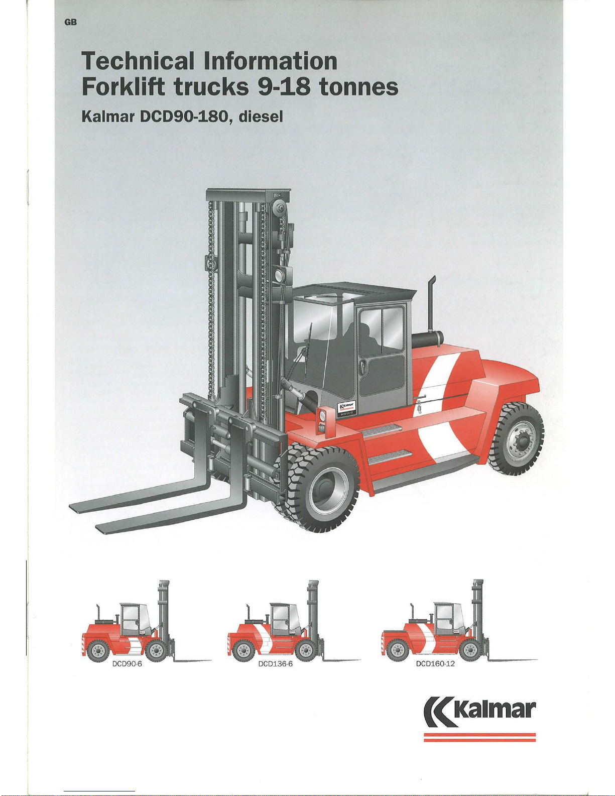
Technical Information
Forklift
trucks
9-18 tonnes
Kalmar DCD90-180, diesel
Page 2

l
Ka
lmar Industries
DCD90·180
The DCD90-180 with a lift
cap
acity
of
9-
18 tonnes
is the n
ew
generation
of
fo
rklift trucks in the medium segment
of
Kalmar's c
ompr
ehen sive range
of
4-
90 ton trucks - a well prov
en
range
of
tru
cks incorporating the latest design
so
lutions for o
ptimum productivity and
overa
ll
eco
nom
y.
A compr
ehe nsi
ve
range of o p tional
e
quipm
en t
pac
kages facilitat
es adaptation to sp ecial h andling environments
and
different typ es
of
goods.
Ty
pe designation:
DCD100·
12
Co
unter_-b
alan
ce
tru
ck
Dk
sel engine
::"_J
I T
Generation
---
- -
Lift
capacity, dec
itonnes
Load ce
ntr
e, decimetre
Opera
tor
Environment
The S
pir
it Delta cab is
of a co
mple
tely
n
ew
and mod e
rn des
ign that p rovid
es
th
e operator
with
an efficie
nt and
safe
place of wo rk.
Th
e design
of
the cab is
th
e result
of a co
mpr
eh ensi
ve
analysis
of
ope
rators ' working condition s
providing o
ptimum
visibility w it h large
glass areas and n o forward
corner p osts
to inhibit
th
e field of vision . The ins
tru
-
ment panel is gently ro
und
ed and ergo-
nomically designed
with
an
uninhibited clear
vi
ew
of a
ll
essential
informati
on. Access
to
the cab is
comfortable a
nd
secure thanks to the
thr
ee
ste p s
up
to th
e c
ab
and many well
located ha
nd
rails.
All cabs in th e seri
es can be tilted, for
op
timum
service
access. Noi
se
and
vibration levels are extr
emely l
ow
thank
s to the insulated mounting to the
ch assis. The tilting cylinders
ope
rate
against the
cab
whi
ch is isolated by
m
ea
ns
of
r ubb
er
elements.
The
ope
rator 's seat, steerin
g whe el and
hy
dr
aulic contr
ols are a
ll
individually
adjustable for
op
timum working
pos
ition. Two easily operated , ergonomically p osition ed multi-function l
eve
rs
are provid
ed for gear chang in
g,
wind-
scree
n wipers, washers a
nd horn
.
An
extremely
powe
rful h
eating/ve
ntila-
tio n unit e ns
ur
es a comfort
abl e cab
te
mp
erature. An easily replaced fre
sh
a
ir
filter cleans the incomin
g a
ir.
2
Technical Information DCD90-
180
Th
e unit sli
des
out to give easy access
for
se
rvice.
As
standard, t he e quipment
includ
es
a p
owe
rful
3-spee
d fan for
coo
lin
g, heat
ing, defrosting and recir-
culation.
O
pti
onal Extra
s:
• Extr
a h igh
cab
, +200
mm
• Elevated cab, + 300
mm
• Overhea
d g uard
• Roof mounted grid p rotection
• Co
mpl
ete
climate co
ntr
ol system
• Partially /fully rotatable
oper
ator se
at
Ins
trumenta
tion
Th
e instrument panel has logically
grou
pe
d units , a
ll
w ithin easy r each.
Sta
nd
ard ins
trument
ation includes
wa
rnin
g lamps for batte ry chargin
g,
l
ow
engine lubrication o
il
pressm e,
l
ow brake pressure, high
coo
lant
te m
pe
rature, high gearb
ox
oil tempera-
tur
e a
nd
applied parking brake.
In
add i-
tion, gauges display valu
es for engine
coolant
temperature, fu el quantity a
nd
op erating time .
Truc ks fitted w ith
ECS
mo nitorin
g are
not normally e
quipp
ed with wa
rnin
g
la
mp
s o r gauges. Th
ese functions are
handled by the
ECS
w hic h has a single
war
ning la
mp and
full text display
sh
ow
ing c urren t valu
es and
any faults
that
occ
ur.
Chassis
Th e chassis is built
of
fully welded ste
el
p ro
fil
es which g ives a rigid con
struc-
tion w
ith extr
emely strong mounting
po
int
s for the drive axle a
nd
lift equip-
ment.
S
tr
ess concentr ations have been elimi-
Jut
ed for o
ptimum
te nsile stren gth.
Th e chassis is flexible and is used
fo
r a
numb
er
of
differe nt drive line comb
ina-
tion s. The sp ace at the re
ar
of the
c
ha
ssis is used for count
er-weights, the
numb
er
of
w hich are adapted
to th
e
m
ac
hine in question.
Th e chassis
ha
s an
ext
rem e ly l
ow
profil
e for good visibilit
y.
Th e tanks are
separate
ly con
str
ucted and bolted to
th
e chassis in a position that al
so
co
ntribu
tes to good visibilit
y.
Page 3

Technical Information DCD90-180
Electrical System
The elect
rical system is logically struc-
tured, easily serviced a
nd
comp
letely
coordi
nat
ed
wit
h the
other
trucks
in
the
Kalmar range.
The
system
is
suppli
ed
by
two
12V batteries
connected
in
ser
ies c harged by
an alt
er-
nator,
with related electronics for recti-
ficati
on
and
current
stab
ilization.
The
system
provides
high
power
levels
even
at
low
engin e revs. Th e electrical
fuses, relays and
connectors
are
l
ocated
in
an
easily accessible
position
withi
n a
centra
l electrical unit inside
the
cab,
behind
the
operator
's seat.
KL898
Central electrica l unit
ECS (Optional)
· Electronic Control
System
Trucks can
be
equ
ipp
ed with
ECS,
a
sta
te
of
the
art
system for
optimum
operational security
and
overa
ll
eco
nomy.
The
systems consists
of
a
numb
er
of
modules that
can
be
combined
in different ways,
depending
on
the
nature
of
the
operations. For
examp
le,
the
foll
owing
function s are
ava
il
able:
• Automatic
gear
changing
(Load sensing system)
• Lever
steering
• Mini-steering
• Monitoring
• Electr
o-servo
See also
separate informati
on
about
the
Kalmar
ECS
System.
Engine
As
standard,
the
DCD90-180
truck
is
equipped
with
Volvo 's TD640VE diesel
engine and as
option
the
DCD90-136
with
the
Perkins 1006-60T1,
both
turbo-charged straig
ht
six diesel
engines
adapted
to
the
specialized
working requirements
of
a forkl ift
truck
, w i
th
high
power
and
torque
level
s,
even
at l
ow
engine
speeds. The
eng
ine has l
ow
exhaust
emission l
eve
ls
and
comp
lies
wit
h today's stringent
legal
enviro
nment
al
demands
(EU,
CARB,
EPA).
All engines
are characterized by l
ow
fuel consumpti
on
and l
ow
noise and
vibration levels.
Alternative engines:
• Perkins l 006-60T2
•
Volvo TD730VE
• Volvo TWD731VE
• Scania DI9
• C
ummins 6BTA
5.9-C200
See
Alternative drive lin
es
table
Transmission
Al
l trucks in
the
series
are
equipped
wit
h Clark's well
proven
hydro-
dynamic transmission systems
(3+3)
,
with integrated gea
rb
ox
and
torque
converter
, for
smooth, quick
acce
lera-
tion w
ith
a minimum
of
"clutch-slip".
A
number
of
different transmissi
ons
systems are ava ilable,
depending
on
the
sel
ected
engine
(see separate combin
a-
tion
table). Constant
mesh
gears and
gear
cha
nging by hydraulically
applied
clutches
(Powers
hift) are, h
owever
,
common
to all gearboxes.
Gear ch anging is el
ectrically achieved
via sol
enoid
valves,
with
three
reverse
and
three
forward gears,
controll
ed
by
means
of
an
easily
ope
rated multi-func-
tion lever.
Drive
axle
The
Kessler
D81
drive axle is
of
an
extreme
ly robust design to
be
able to
cope with
tough working environ-
ments
such
as
in
the
paper
and
pulp
industries, saw mills,
steel wo
rks,
ports
and terminals.
The
axle has reduction in
two
stages -
diff
ere
ntial and
hub
reduction -which
ensures
a minimum
of
strain
on
the
transmission system.
The
drive axle is
fitted w
ith
hydraulic braking system
(see
Servi
ce
Brake System).
Parking Brake System
The
parking brake system consists
of
a
dry
disc
brake
on
the
in-going shaft
of
the
drive axle. The disc brake
is
applied
by
means
of
a powerful spring in
the
parking
brake
cylind
er
and
is released
by
means
of
hydraulic
pressure
from
the
parking brake valve
in
the
cab.
Kalmar Industries
Volvo
TD640VE (6-cyl with turbo)
Service Brake System
The
service brake system
is
of
the
Wet
Disc Brake type, a system w
ith oil
-
coo
led discs
that
are alternate
ly
fixed
to
and rotating
with
the
hub.
When
the
brakes
are
app
li.ed,
the
discs are
pressed
together
by
hydraulic
pressure
from
the
brake pedal,
which provides
extremely effective braking.
The
system is v
irtually maintenance
free
and
can
cope
wit
h heavy l
oads
over
an
extended
period
of
time,
with
no fade
and
w i
thout
the
need
for
brake
adjust-
ments. The
heat
generated
durin
g
braking is dissipated via a
coo
ling
circ
uit
in w hi
ch
th e
truck
's total
volume
of
hydraulic fluid
comes
int
o
play. A
spec
ial filter
protects
the
braking system from any impmities.
Hub reduction
Kessler drive
axle
3
Page 4

Kalmar Industries
Load
diagramme
19
18
17
16
15
14
13
12
11
10
oco~aJ!BJ
1\.
ocoi6o.~(BJ
~
DC
D
160-9(B)
DCD
160-12 (B)
1\
r'\
f'
DCD
-
~
150-12
(B)
I
"\
"\
'
~
I'
~~
~
~
(A)
"'
~
~
~
~
~
1\.
~
'
"'~
DCD ......
~
"""
~
DCD120·6
(A)
1\.
120-12 (B)
~
"
'
"'
~
~
~
~
!oo..
DC D
~O().~
(A)
'
~
~
DCD100-L
(Al
['..
~
r
.......::
"'
<ll
9
c
c
B
8
z:.
'
(3
(I)
7
a.
(I)
0
o
co19().6
~
~
~
~
I'
~
.....
!'-
I"-
"
~
I'.
"""'
R
""'~
r-....
i'.
~
~~
.....
r--....
r--.
-
~
W)
c
6
;£?
::;
5
KL1073
600
900
1.200
1500 1800
2000
Load Centre, mm
A.
Perkins engine
B. Vol
vo
engine
1.
DCD
90·6
to DCD180·6 model
s:
Full lifting capacity
up
to
5000
mm
lift heig
ht wit
h Duplex/Duplex free-
lift
/T
riplex masts and integrated sidesh
ift/fork
positioning carriage.
4
Technical Information DCD90-
180
1 Model
Lifting capacity, deciton - Load centre distance, declmetre
A=
Perkins engine B = Volvo engine
2 Lifting capacity Rated
kg
!l
At max lifting height kg
..
...,
3 Lifting speed Unloaded
m
/s
'M
"'
At rated load
m/s
i2
4 Loweri
ng
speed
Un
loaded
m
/S
:J
At rated load
mjs
5 Driving speed forward/
Unloaded
km/ h
reverse
At rated load
km/h
.,
IJ
6 Gradient capability
Max, unloaded
%
c
..
Max
at
rated load %
E
.g
At 2
km/h
, unloaded
%
"
At 2
km/h,
at rated load %
D.
7 Draw bar pull
Max
kN
8 Stability
ISO
1.074/
10525
Yes/No
9 Service weight
kg
l:
10 Axle load front
Unloaded
kg
'M
At rated load
kg
-.;
~
1.1
Ax
le load back
Unloaded
kg
At rated load
kg
12
Engine
A.
Perkins B.
Volvo
Manufacturer- type designation
Fuel
· type
of
engine
Rating
ISO
3046 -at
revs [kW/ hp · rprr
Peak torque
I
SO
3046
·at
revs
Nm-rpm
e
.,
No of cylinders -
dis
placement cm
3
t>
,.,
Fuel consumption, normal operation
1/h
13
Alternator
Type- power
"'
w
.,
14
Starting battery Voltage -capacity
V-Ah
>
5
15
Gearbox
C.
Clark
20000
D. Clark
28000
Manufacturer · type
des
ignation
Clutc
h, type
Gearbox, type
No.
of
gears forward - reverse
16
Drive axle
Type
17
Wheels/ tyres
Type
front
and
rear
vi
Dimensions, front and rear/
Ply
inches,
.,
'!lO
numbe
D·e
No.
of
wheels, front - rear (* dnven)
_.,
Inflation pr
ess
ure
~$
MPa
::"'
18
Steering system
Ty
pe - maneuvering
.::
~
19
Service brake syst
em
Type
-affected wheels
20
Parking brake system
Type
-affected wheels
21
Hydraulic pressure Max MPa
0
22
Noise level DIN
45635
·36
Equivalent n
oise
level in cab (Lm) dB(A)
"'
~
23
Fuel volume L
24 Hydraulic
fluid volume L
25
Minimum
ais
le width for
90°
stacking with forks A1
mm
26
Tru
ck Truck length without for
ks
L
mm
Truck
width
B
mm
Height, basic machine
H6
mm
Seat height
H8
mm
Di
stance between centre of front L2
mm
axle - front face
of
fork
arm
Wheelbase L3
mm
Load centre L4
mm
Track
(c-c) front - rear
s
mm
Turning radius, outer
R1
mm
"'
Turning radius, inn
er
R2
mm
c
0
Ground clearance, min
·;;;
mm
c
Max height when tilting cab T1
.,
mm
E
Max width,
tilted
cab
T2
Ci
mm
27
Standard duplex
mast
Lifting height H4
mm
Mast
height, min.
H3
mm
Mas
t height. max.
H5
mm
Mast tilting, forwar
ds
-backwards
n·P
.
Grou
nd clearance, min mm
28
Forks
Width b
mm
Thickness
a
mm
Length
of
fork arms
I
mm
Width across fork arms, max v
mm
Width across fork arms, min
v
mm
Sideshift ±
at
width acr
oss
fork
arm
V1-V mm
This table relat
es
to trucks fitted with standard equipment,
for opti
onal equipment,
see separate tables.
1
l More powerful engines are available, up
to
167 kW/
230
hp
2
> Stronger gearboxes are available , Clark
32000
(3+3)
3
l
Semi-solid tyr
es
are available for all models (Super-Elastic)
We
reserve the right to alter design and material specifications, without pri
or noti
ce
Page 5

Page 6

L
Kalmar Industries
Steering System
The steering system is compl
etely
hydraulic
and
is
ted
from hydraulic
pump
1 (see the hydraulic system
diagram), via a priority valve.
Wh
en the
st
ee
ring
whee
l is
turned, th
e steering
v
al
ve transmits a load signal to the
priority val
ve
which
ensures
that
the
steering system always has sufficient
hydraulic
pr
essure.
Th
e steering axle
is
an
extremely
robust construction with double-action
cylinder.
Th
e pendulum suspension
of
the axle
over powerful,
spherical rubber
bear
-
ings has a lo
ng
operative lif
espan
and
pro
vides good shock-absorption .
The
minimal
numb
er of parts e nsures
oper
-
ational reliability, a minimum
of service
point
s and easy ma
int
enance. The
st
ee
ring
geometry
allows large
whe
el
displa
cement
and
thereb
y,
a tig
ht
tmning
circle.
Hydraulic System
Th
e hydraulic system includ
es the
following sub-systems:
• Working hydrauli
cs
• Service bral{e system
with braking
circuit and cooling circuit
• Parking brake sys
tem
• Hydraulic servo (standard)
• Steerin
g system
In standard form,
the
hydraulic system
is built a
round
two
gear
wheel
type
pump
s -
one
double and
one
single.
The pumps
are driven from the outlet
of
the torque
converter.
The flow
from
the pumps
is
feel
to a valve block
with
a
large
number
of
in-built f unctions (see
diagram). The valve block enabl
es
easy
installation
with
a minimum
number
of
hydraulic lin
es/hoses.
The
oute
r section
of the double
pump
feeds
the
lift
and
tilt functions, whil
st
the
inner
section
feeds
other
working
hydraulic function
s.
With fu
ll
exten-
sion
of the lift function, both
sec
tions
of
the
double
pump
operate
to provide
maximum
lift capa
city.
The
separate single
pump fee
ds
the
hydraulic accumulator,
which
in
turn
,
suppli
es the brake
and
servo systems.
As
a safety measure,
the
accumu
lator
ensures suffici
ent
brake pressure
to
be
able to
br
ake several times, should the
engine temporarily stop.
Th
e excess
flow
from
the
pump
s is l
ed
to the brake cooling circuit to dissipate
the he
at
generated during braking,
befo
re
being re
turned
to
the
hydraulic
tank.
Optional extras:
• Load sensing variable
pump
s
• Electro-servo controls
• Piston
type
accumul
ator
• Additional hydraulic functions
• Hydraulic joystick
6
Technical Information DCD90-180
Double-action
cylinde
r
Spherical
rubber bea ring
Steering
axle
1. Hydraulic
pu
mp, working
hyd
raulics,
steering system
2.
Hydraulic pump,
lift/t
ilt
3. Hydraulic pump, accumula tor charging
4. H1gh
pressure filter
5. High pressure filter
6. Main valve wi
th
double val
ve
block
a.
Accumulator
charge
valve
With fully charged accumulator feed to
brake
cooling circuit or return to tank
b.
Feed,
servo system
c.
Priority valve, steering syst
em
d.
Feed,
steering system
e.
Main pressure limitation val
ve
f. Contr
ol
valve,
LEVELLING
g .. Contr
ol
valve,
FORK
POSITIONING
h Contr
ol
valve,
SIDE-SHIFT
j.
Control valve,
TILT
k. Contr
ol
valve,
Ll
FT
m. Main pressure limitation valve
KL695
Hydra
ulic system
fo
r tru
ck
with Vol
vo
engine
7. Steering system
8.
Cooling circ
uit for servi
ce
brake system
9. Brake circuit, service brake system
10
.
Pa
rking brake system
11
. Accumulator
12.
Servo
assisted control levers
13.
Hyd
raulic tank
14.
Breather filter, hydraulic tank
Trucks
with
Perkins engines
are
equipped
with a simpl
er
hydr
aulic
system
with only
one
double
pump.
One
section
of the
pump
feeds
the
working hydrauli
cs
whilst
the
other
sect
ion fee
ds
the
steer
ing system a
nd
charges
the
accumulator.
The
main
va
lve is fitted
with
a valve block,
input
section and main pressure limitation
va
lve.
--
Page 7

Technical Information DCD90-
180
Lift
Mas
ts
All masts, b
ot
h d u p l
ex and tri
p lex, are
constructed
on
th e "free visibility p rin-
ciple"
and
can
be supplied with
the
area
steered
free-Lift
system whic
h, in
term
s of fun
ctio
n, is extr
eme
ly reliable
a
nd
secure.
The
rob
ust mast profil
es
are
of
high
tensil
e steel, di men sio ned fo r minimal
ob
struction
of
th e fie
ld
of
visio n a
nd
long servi
ce
life. Th e lift cylinde rs
are
pos
itio n
ed
in the "
dea
d " angl
es
of th e
mas
t.
All mast wh
ee
ls are harde ne d a
nd
fitted with high q uality bearings.
As
standard, trucks are fitte d w ith the
dup l
ex free
visibility mast.
Optional extras:
• Dupl
ex
free visib
ili
ty m
ast
w it h
free-lift
• Trip l
ex free
visibili
ty
mast wi
th
free-lift
Duplex free
visibility mast
Dupl
ex
free
visibility
mast
with
free·
lift
Triplex free
visibi li
ty
mast
wi
th
free·
lift
90·136,
two free·
lift
cylinders
(150-180,
one
ce
ntr
al free-l
ift
cylinder)
Fork Carriages
A nu mb e r
of
different models
of
fork
carr
iages are available, a
ll
of
them
wit
h
excellent th
roug
h-vision. T h e stan dard
mode
l has ma nu ally
moveab
le forks.
Howev
er,
the
majority
of
trucks are
suppli
ed
with hydraulic side-shift a nd
fork
posi
tioning.
Option al extras:
• For k
pos
itionin
g/s
ide-shift
• Fo rk
pos
itionin
g/side-shift w i
th
levelling
• Fork
pos
itio nin
g/s
ide-shift w ith
ce
nt re levelling
• Side-s hi ft ca
rri
age
•
Fork shaft system
• Ad di tional types
of
clamp
attachments
• Coil rams fo r
steel han
dling
Side-
shift
carriage
F
orks
Th e forks
are
one-pi
ece
for
ged
in
hig h
tens
ile stee
l.
Th e standard fitti ng is
over
hooks o n the fork carriage , w hil st
hydraulically co
ntroll
ed forks are fitt ed
ove
r rollers
runnin
g on bearings - fo
ur
up
per roll
ers a
nd
two lower suppo
rt
fo r
each fo
rk.
For
ease
of
changing bet
ween fo
rks and
other attachments, a fork sh aft system
is available , w h
ere
the forks
are
mounte
d on a separate fo rk ho lder.
1.
Standard forks
for
manual
manoeuvring
2. Forks with
roller
fittings for hydraulic
manoeuvring
3.
Fo
rk shaft system
with separate
ho
lder
for each fork
4.
Forks with
hydraulic levelling
3
Kalmar Industries
Lift
Uft
Lift mast
Free
· Lift mast
Free-
mast
heigl'lt
heig
ht
lift
height
lift
Min Max
Min
Max
H4
1)
H3
1)
H5
H2
H3 H5
H2
mm
mm
mm mm
mm
mm mm
90
·6-
136
-6
100-1 2-
180
-6
Dupl
ex
3000 3000
4500
-
3185 4685
-
fr
ee
3250
3125 4750
-
3310
4935
-
vis
i-
bility
3500 3250 5000
-
3435
5185
-
3750 3375 5250
-
3560 5435 -
4000 3500 5500
-
3685 5685
-
4250 3625 5750 - 3810
5935 -
4500 3750
6000
-
3935 6185 -
4750 3875
6250
-
4060
6435
-
5000
4000
6500
-
4185 6685 -
5250 4125 6750
-
4310 6935 -
5500 4250 7000 - 4435 7185
-
5750 4375 7250 - 4560 7435
-
6000
4500 7500
-
4685 7685
-
6250
4625 7750
-
4810
7935
-
6500
4750
8000
-
4935
8185
-
6750 4875 8250 - 5060
8435
-
7000 5000 8500 - 5185
8685
-
Duplex
3000
3000 4500 1500 3175 4675 1500
fr
ee
3250 3125
4750
1625 3300
4925
1625
vi
si-
bility,
3500 3250 5000 1750 3425 5175 1750
fr
ee-
3750 3375 5250 1875 3550 5425 1875
lift
4000 3500 5500 2000 3675 5675 2000
4250 3625 5750 2125 3800 5925 2125
4500 3750
6000
2250 3925 6175 2250
4750
3875 6250 2375
4060
6425 2375
5000 4000 6500 2500 4175 6675 2500
5250 4125 6750 2625 4300 6925 2625
5500 4250 7000 2750 4425 7175 2750
5750 4375
7250
2875 4550
7425 2875
6000
4500 7500
3000
4675 7675
3000
6250 4625 7750 3125 4800 7925 3125
6500 4750
8000
3250 4925
8175
3250
6750 4875
8250
3375 5050
8425
3375
7000 5000
8500
3500 5175 8675 3500
Triplex, 4500 2940 5940 1500 3120
6180
1500
free
4750
3025
6190
1580
3205
6435
1580
vis~
bility
,
5000
3110 6440 1665 3285
6685
1665
fr
ee-
5250 3195 6690 1750
3370
6930
1750
lift
55
00
3280 6940 1830 3450 7180 1830
5750 3360 7190 1915 3535 7435 1915
6000 3445 7440 2000 3615 7685 2000
6250 3530 7690 2080
3700 7940
2080
6500
3615
7940
21
65
3780
8180
2165
6750 3700
8190 2250
3865
8435
2250
7000 3780 8440 2340 3945
8685
2340
1)
These figures are based on the 1
20·6
and
va~
wi
th
tyre dimen sions. H3 and H5 alter
-
1 mm for
90-100
·6
+20
mm for 1
36-6
:!"
Ia
~
I
~):1,
2
........
~
f
•
~
..
~
.......
·t:
~
,
~
4
l i
~
~
l
""'
~
......
~
7
Page 8

Kalmar Industries
Service Access
Ro
utin
e daily service
checks
cont
ribu
te
to
a safer
work
place and reduce the
risk
of break
-downs.
Daily servi
ce che
cks are
made
easier
thanks to well
thought out and
grouped servi
ce
points. The
ope
rator
can r
eac
h a
ll
servi
ce
points without
having to climb
up onto the
truck
.
The
cab can
be
tilted
by
means
of
a
hydrauUc cylind
er
ope
rated
by
a
manual
pump. When
the
cab has been
tilted, the
gearbox, hydraulic
pumps
,
hyclrauUc fluid fil ter, parking brake,
main
va
lves, control valves, etc., are
readily accessible for servi
ce
.
The
eng
ine ho
od
is divided into
thr
ee
sect
ions - a fixed middle
section
that
bears
the silencer
and
hinged out
er
sect
ions to
each si
de.
1.
Indicator for air filter
2. Gearbox
oil, dip-stick and filler cap
3. Engine
oil, dip-stick and filler cap
4.
Coolant
5. Screen wash liquid
6.
Fuel,
filler cap
7. Main switch,
electrical system
8. Batteries 2x12 V -
140
Ah
Truck with overhead guard.
I
CRTRRCOM
INV
z:,~EENG
E
3M3~"EG
7 Tel. +32 {0)3 541
77
22
••
• Fax +32 (0)3
541
28 23
2030 ANTWERP
EN-
3 E-mail info@catracom.
be
BELGI
UM
www.catracom.com
Technical Informati
on
DCD90-
180
Standard equipment
The
standard
spec
ifi
cati
on
of
our
trucks includes
imp
ortant
and
vital
co
mponents that
con
tribute
to
the
effi-
cien cy and safety
of
the
truck.
• Robu
st
truck
chassis 9-18 ton
• Spir
it
Delta operator environ
ment
w ith l
ow
noise level
•
Til
table
cab
insulated again
st
vibration
• P
owe
rful
ven
tilation
unit
wit
h effi-
cient
filt
er
• Roof
window
of lexa
n
• Sliding w
ind
ow
on
the
left hand side
•
Wash/wipers
, front, r
ear
and
roof
• Lockable
cab
doors
· •
Wiele
bottom
access
step and
two
extra
steps
on
both
sid
es
Adjustable,
shock
absorbing, e rgo-
nomic
operator
seat w ith safety b elt
• Three-way adjustable
stee
ring console
• Two-way adjustable hydraulic lever
conso
le
•
Ann support
on right
hand
side
• Environme
nt
friendly powerful engines
• Fully dim
ensioned
radi
ator for
engine
and
oil
cooler
for gearbox
• Powerful gearboxes
with
powershift
• Drive axle with o
il
coo
led
eli
se brakes
• Free visibility lift equipm
ent
• Steering axle
with
double-action cyl-
ind
er
• Hydraulic system with finger tip control
• Simple, reliab
le electrical system
• Co
mpr
ehe nsive and logically
gro
up
ed instrumentation
• Accelerator, brake
pedal
and
forward-
reverse selector
• Lig
htin
g:
Working ligh ts, indicators,
brake, reversing and
pos
itional lights
• Large servi
ce hatc
hes and tiltable cab
for daily i
nspections
• Towing p in (manual)
•
Comp
lete
documentation
Alternative drive lines
e = Standard 0 = Optional
En
gine *Turbo **Turbo, intercooler
Volvo
TD640VE*
129
kW/690
Nm
Perkins 1006-60T1 •
85
kW I 465
Nm
Volvo TD730VE*
15
0 kW/800
Nm
Volvo
TW0731VE
**
1
67
kW/893
Nm
Perkins 1006·60T2*
114
kW/620
Nm
Scan
ia
019
**
1
67 kW/930
Nm
Cummins
6BTA5.9-C200
**
162 kW/814
Nm
Gearbox wi
th
powershift,
3+3
gears
Cl
ark
13.
7HR
28000
(Volvo
TD640VE, TD730VE,
Perk
ins 1006·60T2, Cummins
6BTA)
Cl
ark
1207
FT
20302
(Perkins 1
006
·60T1)
Cl
ark
13.
7HR
32000
(Vo
lvo TD640VE,
TD730VE.
Volvo
TWD731VE,
Scania
01
9, Cummins
6BTA)
Drive axle wi
th
Wet
Disc Brakes
Pn
eumatic tyres
10.00x20"/16
PR
11.00x20"/16
PR
12
.00x20' '/20PR
Optional: Semi
-so
lid tyres (Super-Elastic)
Safety
A
ll Kalm
ar
trucks are CE-marke
cl
and
are con
structed to
and
comp
ly w
ith
the
followin
g norms:
•
EN1551
•
ASME
B56.1
(USA,
trucks
up
to
13.6
tonnes)
• EN12895 (EMC
test
, Europe)
Optional equipment
A
wide
range
of
optional eq
uipm
ent
and packages are available for
our
trucks, to satisfy furt
her
spec
ializa
tion
and provide added efficiency
• Alternative
engines
and
gearboxes
• Load sen sing hydraulic syst
em
• Exterior and interior
cab equi
pment,
such
as air
cond
itioning,
etc
.
• Lighting, mirrors
and
protective
grid
• Different types
of
lift equipm
ent,
at-
tachments
, ex
hau
st contr
ols, air
fil-
ters, etc.
•
ECS
wit
h different types
of
module
• Catalytic
converte
r and particle filter
Summary
Ka
lmar's
medium
trucks
are
of a we
ll
proven
design, ma
nuf
actured in large
volumes for demanding en
vironm
ents
su
ch
as:
• Timber,
paper
and
pulp
indu
stries
• Steel
wor
ks and foundries
•
Concrete
industry
• Ports
and
terminals
•
Other
heavy industri
es
A well
planned
and
protected
operator
envi1'onment mak es Kalmar's trucks
efficie
nt
and comf
ortable
wor
king
implements.
R
ea
dily
acce
ssible set·vi
ce
points for
ease
of
maintenance.
•
•
• • • • •
• • • •
0 0 0 0 0
0 0 0 0 0 0 0 0 0
0
0 0 0 0 0 0 0 0 0 0
0 0 0 0 0 0 0 0 0
0
0
0 0 0 0 0 0 0 0
0 0 0 0 0 0 0 0 0 0 0
• •
•
•
•
• •
• •
• •
0 0 0 0 0
0 0 0 0 0 0 0 0 0 0
0
•
•
• • • • • • • • •
• •
•
• • • • • •
•
•
0 0 0 0 0 0 0 0 0 0 0
. almar Industries Sverige AB
E-341
81
Ljungby, Sweden
Kalmar Industries
Oy
Ab
P.O. Box
387
Kalmar Industries USA Inc •
415
East Dundee Street
Ottawa,
Kan
sas
66067, USA
Tel.
+1
785
242
2200
31.
+46
372
260
00
ax +46
372
263
90
FIN-331 01 Tampere, Finland
Tel.
+358 3 265
8111
Fax
+358 3 265
8201
Fax
+1
785
242
6117
A Partek Company
 Loading...