


COMPACT COMPONENT MD SYSTEM
SISTEMAS MD DE COMPONENTES COMPACTOS SISTEMA MD DE COMPONENTE COMPACTO
CA-MD70
MD |
PLAY |
|
|
TITLE |
|
|
|
INPUT |
MODE |
|
|
MARK |
ABC |
DEF |
SLEEP |
1 |
2 |
3 |
|
|
|
|
DISPLAY |
GHI |
JKL |
MNO |
/CHARA |
4 |
5 |
6 |
|
PQRS |
TUV |
WXYZ |
CANCEL |
7 |
8 |
9 |
|
|
|
|
SET |
10 |
0 |
+10 |
|
FM MODE |
SOUND |
BASS |
ENTER |
FM/AM |
TAPE |
AUX |
CD3 |
MD |
MD |
|
CD2 |
REC PAUSE |
|
||
FADE MUTING |
CD |
|
CD1 |
|
REPEAT |
|
|
VOLUME |
|
|
|
REMOTE CONTROL |
RM-SEM70EU |
||
COMPACT
DIGITAL AUDIO
INSTRUCTIONS
MANUAL DE INSTRUCCIONES
INSTRUÇÕES |
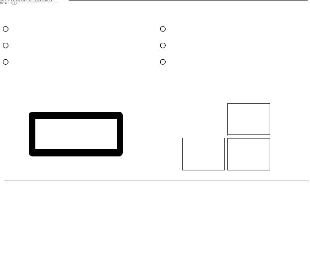
For Customer Use: |
||
|
|
Enter below the Model No. and Serial |
|
|
|
No. which are located either on the rear, |
|
|
|
bottom or side of the cabinet. Retain this |
|
|
|
information for future reference. |
|
|
|
Model No. |
|
|
|
|
|
|
|
Serial No. |
|
|
|
|
|
|
|
LVT0075-001B |
|
[ U, UT, US, UB ]
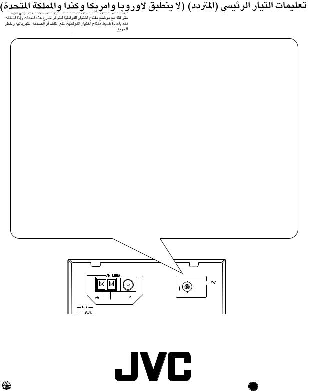
Mains (AC) Line Instruction (not applicable for Europe, U.S.A., Canada, and U.K.)
Instrucción sobre la línea de la red (CA) (no aplicable para Europa, EE.UU., Canadá, ni el Grã-Bretanha)
Instrução sobre a tensão da rede eléctrica (CA) (não aplicável para a Europa, os E.U.A., o Canadá, e o Reino Unido)
IMPORTANT for mains (AC) line
BEFORE PLUGGING IN, do check that your mains (AC) line voltage corresponds with the position of the voltage selector switch provided on the outside of this equipment and, if different, reset the voltage selector switch, to prevent from a damage or risk of fire/electric shock.
IMPORTANTE para la línea de la red (CA)
ANTES DE ENCHUFAR EL EQUIPO, compruebe si la tensión de la línea de la red (CA) corresponde con la posición del selector de tensión situado en la parte exterior del equipo, y si es diferente, reajuste el selector de tensión para evitar el riesgo de incendios/ descargas eléctricas.
IMPORTANTE para a ligação à tensão da rede (CA)
ANTES DE LIGAR O APARELHO A UMA TOMADA DA REDE, verifique se a tensão da rede CA corresponde à posição do seletor de voltagem localizado na parte externa deste equipamento. Caso não corresponda, reajuste o seletor de voltagem a fim de evitar avarias ou riscos de incêndio e choque elétrico.
220V
LINE VOLTS
|
|
230 – |
110V |
GND |
AM EXT |
240V |
127V |
FM |
|
||
|
AM |
75 |
|
|
LOOP |
COAXIAL |
|
EN, SP, PR, CH, AR |
VICTOR COMPANY OF JAPAN, LIMITED |
J C 1198JTMMDWJEM |
|
|
V |
Warnings, Cautions and Others Avisos, precauciones y otras notas Advertências, precauções e outras notas
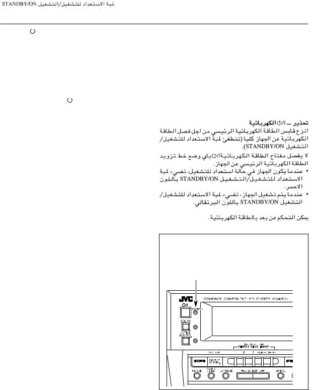
Caution ––
 switch!
Disconnect the mains plug to shut the power off completely (the STANDBY/ON lamp goes off).
The  switch in any position does not disconnect the mains line.
•When the unit is on standby, the STANDBY/ON lamp lights red.
•When the unit is turned on, the STANDBY/ON lamp lights orange.
The power can be remote controlled.
Precaución –– Interruptor 
 !
!
Desconecte el enchufe de la red para desconectar la alimentación por completo (la lámpara STANDBY/ON se apaga).
El interruptor  no desconectará completamente la alimentación principal, cualquiera que sea su posición.
•Cuando la unidad está en espera, la lámpara STANDBY/ON se enciende en rojo.
•Cuando conecta la unidad, la lámpara STANDBY/ON se enciende en naranja.
La alimentacion puede ser controlada a distancia.
Precaução –– Interruptor !
!
Desconecte o cabo de alimentação para desligar completamente a alimentação de energia (o indicador luminoso STANDBY/ON se apaga).
O interruptor  não desconecta totalmente a alimentação seja qual for a sua posição.
•Quando o aparelho estiver em standby, o indicador luminoso estará vermelho.
•Quando o aparelho estiver ligado, o indicador luminoso estará laranja.
A alimentação pode ser controlada remotamente.
The STANDBY/ON lamp |
Lámpara STANDBY/ON |
Indicador luminoso STANDBY/ON |
– G-1 –
CAUTION
To reduce the risk of electrical shocks, fire, etc.:
1.Do not remove screws, covers or cabinet.
2.Do not expose this appliance to rain or moisture.
PRECAUCIÓN
Para reducir riesgos de choques eléctricos, incendio, etc.:
1.No extraiga los tornillos, los cubiertas ni la caja.
2.No exponga este aparato a la lluvia o a la humedad.
PRECAUÇÃO
Para reduzir riscos de choques elétricos, incêndio, etc.:
1.Não remova parafusos e tampas ou desmonte a caixa.
2.Não exponha este aparelho à chuva nem à umidade.
– G-2 –
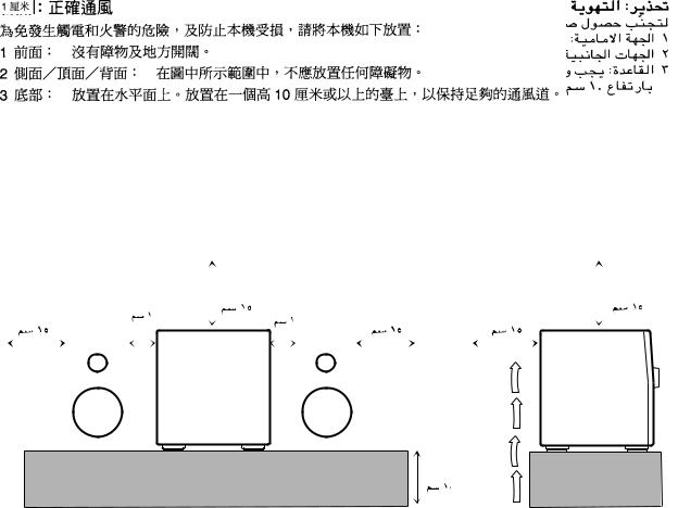
Caution: Proper Ventilation
To avoid risk of electric shock and fire, and to prevent damage, locate the apparatus as follows:
1 |
Front: |
No obstructions and open spacing. |
2 |
Sides/ Top/ Back: |
No obstructions should be placed in the areas shown by the dimensions below. |
3 |
Bottom: |
Place on the level surface. Maintain an adequate air path for ventilation by placing on a stand |
|
|
with a height of 10 cm or more. |
Precaución: el aparato debe estar bien ventilado
Para evitar posibles riesgos de descargas eléctricas e incendios y prevenir cualquier posible daño, coloque el aparato del modo siguiente:
1 |
Parte delantera: |
No ponga nada delante, deje el espacio libre. |
2 |
Laterales/ parte superior/ parte trasera: No se debería colocar nada en las áreas y las distancias que se |
|
|
|
detallan a continuación. |
3 |
Parte inferior: |
Coloque el aparato sobre una superficie recta. Debe haber buena circulación de aire; para |
|
|
ello, coloque el aparato sobre una base a una altura mínima de 10 cm. |
Precaução: Ventilação adequada
Para evitar riscos de choques elétricos e incêndios, e prevenir avarias, instale o aparelho como segue:
1 |
Parte frontal: |
Sem obstruções e espaços abertos. |
2 |
Partes laterais/Tampa/Posterior: Nenhuma obstrução deverá ser colocada entre as áreas cujas dimensões são |
|
|
|
indicadas abaixo. |
3 |
Parte inferior: |
Instale-o sobre uma superfície plana. Deverá ser mantido espaço suficiente para a ventilação |
|
|
se este for instalado numa posição que tenha uma altura de 10 cm ou mais. |
|
|
|
|
|
1 cm |
|
|
15 cm |
|
|
|
|
|
|
|
|
|
|
|
|
|
|
15 cm |
||||
|
|
|
|
|
|
|
15 cm |
1 cm |
15 cm |
15 cm |
|||||||||||||||||
15 cm |
|
|
|
|
|
|
|
|
|
|
15 cm |
|
|
||||||||||||||
|
|
|
|
|
1 cm |
|
|
|
|
|
|
|
|
|
|
|
|
|
|
|
|||||||
|
|
|
|
|
|
|
|
|
1 cm |
|
|
|
|
|
|
|
|||||||||||
|
|
|
|
|
|
|
|
|
|
|
|
|
|
|
|
|
|
|
|
|
|
|
|
|
|
|
|
|
|
|
|
|
|
|
|
|
|
|
|
|
|
|
|
|
|
15 cm |
|
|
15 cm |
||||||
|
|
|
|
|
|
|
|
|
|
|
|
|
|
|
|
||||||||||||
15 cm |
|
|
|
|
|
|
|
|
|
|
|
|
|
||||||||||||||
|
|
|
|
|
|
|
|
|
|
|
|
|
|
|
|
|
|
|
|
|
|
|
|
|
|
|
|
|
|
|
|
|
|
|
|
|
|
|
|
|
|
|
|
|
|
|
|
|
|
|
|
|
|||
|
|
|
|
|
|
|
|
|
CA-D3S |
|
|
|
|
|
|
|
|
|
|
|
|
|
|
CA-D3S |
|
||
|
|
|
|
|
|
|
|
|
CA-MD70 |
|
|
|
|
|
|
|
|
|
|
|
|
|
|
CA-MD70 |
|
||
|
|
|
|
|
|
|
|
|
|
|
|
|
|
|
|
|
|
|
|
|
|
|
|
|
|
|
|
|
|
|
|
|
|
|
|
|
|
|
|
|
|
|
|
|
|
|
|
|
|
|
|
|
|
|
|
|
|
|
|
|
|
|
|
|
|
|
|
|
|
|
|
|
|
|
|
|
|
|
|
|
|
|
|
10 cm
10 cm
– G-3 –
IMPORTANT FOR LASER PRODUCTS / IMPORTANTE PARA PRODUCTOS LÁSER / IMPOTANTE PARA PRODUTOS LASER /  /
/ 
REPRODUCTION OF LABELS / REPRODUCCIÓN DE ETIQUETAS / REPRODUÇÃO DE ETIQUETAS / 
1 |
CLASSIFICATION LABEL, PLACED ON REAR ENCLO- |
2 |
WARNING LABEL, PLACED INSIDE THE UNIT |
||||
|
SURE |
|
|
|
|
||
1 |
ETIQUETA DE CLASIFICACIÓN, PEGADA EN LA PARTE |
2 |
ETIQUETA DE ADVERTENCIA, PEGADA EN EL INTE- |
||||
|
POSTERIOR DE LA CAJA |
|
RIOR DE LA UNIDAD |
||||
1 |
ETIQUETA DE CLASSIFICAÇÃO LOCALIZADA NA PARTE |
2 |
ETIQUETA DE ADVERTÊNCIA LOCALIZADA NA PARTE |
||||
|
POSTERIOR DA CAIXA DO APARELHO. |
|
INTERNA DA UNIDADE. |
||||
|
|
|
|
|
|
|
|
|
|
|
|
|
|
|
|
|
|
|
|
|
|
|
|
|
|
|
|
|
|
|
|
CLASS 1
LASER PRODUCT
DANGER: |
Invisible |
laser |
radiation |
when open |
and |
interlock failed or defeated. |
||
AVOID DIRECT EXPOSURE |
||
TO BEAM. |
|
(e) |
|
|
|
|
|
|
ADVARSEL: Usynlig |
laser- |
|
stråling ved åbning, |
når |
|
sikkerhedsafbrydere er ude af funktion. Undgå udsættelse for stråling (d)
VARNING: Osynlig laserstrålning när denna del är öppnad och spärren är urkopplad. Betrakta ej strålen. (s)
VARO: Avattaessa ja suojalukitus ohitettaessa olet alttiina näkymättömälle lasersäteilylle. Älä katso säteeseen. (f)
1.CLASS 1 LASER PRODUCT
2.DANGER: Invisible laser radiation when open and interlock failed or defeated. Avoid direct exposure to beam.
3.CAUTION: Do not open the top cover. There are no user serviceable parts inside the Unit; leave all servicing to qualified service personnel.
1.PRODUCTO LÁSER CLASE 1
2.PELIGRO: En el interior hay radiación láser invisible. Evite el contacto directo con el haz.
3.PRECAUCIÓN : No abra la tapa superior. En el interior de la unidad no existen piezas reparables por el usuario; deje todo servicio técnico en manos de personal calificado.
1.PRODUTO LASER CLASSE 1
2.PERIGO: O laser emite uma rediação invisível que é perigosa, caso o aparelho esteja aberto e a trava inoperante ou danificada. Evite exposição direta ao feixe dos raios.
3.CUIDADO: Não abra a caixa do aparelho. Não existem peças reparáveis pelo usuário na parte interna da unidade.
Solicite assistência técnica somente a pessoal técnico qualificado.
– G-4 –
English
Introduction
We would like to thank you for purchasing one of our JVC products. Before operating this unit, read this manual carefully and thoroughly to obtain the best possible performance from your unit, and retain this manual for future reference.
About This Manual
This manual is organized as follows:
•The manual mainly explains operations using the buttons and controls on the unit. You can also use the buttons on the remote control if they have the same or similar names (or marks) as those on the unit.
If operation using the remote control is different from that using the unit, it is then explained.
•Basic and common information that is the same for many functions is grouped in one place, and is not repeated in each procedure. For instance, we do not repeat the information about turning on/off the unit, setting the volume, changing the sound effects, and others, which are explained in the section “Basic Settings” and “Common Operations” on pages 10, 11, and 12.
•The following marks are used in this manual:
Gives you warnings and cautions to prevent from a damage or risk of fire/electric shock.
Also gives you information which is not good for obtaining the best possible performance from the unit.
Gives you information and hints you had better know.
Precautions
Installation
•Install in a place which is level, dry and neither too hot nor too cold — between 5˚C and 35˚C.
•Install the unit in a location with adequate ventilation to prevent internal heat built-up in the unit.
•Leave sufficient distance between the unit and the TV.
•Keep the speakers away from the TV to avoid interference with TV.
DO NOT install the unit in a location near heat 
 sources, or in a place subject to direct sunlight,
excessive dust or vibration.
Power sources
• When unplugging from the wall outlet, always pull the plug, not the AC power cord.
DO NOT handle the AC power cord with wet hands.
Moisture condensation
Moisture may condense on the lens inside the unit in the following cases:
•After starting heating in the room
•In a damp room
•If the unit is brought directly from a cold to a warm
place
Should this occur, the unit may malfunction. In this case, leave the unit turned on for a few hours until the moisture evaporates, unplug the AC power cord, and then plug it in again.
Others
•Should any metallic object or liquid fall into the unit, unplug the unit and consult your dealer before operating any further.
•If you are not going to operate the unit for an extended period of time, unplug the AC power cord from the wall outlet.
DO NOT disassemble the unit since there are no user serviceable parts inside.
If anything goes wrong, unplug the AC power cord and consult your dealer.
– 1 –

Contents
Location of the Buttons and Controls ........... |
3 |
Front Panel ............................................................. |
4 |
Remote Control ...................................................... |
5 |
Getting Started ................................................ |
6 |
Unpacking .............................................................. |
6 |
Putting the Batteries into the Remote Control ....... |
6 |
Connecting Antennas ............................................. |
6 |
Connecting Speakers .............................................. |
7 |
Connecting Other Equipment ................................ |
8 |
Adjusting the Voltage Selector ............................... |
9 |
Basic Settings ................................................ |
10 |
Setting the Clock .................................................. |
10 |
Changing the Display Pattern .............................. |
10 |
Recording onto an MD ................................. |
23 |
Things to Know Before You Start Recording ...... |
23 |
Recording FM/AM Broadcasts or from the |
|
Cassette Deck ................................................ |
24 |
Recording from the External (AUX) Equipment ... |
25 |
Recording CDs ..................................................... |
26 |
Editing MDs .................................................. |
28 |
Introducing MD Editing Functions ...................... |
28 |
DIVIDE Function ................................................ |
29 |
JOIN Function ...................................................... |
30 |
MOVE Function ................................................... |
31 |
ERASE Function .................................................. |
32 |
ALL ERASE Function ......................................... |
33 |
Erasing a Portion of a Track ................................ |
33 |
Common Operations .................................... |
11 |
Turning On the Power and Selecting the Sources |
.. 11 |
Adjusting the Volume ........................................... |
11 |
Reinforcing the Bass Sound ................................. |
12 |
Selecting the Sound Modes .................................. |
12 |
Creating Your Own Sound Mode — MANUAL |
|
Mode .............................................................. |
12 |
Listening to FM and AM Broadcasts .......... |
13 |
Setting the AM Tuner Interval Spacing ................ |
13 |
Tuning in a Station ............................................... |
13 |
Presetting Stations ................................................ |
14 |
Tuning in a Preset Station .................................... |
14 |
Playing Back CDs ......................................... |
15 |
Loading CDs ........................................................ |
15 |
Playing Back the Entire Discs |
|
— Continuous Play ........................................ |
16 |
Basic CD Operations ........................................... |
16 |
Programming the Playing Order of the Tracks |
|
— Program Play ............................................ |
16 |
Playing at Random — Random Play ................... |
18 |
Repeating Tracks or CDs — Repeat Play ............ |
18 |
Prohibiting Disc Ejection — Disc Lock .............. |
18 |
Playing Back an MD ..................................... |
19 |
Playing Back the Entire MD |
|
— Continuous Play ........................................ |
19 |
Basic MD Operations ........................................... |
19 |
Programming the Playing Order of the Tracks |
|
— Program Play ............................................ |
20 |
Playing at Random — Random Play ................... |
22 |
Repeating Tracks — Repeat Play ........................ |
22 |
Assigning Titles to MDs ................................ |
34 |
Assigning a Title Using the Unit .......................... |
34 |
Assigning a Title Using the Remote Control ....... |
37 |
Using the Timers ........................................... |
39 |
Using Recording Timer ........................................ |
39 |
Using Daily Timer ............................................... |
40 |
Using Sleep Timer ............................................... |
42 |
Timer Priority ....................................................... |
42 |
Maintenance .................................................. |
43 |
Additional Information ................................ |
44 |
MD Disc Types .................................................... |
44 |
ATRAC (Adaptive TRansform Acoustic Coding) .. |
44 |
UTOC (User Table Of Contents) ......................... |
44 |
SCMS (Serial Copy Management System) .......... |
44 |
Sound Skip Guard Memory ................................. |
45 |
Troubleshooting ............................................ |
46 |
MD Messages ...................................................... |
47 |
Specifications ................................................. |
48 |
English
– 2 –

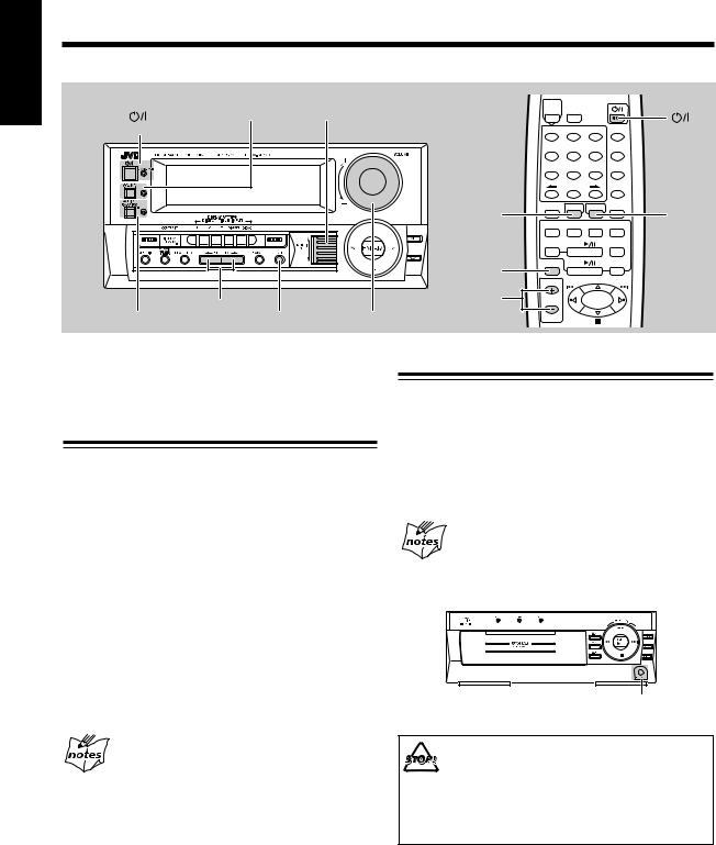
English
Location of the Buttons and Controls
Become familiar with the buttons and controls on your unit.
Front Panel
Amplifier/ tuner section
MD recorder section
CD player section
|
p |
|
1 |
q |
|
|
||
2 |
w |
|
e |
||
3 |
||
r |
||
4 |
||
t |
||
5 |
||
y |
||
6 |
||
u |
||
7 |
||
i |
||
8 |
||
o |
||
9 |
||
d |
||
; |
||
|
||
a |
f |
|
s |
||
|
g
|
k |
h |
|
j |
l |
/
z
Display Window
1 |
2 |
3 |
4 |
|
5 |
||||||||
|
|
|
|
|
|
|
|
|
|
|
|
|
|
|
|
|
|
|
|
|
|
|
|
|
|
|
|
|
|
|
|
|
|
|
|
|
|
|
|
|
|
|
|
|
|
|
|
|
|
|
|
|
|
|
|
|
|
|
|
|
|
|
|
|
|
|
|
|
|
|
|
|
|
|
|
|
|
|
|
|
|
|
|
|
|
|
|
|
|
|
|
|
|
|
|
|
|
– 3 –
Continued
See pages in the parentheses for details.
Front Panel
Amplifier/tuner section
1  button and STANDBY/ON lamp (11)
2 SOUND button and lamp (12)
3 ACTIVE BASS EX. (extension) button and lamp (12)
4 CONTRAST/DISPLAY/CHARA. (character) button (10, 20, 34)
5 TITLE button (34)
6 MD EDIT button (29)
7 CLOCK/TIMER button (10, 39)
8 PLAY MODE button (16, 18, 20, 22)
9 CURSOR ø/ Øbuttons (12, 35)
pDISPLAY PATTERN buttons (10)
•1, 2, 3, DIMMER, and DEMO buttons
Pressing DEMO also turns on the unit.
DIRECT TITLE INPUT buttons (35) q Display window
w VOLUME control (11) e ENTER button (35) r MULTI JOG dial
t TAPE button (11)
Pressing this button also turns on the unit. y Tuner control buttons (13)
• FM/AM, + / –, and < / > buttons
Pressing FM/AM also turns on the unit. u AUX button (11, 25)
Pressing this button also turns on the unit. i SET button
o CANCEL button
MD recorder section
;MD recorder operation lamps
•MD IN, REC, and DIGITAL lamps a 0(eject) button (19)
Pressing this button also turns on the unit. s MD loading slot
d SENSOR (remote sensor) f MD CONTROL buttons (19)
•MD 6, REPEAT, 4/ ¢, and 7buttons
Pressing MD 6also turns on the unit.
gRecording buttons (24 – 27)
•CD REC, REC PAUSE, 1ST TRACK REC, and LISTENING buttons
CD player section
hDisc number lamps
•CD 1, CD 2, and CD 3 lamps j Disc compartment
k CD CONTROL buttons (15)
•CD 6, REPEAT, 4/ ¢, and 7buttons
Pressing CD 6also turns on the unit.
lDisc number buttons (16)
• CD 1, CD 2, and CD 3 buttons
Pressing one of these buttons also turns on the unit.
/0(open/close) buttons (15)
•01, 02, and 03 buttons
Pressing one of these buttons also turns on the unit.
z PHONES jack (11)
Display window
1 Main display
2MD/CD playback mode indicators
•PROGRAM, RANDOM, REPEAT mode indicators 3 Timer mode indicators
•DAILY (daily timer) and REC (recording timer) indicators
4 STEREO indicator
5 Analog clock
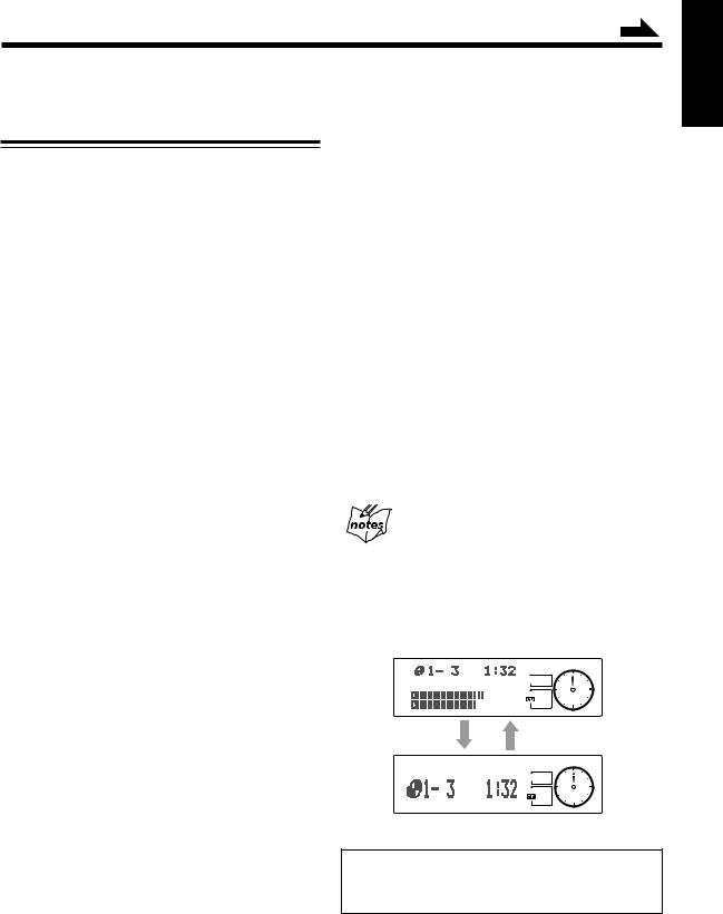
About the indications in the main display
When operating the unit using the remote control, the indications in the main display appear enlarged (without the audio level indicator), then become diminished (with the audio level indicator). On the other hand, they do not appear enlarged when using the buttons on the unit.
Ex. When using the remote control
The illustrations of the main display used in this manual are of those shown by using the buttons on the unit.
English
– 4 –
English
Continued
Remote Control
1 |
MD |
|
|
|
|
|
PLAY |
|
|
|
|
|
TITLE |
|
|
|
|
2 |
INPUT |
MODE |
|
|
w |
|
|
|
|
||
|
MARK |
ABC |
DEF |
SLEEP |
e |
|
1 |
2 |
3 |
DISPLAY |
|
|
|
|
|
|
|
|
GHI |
JKL |
MNO |
/CHARA |
r |
3 |
4 |
5 |
6 |
|
|
PQRS |
TUV |
WXYZ |
CANCEL |
|
|
|
t |
||||
|
7 |
8 |
9 |
|
|
|
|
y |
|||
|
|
|
+10 |
SET |
|
4 |
10 |
0 |
|
u |
|
FM MODE |
SOUND |
BASS |
ENTER |
||
5 |
|
|
|
|
i |
6FM/AM TAPE AUX CD3
7 |
MD |
MD |
CD2 |
|
REC PAUSE |
o |
|||
8 |
|
CD |
|
|
9 |
FADE MUTING |
CD1 |
|
|
p |
|
|
REPEAT |
|
q |
VOLUME |
|
|
; |
REMOTE CONTROL RM-SEMD70EU
When using the remote control, point it at the remote sensor on the front panel.
Remote Control
1 PLAY MODE button (16, 18, 20, 22)
2 MD TITLE INPUT button (37)
3Number buttons*
•1 – 10, +10 buttons (14, 16, 20)
•Character entry buttons (A – Z) (37)
•ø/ Øbuttons (37)
4 SOUND button (12)
5 FM MODE button (13)
6Source selecting buttons (11, 13, 25)
• FM/AM, TAPE, and AUX buttons
Pressing one of these buttons also turns on the unit.
7MD 6button (19)
Pressing this button also turns on the unit.
8 MD REC PAUSE button (25)
9CD 6button (15)
Pressing this button also turns on the unit.
p FADE MUTING button (11) q VOLUME + / – button (11) w  button (11)
e SLEEP button (42)
r DISPLAY/CHARA (character) button (20, 34) t CANCEL button
y SET button
u BASS button (12) i ENTER button (35)
oDisc number buttons (16)
• CD 1, CD 2, and CD 3 buttons
Pressing one of these buttons also turns on the unit.
;CD/MD/tuner control buttons*
• REPEAT, 4/ ¢, 7, and @/ #/ %/ fibuttons
*Before using these buttons:
For tuner operations, press FM/AM on the remote control first.
For CD operations, press one of the disc number buttons (CD 1, CD 2, and CD 3) or CD 6on the remote control first.
For MD operations, press MD 6on the remote control first.
• The number buttons are also used for the following:
To enter an MD title, press MD TITLE INPUT on the remote control first.
To operate the unit correctly using the remote
control
Make sure that the operation mode for the unit is the same for the remote control.
– 5 –
Getting Started
Continued
Unpacking
After unpacking, check to be sure that you have all the following items.
The number in the parentheses indicates the quantity of the pieces supplied.
•AM loop antenna (1)
•FM antenna (1)
•Remote control (1)
•Batteries (2)
•AC plug adaptor (1) — except for Hong Kong
If any is missing, consult your dealer immediately.
Putting the Batteries into the Remote Control
Insert the batteries — R6P(SUM-3)/AA(15F) — into the remote control, by matching the polarity (+ and –) on the batteries with the + and – markings on the battery compartment.
When the remote control can no longer operate the unit, replace both batteries at the same time.
1 |
|
2 |
R6P(SUM-3)/AA(15F) |
3 |
|
• DO NOT use an old battery together with a new one.
•DO NOT use different types of batteries together.
•DO NOT expose batteries to heat or flame.
•DO NOT leave the batteries in the battery compartment when you are not going to use the remote control for an extended period of time. Otherwise, it will be damaged from battery leakage.
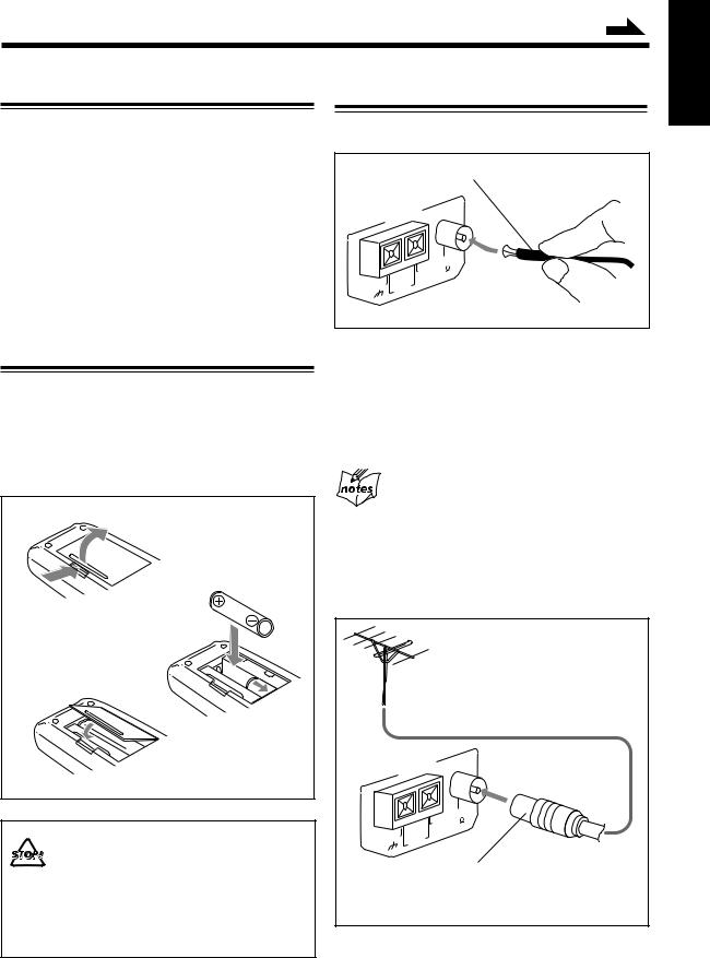
Connecting Antennas
FM antenna
FM antenna (supplied)
|
ANTENNA |
|
|
|
|
EXT |
FM |
|
AM |
75 |
|
|
|
||
GND |
AM |
COAXIAL |
|
|
|
||
LOOP |
|
|
|
|
|
|
|
1 Attach the FM antenna to the FM 75 Ω COAXIAL terminal.
2 Extend the FM antenna.
3 Fasten it up in the position which gives you the best reception.
About the supplied FM antenna
The FM antenna supplied with this unit can be used as temporary measure. If reception is poor, you can connect an outside FM antenna.
To connect an outside FM antenna
Before connecting it, disconnect the supplied FM antenna.
|
|
Outside FM antenna |
|
|
|
(not supplied) |
|
|
ANTENNA |
|
|
|
|
EXT |
FM |
|
AM |
75 |
|
|
|
||
GND |
AM |
COAXIAL |
|
|
|
||
LOOP |
|
|
|
|
|
|
|
|
|
|
A 75Ω antenna with coaxial |
|
|
|
type connector (DIN 45325) |
|
|
|
should be used. |
English
– 6 –
English
Continued
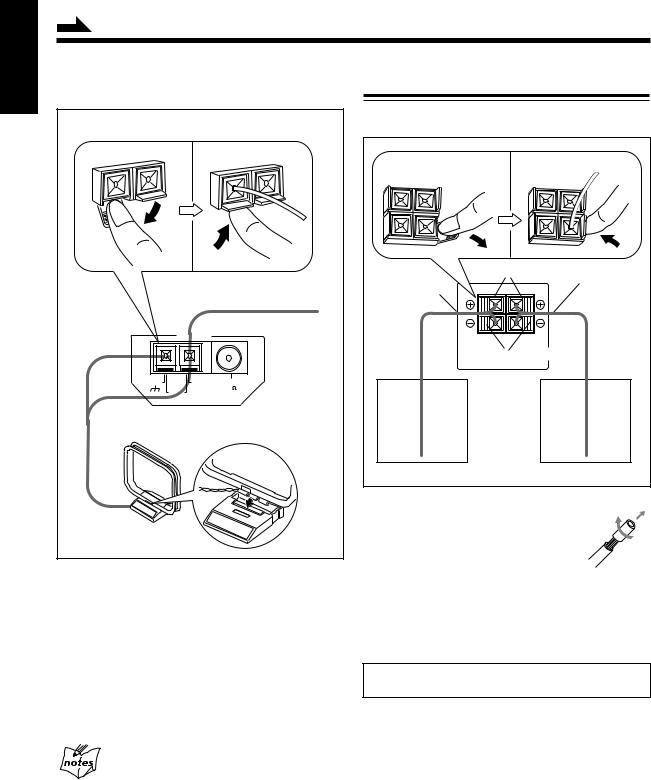
AM antenna Connecting Speakers
|
Vinyl-covered wire |
|
|
(not supplied) |
|
|
ANTENNA |
|
GND |
AM EXT |
FM |
|
AM |
75 |
|
COAXIAL |
|
|
LOOP |
|
AM loop antenna (supplied) |
||
1 Connect the AM loop antenna to the AM LOOP terminals as illustrated.
2 Turn the AM loop antenna until you have the best reception.
To connect an outside AM antenna
When reception is poor, connect a single vinyl-covered wire to the AM EXT terminal and extend it horizontally. (The AM loop antenna must remain connected.)
You can connect the speakers using the speaker cords.
2 |
|
3, 4 |
Red |
Speaker cord |
|
|
|
|
Speaker cord |
|
|
RIGHT |
LEFT |
|
Black |
SPEAKERS |
|
Right speaker |
|
Left speaker |
1 Twist the core of the cord at the end of each cord, then remove the insulation.
2 Open the speaker terminal.
3 Insert the end of the speaker cord to the terminal.
Match the polarity of the speaker terminals: Red (+) to red (+) and black (–) to black (–).
4 Close the speaker terminal on the rear of the unit.
Use only speakers with the same speaker impedance as indicated by the speaker terminals on the rear of the unit.
For better reception of both FM and AM
•Make sure the antenna conductors do not touch any other terminals and connecting cords.
•Keep the antennas away from metallic parts of the unit, connecting cords, and the AC power cord.
– 7 –
Continued
Connecting Other Equipment
You can connect the following equipment to this unit:
•Cassette deck — used as a playback and recording device.
•Audio equipment — used only as an analog playback device.
•Audio equipment with an optical digital output terminal
—used only as a digital playback device.
When you connect and use these equipment, refer also to the manuals supplied with them.
Be sure that the plugs of the audio cords and the jacks on the rear of the unit are color coded: White plugs and jacks are for left audio signals, and red ones for right audio signals.
• DO NOT connect other equipment while the power is on.
• DO NOT plug in any equipment until all connections are complete.
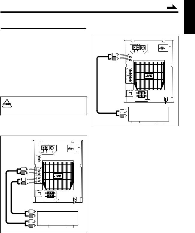
To connect audio equipment without a digital output terminal
|
|
|
220V |
|
|
|
LINE VOLTS |
|
|
230 – |
110V |
GND |
AM EXT |
240V |
127V |
FM |
|
||
|
AM |
75 |
|
|
LOOP |
COAXIAL |
|
LEFT |
|
|
|
RIGHT |
|
|
|
IN (PLAY) |
|
|
|
LEFT |
|
|
|
RIGHT |
|
|
|
LEFT |
|
|
|
RIGHT |
|
|
|
OUT (REC) |
|
|
|
DIGITAL IN |
|
|
|
OPTICAL |
|
|
|
|
RIGHT |
LEFT |
|
To output |
|
|
|
Audio equipment |
|
||
without a digital output |
|||
To connect a cassette deck
|
|
|
220V |
|
|
|
LINE VOLTS |
|
|
230 – |
110V |
GND |
AM EXT |
240V |
127V |
FM |
|
||
|
AM |
75 |
|
|
LOOP |
COAXIAL |
|
LEFT |
|
|
|
RIGHT |
|
|
|
IN (PLAY) |
|
|
|
LEFT |
|
|
|
RIGHT |
|
|
|
LEFT |
|
|
|
RIGHT |
|
|
|
OUT (REC) |
|
|
|
DIGITAL IN |
|
|
|
OPTICAL |
|
|
|
|
RIGHT |
LEFT |
|
To input |
|
|
|
|
Cassette deck |
|
|
To output |
|
|
|
Connect the audio output jacks on the other equipment and the AUX jacks, using an audio cord (not supplied).
By using audio cords (not supplied), connect:
•Between the audio input jacks on the cassette deck and the TAPE OUT (REC) jacks.
•Between the audio output jacks on the cassette deck and the TAPE IN (PLAY) jacks.
–8 –
English
English
Continued
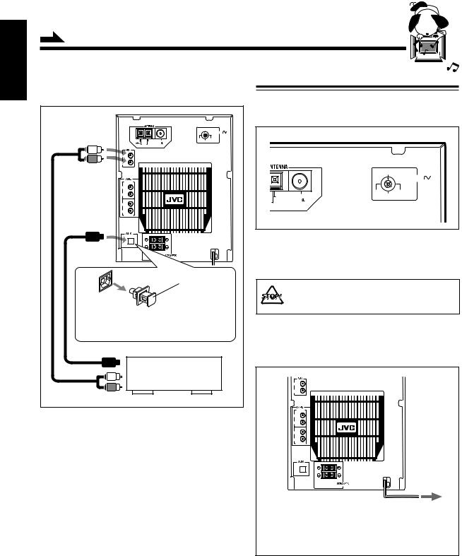
To connect audio equipment with an optical digital output terminal
|
|
|
|
220V |
|
|
|
|
LINE VOLTS |
|
|
|
230 – |
110V |
GND |
AM EXT |
FM |
240V |
127V |
AM |
|
75 |
|
|
LOOP |
|
COAXIAL |
|
|
LEFT
RIGHT
IN (PLAY) |
|
LEFT |
|
RIGHT |
|
LEFT |
|
RIGHT |
|
OUT (REC) |
|
DIGITAL IN |
|
OPTICAL |
|
RIGHT |
LEFT |
Protective plug
Before connecting the other equipment, remove the protective plug from the terminal.
To optical digital output
Audio equipment with an optical digital output
To audio output
By using both an optical digital cord (not supplied) and an audio cord (not supplied), connect:
•Between the optical digital output terminal on the other equipment and the AUX DIGITAL IN OPTICAL terminal.
•Between the audio output jacks on the other equipment and the AUX jacks.
Adjusting the Voltage Selector
Before plugging in the unit, set the correct voltage for your area with the voltage selector on the rear of the unit.
|
|
220V |
|
|
|
LINE VOLTS |
|
|
230 – |
110V |
|
AM EXT |
240V |
127V |
|
FM |
|
||
|
75 |
|
|
P |
COAXIAL |
|
|
Voltage selector |
|||
|
|||
Use a screwdriver to rotate the voltage selector so the voltage number the arrow is pointing at is the same as the voltage where you are plugging in the unit.
DO NOT plug in before setting the voltage selector switch on the rear of the unit and all connection procedures are complete.
NOW, you can plug in the unit and other connected equipment FINALLY!
LEFT |
|
RIGHT |
|
IN (PLAY) |
|
LEFT |
|
RIGHT |
|
LEFT |
|
RIGHT |
|
OUT (REC) |
|
DIGITAL IN |
|
OPTICAL |
|
RIGHT |
LEFT |
To a wall outlet
If the wall outlet does not match the AC plug, use the supplied AC plug adaptor.
When connecting the AC power cord into a wall outlet, the unit automatically starts display demonstration.
To stop the display demonstration, press any button on the unit or the remote control.
– 9 –

Basic Settings
English
Amplifier/Tuner
DISPLAY PATTERN
MULTI JOG
CONTRAST |
CLOCK/TIMER |
CANCEL |
SET |
(DISPLAY/CHARA.) |
|
|
|
Before operating the unit any further, first set the clock built in this unit, then some other basic settings.
Setting the Clock
Changing the Display Pattern
To change the display pattern of the audio level indicator
You can set the clock whether the unit is turned on or in standby mode.
1 Press CLOCK/TIMER.
The audio level indicator appears in the main display only while playing a source.
Press 1, 2 or 3.
• 1: For the following pattern:
The hour digit in the main display starts flashing.
2 Rotate MULTI JOG to adjust the hour, then press SET.
• If you want to correct the hour after pressing SET, press CANCEL. The hour digit starts flashing again.
3 Rotate MULTI JOG to adjust the minute, then press SET.
After completing the clock setting...
The analog clock in the display window shows the current time. This analog clock advances its long hand twice every 5 minutes. (When 3 minutes pass, it advances once. Then 2 minutes pass, it advances again.)
If there is a power failure
The clock loses the setting and is reset to “0:00.” You need to set the clock again.
•2: For the following pattern:
•3: For erasing the audio level indicator:
The audio level indicator is not shown, and other indications — the disc number or track number, playing time — become enlarged in the main display.
To restore the previous audio level indicator, press 3 again. (The other indications in the main display are diminished.)
To dim the display window
Press DIMMER.
Each time you press the button, the display window and the MULTI JOG dial dim and brighten alternately.
To start the display demonstration
Press DEMO.
• If the unit is in standby mode, the power turns on automatically.
To stop the demonstration, press any button. “DEMO OFF” appears.
To adjust the contrast of the display window
1Press and hold CONTRAST (DISPLAY/CHARA.) for more than 2 seconds.
The contrast adjustment display appears.
2Rotate MULTI JOG to adjust the contrast.
After completing contrast adjustment...
Pressing any button restores the previous display.
– 10 –
Common Operations
English
Amplifier/Tuner |
|
|
Remote control |
MD |
PLAY |
|
|
|
SOUND |
MULTI JOG |
|
TITLE |
|
|
|
|
|
INPUT |
MODE |
|
|
||
|
|
|
|
|
|
||
STANDBY/ON |
|
|
|
MARK |
ABC |
DEF |
SLEEP |
|
|
|
|
1 |
2 |
3 |
|
|
|
|
|
|
|
|
DISPLAY |
|
|
|
|
GHI |
JKL |
MNO |
/CHARA |
|
|
|
|
4 |
5 |
6 |
|
|
|
|
|
PQRS |
TUV |
WXYZ |
CANCEL |
|
|
|
|
7 |
8 |
9 |
|
|
|
|
|
|
|
+10 |
SET |
|
|
|
|
10 |
0 |
|
|
|
|
|
SOUND |
FM MODE |
SOUND |
BASS |
ENTER |
|
|
|
|
|
|
BASS |
|
|
|
|
|
FM/AM |
TAPE |
AUX |
CD3 |
|
|
|
|
MD |
MD |
|
CD2 |
|
|
|
|
REC PAUSE |
|
||
|
|
|
FADE |
FADE MUTING |
CD |
|
CD1 |
|
|
|
MUTING |
|
|||
|
|
|
|
|
REPEAT |
|
|
|
|
|
|
|
|
|
|
CURSOR ø / Ø |
|
VOLUME |
VOLUME |
|
|
|
|
VOLUME |
+ / – |
|
|
|
|
||
ACTIVE BASS EX. |
SET |
|
|
|
|
||
|
|
|
|
|
|||
Here are basic and common things that apply to all the functions of the unit.
Turning On the Power and Selecting the
Sources
When you press the play button for a particular source, the unit automatically turns on (and starts playing the source).
To select the external equipment as the source, press TAPE or AUX so that the unit automatically turns on.
To turn on the unit without playing, press  so that the STANDBY/ON lamp lights orange.
To turn off the unit (on standby), press  again so that the STANDBY/ON lamp lights red.
A little power is always consumed even while the unit is in standby mode.
To switch off the power supply completely, unplug the AC power cord from the AC outlet.
The STANDBY/ON lamp goes off.
When you unplug the AC power cord or if a power
failure occurs
The clock is reset to 0:00 right away, while the tuner preset stations will be erased in a few days.
Adjusting the Volume
You can adjust the volume level only while the unit is turned on.
Turn VOLUME clockwise to increase the volume or counterclockwise to decrease it.
When using the remote control, press VOLUME + to increase the volume or press VOLUME – to decrease it.
For private listening
Connect a pair of headphones to the PHONES jack. No sound comes out of the speakers. Be sure to turn down the volume before connecting or putting headphones.
PHONES jack
DO NOT turn off (on standby) the unit with the volume set to an extremely high level; otherwise, the sudden blast of sound can damage your hearing, speakers and/or headphones when you turn on the unit or start playing any source.
REMEMBER you cannot adjust the volume level while the unit is in standby mode.
To turn down the volume level temporarily
Press FADE MUTING on the remote control. To restore the sound, press the button again.
– 11 –
 Loading...