


 Loading...
COMPACT COMPONENT SYSTEM
CA-MXJD5


 EXTENDED SUPER BASS
INSTRUCTIONS
GVT0127-005A [A]

Warnings, Cautions and Others
Caution–– (STANDBY/ON) button!
Disconnect the mains plug to shut the power off completely.
The  (STANDBY/ON) button in any position does not disconnect the mains line. The power can be remote controlled.
CAUTION
To reduce the risk of electrical shocks, fire, etc.:
1.Do not remove screws, covers or cabinet.
2.Do not expose this appliance to rain or moisture.
CAUTION
•Do not block the ventilation openings or holes.
(If the ventilation openings or holes are blocked by a newspaper or cloth, etc., the heat may not be able to get out.)
•Do not place any naked flame sources, such as lighted candles, on the apparatus.
•When discarding batteries, environmental problems must be considered and local rules or laws governing the disposal of these batteries must be followed strictly.
•Do not expose this apparatus to rain, moisture, dripping or splashing and that no objects filled with liquids, such as vases, shall be placed on the apparatus.
G-1
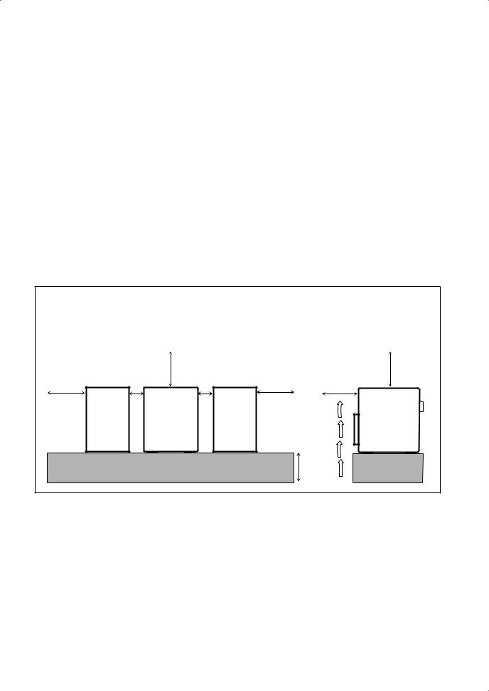
CAUTION: Proper Ventilation
To avoid risk of electric shock and fire, and to prevent damage, locate the apparatus as follows:
1.Front: No obstructions and open spacing.
2.Sides/ Top/ Back: No obstructions should be placed in the areas shown by the dimensions below.
3.Bottom: Place on a level surface. Maintain an adequate air path for ventilation by placing on a stand with a height of 10 cm or more.
|
Front view |
|
|
Side view |
|
|
15 cm |
|
15 cm |
15 cm |
1 cm |
1 cm |
15 cm |
15 cm |
|
|
CA-MXJD5 |
|
CA-MXJD5 |
|
|
|
|
10 cm |
G-2
IMPORTANT FOR LASER PRODUCTS
1.CLASS 1 LASER PRODUCT
2.CAUTION: Do not open the top cover. There are no user serviceable parts inside the unit; leave all servicing to qualified service personnel.
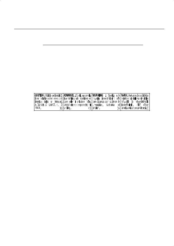
3.CAUTION: Visible and invisible laser radiation when open and interlock failed or defeated. Avoid direct exposure to beam.
4.REPRODUCTION OF LABEL: CAUTION LABEL, PLACED INSIDE THE UNIT.
G-3

Contents
Introduction ............................................................ |
2 |
Precautions .......................................................................... |
2 |
How to Read This Manual .................................................. |
2 |
Getting Started ........................................................ |
3 |
Step 1: Unpack .................................................................... |
3 |
Step 2: Prepare the Remote Control.................................... |
3 |
Step 3: Hook Up.................................................................. |
4 |
Setting the Speakers ............................................................ |
8 |
Before Operating the System ............................... |
10 |
Playable Disc Types .......................................................... |
10 |
Parts Index......................................................................... |
11 |
About the Display Indication ............................................ |
12 |
Daily Operations—Playback ............................... |
14 |
Canceling the Demonstration ............................................ |
14 |
Listening to the Radio ....................................................... |
15 |
Playing Back a Disc .......................................................... |
16 |
Playing Back a Tape.......................................................... |
18 |
Daily Operations—Sound&Other Adjustments .... |
19 |
Adjusting the Volume ....................................................... |
19 |
Reinforcing the Bass Sound .............................................. |
19 |
Adjusting the Front Speaker Output Balance.................... |
20 |
Selecting the Sound Modes ............................................... |
20 |
Creating Your Own Sound Modes—User Mode .............. |
20 |
Using Surround Mode ....................................................... |
21 |
Presetting Automatic DVD Video |
|
Sound Increase Level .................................................... |
21 |
Changing the Scanning Mode ........................................... |
21 |
Changing the Picture Tone................................................ |
22 |
Changing the Display Brightness...................................... |
22 |
Setting the Clock ............................................................... |
23 |
Turning Off the Power Automatically .............................. |
23 |
Unique DVD/VCD Operations ............................ |
24 |
Selecting the Sound Track................................................. |
24 |
Selecting the Subtitle Language........................................ |
25 |
Selecting a View Angle..................................................... |
25 |
Selecting a Still Pictures on a DVD Audio ....................... |
25 |
Playing Back a Bonus Group on a DVD Audio................ |
26 |
Special Picture Playback ................................................... |
26 |
Advanced Disc Operations ................................... |
27 |
Programming the Playing Order—Program Play.............. |
27 |
Playing at Random—Random Play................................... |
28 |
Playing Repeatedly............................................................ |
29 |
Prohibiting Disc Ejection—Child Lock ............................ |
29 |
On-Screen Disc Operations .................................. |
30 |
About the On-screen Bar................................................... |
30 |
Operations Using the On-screen Bar................................. |
31 |
Operations on the CONTROL Screen............................... |
33 |
Advanced Tape Operations ................................. |
35 |
Recording on a Tape ......................................................... |
35 |
Dubbing Tapes .................................................................. |
36 |
Synchronized Disc Recording........................................... |
36 |
Timer Operations .................................................. |
37 |
Setting the Timer............................................................... |
37 |
Timer Priority.................................................................... |
38 |
Set up Menu Operations ...................................... |
39 |
Operating Procedure.......................................................... |
39 |
7 LANGUAGE Set up Menu ............................................ |
40 |
7 PICTURE Set up Menu.................................................. |
40 |
7 AUDIO Set up Menu ..................................................... |
41 |
7 SPK. SETTING Set up Menu ........................................ |
42 |
7 OTHERS Set up Menu................................................... |
43 |
Restricting the Review—Parental Lock............................ |
44 |
Operating the TV .................................................. |
46 |
Operating TV..................................................................... |
46 |
Additional Information ........................................ |
47 |
Learning More about This System .................................... |
47 |
Maintenance ...................................................................... |
49 |
Troubleshooting ................................................................ |
50 |
Language Code List .......................................................... |
51 |
Country/Area codes list for Parental Lock........................ |
52 |
OPTICAL DIGITAL OUTPUT Signals ........................... |
53 |
Specifications .................................................................... |
54 |
1
Introduction
Precautions
Installation
•Install in a place which is level, dry and neither too hot nor too cold—between 5°C and 35°C.
•Install the System in a location with adequate ventilation to prevent internal heat buildup in the System.
DO NOT install the System in a location near heat sources, or in a place subject to direct sunlight, excessive dust or vibration.
•Leave sufficient distance between the System and the TV.
•Keep the speakers away from the TV to avoid interference with TV.
Power sources
•When unplugging the System from the wall outlet, always pull on the plug, not the AC power cord.
DO NOT handle the AC power cord with wet hands.
Moisture condensation
Moisture may condense on the lenses inside the System in the following cases:
•After starting to heat the room
•In a damp room
•If the System is brought directly from a cold to a warm place Should this occur, the System may malfunction. In this case, leave the System turned on for a few hours until the moisture evaporates, unplug the AC power cord, then plug it in again.
Internal heat
• A cooling fan is inside the unit to prevent heat buildup.
For safety, observe the following carefully:
•Make sure there is good ventilation around the unit. Poor ventilation could overheat
and damage the unit.
• DO NOT block the ventilation openings or holes. If they are blocked by a newspaper or cloth, etc., the heat may not be able to get out.
Others
•Should any metallic object or liquid fall into the System, unplug the AC power cord and consult your dealer before operating any further.
DO NOT disassemble the System since there are no user serviceable parts inside.
2
•If you are not going to operate the System for an extended period of time, unplug the AC power cord from the wall outlet.
If anything goes wrong, unplug the AC power cord and consult your dealer.
How to Read This Manual
To make the explanations in this manual as simple and easy- to-understand as possible, we have adapted the following methods:
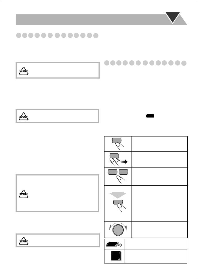
•Button and control operations are explained as listed in the table below. In this manual, the operations using the remote control is mainly explained; however, you can use the buttons and controls on the main unit if they have the same (or similar) name and marks.
•Some related tips and notes are explained later in the sections “Learning More about This System” and “Troubleshooting,” but not in the same section explaining the operations ( INFO indicates that the content has some informations). If you want to know more about the functions, or if you have a doubt about the function, go to these sections and you will find your answer there.
Indicates that you press the button briefly.
Indicates that you press the button briefly and repeatedly until an option you want is selected.
Indicates that you press one of the buttons.
Indicates that you press and hold the button for a specified period.
2 sec. • The number inside the arrow indicates the period of press (in this example, 2 seconds).
•If no number is inside the arrow, press and hold until the entire procedure is complete or until you get a result you want.
Indicates that you turn the control toward the specified direction(s).
Remote |
Indicates that this operation is only |
|
possible using the remote control. |
||
ONLY |
Indicates that this operation is only
Main Unit possible using the buttons and controls on
ONLY
the main unit.
Getting Started
Step 1:Unpack the package and check the accessories.
Step 2: Prepare the remote control.
Step 3: Hook up the components such as AM/FM antennas, speakers, etc. (see pages 4 to 7).
Finally plug the AC power cord.
Now you can operate this System.
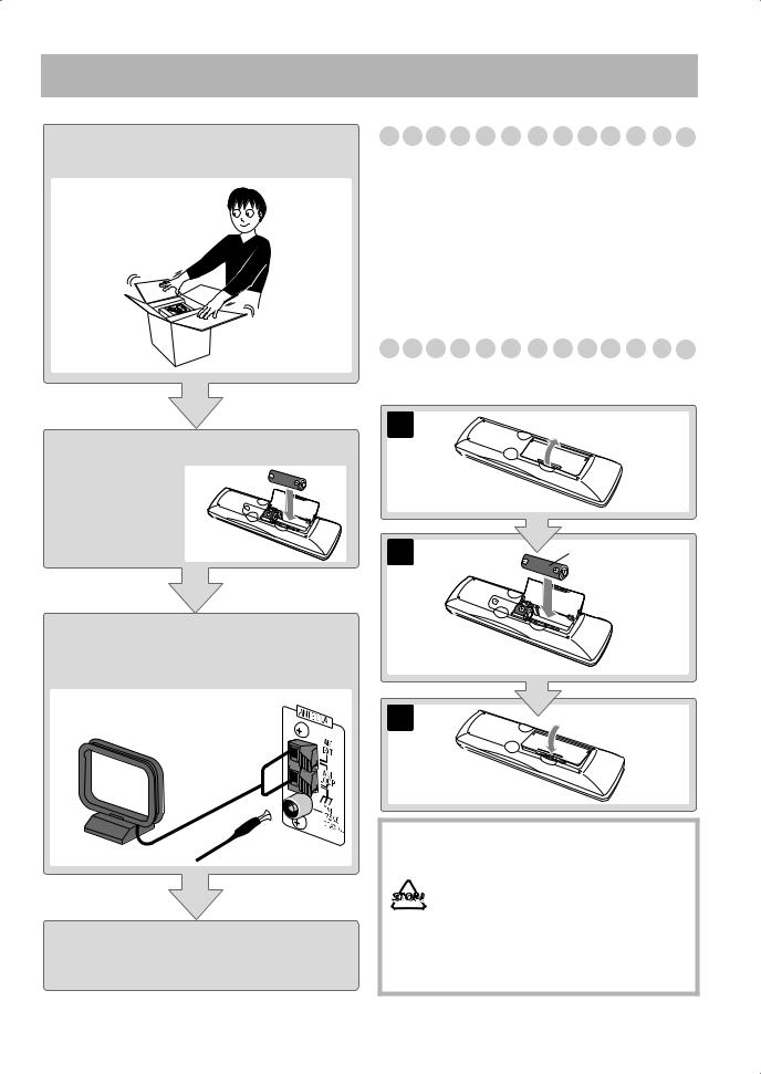
Step 1: Unpack
After unpacking, check to be sure that you have all the following items. The number in parentheses indicates the quantity of each piece supplied.
•FM antenna (1)
•AM loop antenna (1)
•Composite video cord (1)
•Remote control (1)
•Batteries (2)
•Core filter (1)
If any item is missing, consult your dealer immediately.
Step 2: Prepare the Remote Control
Insert the batteries into the remote control by matching the polarity (+ and –) correctly.
1
R6(SUM-3)/AA(15F)
3
•DO NOT use an old battery together with a new one.
•DO NOT use different types of batteries together.
• DO NOT expose batteries to heat or flame.
•DO NOT leave the batteries in the battery compartment when you are not going to use the remote control for an extended period of time. Otherwise, the remote control will be damaged from battery leakage.
3
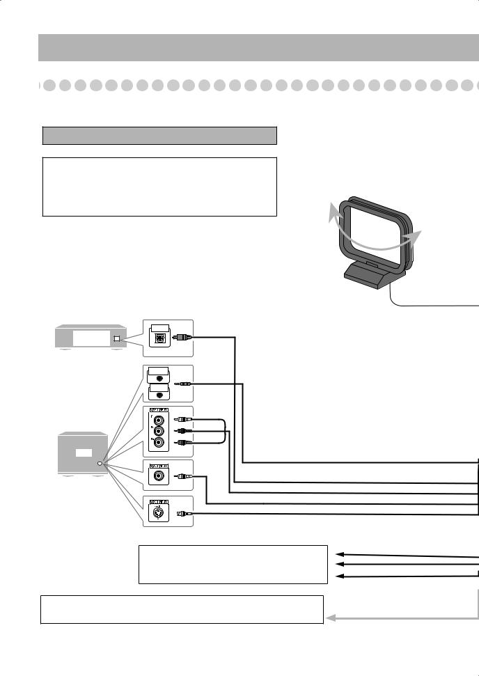
Step 3: Hook Up
If you need more detailed information, see pages 6 and 7.
Turn the power off to all components before connections.
Illustrations of the input/output terminals below are typical examples.
When you connect other components, refer also to their manuals since the terminal names actually printed on the rear may vary.
MD recorder,
Amplifier etc.
OPTICAL
DIGITAL IN
Digital Audio
Equipment
AV
COMPU LINK EX
AV
COMPU LINK II
AM loop antenna (supplied)
Turn it until the best reception is obtained.
Green
Blue
Red
TV |
Monaural mini plugs (not supplied) |
|
Yellow
Optical digital cord (not supplied)
Component video cord (not supplied)
Composite video cord (supplied)
S-video cord (not supplied)
To center speaker/Surround speaker
• See “To connect the speakers” on page 6 and “Setting the Speakers” on page 8.
To a wall outlet
Plug the AC power cord only after all connections are complete.
4
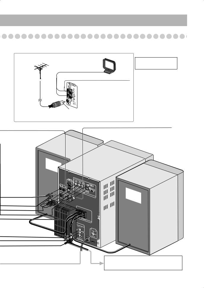
For better FM/AM reception
* This illustration uses
AM loop antenna
SP-MXJD5 as speakers.
Keep it connected.
Outdoor FM |
Vinyl-covered wire (not supplied) |
|
antenna |
||
Extend it horizontally. |
||
(not supplied) |
Disconnect the supplied FM antenna, and connect to an outdoor FM antenna using a 75 Ω wire with coaxial type connector (IEC or DIN45325).
FM antenna (supplied)
Extend it so that you can obtain the best reception.
OPTICAL
DIGITAL
OUTPUT
ªRIGHT |
|
|
· |
· |
LEFT |
|
|
ª |
To Front subwoofer
• See “To connect the speakers” on page 6 and “Setting the Speakers” on page 8.
5
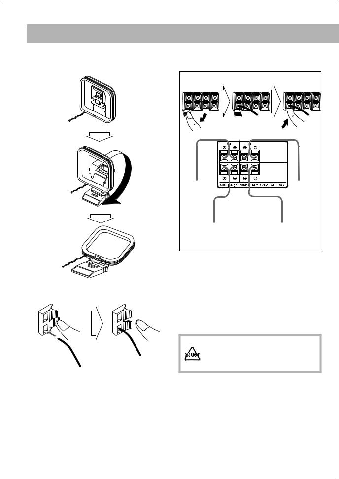
To assemble and connect the AM loop antenna
To assemble the AM loop antenna
To connect the AM loop antenna and speaker cords
1 Hold |
3 Release |
2Insert
•If the AM loop antenna wire or speaker cords are covered with vinyl, remove the vinyl to expose the tip of the antenna by twisting the vinyl.
•Make sure the antenna conductors do not touch any other terminals, connecting cords and power cord. Also, keep the antennas away from metallic parts of the System, connecting cords, and the AC power cord. This could cause poor reception.
To connect the speakers
To connect the speaker cords
1 Open |
2 Insert |
3 Close |
|
|
FRONT |
|
|
MAIN SPEAKERS |
|
|
FRONT |
|
|
SUBWOOFERS |
From right |
|
From left |
front main |
|
front main |
speaker |
|
speaker |
From |
|
From |
front subwoofer |
|
front subwoofer |
•When connecting the speaker cords, match the polarity of the speaker terminals: (+) to (+) and (–) to (–).
Speaker |
Terminal color |
|
|
|
|
|
(+) |
(–) |
|
|
|
Front main speakers |
Blue |
Black |
Front subwoofers |
Red |
Black |
|
|
|
•Use only speakers with the same speaker impedance as indicated by the speaker terminals on the rear of the unit.
•DO NOT connect more than one speaker to each terminal.
•DO NOT push or pull the speakers as this will damage the foot spacers at the bottom of the speakers.
6
To connect a center speaker and surround speakers
From center |
CENTER |
|
speaker |
||
|
From left surround speaker
From right surround speaker
•Connect the center speaker to the CENTER jack.
•Connect the left surround speaker to the LEFT jack.
•Connect the right surround speaker to the RIGHT jack.
•Use only speakers with the same speaker impedance as indicated by the speaker terminals on the rear of the unit.
To connect digital audio
OPTICAL
DIGITAL
OUTPUT
Before connecting optical digital cord, remove the protective cap from the OPTICAL DIGITAL OUTPUT terminal.
DO NOT plug in any equipment until all connections are complete.
To connect the AV COMPU LINK cords
The AV COMPU LINK control system allows you to use JVC’s TV with simple operations; by starting playing back a disc, the TV automatically turns on and changes the input mode to the appropriate position so that you can view the playback picture.
To use AV COMPU LINK, you need to connect the unit and the TV by using a cord with monaural mini-plugs (not supplied) in addition to the connection with a video cord (see page 4).
To set the video output selector
You can select the video output to match it to the color system of your TV.
NTSC: For an NTSC TV or
Multi-color system
TV.
PAL: For a PAL TV or
Multi-color system
TV.
Adjusting the Voltage Selector
Use a screwdriver to rotate the voltage selector so that the voltage marker is pointing at the same voltage as where you are plugging in the unit. (See also the back cover page.)
To connect other equipment
By using a stereo mini plug cord (not supplied), you can connect equipment with analog audio output jacks such as an MD player, a TV, etc.
Stereo mini plug cord (not supplied)
AUX
Portable audio device,
Game, etc.
(front panel)
If the audio output on the other equipment is not stereo mini plug type, use a plug adapter to convert the stereo mini plug to the corresponding plug of the audio output.
IMPORTANT
Always set volume to MIN when connecting or disconnecting the other equipment.
Voltage marker
DO NOT plug in before setting the voltage selector on the rear of the unit and all connection procedures are complete.
7
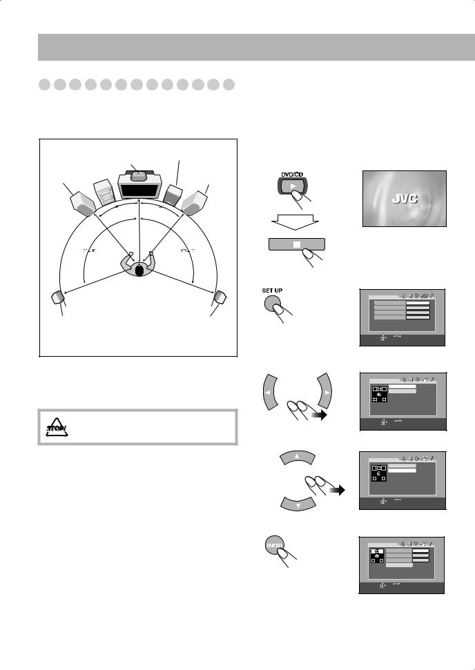
Setting the Speakers
Speaker layout
To enjoy multi-channel sound, locate speakers as follows. If you cannot locate them like this, adjust the speaker setting by using the Set up menu. (See right column.)
|
|
Front |
|
Center speaker |
subwoofer |
|
|
|
Left front |
|
Right front |
main speaker |
|
main speaker |
|
|
|
|
|
|
|
|
|
|
|
|
|
|
|
|
|
|
|
|
|
|
|
|
|
|
|
|
|
|
|
|
|
|
|
|
|
|
|
|
Left surround |
|
|
|
|
|
Right surround |
|||
|
|
|
|
|
|||||
speaker |
|
|
|
|
|
speaker |
|||
*This illustration uses SP-MXJD5 as speakers.
•You can place the front subwoofer wherever you like since bass sound is non-directional. However, it is recommended to place it in front of you.
• DO NOT place a center speaker and surround speakers on the front main speakers or the front subwoofer.
To adjust the speaker distance
You need to adjust the each speaker’s distance from where you usually take seat (listening position) to get the best surround effect.
1Turn on the TV and select the correct input mode on the TV.
2Turn on the System and change the source to “DVD/CD.”
3 Display the Set up Menu.
LAN G UAG E |
|
|
MENU LANGUAGE |
ENGLISH |
|
AUDIO LANGUAGE |
ENGLISH |
|
SUBTITLE |
|
ENGLISH |
ON SCREEN LANGUAGE |
ENGLISH |
|
SELECT |
USE |
TO SELECT. USE ENTER TO CONFIRM |
ENTER |
TO EXIT, PRESS [SET UP ]. |
|
4 Select the SPK. SETTING Set up Menus.
SPK. SETTING |
|
|
|
LEVEL |
|
|
DISTANCE |
|
SELECT |
USE |
TO SELECT. USE ENTER TO CONFIRM |
ENTER |
TO EXIT, PRESS [SET UP]. |
|
5 Select “DISTANCE.”
SPK. SETTING |
|
|
|
LEVEL |
|
|
DISTANCE |
|
SELECT |
USE |
TO SELECT. USE ENTER TO CONFIRM |
ENTER |
TO EXIT, PRESS [SET UP] . |
|
6 Enter the DISTANCE submenu.
DISTANCE |
|
|
|
|
FRONT SPEAKER |
|
3. 0m |
|
CENTER SPEAKER |
3. 0m |
|
|
SURROUND SPEAKER |
3.0dB0m |
|
|
RETURN |
|
|
SELECT |
USE |
TO SELECT. USE ENTER TO CONFIRM |
|
ENTER |
TO EXIT, PRESS [ SET UP] . |
|
|
8
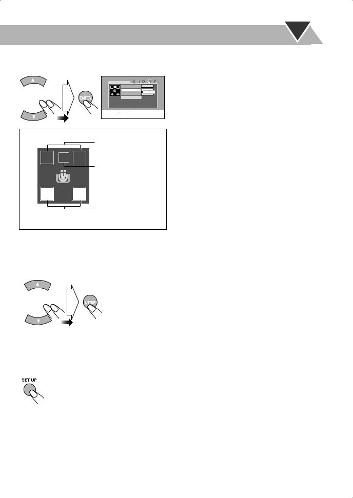
7Select the speaker to adjust the distance, then display the pop-up window.
DISTANCE |
|
FRONT SPEAKER |
3. 0m |
CENTER SPEAKER |
3. 0m |
SURROUND SPEAKER |
3. 0m |
3.0dB0m |
|
RETURN |
|
SELECT |
USE |
TO SELECT . USE ENTER TO CONFIRM |
ENTER |
TO EXIT, PRESS [SET UP]. |
|
|
|
|
Speaker Diagram
Front Speakers

 Center Speaker
Surround Speakers
• The selected speaker icon is highlighted blue.
8Adjust the desired speaker distance.
•For each speaker (FRONT SPEAKER, CENTER SPEAKER, SURROUND SPEAKER), set the distance from the listening point within the range of 0.3 m to 9.0 m in 0.3 m intervals.
9Repeat steps 7 to 8 to adjust other speakers’ distance if necessary.
To finish the setting
9
Before Operating the System
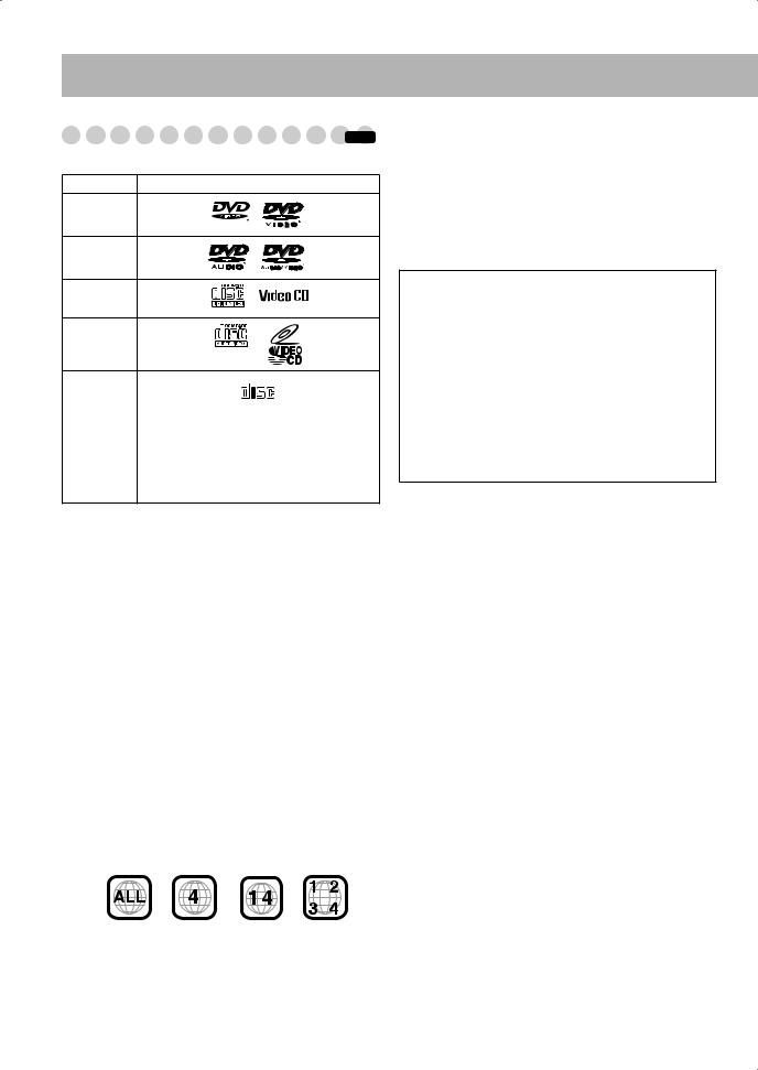
Playable Disc Types |
|
INFO |
This unit has been designed to play back the following discs:
Disc Type |
Mark (Logo) |
DVD Video
DVD Audio
Video CD
(VCD)
Super Video
CD (SVCD)
Audio CD |
|
COMPACT |
|
|
|
DIGITAL AUDIO |
|
||
|
|
|
||
|
|
|
|
|
CD-R |
The System can play back CD-R or CD-RW |
|||
|
recorded in the Audio CD, Video CD, SVCD, |
|||
CD-RW |
||||
MP3, WMA, JPEG, MPEG-4 formats. |
||||
|
||||
|
|
|
|
|
DVD-R |
The System can play back DVD-R or DVD- |
|||
DVD-RW |
RW recorded in the DVD Video format. |
|||
In addition to the above discs, this system can play back audio data recorded on CD Text, CD-G (CD Graphics), and CD-Extra.
•The following discs cannot be played back: DVD-ROM, DVD-RAM, DVD+R, DVD+RW, CD-I (CD-I Ready), CD-ROM, Photo CD, etc.
Playing back these discs will generate noise and damage the speakers.
•In this manual, “file” and “track” are interchangeably used for MP3/WMA/JPEG/MPEG-4 operations.
About color system
This System accommodates both NTSC and PAL system and can playback discs recorded with either system.
To change the color system, see page 7.
Note on Region Code
DVD players and DVDs have their own Region Code numbers. This System can play back only DVDs recorded with the NTSC or PAL color system whose Region Code numbers including “4.”
EX.:
If a DVD with the improper Region Code numbers is loaded, “REGION ERR” appears on the display and playback will not start.
Audio formats
The System can play back the following digital audio formats.
•LPCM (Linear PCM)
• DIGITAL (Dolby Digital)
•DTS (Digital Theater Systems)
•MPEG (MPEG Multichannel)
•MLP (Meridian Lossless Packing)
IMPORTANT: Before playing a disc, make sure of the following...
•Turn on the TV and select an appropriate input mode on the TV to view the pictures or on-screen displays on the TV screen.
•For disc playback, you can change the initial setting to your preference. See “Set up Menu Operations” on page 39.
If “ ” appears on the TV screen when you press a button, the disc cannot accept the operation you have tried to do, or data required for that operation is not recorded on the disc.
•Manufactured under license from Dolby Laboratories. “Dolby”, “Pro Logic”, “MLP Lossless”, and the double-D symbol are trademarks of Dolby Laboratories.
•“DTS” and “DTS Digital Surround” are trademarks of Digital Theater Systems, Inc.
•USE OF THIS PRODUCT IN ANY MANNER THAT COMPLIES WITH THE MPEG-4 VISUAL STANDARD IS PROHIBITED, EXCEPT FOR USE BY A CONSUMER ENGAGING IN PERSONAL AND NONCOMMERCIAL ACTIVITIES.
•This product incorporates copyright protection technology that is protected by method claims of certain U.S. patents and other intellectual property rights owned by Macrovision Corporation and other rights owners. Use of this copyright protection technology must be authorized by Macrovision Corporation, and is intended for home and other limited viewing uses only unless otherwise authorized by Macrovision Corporation.
Reverse engineering or disassembly is prohibited.
“CONSUMERS SHOULD NOTE THAT NOT ALL HIGH DEFINITION TELEVISION SETS ARE FULLY COMPATIBLE WITH THIS PRODUCT AND MAY CAUSE ARTIFACTS TO BE DISPLAYED IN THE PICTURE. IN CASE OF 525 OR 625 PROGRESSIVE SCAN PICTURE PROBLEMS, IT IS RECOMMENDED THAT THE USER SWITCH THE CONNECTION TO THE ‘STANDARD DEFINITION’ OUTPUT. IF THERE ARE QUESTIONS REGARDING OUR TV SET COMPATIBILITY WITH THIS MODEL 525p AND 625p DVD PLAYER, PLEASE CONTACT OUR CUSTOMER SERVICE CENTER.”
10

Parts Index


Refer to the pages to see how to use the buttons and controls.
Remote control
15, 17, 20, 21, 25 – 28, 32, 33, 44 – 46
21 26, 34 24
17
25
8, 9, 39, 40, 44
14, 15 14, 18, 35, 36 14 16, 17, 28
19
15 – 17, 20, 21, 25, 28, 46
21
14
46
23
22 27, 28 25 29, 34
17
22 


 8, 9, 17, 22, 25, 26, 28, 31 – 34, 39, 44 – 46
SET UP
31– 33
- |
- |
8, 14, 16, 26 – 28, 34 |
|
|
8, 16 – 18, 28, 34 – 36 16, 26, 28 15, 16, 18, 26
20
21
19
19 14, 19, 46
TV VOLUME
Main unit
14, 38
Remote Sensor
12
19
21
20 16, 18, 20, 26
19
16 – 18, 28, 29, 34 – 36
14
36
18, 35
|
C O M P A C T C O M P O N E N T S Y S T E M M X - J D 5 |
VOLUME |
|||||
STANDBY |
|
|
|
|
|
|
|
|
|
|
|
|
|
|
|
|
|
|
|
|
|
|
OPEN/CLOSE |
RHYTHM AX |
CD-R/RW |
|
|
|
|
|
|
|
PLAYBACK |
|
|
|
|
|
|
SURROUND |
|
|
|
|
|
|
DVD LEVEL |
MODE |
|
|
|
|
|
|
|
SOUND |
AUX |
FM/AM |
DVD/CD |
TAPE-A |
TAPE-B |
REVERSE |
|
MODE |
|
|
|
|
|
|
MODE |
|
TUNING |
|
|
PRESET |
|
||
SUBWOOFER |
|
|
|
|
|
|
|
LEVEL |
|
|
|
|
|
|
|
|
REC |
DISC REC |
|
CLOCK |
SET |
CANCEL |
|
PHONES |
START/STOP |
START DUBBING |
/TIMER /DISPLAY |
/DEMO |
AUX |
||
EXTENDED SUPER BASS
0 PUSH OPEN
A PLAY
FULL-LOGIC CONTROL
PUSH OPEN 0
REC/PLAY B
DISC SYNCHRO RECORDING
14, 19
16, 29 14 – 16, 18, 26 – 28, 34 – 36 21
 18, 35 15 – 17, 20, 23, 28, 37
16, 26, 28 14, 38
 7 15, 20, 23, 37, 38
23, 37, 38 18, 35
11
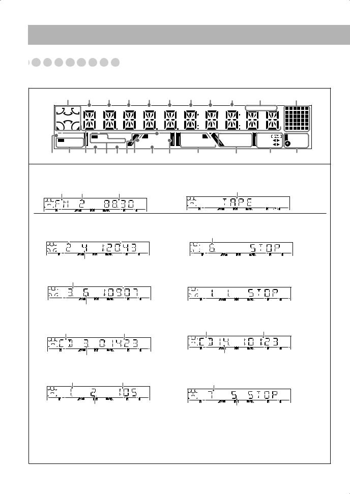
About the Display Indication


The indications on the display teach you a lot of things while you are operating the System.
Before operating the System, be familiar with when and how the indicator illuminates on the display.
|
1 2 3 4 5 6 7 8 9 p |
|
q |
||||||
L |
C |
R |
TITLE GROUP CHAP. |
TRACK MP3 |
WMA JPEG |
LPCM MONO |
ST |
|
|
|
|
|
|
|
|
|
|
|
|
|
LFE |
|
|
|
|
|
|
|
|
LS |
S |
RS |
|
|
|
|
|
|
|
|
|
|
|
|
|
|
|
||
|
|
|
|
|
|
|
|
|
|
DVD AUDIO |
PL II |
RESUME |
|
PRGM. RND. |
TAPE |
SLEEP |
|||
|
DIGITAL |
MOVIE MUSIC |
BONUS B.S.P. |
DVD LEVEL 1 2 3 |
REPEATALL |
REC A |
DAILY |
||
DTS MPEG |
SURR. SOUND |
PROGRESSIVE |
1 DISC |
|
B |
REC |
|||
w e r t y u io ; a s |
d |
|
f g |
||||||
Indications on the main display
• While listening to radio:
• While selecting “TAPE” or “AUX IN”:
Band Preset number Frequency |
Source name |
ST |
GROUP |
CHAP. |
TRACK |
MP3 |
WMA |
JPEG |
LPCM |
MONO |
ST |
|
|
|
|
|
|
|
TAPE |
|
• While playing a disc: |
|
• While disc play is stopped: |
DVD Video: |
|
DVD Video: |
Title number |
Elapsed playing time |
Total title number |
L |
C |
|
LFE
LS
DVD
R RS
TITLE |
|
CHAP. |
|
TITLE |
|
|
DVD |
Chapter number |
|
DVD Audio: |
DVD Audio: |
Group number |
Elapsed playing time |
L |
R |
GROUP |
|
C |
|
|
LFE |
|
LS |
RS |
|
DVD AUDIO 

TRACK |
|
GROUP |
TRACK |
|
DVD AUDIO |
Track number
SVCD/VCD/CD:
Disc type*1 |
Elapsed playing time*2 |
L |
R |
TRACK |
Track number
SVCD/VCD/CD: |
Total playing time*2 |
Disc type*1 |
TRACK |
Total track number
MP3*3/WMA*3/JPEG/MPEG-4*5:
Group number |
Elapsed playing time*4 |
L |
R |
GROUP |
TRACK |
MP3 |
Track number
MP3/WMA/JPEG/MPEG-4:
Current group number
GROUP |
TRACK |
Current track number
*1 Disc type is displayed with the following abbreviation: “SV (SVCD)”, “VD (VCD)”, “CD (CD)”. *2 While activating PBC function, “PBC” appears on the display instead of the playing time.
*3 When you start playing an MP3/WMA track, the track name (and Tag information) will be shown before the elapsed playing time appears.
*4 While playing back a JPEG disc, “JPEG” appears on the display instead of the elapsed playing time.
*5 When you start playing an MPEG-4 file, the file name will be shown before the elapsed playing time appears.
12

1Surround Mode/Source signal indicators
•Surround Mode indicators: light to indicate the current activated speaker.
•L/C/R/LFE/LS/S/RS: light to indicate the current source signal.
2TITLE indicator
•Lights to indicate the title number when the source is DVD Video.
•Lights to indicate the group title or track title when MP3/ WMA/JPEG/MPEG-4 title is shown on the main display.
3GROUP indicator
•Lights to indicate the group number when the source is DVD Audio or MP3/WMA/JPEG/MPEG-4 disc.
4CHAP. indicator
•Lights to indicate the chapter number when the source is DVD Video.
5TRACK indicator
•Lights to indicate the track number when the source is a disc (except for DVD Video).
6MP3 indicator
•Lights while playing back an MP3 track. 7 WMA indicator
•Lights while playing back a WMA track. 8 JPEG indicator
•Lights while playing back a JPEG file. 9 LPCM indicator
•Lights when a source signal is linear PCM. p FM reception indicators
•MONO: lights while receiving an FM stereo station in monaural.
•ST (stereo): lights while an FM stereo station with sufficient signal strength is tuned in.
q Animation indicator
wDVD AUDIO indicator
•DVD: lights when DVD Video is detected.
•DVD AUDIO: lights when DVD Audio is detected. e Source signal indicators
• DIGITAL: lights when a source signal is Dolby Digital.
•DTS: lights when a source signal is DTS Surround.
•MPEG: lights when a source signal is MPEG multichannel.
r Main display
tSURR. indicator
•Lights when Surround mode is activated. y Dolby Pro Logic II indicators
• PL II: lights when Dolby Pro Logic II mode is activated.
•MOVIE: lights when Dolby Pro Logic II Movie is activated.
•MUSIC: lights when Dolby Pro Logic II Music is activated.
uSOUND indicator
• Lights when SEA mode or USER mode is activated.
i RESUME indicator
•Lights when the Resume function is activated (see page 16).
oBONUS indicator
•Lights when DVD Audio with bonus group is detected (see page 26).
;PROGRESSIVE indicator
•Lights when the progressive scanning mode is selected. a B.S.P. indicator
•Lights when browsable still picture on DVD Audio is available (see page 25).
sDVD LEVEL 1/2/3 indicators
•Lights when the DVD Video is detected. d Disc operation indicators
•PRGM.: lights when Program Play mode is activated.
•RND.: lights when Random Play is activated.
•REPEAT: lights when Repeat Play mode is activated.
•ALL: lights when All Disc Repeat is activated.
•1: lights when One Track/Chapter/Step Repeat is activated.
fTape operation indicators
•TAPE: lights when a tape is loaded in either A or B.
•
 (reverse mode):
–
 : tape play continues endlessly.
– : tape automatically reverses once.
– : tape play stops at the end of one side.
•A: lights when a tape is loaded in the deck A.
•B: lights when a tape is loaded in the deck B.
•REC: lights while recording.
•2 3 (tape direction):
–Lights to indicate the current tape running direction.
–Flashes slowly during playback and recording.
–Flashes quickly while rewinding a tape.
gTimer indicators
• : lights when Sleep Timer is working or Daily Timer or Recording Timer stands by or is working or setting.
•SLEEP: flashes when the Sleep Timer is activated.
•DAILY: lights when the Daily Timer stands by; flashes while working or setting.
•REC: lights when the Recording Timer stands by; flashes while working or setting.
13
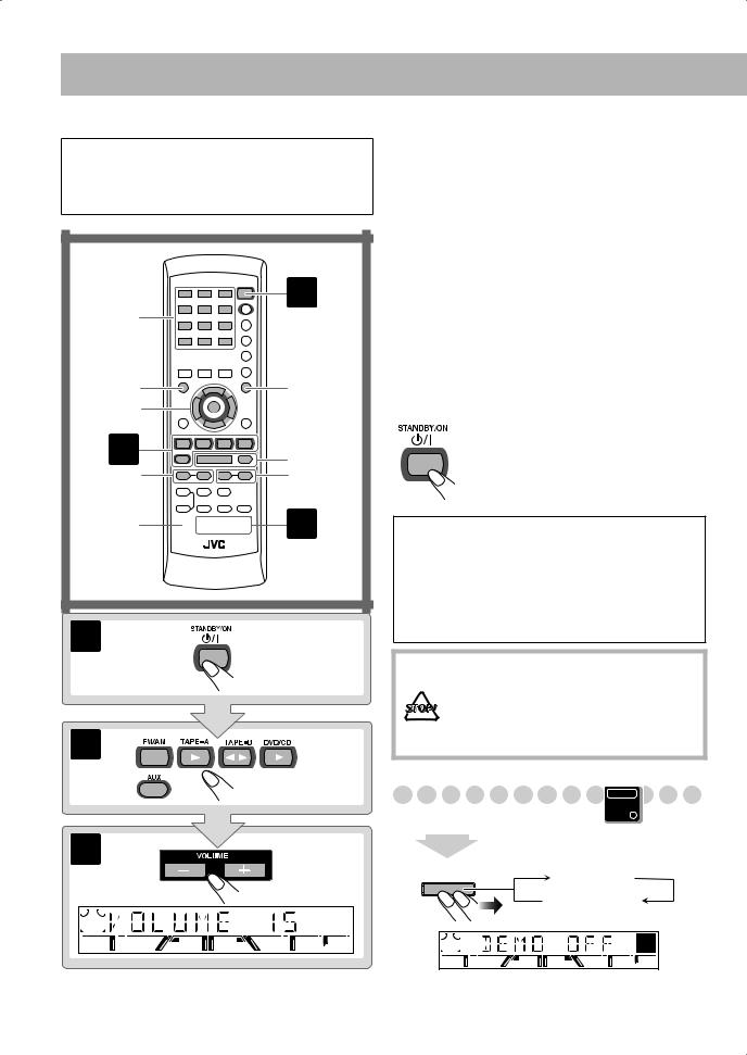
Daily Operations—Playback
In this manual, the operation using the remote control is mainly explained; however, you can use the buttons and controls on the main unit if they have the same (or similar) name and marks.
1
10 Keys
RETURN


TOP MENU |
MENU |
2/3/5/∞ |
|
ENTER |
|
2 |
7,8 |
GROUP SKIP |
1/¡ |
4/¢ |
|
SHIFT 
 3
3
1
2
3 |
¥ Turn on the power.
The STANDBY lamp on the main unit goes off.
•Without pressing  (STANDBY/ON), the System also turns on by pressing one of the source select buttons in the next step.
øSelect the source.
Playback automatically starts if the selected source is ready to start playback.
•If you press AUX, start playback source on the external component.
πAdjust the volume.
[Operate the target source as explained later.
To turn off (stand by) the system
The STANDBY lamp on the main unit lights in red.
• A small amount of power is always consumed even while on standby.
For private listening
Connect a pair of headphones to the PHONES jack on the main unit. The sound will no longer come out of the speakers. Be sure to turn down the volume before connecting or putting the headphones.
•Disconnecting the headphones will activate the speakers again.
DO NOT turn off (standby) the System with the volume set to an extremely high level; Otherwise, the sudden blast of sound can damage your hearing, speakers and/or headphones when you turn on the System or start playback.
Canceling the Demonstration
|
Main Unit |
|
ONLY |
2 sec. |
|
CANCEL |
|
/DEMO |
DEMO OFF |
|
DEMO START |
14
Loading...