


 Loading...
DDL-9000C-S
INSTRUCTION MANUAL
CONTENTS
1. SPECIFICATIONS............................................................................................................ |
1 |
|
1-1. |
Specifications of the sewing machine head...................................................................... |
1 |
1-2. |
Specifications of the control box....................................................................................... |
1 |
2. SET UP............................................................................................................................. |
2 |
|
2-1. |
Drawing of table................................................................................................................... |
2 |
2-2. |
Cautions when setting up the sewing machine................................................................ |
3 |
2-2-1. How to carry the sewing machine............................................................................................. |
3 |
|
2-2-2. Caution when placing the sewing machine............................................................................. |
3 |
|
2-3. |
Installation............................................................................................................................ |
3 |
2-4. |
Installing the thread stand.................................................................................................. |
4 |
2-5. Attaching the knee lifter pad............................................................................................... |
5 |
|
2-6. Adjusting the height of the knee lifter................................................................................ |
5 |
|
2-7. |
Installing the electrical box................................................................................................. |
6 |
2-8. |
Connecting the power switch cable................................................................................... |
6 |
2-8-1. Installing the power switch........................................................................................................ |
6 |
|
2-8-2. Connecting the power source cord.......................................................................................... |
7 |
|
2-8-3. Installing the reactor box........................................................................................................... |
8 |
|
2-9. |
Connecting the cords.......................................................................................................... |
9 |
2-10. |
Handling the cords............................................................................................................. |
10 |
2-11. Attaching the connecting rod............................................................................................ |
10 |
|
2-12. Adjustment of the pedal.................................................................................................... |
11 |
|
2-12-1. Installing the connecting rod................................................................................................ |
11 |
|
2-12-2. Adjusting the pedal angle...................................................................................................... |
11 |
|
2-13. |
Pedal operation.................................................................................................................. |
11 |
2-14. |
Lubrication.......................................................................................................................... |
12 |
2-15. |
How to use the operation panel (Basic explanation)...................................................... |
13 |
2-15-1. Selection of the language (operation to be done at first)................................................... |
13 |
|
2-15-2. Names and functions of the panel keys............................................................................... |
14 |
|
2-15-3. Basic operation....................................................................................................................... |
15 |
|
3. PREPARATION BEFORE SEWING............................................................................... |
16 |
|
3-1. Attaching the needle.......................................................................................................... |
16 |
|
3-2. |
Removing/fitting the bobbin case.................................................................................... |
16 |
3-3. |
Winding the bobbin thread................................................................................................ |
17 |
3-4. |
Threading the machine head............................................................................................ |
18 |
3-5. |
Thread tension................................................................................................................... |
18 |
3-5-1. Adjusting the needle thread tension....................................................................................... |
18 |
|
3-5-2. Adjusting the bobbin thread tension...................................................................................... |
18 |
|
3-6. |
Presser foot pressure........................................................................................................ |
19 |
3-7. Adjusting the stitch length................................................................................................ |
19 |
|
3-8. |
Changing the sewing speed.............................................................................................. |
20 |
3-9. |
LED hand light.................................................................................................................... |
21 |
3-10. |
Reverse feed stitching....................................................................................................... |
21 |
3-11. Custom switch.................................................................................................................... |
22 |
|
3-12. Adjusting the amount of oil (oil splashes) in the hook................................................... |
23 |
|
3-12-1. Adjusting the amount of oil in the hook............................................................................... |
23 |
|
i
3-12-2. How to confirm the amount of oil (oil splashes)................................................................. |
24 |
3-12-3. Sample showing the appropriate amount of oil.................................................................. |
24 |
3-13. Adjusting the thread take-up spring and the thread take-up stroke............................. |
25 |
3-14. Micro-lifting mechanism of the presser foot................................................................... |
26 |
4. HOW TO USE THE OPERATION PANEL...................................................................... |
27 |
4-1. Explanation of the sewing screen (when selecting a sewing pattern).......................... |
27 |
4-2. Sewing patterns................................................................................................................. |
30 |
4-2-1. Sewing pattern configuration.................................................................................................. |
30 |
4-2-2. Reverse feed stitching (at start) pattern................................................................................. |
31 |
4-2-3. Editing the sewing patterns..................................................................................................... |
33 |
4-2-4. List of pattern functions.......................................................................................................... |
35 |
4-2-5. Reverse feed stitching (at end) pattern.................................................................................. |
37 |
4-2-6. Teaching function..................................................................................................................... |
38 |
4-2-7. One-touch type changeover button........................................................................................ |
40 |
4-2-8. Registration of a new sewing pattern..................................................................................... |
41 |
4-2-9. Copying a pattern..................................................................................................................... |
42 |
4-3. Counter function................................................................................................................ |
43 |
4-3-1. Displaying the sewing screen under the counter display mode.......................................... |
43 |
4-3-2. Types of the counter................................................................................................................ |
43 |
4-3-3. How to set the counter............................................................................................................. |
44 |
4-3-4. How to reset the count-completion state............................................................................... |
46 |
4-4. Simplified chart of panel displays.................................................................................... |
47 |
4-5. List of memory switch data............................................................................................... |
48 |
4-6. List of errors....................................................................................................................... |
52 |
4-7. Memory switch data........................................................................................................... |
55 |
4-7-1. Setting up the memory switch data........................................................................................ |
55 |
5. MAIN NEW FUNCTIONS................................................................................................ |
57 |
5-1. Shorter-thread remaining thread trimming...................................................................... |
57 |
5-2. Adjusting the feed dog height........................................................................................... |
60 |
5-3. Operating timing of the feed............................................................................................. |
61 |
5-4. Changing the feed locus................................................................................................... |
62 |
6. CARE.............................................................................................................................. |
63 |
6-1. Maintenance mode............................................................................................................. |
63 |
6-2. Confirmation of the amount of oil in the hook oil tank................................................... |
63 |
6-3. Cleaning.............................................................................................................................. |
64 |
6-4. Applying grease................................................................................................................. |
64 |
6-5. Applying grease to the needle bar lower bushing and the presser bar bushing......... |
65 |
6-6. Replacing the fuse............................................................................................................. |
65 |
7. ADJUSTMENT OF THE MACHINE HEAD (APPLICATION)......................................... |
66 |
7-1. Needle-to-hook relationship.............................................................................................. |
66 |
7-2. Adjusting the needle thread presser device.................................................................... |
67 |
7-3. Adjusting the thread trimmer............................................................................................ |
70 |
7-3-1. For checking of the thread trimming cam timing.................................................................. |
70 |
7-3-2. Adjustment of the thread trimming cam timing..................................................................... |
70 |
7-3-3. Checking of the knife unit........................................................................................................ |
71 |
7-3-4. Adjustment of the knife unit...................................................................................... |
72 |
7-3-5. Adjustment of thread trimming speed.................................................................................... |
73 |
7-4. Adjustment of the picker................................................................................................... |
74 |
ii
7-4-1. Checking the standard adjustment......................................................................................... |
74 |
7-4-2. Standard adjustment................................................................................................................ |
74 |
7-4-3. Standard adjustment (Adjustment at the tip position).......................................................... |
74 |
7-5. Thread tension release releasing mechanism................................................................ |
75 |
7-6. Grease shortage alarm...................................................................................................... |
76 |
7-6-1. Regarding the grease shortage alarm.................................................................................... |
76 |
7-6-2. E221 Grease-shortage error.................................................................................................... |
76 |
7-6-3. Regarding K118 error resetting procedure............................................................................ |
77 |
8. HOW TO USE THE OPERATION PANEL (APPLICATION).......................................... |
78 |
8-1. Setting up the polygonal-shape stitching........................................................................ |
78 |
8-1-1. Edit method............................................................................................................................... |
78 |
8-2. Cycle pattern...................................................................................................................... |
80 |
8-2-1. Selecting the cycle pattern...................................................................................................... |
80 |
8-2-2. Creating a new cycle pattern .................................................................................................. |
81 |
8-2-3. Editing the cycle patterns........................................................................................................ |
82 |
8-3. Copying a pattern...................................................................................................................... |
84 |
8-3-1. Copying a sewing pattern........................................................................................................ |
84 |
8-3-2. Copying a cycle pattern........................................................................................................... |
85 |
8-4. Deleting a pattern............................................................................................................... |
86 |
8-4-1. Deleting a sewing pattern........................................................................................................ |
86 |
8-4-2. Deleting a cycle pattern........................................................................................................... |
86 |
8-5. Custom pitch...................................................................................................................... |
87 |
8-5-1. Selecting a custom pitch......................................................................................................... |
87 |
8-5-2. Creating a new custom pitch................................................................................................... |
88 |
8-5-3. Custom pitch edit function...................................................................................................... |
90 |
8-5-4. Copying/deleting a custom pitch............................................................................................ |
91 |
8-6. Condensation custom pattern.......................................................................................... |
93 |
8-6-1. Selecting the condensation custom....................................................................................... |
93 |
8-6-2. Creating a new condensation custom.................................................................................... |
94 |
8-6-3. Condensation custom edit function....................................................................................... |
96 |
8-6-4. Copying/deleting a condensation custom............................................................................. |
97 |
8-7. Information......................................................................................................................... |
99 |
8-7-1. Simple lock................................................................................................................................ |
99 |
8-7-2. Communication function....................................................................................................... |
100 |
8-8. How to set up the functions............................................................................................ |
102 |
8-8-1. How to change over to the function setting mode.............................................................. |
102 |
8-8-2. List of function settings......................................................................................................... |
103 |
8-8-3. Details of each selection function........................................................................................ |
104 |
8-9. External interface............................................................................................................. |
108 |
8-9-1. USB.......................................................................................................................................... |
108 |
8-9-2. NFC.......................................................................................................................................... |
109 |
iii
1. SPECIFICATIONS
1-1. Specifications of the sewing machine head
DDL-9000C-S
 -
-  B-AK154
Face plate portion lubricating method
M Semi-dry
S Micro-quantity lubrication
Seam specification
S Medium-weight materials
H Heavy-weight materials
Needle thread nipper specification
N With
0 Without
Auto-lifer
AK154 With
-Without
|
|
DDL-9000C-SMS |
|
|
DDL-9000C-SSH |
Max. sewing speed |
Stitch length 0 to 4.00 : 5,000 sti/min |
|
Stitch length 0 to 4.00 : 4,500 sti/min |
||
(standard locus) |
Stitch length 4.05 to 5.00 : 4,000 sti/min |
|
Stitch length 4.05 to 5.00 : 4,000 sti/min |
||
Stitch length |
|
5 mm |
|||
|
Hand lifter |
|
5.5 mm |
||
Presser foot lift |
Knee lifter |
|
15 mm or more |
||
|
AK154 |
|
13 mm or more |
||
Needle *1 |
1738 Nm65 to 110 (DB×1 #9 to 18) |
|
1738 Nm125 to 160 (DB×1 #20 to 23) |
||
134 Nm65 to 110 (DP×5 #9 to 18) |
|
134 Nm125 to 160 (DP×5 #20 to 23) |
|||
|
|
|
|||
Lubricating oil |
JUKI NEW DEFRIX OIL No. 1 or JUKI CORPORATION GENUINE OIL 7 |
||||
Motor |
|
AC servo motor |
|||
Horizontal feed control |
|
Electronic control |
|||
Vertical feed control |
|
Electronic control |
|||
|
|
Sewing pattern |
99 patterns (For the polygonal shape sewing, as |
||
|
|
|
many as 10 patterns can be registered.) |
||
Number of patterns |
Cycle sewing pattern |
9 patterns |
|
||
|
|
Custom-pitch pattern |
20 patterns |
|
|
|
|
Condensation custom pattern |
9 patterns |
|
|
SMS ;
- Equivalent continuous emission sound pressure level (LpA) at the workstation: A-weighted value of 81.5 dBA ; (Includes KpA = 2.5 dBA) ; according to ISO 10821-
Noise C.6.2 -ISO 11204 GR2 at 5,000 sti/min. SSH ;
-Equivalent continuous emission sound pressure level (LpA) at the workstation: A-weighted value of 77.5 dBA ; (Includes KpA = 2.5 dBA) ; according to ISO 10821- C.6.2 -ISO 11204 GR2 at 4,500 sti/min.
•The sewing speed will vary depending on the sewing conditions. The sewing speed preset at the time of shipping is 4,000 sti/min.
*1 : Needle used depends on the destination.
1-2. Specifications of the control box
Supply |
Single phase |
3-phase |
Single phase |
Single phase |
voltage |
100 to 120V |
200 to 240V |
220 to 240V |
220 to 240V CE |
|
|
|
|
|
Frequency |
50Hz/60Hz |
50Hz/60Hz |
50Hz/60Hz |
50Hz/60Hz |
Operating |
Temperature : 0 to 35˚C |
Temperature : 0 to 35˚C |
Temperature : 0 to 35˚C |
Temperature : 0 to 35˚C |
environment |
Humidity : 90% or less |
Humidity : 90% or less |
Humidity : 90% or less |
Humidity : 90% or less |
Input |
520VA |
520VA |
520VA |
350VA |
|
|
|
|
|
– 1 –

2. SET UP |
|
|
|
|
|
|
|
|
|
|
|
|
|
|
|
|
|
|
|
|
|
|
|
|
|
|
|
|
|
|
|
|||
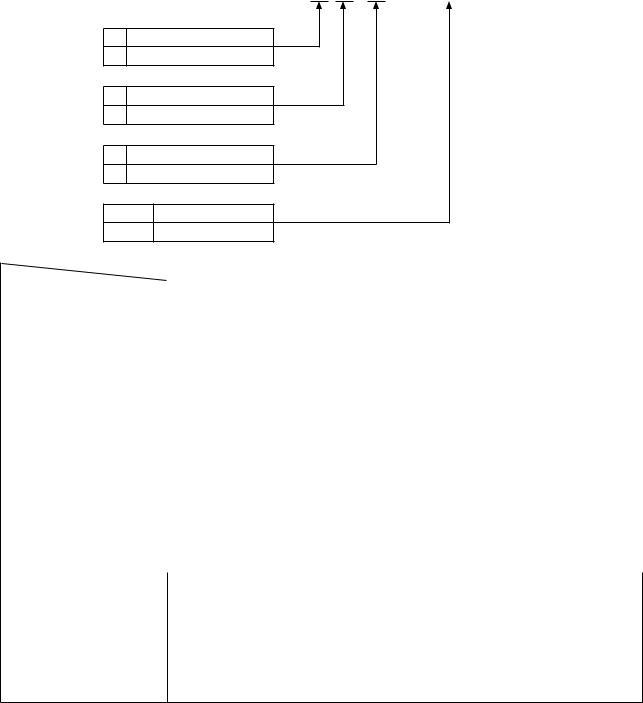
2-1. Drawing of table |
|
|
|
|
|
|
|
|
|
|
|
|
|
|
|
|
|
|
|
|
|
|
|
|
|
|
|
|
||||||
|
|
|
|
|
|
|
|
|
+0.5 0 |
|
|
|
|
|
|
|
|
0 |
|
|
|
|
10 |
|
for |
|
|
-Y |
for |
|
|
|
||
|
|
|
|
|
|
|
|
|
|
|
|
|
|
|
|
|
|
|
|
|
|
-X drawing |
5.1±0 |
drawing |
|
|
|
|||||||
|
|
|
|
|
|
|
SS- |
|
20 |
|
|
|
|
|
|
|
|
+0.521 |
|
|
|
R2 |
|
|
|
cushion |
reference |
|
|
cushion |
|
|
|
|
|
|
|
|
|
|
|
|
|
|
|
|
|
|
|
|
|
|
|
|
|
|
|
Rubber |
|
|
Rubber reference |
5.2±0.1 |
|
||||||
|
U - U |
|
|
|
|
|
|
|
|
|
|
|
|
|
|
|
|
|
|
|
|
|
|
|
|
installing X - X |
|
|
Y |
installing Y - Y 1.2±0.5 |
|
|
||
|
|
|
R2 |
|
|
|
|
|
|
|
|
|
|
40° |
40° |
|
|
|
|
|
|
R2 |
|
|
X |
|
|
|
|
|
|
|
||
|
|
|
|
|
|
|
|
|
|
|
|
|
|
|
|
|
|
|
|
|
|
R2 |
|
|
|
|
|
|
|
|
|
|
|
|
|
|
R2 |
|
|
|
|
|
|
|
|
|
|
|
|
|
|
|
|
|
|
|
|
14 |
|
|
|
|
|
|
|
|
|
|
|
|
|
|
|
|
|
|
|
|
|
|
|
535 |
|
|
|
|
|
|
|
|
|
|
|
|
|
|
|
|
|
|
|
|
|
|
|
|
|
70 |
|
|
|
|
|
|
360 |
|
|
|
|
|
|
|
|
|
|
|
|
|
|
|
|
|
|
|
|
|
|
||
|
|
|
50 |
|
|
|
|
|
|
|
|
|
|
|
322 |
|
|
|
|
|
|
|
|
|
|
|
|
|
|
|
|
|
|
|
|
|
|
|
|
|
|
|
|
|
|
|
|
|
141 |
|
|
|
|
139 |
|
|
|
|
|
|
|
|
|
|
|
|
|
|
|
|
|
|
|
|
|
|
18 |
|
|
|
|
43 |
|
5.86 |
|
|
|
55 |
5 |
17 |
|
|
|
|
|
locations) |
|
|
8.5 |
|
|
|
||
|
|
|
|
|
|
|
|
|
|
|
|
|
W |
|
|
|
|
R8 |
|
|
|
|
|
|
|
|
|
|
|
|
||||
|
|
|
|
|
|
|
|
|
|
|
|
|
|
5.21 |
|
R8 |
|
|
|
|
|
R6 |
5.27 |
|
R2R2 |
V(1:1) |
|
|
|
|
|
|
||
|
|
|
|
|
|
|
|
|
|
|
|
|
|
84 |
5.21 |
|
|
|
40 |
R30 |
|
|
|
40 |
|
|
|
|
|
|
|
|||
|
|
|
|
|
|
|
|
|
|
|
|
|
|
|
|
|
|
|
|
|
|
|
18 |
|
|
|
V |
26 |
|
|
|
|
|
|
|
|
50 |
|
|
|
|
|
|
R8 |
|
|
|
|
|
9 |
|
F |
|
|
|
|
52.5 |
|
50 |
|
|
|
|
|
|
||||
|
|
|
|
|
|
|
|
S |
|
|
|
|
|
14 |
52 |
R27 |
|
|
|
|
|
(4 |
|
|
|
|
|
|
||||||
|
|
|
R30 |
|
|
|
|
|
|
|
|
|
|
|
|
|
|
|
|
|
|
|
|
|
|
|
|
- |
|
|
|
|
|
|
|
|
|
|
|
|
|
|
|
|
|
|
|
|
|
|
|
|
|
. |
|
|
|
|
|
|
|
|
|
|
|
|
|
||
90 281 |
156.5 |
|
C |
|
138.5 |
56 110.5 |
|
|
|
|
|
E D |
|
|
|
|
|
90 |
195 |
154.6 |
115 |
|
Q-Q 26 |
16 |
|
IT-T |
|
|
||||||
|
V |
V |
|
|
|
|
|
|
|
|
|
|
|
|
|
|||||||||||||||||||
|
|
|
|
|
|
|
75 |
|
.5 |
|
|
|
|
|
|
|
|
|
|
|
|
|
S |
|
|
|
|
|
1 |
8 |
|
|
|
|
|
|
|
|
|
|
|
2×R20 |
R242 |
|
|
|
|
|
|
R242.5 |
|
|
|
|
|
|
|
|
|
|
|
|
|
|
|
|
|||
|
|
|
|
|
|
|
|
|
|
|
|
|
|
|
|
|
|
|
|
|
|
|
|
|
|
|
|
|
|
|
|
|
||
|
|
|
|
|
|
|
|
|
R8 |
G |
|
|
|
R8 |
|
|
|
|
|
|
|
|
|
|
|
|
|
|
|
|
|
|
||
|
|
|
|
|
|
|
|
|
|
|
|
|
|
|
|
|
R18 |
|
|
|
|
|
|
|
|
|
|
|
|
|
|
|
|
|
|
|
|
|
V |
|
|
V |
|
|
|
|
|
|
|
68.5±0.5 |
|
|
|
|
|
|
|
|
|
|
C1 |
|
|
|
|
|
|
|
|
|
|
|
|
|
|
|
|
|
|
|
|
|
|
|
|
|
|
|
|
|
|
|
|
|
|
|
|
|
|
|||||
|
|
|
|
|
|
|
|
|
R20 |
|
|
5.R22 |
|
|
|
5 |
5 |
|
|
|
|
|
|
|
5±1.9 |
|
|
|
|
|
||||
|
|
|
|
|
|
|
|
|
|
|
|
|
|
|
|
|
|
|
|
|
|
|
|
|
|
|
|
|
||||||
|
|
|
|
|
|
|
|
|
|
|
|
|
|
|
|
|
|
. |
|
|
|
|
|
|
|
|
|
|
|
|
||||
|
|
|
|
|
|
|
|
|
|
|
|
|
|
|
|
|
R22 |
. |
R8 |
R27 |
|
|
|
|
|
|
|
|
32±1 |
|
|
|
||
|
|
|
|
|
|
|
|
|
R01 |
|
|
|
|
|
|
|
|
|
|
|
|
|
|
|
|
|
|
|
||||||
|
|
|
|
|
|
|
|
|
|
|
|
|
|
|
|
|
|
|
|
|
H |
|
|
|
locations)(2 |
|
|
|
|
|
|
|||
|
320 |
|
|
|
|
X |
|
R10 |
|
80 X |
|
|
|
|
|
|
|
|
|
|
|
|
|
|
|
5.5±0.19 |
|
|
|
|||||
|
|
|
|
|
|
|
|
|
|
|
|
|
|
|
|
|
|
|
|
|
|
|
|
|
|
|
|
|
|
|
|
|
|
|
|
|
|
|
|
|
|
|
|
29 |
|
|
|
|
|
|
|
|
|
|
|
|
|
|
|
|
|
|
Z-Z |
|
|
|
|
|
|
|
|
|
|
|
|
|
|
|
|
|
|
|
|
|
|
|
|
|
|
|
|
|
|
|
|
|
|
|
|
|
|
|
|
|
|
|
|
|
|
|
|
|
|
|
|
|
|
|
|
279±1 |
|
|
|
|
|
|
|
|
|
520 |
|
|
locations)(2 |
|
|
5.5±0.23 |
|
|
|
|
|
|
48 |
|
|
|
|
|
T |
|
|
T |
|
|
|
|
|
|
|
|
|
|
|
|
|
|
|
|
|
|
|
|||
|
|
|
54 |
|
116 |
|
|
|
|
|
|
|
|
|
|
|
|
|
|
|
|
|
|
|
|
|
|
Y |
|
|
|
|
|
|
|
|
|
|
|
|
|
|
|
|
|
|
|
|
|
|
|
|
|
|
|
|
|
|
|
|
Y- |
|
|
|
|
|
|
||
|
|
|
|
|
|
|
|
|
|
|
|
|
|
|
|
|
|
|
|
|
|
|
|
|
|
|
|
|
|
|
|
|
|
|
|
|
|
|
|
|
|
|
|
29 |
|
|
|
|
|
|
|
|
|
|
|
|
|
|
|
|
|
|
|
|
|
|
|
|
|
810 |
|
|
|
V |
|
|
V V X |
|
|
80 X |
|
|
|
|
|
|
|
|
|
|
|
|
|
|
|
locations)( |
|
|
|
|
|
|
||
|
|
|
V |
|
|
|
|
|
|
|
|
|
|
|
|
|
|
|
|
|
|
|
|
|
5.5±0.17 |
|
|
|
||||||
|
|
|
|
|
|
|
|
|
R10 |
|
|
|
|
|
|
|
|
|
|
|
|
|
|
|
|
|
|
|
|
|
|
|
|
|
|
|
|
|
|
|
|
|
|
R10 |
|
|
|
|
|
|
|
|
|
|
|
|
|
|
|
|
|
|
X-X |
|
|
|
|
|
|
|
|
|
|
|
|
|
|
|
|
|
|
|
|
|
|
|
|
|
|
|
|
|
|
|
|
|
(2 |
|
|
|
|
|
|
|
|
|
|
|
|
|
|
|
|
|
|
|
|
|
|
|
|
|
|
|
|
|
|
|
|
|
|
|
|
|
|
|
set-up.) |
|
|
1200 |
|
|
|
|
|
|
|
|
|
|
|
5 |
|
|
172.5 |
Y |
5 |
|
|
|
|
|
|
|
W-W |
|
set-up.) |
|
|
|
|
|||
|
|
|
|
|
|
|
|
|
|
|
R22 |
. |
|
|
|
|
. |
|
|
|
|
|
|
|
|
|
|
|
|
|
|
|
|
|
|
|
|
|
|
|
|
|
|
|
|
|
|
|
|
|
R22 |
|
|
|
|
|
|
|
|
|
of |
|
|
|
of |
|
|||
|
|
|
|
|
|
|
|
|
|
|
|
|
|
Z |
|
|
|
|
|
|
|
|
|
|
|
|
|
|
|
|
|
|||
|
|
U |
|
|
|
|
|
|
|
|
|
|
|
|
80 |
|
|
R18 |
Y |
|
|
|
|
U |
C1 |
|
time |
|
|
|
time |
|
||
|
|
|
|
|
|
|
|
R20 |
|
|
|
|
|
|
|
|
|
|
|
R2 |
|
|
|
|
|
|||||||||
|
|
|
|
|
|
|
|
|
|
|
|
|
R20 |
|
|
|
|
|
|
|
|
|
|
|
27 |
theatholea side)reverse |
|
|
theatholea |
|
||||
|
|
|
|
|
|
|
|
|
|
|
|
|
|
|
|
|
|
|
|
|
|
|
|
|
|
|
|
|||||||
|
|
|
|
|
|
|
|
|
Z |
|
|
R30 |
|
|
R20 |
|
|
|
|
|
|
|
|
|
40° |
|
|
|
||||||
|
|
|
|
|
|
|
|
|
|
|
|
|
|
|
|
|
|
|
|
|
|
|
|
|
|
|
|
|
|
|
|
|
||
|
|
|
|
|
|
|
|
|
|
|
|
|
|
|
|
R03 |
|
|
|
|
|
|
|
|
|
|
|
|
|
|
|
|
|
|
|
|
|
|
|
|
|
|
.(225) |
|
|
|
136 |
|
|
|
5.22 |
|
|
|
|
|
|
|
|
|
|
|
|
|
|
|
|||
|
|
|
|
|
(244) |
|
|
|
|
|
|
|
-1 |
|
|
|
|
110 |
|
|
|
|
|
|
|
|
|
|
|
|
|
|||
|
|
|
|
|
|
|
|
|
|
|
|
0 |
181 |
|
|
|
|
|
|
|
|
|
|
|
|
|
|
|
|
|
||||
|
|
|
|
|
|
|
|
|
|
|
|
|
|
|
|
|
|
|
|
|
|
|
|
40 525.4 |
|
|
20(Drill (on the |
|
10depth2×ø3.5, |
10(Drill |
only)side(hingeC2.5toC1.5 |
|||
|
|
|
A |
|
100 |
|
|
|
|
|
|
|
|
W |
|
|
|
|
|
|
|
|
|
|
|
surface,bottomtheon4×ø3.4depth stopperdrawerofpositionInstalling holedrilledø17 holedrilledø133× 10depth2×ø3.5, |
holeThrough surface,bottomtheon2×ø3.4depth |
|||||||
|
|
|
|
|
|
|
|
|
|
|
|
|
|
|
|
|
|
|
|
|
|
|
|
|
|
|
|
|
|
|
|
|
|
|
|
|
|
|
B |
|
|
|
|
|
|
|
|
|
|
|
|
|
|
|
|
|
|
|
|
|
|
|
|
|
|
|
|
|
|
|
|
|
R30 |
|
|
|
|
|
|
|
|
|
|
|
|
|
|
|
|
|
|
R30 |
|
|
|
R2 |
|
|
|
|
|
|
|
|
|
|
|
|
|
|
|
|
|
|
|
|
|
|
|
|
|
|
|
|
|
|
R6 |
|
|
|
R2 |
|
|
|
|
|
|
|
|
|
|
|
|
|
|
|
|
|
|
|
|
|
|
|
|
|
|
|
|
|
|
|
|
|
|
6 |
A B C D E F G H I |
|||||||
|
|
|
|
|
|
|
|
|
|
|
|
|
|
|
390 |
|
|
|
|
|
|
|
|
|
|
|
|
|||||||
|
|
|
|
|
|
|
|
|
|
|
|
|
|
|
|
– 2 – |
|
|
|
|
|
|
|
|
|
|
|
|
|
|
|
|
||
2-2. Cautions when setting up the sewing machine
Thank you very much for the purchase of JUKI Industrial Sewing Machine this time. Make sure of items 2-1 through 2-14 before operating to use this sewing machine with ease.
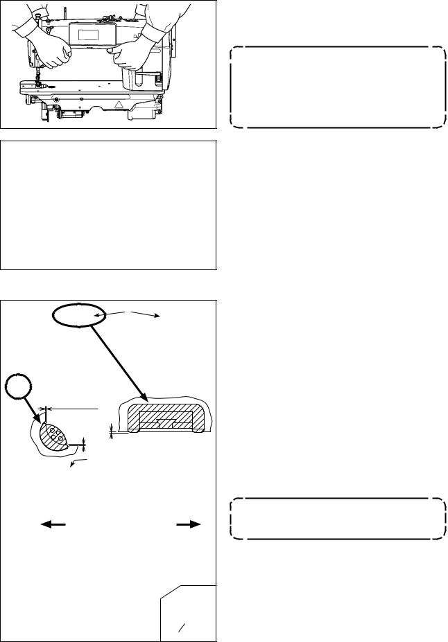
2-2-1. How to carry the sewing machine
Carry the sewing machine while holding the machine arm with two persons as shown in the figure.
1. Never hold the handwheel since it rotates.
2. Be sure to handle the sewing machine with two persons or more since the sewing machine weighs 40.5 kg or more.
2-2-2. Caution when placing the sewing machine
Place the sewing machine on a horizontal and plane place when placing it and do not place any protruding thing such as a screwdriver or the like.
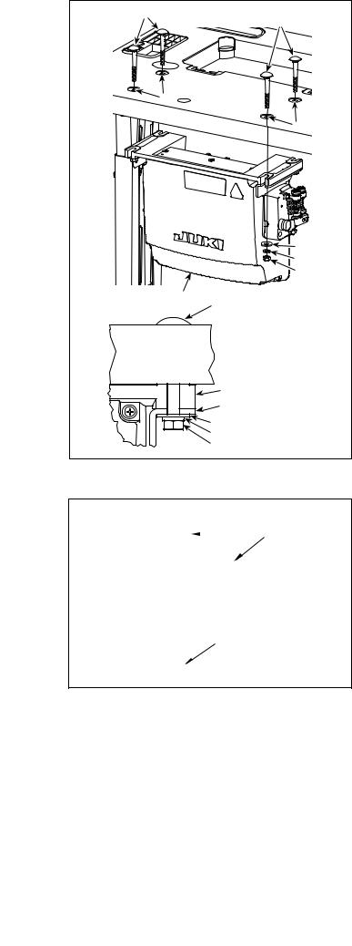
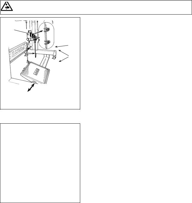
2-3. Installation |
|
|
|
|
|
|
|
|
|
|
|
|
|
|
1.2 ± 0.5 mm |
|
|
|
1 ± 0.5 mm |
|
|
1.2 ± 0.5 mm |
|
23.5 mm |
|
19.5 mm |
|
||
|
|
|
|
|
|
|
A |
B |
|
|
|
|
|
|
|
|
|
|
|
|
1)The under cover should rest on the four cor-
ners of the machine table groove. Mount rubber hinge seat on the table and fix it on the table with a nail.
2)Fix two rubber seats on side A (operator’s side) using nails as illustrated above. Fix two cushion seats on side B (hinged side) using a
rubber-based adhesive. Then place under cover
on the fixed seats.
3)Fit knee lifter pressing rod . Fit hinge into the
opening in the machine bed, and fit the machine head to table rubber hinge seat before placing the machine head on cushions on the four corners.
Do not hold the handwheel.
– 3 –
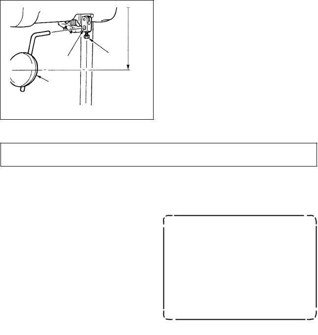
4) Securely attach head support rod to the table until it goes no further.
Be sure to mount the machine head
support rod on the machine table so
that its height from the table surface
becomes 63 to 68 mm. For the sewing
machine provided with the AK device,
be sure to mount the support rod on
the table so that its height from the table surface becomes 33 to 38 mm.
5) Bundle cable clip band supplied as accessories
of the machine head at the root of the cable.


2-4. Installing the thread stand

1)Assemble the thread stand unit, and insert it in the hole in the machine table.
2)Tighten nut .
3)For ceiling wiring, pass the power cord through spool rest rod .
– 4 –
2-5. Attaching the knee lifter pad
220 mm
Insert knee lifter pad into attaching hole and tighten it with bolt .
*Adjust the position of knee lifter pad to a convenient place.
For the reference dimension, the position is 220 mm from the bottom face of table.
2-6. Adjusting the height of the knee lifter
WARNING :
Turn OFF the power before starting the work so as to prevent accidents caused by abrupt start of the sewing machine.
|
|
|
The standard height of the presser foot lifted using |
|
|
|
the knee lifter is 10 mm. |
|
|
|
You can adjust the presser foot lift up to 15 mm |
|
|
|
using knee lifter adjust screw . |
|
|
|
1. Do not operate the sewing machine |
|
|
in the state that the presser foot |
|
|
|
is lifted by 10 mm or more since the |
|
|
needle bar comes in contact with |
||
|
|
|
the presser foot . |
|
|
|
|
|
|
|
2. Knee lifter initial position |
|
|
|
If the adjustment screw is over |
|
|
tightened, the sewing machine will |
|
|
|
operate in a state where the presser |
|
|
foot is lifted up, causing defective |
||
|
|
|
|
|
|
|
sewing or noise. |
|
|
|
|
– 5 –
2-7. Installing the electrical box
|
|
|
|
|
|
|
a |
|
|
|
a |
|
|
|
|
|
|
|
|
|
|
|
|
|
|
|
|
|
Frame |
|
|
Pedal sensor |
|
|
|
|
|
|
|
|
|
Install control box on the table using four holes a in the table. Secure the control box with four bolts, four plain washers , four spring washers and four hexagonal nuts supplied with the control box.
At this time, insert the nut and washer supplied with the unit as accessories as shown in the figure so that the control box is securely fixed.
2-8. Connecting the power switch cable
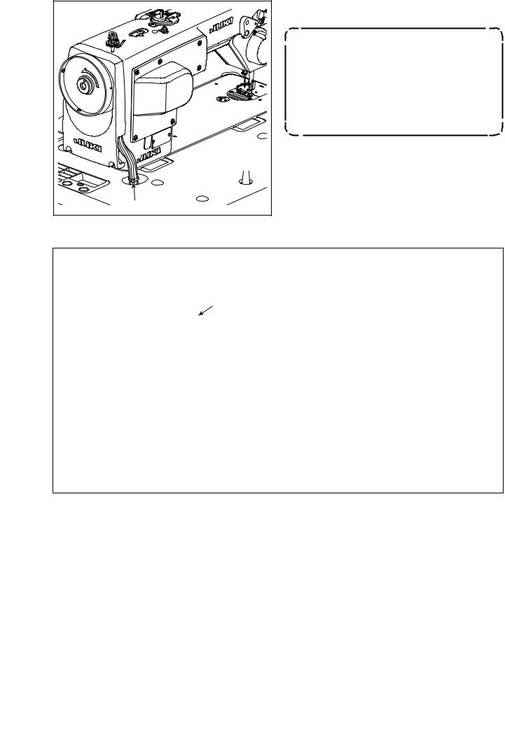
2-8-1. Installing the power switch
Fix power switch under the machine table with wood screws .
Fix the cable with staples supplied with the machine as accessories in accordance with the forms of use.
– 6 –
2-8-2. Connecting the power source cord
Voltage specifications at the time of delivery from the factory are indicated on the voltage indication seal. Connect the cord in accordance with the specifications.
Power indication tag
Never use under the wrong voltage and phase. 
(For example : In the case of 200V) |
Rating plate |
|
• Connecting single phase 220 to 240V
Brown |
Brown |
|
|
Table |
|
|
|
Control box |
Green/Yellow |
Light blue |
AC220 to 240V |
Green/Yellow |
|
Brown |
|
|
Green/Yellow — GND |
||
|
|
||
|
Power switch |
|
|
Light blue Light blue |
|
|
|
• Connecting 3-phase 200 to 240V
|
White |
White |
|
|
Table |
|
|
|
|
|
|
Green/Yellow |
White |
|
Control box |
|
Black |
AC200 to 240V |
|
Green/Yellow |
|
|
Red |
|
Black |
Black |
|
Green/Yellow — GND |
|
Red |
|
|
||
Red |
|
|
|
|
Power switch
• Connecting single phase 100 to 120V
Brown Brown
Table
Green/Yellow
Control box
Green/Yellow
|
|
|
Light blue |
|
Power switch |
Light blue |
||
– 7 –
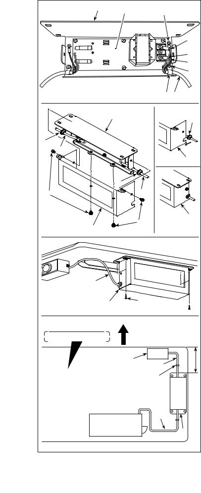
2-8-3. Installing the reactor box
* For the EU-type models, install the reactor box that is supplied with the sewing machine.
|
|
|
|
|
1) Connect the terminals of power cord of the |
|
|
SC-950(951) to reactor-box PCB asm. and |
|||
|
|
|
|||
|
|
|
|
|
to reactor box mounting plate . |
|
|
|
|
A |
Connect brown wire A to the first connector |
|
|
|
|
and blue wire B to the third connector respec- |
|
|
|
|
|
|
|
|
|
|
|
C |
tively from the top of terminal block on the |
|
|
|
|
B |
reactor box PCB asm. using screws. Connect |
|
|
|
|
|
green/yellow wire C to reactor box mounting |
|
|
|
|
|
plate with earth setscrew . |
|
|
|
|
|
2) Attach cable clip to the power cord of SC- |
|
|
|
|
|
950(951). Attach the power cord together with |
|
|
|
|
|
the cable clip to reactor box mounting plate |
|
|
|
with cable clip setscrew . |
||
|
|
|
|
||
|
|
|
|
|
3) Attach cord bushes to input/output cables |
|
|
|
|
and of the reactor box. Attach both bush- |
|
|
|
|
|
|
es in the same manner. |
|
|
|
|
|
|
|
|
|
|
4) Attach reactor box cover to reactor box |
|
|
|
|
|
|
|
|
|
|
|
|
mounting plate with four reactor-box cover |
|
|
|
|
|
setscrews . |
|
|
|
|
At this time, fix cord bushes attached to |
|
|
|
|
|
|
input/output cables and in the concave |
|
|
|
|
|
section on reactor box cover to eliminate a |
|
|
|
|
gap between reactor box and cover . |
|
|
|
|
|
||
|
|
|
|
5) Install reactor box on the table stand with |
|
|
|
|
|
|
|
|
|
|
|
|
four accessory wood screws at the position |
|
|
|
|
|
that is approximately 200 mm away from the |
|
|
|
|
|
front end of table stand. |
|
|
|
|
|
Adjust the installing position according to the |
|
|
|
|
|
size of table stand so that the reactor box does |
|
|
|
|
|
not protrude from the edge of table stand. |
|
|
|
|
|
6) Fix input/output cables and of reactor |
|
|
|
|
|
box on the table stand using accessory cord |
|
|
|
|
|
staple . |
Undersurface of table |
Operator's side |
|
At this time, take care not to cross the input- |
||
|
|
|
and output-cables. |
||
|
|
|
|
|
|
|
Power box |
|
mm |
|
|
|
|
200 |
|
||
|
|
|
|
||
|
|
|
|
|
|
|
|
|
|
|
|
|
|
|
|
|
|
SC-950(951) |
|
|
|
||
|
|
|
|
|
|
|
|
|
|
– 8 – |
|
2-9. Connecting the cords
DANGER :
1.To prevent personal injuries caused by electric shock hazards or abrupt start of the sewing machine, carry out the work after turning OFF the power switch and a lapse of 5 minutes or more.
2.To prevent accidents caused by unaccustomed work or electric shock, request the electric expert or engineer of our dealers when adjusting the electrical components.
1)Loosen four setscrews of control box cover . Remove control box cover .
2)Connect the cords to the respective connectors on CTL PWB, PWR PWB. (Fig. 1)
|
|
|
|
|
|
Securely fix the cords to be connected |
|
|
|
|
|
|
|
to CN20, CN21 and CN22 with cable |
|
|
|
|
|
|
|
clamp . |
|
|
|
|
|
|
|
Check the connector markers of |
|
|
|
|
|
|
|
CN21 and CN22 to prevent improper |
|
|
|
|
|
|
|
connection. |
|
|
|
|
3) Fix the ground wire on position A of the control |
||||
|
|
box with a screw. (Fig. 2) |
|||||
|
|
|
|
|
|||
|
|
|
|
|
9P |
|
|
|
|
CN30 |
|
Gray |
|
||
|
|
CN32 |
|
40P |
|
||
|
|
CN36 |
|
4P |
White |
|
|
|
|
CTL PWB |
*1 4P |
White |
|
||
|
|
CN37 |
|
||||
|
|
CN38 |
|
15P |
White |
|
|
|
|
CN63 |
|
2P |
Black |
|
|
|
|
|
|
||||
|
|
CN20 |
|
4P |
White |
|
|
|
|
PWR PWB CN21 |
|
6P |
White |
|
|
|
|
CN22 |
|
6P |
White |
|
|
|
|
|
|
|
*1 CN37 : Only for the DDL-9000C-S-AK154 |
||
|
|
|
|
|
|||
|
|
|
|
|
|
||
|
|
CN37 *1 |
CN30 |
CN38 |
|||

A
Fig. 2
CN32
CN21 |
CN22 |
CN20 |
CN36 |
Fig. 1
– 9 –
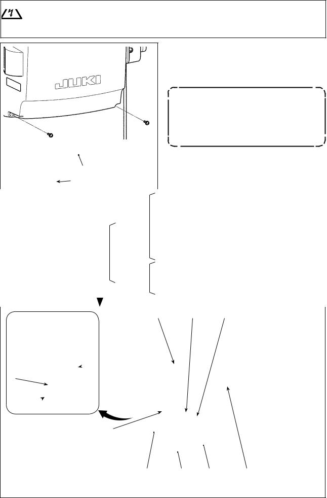
2-10. Handling the cords
DANGER :
1.To prevent personal injuries caused by electric shock hazards or abrupt start of the sewing machine, carry out the work after turning OFF the power switch and a lapse of 5 minutes or more.
2.To prevent accidents caused by unaccustomed work or electric shock, request the electric expert or engineer of our dealers when adjusting the electrical components.
1)Bring the cords under the table into the control box.

 2) Put the cord brought into the control box through
cord exit plate and fix cable clip band .
Arrange the cord so that it is not tensed or hitched even when the machine head  is tilted. (See A section.)
A
3) Install control box cover with four setscrews .
For the purpose of preventing the cord breakage, take care not to allow the cords to be caught between the control box and control box cover when attaching the latter.
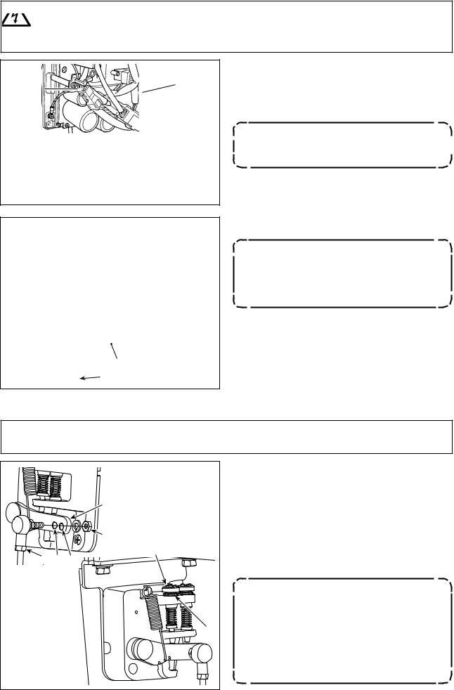
2-11. Attaching the connecting rod
WARNING :
To protect against possible personal injury due to abrupt start of the machine, be sure to start the following work after turning the power off and a lapse of 5 minutes or more.
|
|
|
|
B A |
|
|
|
|
|
1)Fix connecting rod to installing hole B of pedal lever with nut .
2)Installing connecting rod to installing hole A will lengthen the pedal depressing stroke, and the pedal operation at a medium speed will be easier.
3)The pressure increases as you turn reverse depressing regulator screw in, and decreases as you turn the screw out.
1.If the screw is excessively loosened, the spring will come off. Loosen the screw to such an extent that the top of the screw can be observed from the case.
2.Whenever you have adjusted the
screw, be sure to secure the screw by tightening metal nut to prevent the screw from loosening.
– 10 –
2-12. Adjustment of the pedal
WARNING :
Turn OFF the power before starting the work so as to prevent accidents caused by abrupt start of the sewing machine.
|
|
2-12-1. Installing the connecting rod |
|
|
|
1) |
Move pedal to the right or left as illustrated by the |
|
|
|
arrows so that motor control lever and connecting rod |
|
|
|
are straightened. |
|
|
2-12-2. Adjusting the pedal angle |
|
|
|||
|
|
1) |
The pedal tilt can be freely adjusted by changing the |
|
|
length of the connecting rod . |
|
|
|
|
|
|
|
2) |
Loosen adjust screw , and adjust the length of connect- |
|
|
|
ing rod . |

2-13. Pedal operation
A
B
C
D
E
The pedal is operated in the following four steps :
1)The machine runs at low sewing speed when you lightly depress the front part of the pedal. B
2)The machine runs at high sewing speed when you further depress the front part of the pedal. A (If the automatic reverse feed stitching has been preset, the machine runs at high speed after it completes reverse feed stitching.)
3)The machine stops (with its needle up or down) when you reset the pedal to its original position. C
4)The machine trims threads when you fully depress the back part of the pedal. E
*When the auto-lifer (AK device) is used, one more operating switch is provided between the sewing machine stop switch and thread trimming switch.
The presser foot goes up when you lightly depress the back part of the pedal D, and if you further depress the back part, the thread trimmer is actuated.
When starting sewing from the state that the presser foot has been lifted with the Auto-lifter and you depress the back part of the pedal, the presser foot only comes down.
•If you reset the pedal to its neutral position during the automatic reverse feed stitching at seam start, the machine stops after it completes the reverse feed stitching.
•The machine will perform normal thread trimming even if you depress the back part of the pedal immediately following high or low speed sewing.
•The machine will completely perform thread trimming even if you reset the pedal to its neutral position immediately after the machine started thread trimming action.
–11 –

2-14. Lubrication
WARNING :
1.Do not connect the power plug until the lubrication has been completed so as to prevent accidents due to abrupt start of the sewing machine.
2.To prevent the occurrence of an inflammation or rash, immediately wash the related portions if oil adheres to your eyes or other parts of your body.
3.If oil is mistakenly swallowed, diarrhea or vomitting may occur. Put oil in a place where children cannot reach.
|
|
Fill the oil tank with oil for hook lubrication before |
|
|
|
operating the sewing machine. |
|
|
|
1) Remove oil hole cap and fill the oil tank with |
|
|
|
JUKI NEW DEFRIX OIL No.1 (part number : MD- |
|
|
|
FRX1600C0) or JUKI CORPORATION GENUINE |
|
|
|
OIL 7 (part number : 40102087) using the oiler |
|
|
|
supplied with the machine. |
|
|
|
2) Fill the oil tank with the oil until the top end of |
|
|
A |
oil amount indicating rod comes between the |
|
|
upper engraved marker line A and the lower |
||
|
|||
|
engraved marker line B of oil amount indicating |
||
|
|
||
|
B |
window . |
|
|
If the oil is filled excessively, it will leak from the |
||
|
|
||
|
|
air vent hole in the oil tank or proper lubrication |
|
|
|
will be not performed. In addition, when the oil is |
|
|
|
vigorously filled, it may overflow from the oil hole. |
|
|
|
So, be careful. |
|
|
|
3) When you operate the sewing machine, refill oil if |
|
|
|
the top end of oil amount indicating rod comes |
|
|
|
down to the lower engraved marker line B of oil |
|
|
|
amount indicating window . |
1.When you use a new sewing machine or a sewing machine after an extended period of disuse, use the sewing machine after performing break-in at 2,000 sti/min or less.
2.For the oil for hook lubrication, purchase JUKI NEW DEFRIX OIL No. 1 (part number : MDFRX1600C0) or JUKI CORPORATION GENUINE OIL 7 (part number : 40102087).
3.Be sure to lubricate clean oil.
4.Do not operate the machine with the oil hole cap removed. Never remove cap from the oil inlet in any case other than oiling. In addition, take care not to lose it.
– 12 –
2-15. How to use the operation panel (Basic explanation)
2-15-1. Selection of the language (operation to be done at first)
Select the language to be displayed on the operation panel when you turn ON the power to your sewing machine for the first time after the purchase. Note that, if you turn the power OFF without selecting the language, the language selection screen will be displayed every time you turn ON the power to the sewing machine.
Turning ON the power switch
Be aware that the needle bar moves automatically. The needle bar can also be set so that it does not move automatically. Refer to "4-5. List of memory switch data" p. 48 for details.
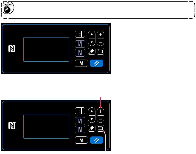
When you turn ON the power switch, the language selection screen is displayed.
<Language selection screen>
Selecting the language
Select the desired language to be displayed on the operation panel with
 . Then, press
  .
.
This confirms your language selection.
The language to be displayed on the operation panel can be changed using the memory switch U406. Refer to "4-5. List of memory switch data" p. 48 for details.
– 13 –
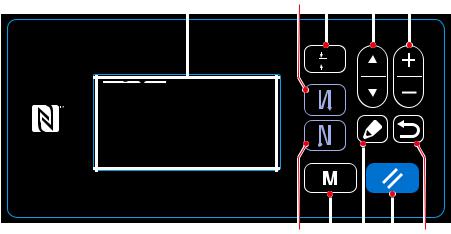
2-15-2. Names and functions of the panel keys
|
|
|
|
|
|
|
|
|
|
|
|
|
|
|
|
|
|
|
|
|
|
|
|
|
|
|
|
|
|
|
|
|
|
|
|
|
|
|
|
|
|
|
|
|
|
|
|
|
|
|
|
|
|
|
|
|
|
|
|
|
|
|
|
|
|
|
|
|
|
|
|
|
|
|
|
|
|
|
|
|
|
|
|
|
|
|
|
|
|
|
|
|
|
|
|
|
|
|
|
|
|
|
|
|
|
|
|
|
|
|
|
|
|
|
|
|
|
|
|
|
|
|
|
|
|
|
|
|
|
|
|
|
|
|
|
|
|
|
|
|
|
|
|
|
|
|
|
|
|
|
|
|
|
|
|
|
|
|
|
|
|
|
|
|
|
|
|
|
|
|
|
|
|
|
|
|
|
|
|
|
|
|
|
|
|
|
|
|
|
|
|
|
|
|
|
|
|
|
|
|
|
|
|
|
|
|
|
|
|
|
|
|
|
|
|
|
|
|
|
|
|
|
|
|
|
|
|
|
|
|
|
|
|
|
|
|
|
|
|
|
|
|
|
|
|
|
|
|
|
|
|
|
|
|
|
|
|
|
|
|
|
|
|
|
|
|
|
|
|
|
|
|
|
|
|
|
|
|
|
|
|
|||
|
|
|
|
|
|
|
||||||||||||
|
|
|
|
|
|
|
|
|
|
|
|
|
|
|
|
|
|
|
|
Switch/display |
|
|
Description |
|
|
|
|
|
|||||||||
|
|
|
|
|
|
|
|
|
|
|
|
|
|
|
|
|
|
|
|
Item selection key |
This key is used for changing over the screen display or for displaying the edit screen. |
||||||||||||||||
|
|
Refer to the explanation of each screen for details. |
|
|
|
|
|
|||||||||||
|
|
|
|
|
|
|
|
|
|
|
|
|
|
|
|
|
|
|
|
Data change key |
This key is used for changing the currently-displayed pattern number or for changing the |
||||||||||||||||
|
|
numeric value shown on the counter. Refer to the explanation of each screen for details. |
||||||||||||||||
|
|
|
|
|
|
|
|
|
|
|
|
|
|
|
|
|
|
|
|
Reverse feed stitch- |
This key is used for selecting whether or not the reverse feed stitching is performed at the |
||||||||||||||||
|
ing (at start) key |
beginning of sewing. |
|
|
|
|
|
|||||||||||
|
|
The reverse feed stitching (at start) edit screen is displayed by keeping this key held |
||||||||||||||||
|
|
pressed for one second. |
|
|
|
|
|
|||||||||||
|
|
|
|
|
|
|
|
|
|
|
|
|
|
|
|
|
|
|
|
Reverse feed stitch- |
This key is used for selecting whether or not the reverse feed stitching is performed at the |
||||||||||||||||
|
ing (at end) key |
end of sewing. |
|
|
|
|
|
|||||||||||
|
|
The reverse feed stitching (at end) edit screen is displayed by keeping this key held |
||||||||||||||||
|
|
pressed for one second. |
|
|
|
|
|
|||||||||||
|
|
|
|
|
|
|
|
|
|
|
|
|
|
|
|
|
|
|
|
Edit key |
This key is used for displaying the edit screen, item section screen or details screen. |
||||||||||||||||
|
|
|
|
|
|
|
|
|
|
|
|
|
|
|
|
|
|
|
|
Return key |
This key is used for returning the screen to the previous one. |
||||||||||||||||
|
|
|
|
|
|
|
|
|
|
|
|
|
|
|
|
|
|
|
|
Pitch key |
This key is used for displaying the pitch entry screen. |
|
|
|
|
|
|||||||||||
|
|
|
|
|
|
|
|
|
|
|
|
|
|
|
|
|
|
|
|
Reset key |
This key is used for resetting the error, for resetting the counter and for initial setting of |
||||||||||||||||
|
|
the feed. |
|
|
|
|
|
|||||||||||
|
|
The operation panel is placed in the simple-lock state by keeping this key held pressed for |
||||||||||||||||
|
|
one second. The panel is released from the lock state by operating this key in the same |
||||||||||||||||
|
|
manner again. |
|
|
|
|
|
|||||||||||
|
|
Refer to "8-7-1. Simple lock" p. 99. |
|
|
|
|
|
|||||||||||
|
|
|
|
|
|
|
|
|
|
|
|
|
|
|
|
|
|
|
|
Mode key |
This key is used for displaying the mode screen. |
|
|
|
|
|
|||||||||||
|
|
The user level is displayed by operating this key in the normal manner. |
||||||||||||||||
|
|
The serviceperson level is displayed by keeping the key held pressed for three seconds. |
||||||||||||||||
|
|
|
|
|
|
|
|
|
|
|
|
|
|
|
|
|
|
|
|
Liquid crystal dis- |
Each screen is displayed on this LCD. |
|
|
|
|
|
|||||||||||
|
play section |
|
|
|
|
|
|
|
|
|
|
|
|
|
|
|
|
|
|
|
|
|
|
|
|
|
|
|
|
|
|
|
|
|
|
|
|
* Confirmation of data
Change in the pattern number is confirmed at the moment Data change key is pressed.
For the setting items of the memory switch and pattern number, the setting is changed by pressing Data change key and confirmed by pressing Return key .
The new setting of data of a setting item is also confirmed by selecting other setting item with Item selection key after making a change.
– 14 –

2-15-3. Basic operation
Turning ON the power switch
Selecting a sewing pattern
<Sewing screen>
Starting sewing
When you turn ON the power switch, the welcome screen is displayed.
The sewing screen is displayed.
Select a sewing pattern.
Refer to "4-2. Sewing patterns" p.
30 for details.
Set up functions for the selected sewing pattern.
Refer to "4-2-3. Editing the sewing patterns" p. 33 and "4-2-4. List of pattern functions" p. 35 for details.
When you depress the pedal, the sewing machine starts sewing.
Refer to "2-13. Pedal operation" p. 11.
– 15 –
3. PREPARATION BEFORE SEWING
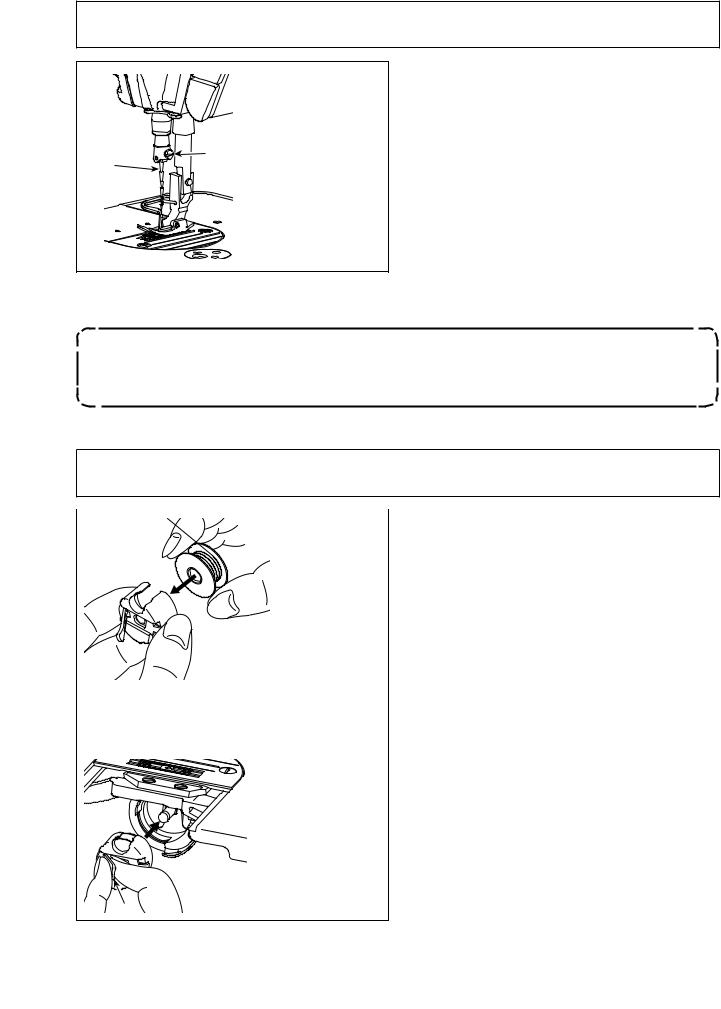
3-1. Attaching the needle
WARNING :
Turn OFF the power before starting the work so as to prevent accidents caused by abrupt start of the sewing machine.
|
|
D |
B |
|
|
C |
A |
|
|
Use the specified needle for the machine. Use the proper needle in accordance with the thickness of thread used and the kinds of the materials.
1)Turn the handwheel until the needle bar reaches the highest point of its stroke.
2)Loosen screw , and hold needle with its indented part A facing exactly to the right in direction B.
3)Insert the needle fully into the hole in the needle bar in the direction of the arrow until the end of hole is reached.
4)Securely tighten screw .
5)Check that long groove C of the needle is facing exactly to the left in direction D.
When polyester filament thread is used, if the indented part of the needle is tilted toward operator's side, the loop of thread becomes unstable. As a result, hangnail of thread or thread breakage may occur. For the thread that such phenomenon is likely to occur, it is effective to attach the needle with its indented part slightly slanting on the rear side.
3-2. Removing/fitting the bobbin case
WARNING :
Turn OFF the power before starting the work so as to prevent accidents caused by abrupt start of the sewing machine.
|
|
1) |
Turn the handwheel to lift the needle above the |
|
|
|
|
throat plate. |
|
|
2) |
Install the bobbin in the bobbin case so that the |
||
|
|
|
thread wound direction is clockwise. |
|
|
3) |
Pass the thread through thread slit A of the bob- |
||
|
A |
bin case, and pull the thread in direction C. By |
||
|
|
|
so doing, the thread will pass under the tension |
|
|
|
|
spring and come out from notch B. |
|
|
4) |
Check that the bobbin rotates in the direction of |
||
B |
|
|
the arrow when thread is pulled. |
|
5) |
Pinching latch D of the bobbin case with fingers, |
|||
|
||||
|
|
|
fit the bobbin case in the hook. |
|
C |
|
|
|
|
D
– 16 –
3-3. Winding the bobbin thread
|
|
|
|
A |
|
|
|
|
D |
|
|
|
|
|
|
B |
|
|
C |
|
|
|
|
|
|
|
|
E |
|
|
|
|
|
|
|
|
F |
|
|
|
|
|
|
|
1)Insert the bobbin deep into the bobbin winder spindle until it will go no further.
2)Pass the bobbin thread pulled out from the spool rested on the right side of the thread stand following the order as shown in the figure on the left. Then, wind clockwise the end of the bobbin thread on the bobbin several times. (In case of the aluminum bobbin, after winding clockwise the end of the bobbin thread, wind counterclockwise the thread coming from the bobbin thread tension several times to wind the bobbin thread with ease.)
3)Press the bobbin winding lever in the direction of A and start the sewing machine. The bobbin rotates in the direction of B and the bobbin thread is wound up. The bobbin winder spindle automatically as soon as the winding is finished.
4)Remove the bobbin and cut the bobbin thread with the thread cut retainer .
5)When adjusting the winding amount of the bobbin thread, loosen setscrew and move bobbin winding lever to the direction of C or D. Then tighten setscrew .
To the direction of C : Decrease To the direction of D : Increase
6)In case that the bobbin thread is not wound evenly on the bobbin, remove the handwheel, loosen screw and adjust the height of bobbin thread tension .
•It is the standard that the center of the bobbin is as high as the center of thread tension disk .
•Adjust the position of thread tension disk to the direction of E when the winding amount of the bobbin thread on the lower part of the bobbin is excessive and to the direction F when the winding amount of the bobbin thread on the upper part of the bobbin is excessive.
After the adjustment, tighten screw .
7)To adjust the tension of the bobbin winder, turn the thread tension nut .
1.When winding the bobbin thread, start the winding in the state that the thread between the bobbin and thread tension disk is tense.
2.When winding the bobbin thread in the state that sewing is not performed, remove the needle thread from the thread path of thread take-up and remove the bobbin from the hook.
3.There is the possibility that the thread pulled out from the thread stand is loosened due to the influence (direction) of the wind and may be entangled in the handwheel. Be careful of the direction of the wind.
– 17 –
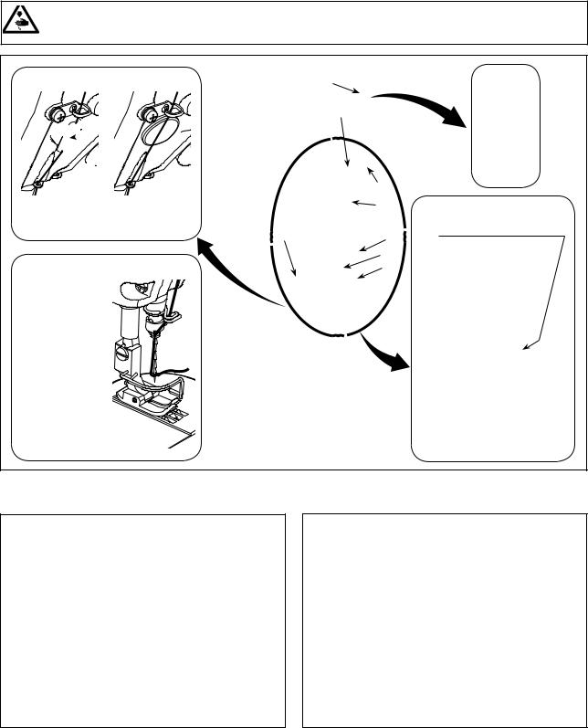
3-4. Threading the machine head
WARNING :
Turn OFF the power before starting the work so as to prevent accidents caused by abrupt start of the sewing machine.
[NB type] |
[0B type] |

 B
B
(Note)
Be sure to pass the thread through the section B.
[S type] |
[H type] |


(Note)
Do not pass this thread through section A.
A
3-5. Thread tension
B A
D C
3-5-1. Adjusting the needle thread tension
1)Turn thread tension No. 1 nut clockwise (in direction A), to shorten the thread length remaining
on the needle after thread trimming or counterclockwise (in direction B), to lengthen the thread length.
2)Turn thread tension nut clockwise (in direction C) to increase or counterclockwise (in direction D) to reduce the needle thread tension.
E |
F |
3-5-2. Adjusting the bobbin thread tension
1)Turn tension adjusting screw clockwise (in direction E) to increase or counterclockwise (in direction F) to reduce the bobbin thread tension.
– 18 –
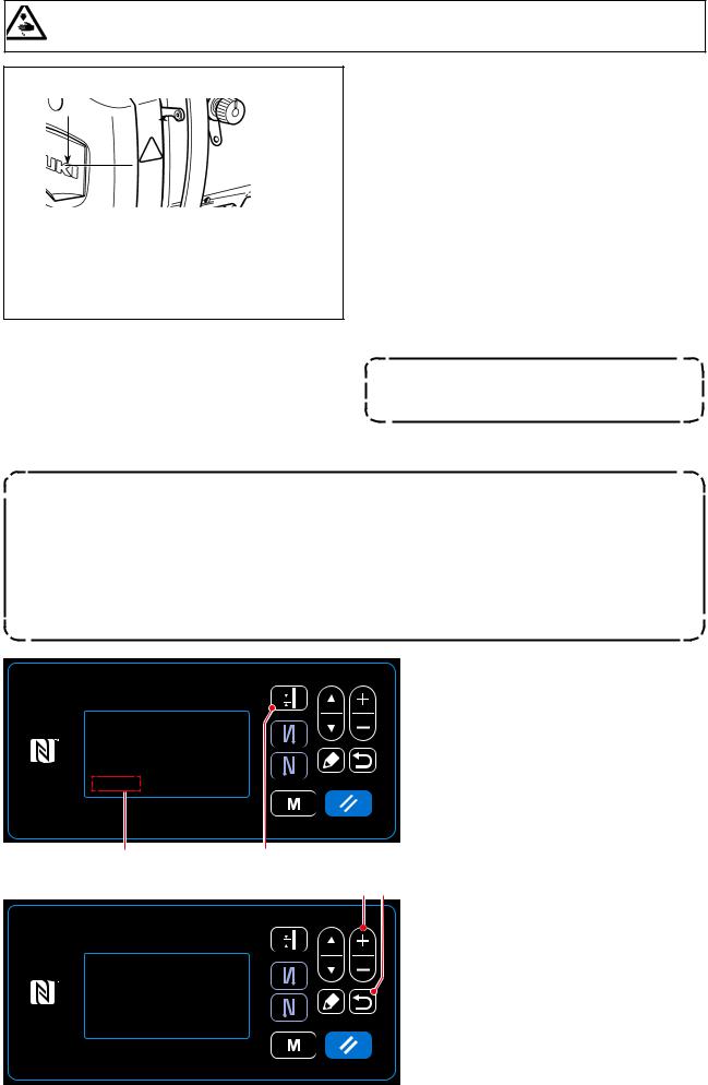
3-6. Presser foot pressure
WARNING :
Turn OFF the power before starting the work so as to prevent accidents caused by abrupt start of the sewing machine.
BA

 C
C 
1)Loosen nut . As you turn presser spring regulator clockwise (in direction A), the presser foot pressure will be increased.
2)As you turn the presser spring regulator count- er-clockwise (in direction B), the pressure will be decreased.
3)After adjustment, tighten nut .
The standard value of the height C of presser spring regulator is as follows :
• S type : 31.5 to 29 mm
(approx. 40 to 45 N / 4 to 4.5 kg)
• H type : 31.5 to 28 mm
(approx. 50 to 60 N / 5 to 6 kg)
To avoid personal injury, never put your fingers under the presser foot.
3-7. Adjusting the stitch length
1.There may be the cases where the feed amount of the operation panel and the actual sewing pitch are different from each other in case of the use in the state other than the standard delivery or material used. Compensate the pitch in accordance with the sewing product.
2.Be aware that interference between the throat plate and feed dog can occur depending on the gauge used. Be sure to check the clearance in the gauge to be used. (The clearance must be 0.5 mm or more.)
3.When you have changed the stitch length, feed dog height or feed timing, run the sewing machine at a low speed to make sure that the gauge does not interfere with the changed part.
Stitch length is displayed in section A on the panel. (Example of display : 2.50 mm)
[How to adjust]
1) Display the stitch pitch entry screen by pressing  .
.
A |
|
2) The value displayed is changed by press-
ing  . (In increments of 0.05
mm ; Input range : -5.00 to 5.00)
3) Confirm your entry by pressing  . Then, the sewing screen is displayed.
– 19 –

3-8. Changing the sewing speed
The sewing speed is displayed in section A on the panel. (Example of display : 4,000 sti/min)
[How to change]
1) Display the sewing data edit screen by pressing  .
.
A |
|
2) Display "S047" by pressing .
3) Change the sewing speed as desired by
pressing |
. |
|
4) Confirm your entry by pressing |
. |
|
Then, the sewing screen is displayed.
– 20 –
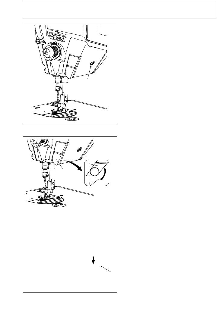
3-9. LED hand light
WARNING :
In order to protect against personal injury due to unexpected start of the sewing machine, never bring hands near the needle entry area or place foot on the pedal during the adjustment of intensity of the LED.
|
*This LED is intended to improve operability of the sewing machine and is not intended for maintenance.
The sewing machine is provided as standard with an LED light which illuminates the needle entry area. Intensity adjustment and turn-off of the light is carried out by pressing switch . Every time the switch is pressed, the light is adjusted in intensity in five steps and is turned off in turn.
[Change of intensity]
1 ...... 4 5 1 Bright ...... Dim Off Bright
In this way, every time the switch is pressed, the hand lamp status is changed in repetition.
3-10. Reverse feed stitching
|
Fig. 1 |
|
[One-touch type reverse feed stitching mechanism]
The one-touch type reverse feed switch is pressed, the machine performs reverse feed stitching.
The machine resumes normal feed stitching the moment the switch lever is released.
[Reverse feed stitching by means of the reverse feed lever]
Length of the seam sewn by feeding the material in the normal or reverse direction of feed can be controlled by operating reverse feed lever .
[Adjusting the position of one-touch type reverse feed switch]
One-touch type reverse feed switch can be used at two different positions by turning it. (Fig. 1)
– 21 –

3-11. Custom switch |
|
|
|
|
|
|
Various operations can be carried out by operating |
|
|
|
custom switch . |
|
|
|
* Various operations can be allocated also to one- |
|
|
|
touch type reverse feed switch . |
|
|
|
|
|
|
|
|
A |
B |
|
|
1) |
Keep |
held pressed for six sec- |
|
onds. |
|
2) |
Select "12. Optional I/O setting" with |
|
 . Then, press
  .
.
3) To set up a function of custom switch :
|
|
|
[Description of operations of the custom switch] |
||
|
Abbre- |
Function item |
|
viation |
|
|
|
|
0 |
noP |
No function |
1 |
HS |
Needle up / down compensating stitching |
2 |
bHS |
Back compensating stitching |
3 |
EbT |
Function of canceling once reverse feed stitching at |
|
|
the end of sewing |
4 |
TSW |
Thread trimming function |
5 |
FL |
Presser foot lifting function |
6 |
oHS |
One stitch compensating stitching |
7 |
SEbT |
Function of cancel of reverse feed stitching at start/ |
|
|
end |
8 |
Ed |
Material edge sensor input |
9 |
LinH |
Function of prohibiting depressing front part of pedal |
10 |
TinH |
Function of prohibiting thread trimming output |
11 |
LSSW |
Low speed command input |
12 |
HSSW |
High speed command input |
13 |
USW |
Needle lifting function |
14 |
bT |
Reverse feed stitching switch input |
15 |
SoFT |
Soft start switch input |
16 |
oSSW |
One-shot speed command switch input |
17 |
bKoS |
Backward one-shot speed command switch input |
18 |
SFSW |
Safety switch input |
19 |
AUbT |
Automatic reverse feed stitching cancellation/addition |
|
|
switch |
20 |
CUnT |
Sewing counter input |
21 |
OTSW |
One-touch type changeover switch |
Select input number A with |
. |
|
Enter "3" with |
. |
|
Select function item B with |
. |
|
Enter the function item with |
. |
|
Display HIGH/LOW selection with |
|
|
, and enter "LOW" with |
|
|
.
4)To set up a function of one-touch type reverse feed switch :
Select input number A with |
. |
|
Enter "1" with |
. |
|
Select function item B with |
. |
|
Enter the function item with |
. |
|
Display HIGH/LOW selection with |
|
|
, and enter "LOW" with
.
– 22 –
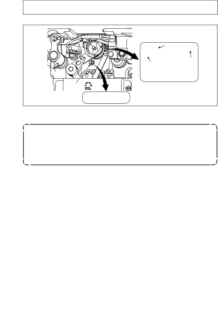
3-12. Adjusting the amount of oil (oil splashes) in the hook
WARNING :
Be extremely careful about the operation of the machine since the amount of oil has to be checked by turning the hook at a high speed.
3-12-1. Adjusting the amount of oil in the hook
|
|
|
|
|
|
|
|
|
|
|
|
Decrease |
Increase |
|
Tighten (turn clockwise) oil amount adjustment screw to increase the amount of oil in the hook, or loosen (turn counterclockwise) to decrease it.
[When using RP hook (hook for dry head) for DDL-9000C-SMS type]
1.Remove hook driving shaft oil wick setscrew and attach hook driving shaft stopper screw(part number : 11079506) and rubber ring (part number : RO036080200).
2.Loosen oil amount adjustment screw up to the minimum so as to reduce the oil amount in
the hook. However, do not completely stop the oil and be careful not to allow oil adjustment screw to come off.
3.Never drain the oil in the oil tank even when RP hook (hook for dry head) is used.
– 23 –
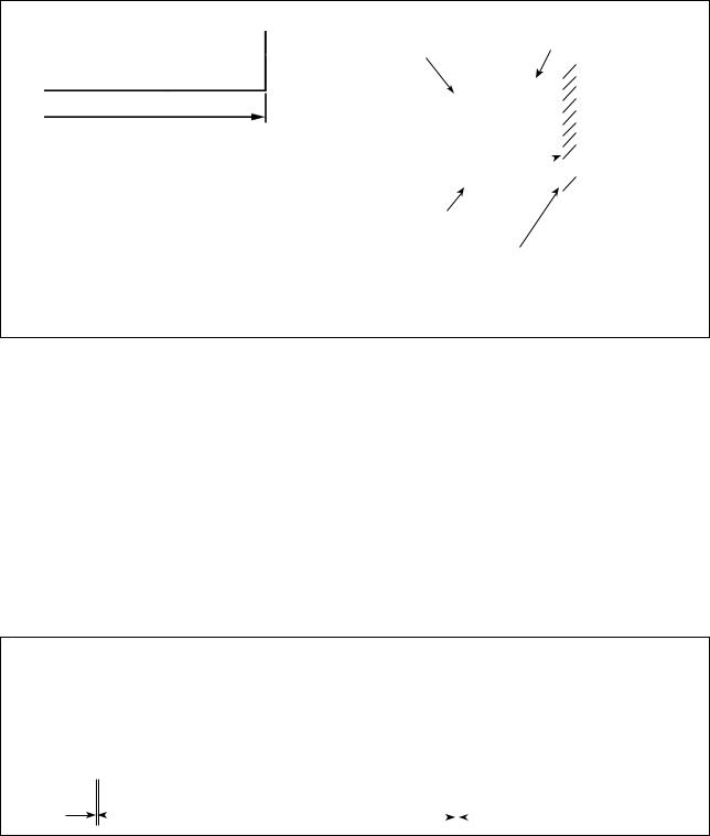
3-12-2. How to confirm the amount of oil (oil splashes)
Amount of oil (oil splashes) confirmation paper
Approx. 25 mm
Approx. 70 mm
* Use any paper available regardless of the material.
Position to confirm the amount of oil (oil splashes)
Hook |
Hook driving shaft front bushing |
|
3 to 10 mm
Bed

Oil splashes confirmation paper
Closely fit the paper against the wall surface of the bed.
* Place the amount of oil (oil splashes) confirmation paper under the hook and keep it from the hook by 3 to 10 mm to confirm the amount.
*When carrying out the procedure described below in 2), confirm the state that the needle thread from the thread take-up lever to the needle and the bobbin thread are removed, the presser foot is lifted and the slide plate is removed. At this time, take extreme caution not to allow your fingers to come in contact with the hook.
1)If the machine has not been sufficiently warmed up for operation, make the machine run idle for approximately three minutes. (Moderate intermittent operation)
2)Place the amount of oil (oil splashes) confirmation paper under the hook while the sewing machine is in operation.
3)Confirm that oil exists in the oil tank.
4)Confirmation of the amount of oil should be completed in five seconds. (Check the period of time with a watch.)
3-12-3. Sample showing the appropriate amount of oil
Appropriate amount of oil (small) |
Appropriate amount of oil (large) |
Splashes of oil from the hook |
Splashes of oil from the hook |
• DDL-9000C-SMS : 0.5 to 1 mm |
|
|
|
|
|
• DDL-9000C-SMS : 1 to 1.5 mm |
• DDL-9000C-SSH : 1 to 3 mm |
|
|
|
|
|
• DDL-9000C-SSH : 2 to 4 mm |
|
||||||
|
|
|
|
|
|
|
1)The state given in the figure above shows the appropriate amount of oil (oil splashes). It is necessary to finely adjust the amount of oil in accordance with the sewing processes. However, do not excessively
increase/decrease the amount of oil in the hook. (If the amount of oil is too small, the hook will be seized (the hook will be hot). If the amount of oil is too much, the sewing product may be stained with oil.)
2)Check the oil amount (oil splashes) three times (on the three sheets of paper), and adjust so that it should not change.
–24 –
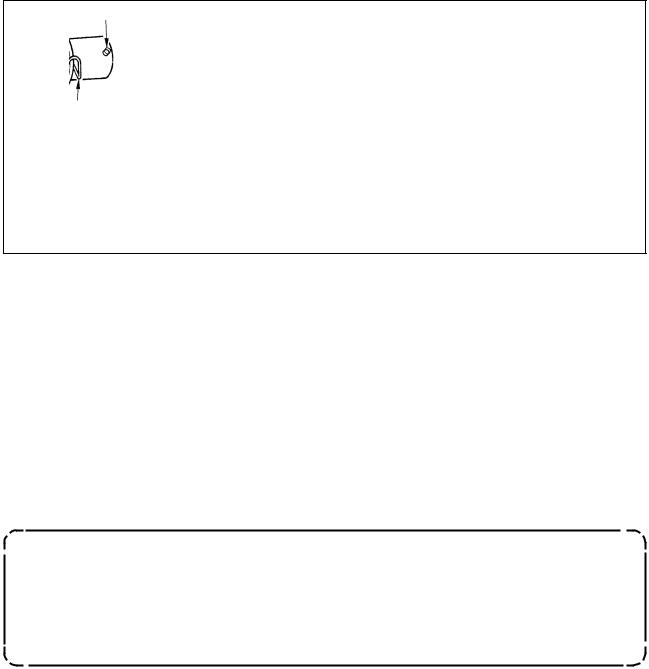
3-13. Adjusting the thread take-up spring and the thread take-up stroke
|
|
|
[DDL-9000C-SMS] |
[DDL-9000C-SSH] |
||
|
|
|
||||
|
|
|
|
C D |
|
|
|
|
|
|
|
|
|
|
|
|
|
|
|
|
|
|
|
|
|
|
|
|
|
|
|
|
|
|
F |
E |
A |
|
A |
|
|
|
||||||
|
|
|
B |
|
B |
|
|
GH |
|
|
|
|
|
|
|
|
|
|
||
(1)Adjusting the stroke of thread take-up spring
1) Loosen setscrew .
2) Turn tension post clockwise (in direction A), the stroke of the thread take-up spring will be increased, and turn the post counterclockwise (in direction B), the stroke will be decreased.
(2)Adjusting the pressure of thread take-up spring
1)Loosen setscrew , and remove thread tension (asm.) .
2)Loosen tension post setscrew .
3)Turn tension post clockwise (in direction A), the pressure will be increased, and turn the post counterclockwise (in direction B), the pressure will be decreased.
* Standard state of the thread take-up spring
The engraved marker line on the machine arm is almost aligned with the top of thread take-up spring. (It is necessary to adjust in accordance with materials and processes.)
To check how the thread take-up spring works, draw out the needle thread in direction F after having adjusted the thread take-up spring pressure to check whether the thread take-up spring exerts force to the thread up to the last moment (state G) just before the thread comes out from E. If the spring fails to exert force to the spring until the last moment (state H), decrease the thread take-up spring pressure. In addition, the stroke of the thread take-up spring is excessively small, the spring does not work properly. For the general fabrics, a stroke of 10 to 13 mm is proper.
(3) Adjusting the thread take-up stroke
1)When sewing heavy-weight materials, move thread guide to the left (in direction C) to increase the length of thread pulled out by the thread take-up.
2)When sewing light-weight materials, move thread guide to the right (in direction D) to decrease the length of thread pulled out by the thread take-up.
* Standard state of the thread guide
•DDL-9000C-SMS : Marker line on the thread guide aligns with the center of the setscrew.
•DDL-9000C-SSH : Marker line on the thread guide aligns with the center of the marker line on the ma-
chine arm.
– 25 –
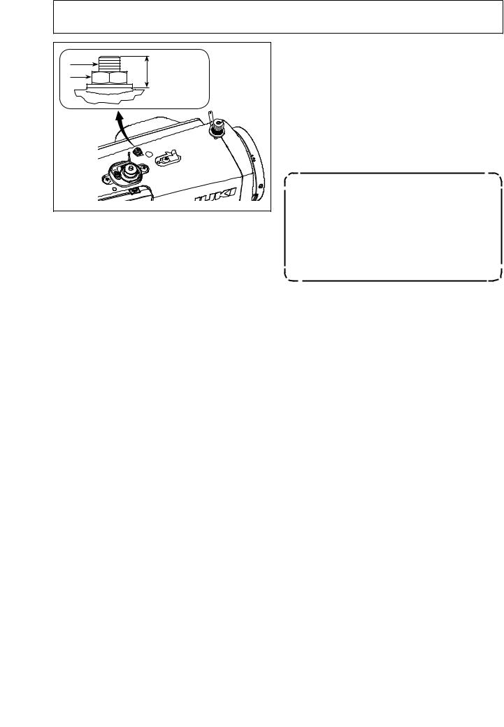
3-14. Micro-lifting mechanism of the presser foot
WARNING :
Turn OFF the power before starting the work so as to prevent accidents caused by abrupt start of the sewing machine.
|
Approx. 9 mm |
|
|
||
|
When sewing velvet or the like which is fluffy, slippage of material or damage of material is reduced by using screw for presser foot micro-lifting. Lower the presser foot and set the state that the feed dog is lower than the throat plate.
Gradually tighten screw for presser foot micro-lift- ing in the state that nut is loosened, finely adjust the position of the presser foot until it matches the material, and fix it with nut .
When the presser foot micro-lifting mechanism is not used, adjust the height of screw so that it is higher by approximately 9 mm than the sewing machine. If the sewing machine is operated in the state that the microlifting mechanism is working, sufficient feed force cannot be obtained.
– 26 –
Loading...