


 Loading...
ENGLISH
DDL-8700A-7
Instruction Manual
CONTENTS
!. SPECIFICATIONS...................................................................................... |
1 |
||
@. SET-UP....................................................................................................... |
3 |
||
1. |
Installation................................................................................................................... |
3 |
|
2. |
Installing the pedal sensor........................................................................................ |
4 |
|
3. |
Installing the power switch........................................................................................ |
4 |
|
4. Attaching the connecting rod.................................................................................... |
6 |
||
5. |
Winding the bobbin thread........................................................................................ |
7 |
|
6. Adjusting the height of the knee lifter...................................................................... |
8 |
||
7. |
Installing the thread stand......................................................................................... |
8 |
|
8. |
Lubrication.................................................................................................................. |
9 |
|
9. Adjusting the amount of oil (oil splashes)............................................................... |
9 |
||
10. Attaching the needle............................................................................................... |
11 |
||
11. Setting the bobbin into the bobbin case.............................................................. |
12 |
||
12. Adjusting the stitch length.................................................................................... |
12 |
||
13. |
Presser foot pressure............................................................................................ |
12 |
|
14. |
Hand lifter................................................................................................................ |
12 |
|
15. Adjusting the height of the presser bar............................................................... |
13 |
||
16. |
Threading the machine head................................................................................. |
13 |
|
17. |
Thread tension........................................................................................................ |
14 |
|
18. |
Thread take-up spring............................................................................................ |
14 |
|
19. Adjusting the thread take-up stroke..................................................................... |
14 |
||
20. |
Needle-to-hook relationship.................................................................................. |
15 |
|
21. |
Height of the feed dog............................................................................................ |
15 |
|
22. |
Tilt of the feed dog................................................................................................. |
16 |
|
23. Adjusting the feed timing...................................................................................... |
16 |
||
24. |
Cunter knife............................................................................................................. |
17 |
|
25. |
Pedal pressure and pedal stroke.......................................................................... |
17 |
|
26. Adjustment of the pedal......................................................................................... |
18 |
||
#. FOR THE OPERATOR............................................................................. |
19 |
||
1. |
Operating procedure of the sewing machine........................................................ |
19 |
|
2. |
Built-in panel of the machine head......................................................................... |
21 |
|
3. |
Operating procedure of the sewing pattern........................................................... |
22 |
|
4. |
One-touch setting..................................................................................................... |
24 |
|
5. |
Production support function................................................................................... |
25 |
|
6. |
Setting of functions.................................................................................................. |
28 |
|
7. |
Function setting list................................................................................................. |
29 |
|
8. |
Detailed explanation of selection of functions...................................................... |
33 |
|
9. Automatic compensation of neutral point of the pedal sensor........................... |
43 |
||
10. |
Selection of the pedal specifications................................................................... |
43 |
|
11. Setting of the auto lifter function.......................................................................... |
44 |
|
12. |
Selecting procedure of the key-lock function...................................................... |
45 |
13. |
Removing the rear cover....................................................................................... |
46 |
14. |
Connection of the pedal of standing-work machine........................................... |
48 |
15. |
External input / output connector......................................................................... |
48 |
16. |
Connection of the material end sensor................................................................ |
49 |
17. |
Initialization of the setting data............................................................................. |
50 |
$. MAINTENANCE....................................................................................... |
51 |
|
1. |
Replacing the fuse.................................................................................................... |
51 |
2. Adjusting the machine head.................................................................................... |
52 |
|
3. |
Connector layout drawing....................................................................................... |
53 |
4. |
Error codes............................................................................................................... |
54 |
ii

!. SPECIFICATIONS
Supply voltage |
Single phase 100 to 120V |
3-phase 200 to 240V |
Single phase 220 to 240V |
|
|
|
|
Frequency |
50Hz/60Hz |
50Hz/60Hz |
50Hz/60Hz |
Operating environ- |
Temperature : 5 to 35˚C |
Temperature : 5 to 35˚C |
Temperature : 5 to 35˚C |
ment |
Humidity 35 - 85 % or less |
Humidity 35 - 85 % or less |
Humidity 35 - 85 % or less |
Input |
210VA |
210VA |
210VA |
DDL-8700A  - 7
- 7
S : Medium-weight materials H : Heavy-weight materials
|
DDL-8700AS-7 |
DDL-8700AH-7 |
|
|
|
|
|
Max. sewing speed |
5,000 sti/min |
4,000 sti/min |
|
|
|
|
|
Thread trimming speed |
300 sti/min |
300 sti/min |
|
Stitch length |
4mm |
5mm |
|
|
|
|
|
Presser foot lift |
13 mm |
13 mm |
|
(by knee lifter) |
|||
|
|
||
Needle *1 |
DB x 1 (#14) #9 to 18 |
DB x 1 (#21) #20 to 23 |
|
Lubricating oil |
JUKI MACHINE OIL #7 |
JUKI MACHINE OIL #7 |
•The sewing speed will vary depending on the sewing conditions.
•The sewing speed preset at the time of shipping ...... AS-7 : 4,000sti/min.
...... AH-7 : 3,500sti/min.
*1 : Needle used depends on the destination.
|
- Equivalent continuous emission sound pressure level (LpA) at the workstation : |
Noise |
A-weighted value of 79.5 dB; (Includes KpA = 2.5 dB); according to ISO 10821- C.6.2 -ISO |
|
11204 GR2 at 4,000 sti/min. |
|
|
– –

bottom surface, depth 20
– –
depth 10
2-ø3.4 bottom surface, depth 10
(Hinge side only)
TABLE OF DRAWING
@. SET-UP
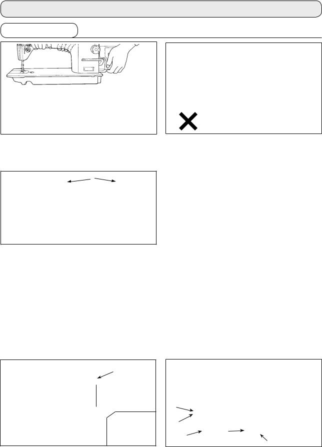
1. Installation
1)Carry the sewing machine with two persons as
shown in the figure above.
(Caution) Do not hold the handwheel.
|
8 |
3 |
3 |
|
|
1 |
1 |
2)Do not put protruding articles such as the screwdriver and the like at the location where the sewing machine is placed.
3)The under cover should rest on the four corners of the machine table groove. Mount rubber hinge seat 8 on the table and fix it on the table with a nail.
Needle bar side |
4 |
|
Control box side |
4 |
1 |
|
1 |
||
|
|
|
||
23.5mm |
|
19.5mm |
23mm |
19.5mm |
2 |
|
3 |
2 |
3 |
A |
B |
|
A |
B |
|
|
|
|
|
4)Fix two rubber seats 1 on side A (operator’s side) using nails 2 as illustrated above. Fix two cushion seats 3 on side B (hinged side) using a rubber-based adhesive. Then place under cover 4 on the fixed seats.
6
9
!1
!2
7
5)Fit knee lifter pressing rod 6. Fit hinge 7 into the opening in the machine bed, and fit the machine head to table rubber hinge 8 before placing the machine head on cushions 9 on the four corners.
6)Securely attach head support rod !0to the table until it goes no further.
(Caution) Be sure to install the machine head support bar supplied with the unit.
7)Draw out cable !1of the control box through cable draw-out hole !2to route it to the underside of the sewing machine table.
––
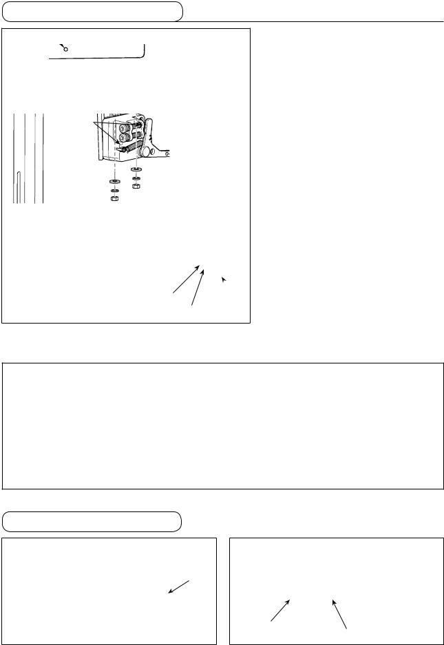
2. Installing the pedal sensor
1
1
Plain  washer Spring Hexagonal washer nat
The explanation applies to the case the pedal sensor is installed on the table for the DDL-8700A-7.
1)Install the pedal sensor on the table by means of mounting bolt asm. 1 supplied with the unit. At this time, insert the nut and washer supplied with the unit as accessories as shown in the figure so that the control box is securely fixed.
2)After the completion of installation of the pedal sensor on the table, place the sewing machine head on the table.
WARNING :
• To protect against personal injury resulting from abrupt start of the sewing machine, be sure to turn the power OFF, unplug the machine and wait for five minutes or more before installing the pedal sensor.
• To prevent damage of device caused by maloperation and wrong specifications, be sure to connect all the corresponding connectors to the specified places. (If any of the connectors is inserted into a wrong connector, not only the device corresponding to the connector can break but also it can start abruptly, inviting the risk of personal injury.)
• To prevent personal injury caused by maloperation, be sure to lock the connector with lock.
• As for the details of handling respective devices, read carefully the Instruction Manuals supplied with the devices before handling the devices.
3. Installing the power switch |
(Caution) Do not insert the power plug into the plug receptacle. |
||
|
|
|
|
1
2
3
1)Remove screw 1 on the side face of the power switch cover to open the power switch cover.
2)Pass AC input cord 2 coming from the control box through the rear face of the power switch. Bundle the cord with cable clip band 3 to secure it.
––
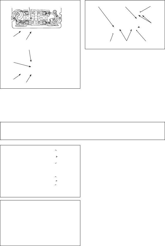
1ø 100V-120V |
White |
220V-240V |
Green/
Yellow Black
3ø 200V-240V White
Black
Green/
Yellow Red
3)Securely fix the terminals of the AC input cord by tightening the screws at the specified locations.
4)Close the power switch cover. Tighten screw 1 on the side face of the power switch cover.
Pedal sensor cable |
AC cable |
Power switch |
Staples
 (large)
Pedal sensor Staples (small) |
Cable draw-out |
|
hole |
5)Firstly attach the staple supplied with the unit as accessories to the cable. Then, hammer them into the sewing machine table.
At this time, attach the staples at the locations shown in the figure.
WARNING :
1. Be sure to attach the ground wire (green/yellow) to the specified location (on the ground side).
2. Take care not to allow terminals to come in contact with each other.
3. When closing the power switch cover, take care not to allow the cord to be caught under it.
3ø 200V-240V |
Black |
|
|
|
|
|
Ac 200V-240V |
||
|
Red |
|
||
|
|
|||
|
|
|||
|
White |
|
|
|
|
|
|
||
|
Green / Yellow |
|||
1ø 100V-120V |
(ground wire) |
|||
Black |
|
|
|
|
220V-240V |
|
|
AC 100V-120V |
|
|
|
|||
|
White |
|
|
AC 220V-240V |
|
|
|
||
Green / Yellow (ground wire)
3
6)Connect the power cord to the power plug.
As shown in the figure, connect the white and black
(and red) wires to the power supply side and the green/yellow one to the grounding side.
(Caution) 1. Be sure to prepare the power plug 3 which conforms to the safety standard.
2.Be sure to connect the ground lead (green/yellow) to the grounding side.
7)Check that the power switch is in the OFF state. Then, insert the power plug coming from the power switch into the plug receptacle.
(Caution) In prior to the connection of the power plug, re-check the supply voltage specification indicated on the power box.
––
4. Attaching the connecting rod
WARNING :
To protect against possible personal injury due to abrupt start of the machine, be sure to start the following work after turning the power off and a lapse of 5 minutes or more.
5
|
4 |
|
2 |
|
|
3 |
|
|
|
|
|
1) Fix connecting rod 1 to installing hole B of |
|
|
|
3) The pressure increases as you turn reverse de- |
|
pedal lever 2 with nut 3. |
|
pressing regulator screw 4 in, and decreases as |
2) Installing connecting rod 1 to installing hole A |
|
you turn the screw out. |
will lengthen the pedal depressing stroke, and |
(Caution) 1. If the screw is excessively loosened, |
|
the pedal operation at a medium speed will be |
|
the spring will come off. |
easier. |
|
Loosen the screw to such an extent |
|
|
that the top of the screw can be ob- |
|
|
served from the case. |
|
|
2. Whenever you have adjusted the |
|
|
screw, be sure to secure the screw by |
|
|
tightening metal nut 5 to prevent the |
|
|
screw from loosening. |
––
5. Winding the bobbin thread
8
B3
1
A
2
C
4
6
7
D
6
5
E
6
1)Insert the bobbin deep into the bobbin winder spindle 1 until it will go no further.
2)Pass the bobbin thread pulled out from the spool rested on the right side of the thread stand following the order as shown in the figure on the left. Then, wind clockwise the end of the bobbin thread on the bobbin several times.
(In case of the aluminum bobbin, after winding clockwise the end of the bobbin thread, wind counterclockwise the thread coming from the bobbin thread tension several times to wind the bobbin thread with ease.)
3)Press the bobbin winder trip latch 2 in the direction of A and start the sewing machine. The bobbin rotates in the direction of C and the bobbin thread is wound up. The bobbin winder spindle 1 automatically as soon as the winding is finished.
4)Remove the bobbin and cut the bobbin thread with the thread cut retainer 3.
5)When adjusting the winding amount of the bob-
bin thread, loosen setscrew 4 and move bobbin winding lever 2 to the direction of A or B. Then tighten setscrew 4.
To the direction of A : Decrease To the direction of B : Increase
6)In case that the bobbin thread is not wound evenly on the bobbin, remove the handwheel, loosen screw 5 and adjust the height of bobbin thread tension 8.
•It is the standard that the center of the bobbin is as high as the center of thread tension disk 6.
•Adjust the position of thread tension disk 6 to the direction of D when the winding amount of the bobbin thread on the lower part of the bobbin is excessive and to the direction E when the winding amount of the bobbin thread on the upper part of the bobbin is excessive.
After the adjustment, tighten screw 5.
7)To adjust the tension of the bobbin winder, turn the thread tension nut 7.
(Caution)
1.When winding the bobbin thread, start the winding in the state that the thread between the bobbin and thread tension disk 6 is tense.
2.When winding the bobbin thread in the state that sewing is not performed, remove the needle thread from the thread path of thread take-up and remove the bobbin from the hook.
3.There is the possibility that the thread pulled out from the thread stand is loosened due to the influence (direction) of the wind and may be entangled in the handwheel. Be careful of the direction of the wind.
––
6. Adjusting the height of the knee lifter
WARNING :
Be sure to turn the power OFF before the following work in order to prevent personal injury due to unintentional starting of the sewing machine.
1
2
3
1)The standard height of the presser foot lifted using the knee lifter is 10 mm.
2)You can adjust the presser foot lift up to 13 mm using knee lifter adjust screw 1.
3)When you have adjusted the presser foot lift to over 10 mm, be sure that the bottom end of needle bar 2 in its lowest position does not hit presser foot 3.
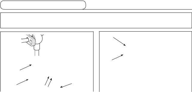
7.Installing the thread stand
1)Assemble the thread stand unit, and insert it in the hole in the machine table.
2)Tighten nut 1.
2 |
3) For ceiling wiring, pass the power cord through |
|
|
|
spool rest rod 2. |
 1
1
––

8. Lubrication
WARNING :
1. Do not connect the power plug until the lubrication has been completed so as to prevent accidents due to abrupt start of the sewing machine,
2. To prevent the occurrence of an inflammation or rash, immediately wash the related portions if oil adheres to your eyes or other parts of your body.
3. If oil is mistakenly swallowed, diarrhea or vomitting may occur. Put oil in a place where children cannot reach.
|
|
1) |
Before starting the sewing machine, fill oil pan |
|
|
||
A |
|
|
1 with JUKI MACHINE OIL #7 up to HIGH mark |
|
|
|
|
|
|
2) |
A. |
|
|
When the oil level lowers below LOW mark B, |
|
|
|
|
refill the oil pan with the specified oil. |
|
|
3) |
When you operate the machine after lubrica- |
|
B |
|
tion, you will see splashing oil through oil sight |
1 |
2 |
|
window 2 if the lubrication is adequate. |
|
|
4) |
Note that the amount of the splashing oil is un- |
|
|
|
related to the amount of the lubricating oil. |
|
|
|
|
1.When you use a new sewing machine or a sewing machine after an extended period of disuse, use the sewing machine after performing break-in at 2,000 sti/min or less.
2.For the oil for hook lubrication, purchase JUKI NEW DEFRIX OIL No. 1 (Part No. : MDFRX1600C0) or JUKI MACHINE OIL #7 (Part No. : MML007600CA).
3.Be sure to lubricate clean oil.
9.Adjusting the amount of oil (oil splashes)
WARNING :
Be extremely careful about the operation of the machine since the amount of oil has to be checked by turning the hook at a high speed.
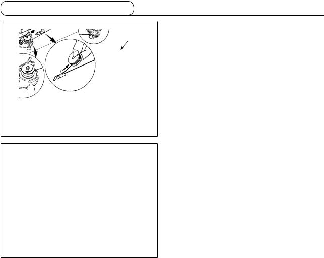
(1) Confirmation of the amount of oil in the hook
1 Amount of oil (oil splashes) confirmation paper |
2 Position to confirm the amount of oil (oil splashes) |
|
mm |
-10 mm |
|
25 |
3 |
|
Oil splashes confirmation |
against the wall |
|
|
|
surface of the bed. |
* When carrying out the procedure described below in 2, remove the slide plate and take extreme caution not to allow your fingers to come in contact with the hook.
1) If the machine has not been sufficiently warmed up for operation, make the machine run idle for approximately three minutes. (Moderate intermittent operation)
2) Place the amount of oil (oil spots) confirmation paper under the hook immediately after the machine stops running.
3) Confirm the height of the oil surface in the oil reservoir is within the range between “HIGH” and “LOW”. 4) Confirmation of the amount of oil should be completed in five seconds. (Check the period of time with a
watch.)
––

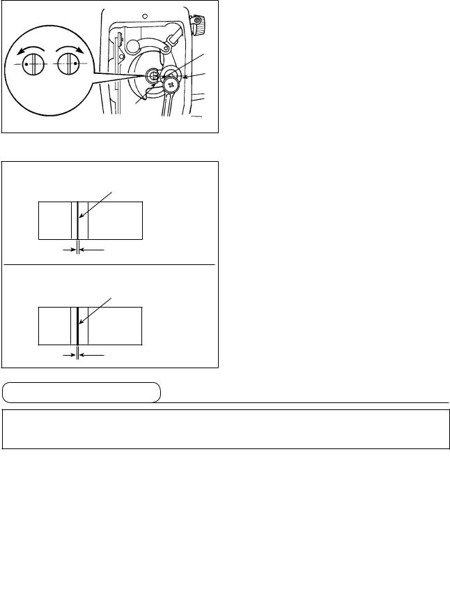
(2)Adjusting the amount of oil (oil spots) in the hook
1)Turning the oil amount adjustment screw attached on the hook driving shaft front bushing in the “+” direction (in direction A) will increase the amount of oil (oil spots) in the hook, or in the “–” direction (in
|
B |
direction B) will decrease it. |
|
2) After the amount of oil in the hook has been prop- |
|
A |
|
|
|
erly adjusted with the oil amount adjustment screw, |
|
|
|
|
|
|
make the sewing machine run idle for approximately |
|
|
|
|
|
30 seconds to check the amount of oil in the hook. |
(3) Sample showing the appropriate amount of oil in the hook
Appropriate amount of oil (small)
Splashes of oil from the hook
|
|
|
|
|
|
|
|
|
|
|
|
|
|
|
|
|
|
|
|
* mm |
|
|
|
|
|
|
|
|
|
DDL-8700AS-7 |
|
|
|
|
|
|
|
* mm |
1mm |
|
|||
|
|
|
|
|
|
DDL-8700AH-7 |
|
|||
|
|
|
|
|
|
|
|
|
|
|
|
|
|
|
|
|
|
|
|
|
|
|
|
|
|
|
|
|
|
|
|
|
Appropriate amount of oil (large)
Splashes of oil from the hook
* mm * mm DDL-8700AS-7 2mm DDL-8700AH-7 3mm
1)The amount of oil shown in the samples on the left should be finely adjusted in accordance with sewing processes.
Be careful not to excessively increase/decrease the amount of oil in the hook. (If the amount of oil is too small, the hook will be seized (the hook will be hot). If the amount of oil is too much, the sewing product may be stained with oil.)
2)Adjust the amount of oil in the hook so that the oil amount (oil splashes) should not change while checking the oil amount three times (on the three sheets of paper).
(4) Confirmation of the amount of oil supplied to the face plate parts
1 Amount of oil (oil splashes) confirmation paper
25 mm
2 Position to confirm the amount of oil
(oil splashes)
Oil splashes  confirmation paper
*When carrying out the work described below in 2), remove the face plate and take extreme caution not to allow your fingers to come in contact with the thread take-up lever.
1)If the machine has not been sufficiently warmed up for operation, make the machine run idle for approximately three minutes. (Moderate intermittent operation)
2)Place the amount of oil (oil spots) confirmation paper under the hook immediately after the machine stops running.
3)Confirm the height of the oil surface in the oil reservoir is within the range between “HIGH” and “LOW”.
4)The time required for the confirmation of the amount of oil (oil splashes) should be completed in ten seconds. (Measure the period of time with a watch.)
– 10 –
(5)Adjusting the amount of oil supplied to the face plate parts
1)Adjust the amount of oil supplied to the thread
take-up and needle bar crank 2 by turning adjust pin 1.
C |
B |
|
2) The minimum amount of oil is reached when |
|
|
A |
marker dot A is brought close to needle bar |
|
|
|
|
|
1 |
2 |
crank 2 by turning the adjust pin in direction B. |
|
|
3) The maximum amount of oil is reached when |
|
maximum minimum |
|
||
|
|
|
marker dot A is brought to the position just op- |
|
|
1 |
posite from the needle bar crank by turning the |
|
|
|
|
|
|
|
adjust pin in direction C. |
(6) Sample showing the appropriate amount of oil supplied to the face plate parts
Appropriate amount of oil (small)
Splashes of oil from the thread take-up lever
1 mm
Appropriate amount of oil (large)
Splashes of oil from the thread take-up lever
2 mm
1)The state given in the figure shows the appropriate amount of oil (oil splashes). It is necessary to finely adjust the amount of oil in accordance with the sewing processes. However, do not excessively increase/decrease the amount of oil in the hook. (If the amount of oil is too small, the hook will be seized (the hook will be hot). If the amount of oil is too much, the sewing product may be stained with oil.)
2)Adjust the amount of oil in the hook so that the oil amount (oil splashes) should not change while checking the oil amount three times (on the three sheets of paper).
10. Attaching the needle
WARNING :
Be sure to turn the power OFF before the following work in order to prevent personal injury due to unintentional starting of the sewing machine.
|
|
|
|
Use the specified needle for the machine. Use the |
|
|
|
|
|
||
|
|
|
|
proper needle in accordance with the thickness of |
|
|
D |
B |
|
thread used and the kinds of the materials. |
|
|
|
|
|
1) |
Turn the handwheel until the needle bar reaches |
|
|
|
A |
|
the highest point of its stroke. |
|
C |
|
2) |
Loosen screw 2, and hold needle 1 with its |
|
1 |
|
|
|||
|
|
|
|
indented part A facing exactly to the right in |
|
|
|
|
|
|
|
|
2 |
|
|
3) |
direction B. |
|
|
|
|
Insert the needle fully into the hole in the needle |
|
|
|
|
|
|
bar in the direction of the arrow until the end of |
|
|
|
|
|
hole is reached. |
|
|
|
|
4) |
Securely tighten screw 2. |
|
|
|
|
||
5)Check that long groove C of the needle is facing exactly to the left in direction D.
(Caution) When polyester filament thread is used, if the indented part of the needle is tilted toward operator's side, the loop of thread becomes unstable. As a result, hangnail of thread or thread breakage may occur. For the thread that such phenomenon is likely to occur, it is effective to attach the needle with its indented part slightly slanting on the rear side.
– 11 –

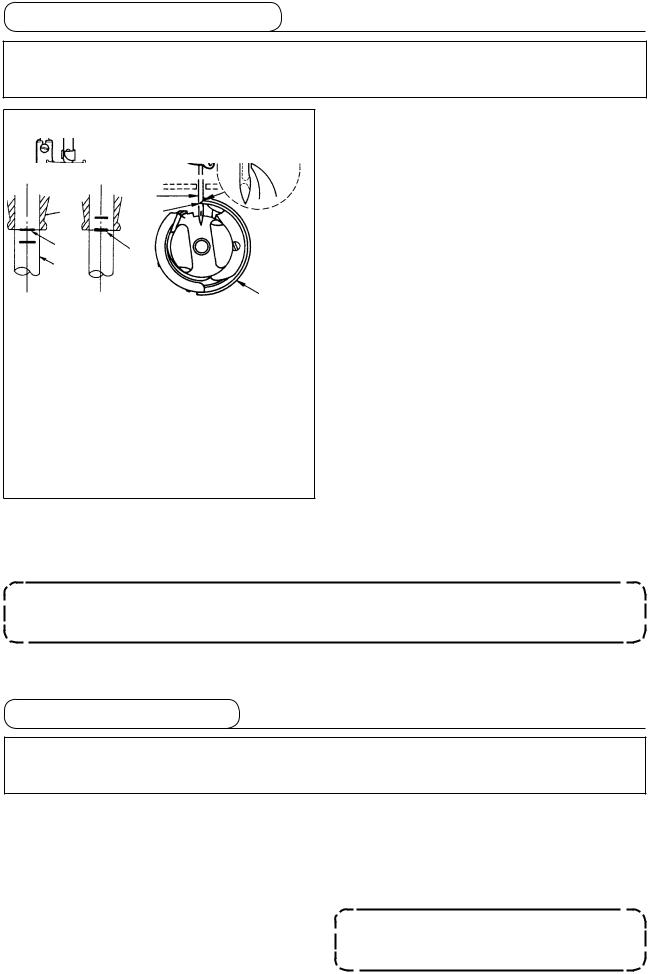
11.Setting the bobbin into the bobbin case
1)Pass the thread through thread slit A, and
A |
pull the thread in direction C. By so doing, the |
|
|
|
thread will pass under the tension spring and |
|
come out from notch B. |
|
2) Check that the bobbin rotates in the direction of |
|
the arrow when thread is pulled. |
B
C
12. Adjusting the stitch length
* The dial calibration is in millimeters.
1) Turn stitch length dial 1 in the direction of the arrow, and align the desired number to marker dot A on the machine arm.
1 |
A |
|
13. Presser foot pressure
B A
1
29 to 32 mm
2
1)Loosen nut 2. As you turn presser spring regulator 1 clockwise (in direction A), the presser foot pressure will be increased.
2)As you turn the presser spring regulator counterclockwise (in direction B), the pressure will be decreased.
3)After adjustment, tighten nut 2.
The standard value of the pressure regulating thumb screw is 29 to 32 mm.
14. Hand lifter
1) The presser foot is lifted by moving the lever upward.
2) The presser foot is lowered by moving the lever downward.
– 12 –

15. Adjusting the height of the presser bar
WARNING :
Be sure to turn the power OFF before the following work in order to prevent personal injury due to unintentional starting of the sewing machine.
1) Loosen setscrew 1, and adjust the presser bar height or the angle of the presser foot.
2) After adjustment, securely tighten the setscrew
11.
16.Threading the machine head
WARNING :
Be sure to turn the power OFF before the following work in order to prevent personal injury due to unintentional starting of the sewing machine.
– 13 –

17. Thread tension
1
B |
A |
E F |
|
||
|
|
|
|
|
3 |
|
2 |
|
C
D
(1) Adjusting the needle thread tension
1)The length of thread remaining at the needle tip after thread trimming is shortened by turning tension regulating nut No. 1 1 clockwise in direction A.
2)It is lengthened by turning the nut counterclockwise in direction B.
3)The needle thread tension is increased by turning tension regulating nut No. 2 2 clockwise in direction C.
4)It is decreased by turning the nut counterclockwise in direction D.
(2) Adjusting the bobbin thread tension
1)The bobbin thread tension is increased by turning tension regulating screw 3 clockwise in direction E.
2)It is decreased by turning the screw counterclockwise in direction F.
18. Thread take-up spring
5 4
1
2
A
B
31
(1) Changing the stroke of thread take-up spring 1
1)Loosen setscrew 2.
2)As you turn tension post 3 clockwise (in direction A), the stroke of the thread take-up spring will be increased.
3)As you turn the knob counterclockwise (in direction B), the stroke will be decreased.
(2) Changing the pressure of thread take-up spring 1
1)Loosen setscrew 2, and remove tension post 3.
2)Loosen setscrew 4.
3)As you turn tension post 3 clockwise (in direction A), the pressure will be increased.
4)As you turn the tension post counterclockwise (in direction B), the pressure will be decreased.
19. Adjusting the thread take-up stroke
WARNING :
Be sure to turn the power OFF before the following work in order to prevent personal injury due to unintentional starting of the sewing machine.
|
|
1) |
When sewing heavy-weight materials, move |
|
|
||
A B |
|
|
thread guide 1 to the left (in direction A) to |
1 |
|
|
increase the length of thread pulled out by the |
|
|
thread take-up. |
|
|
|
|
|
C |
|
2) |
When sewing light-weight materials, move |
|
|
|
thread guide 1 to the right (in direction B) to |
|
|
|
decrease the length of thread pulled out by the |
|
|
|
thread take-up. |
|
|
3) |
Normally, thread guide 1 is positioned in a way |
|
|
|
that marker line C is aligned with the center of |
|
– 14 – |
the screw. |
|
|
|
||
20. Needle-to-hook relationship
WARNING :
Be sure to turn the power OFF before the following work in order to prevent personal injury due to unintentional starting of the sewing machine.
|
C |
1 |
D |
|
A |
|
B |
|
0.04 to 0.1 mm |
4 |
|
3 |
5 |
A |
B |
|
|
2 |
|
|
a |
(1) Adjust the timing between the needle and the hook as follows :
1)Turn the handwheel to bright the needle bar down to the lowest point of its stroke, and loosen setscrew 1.
(Adjusting the needle bar height)
2)(For a DB needle) Align marker line A on needle bar 2 with the bottom end of needle bar
lower bushing 3, then tighten setscrew 1. (For a DA needle) Align marker line C on needle bar 2 with the bottom end of needle bar lower bushing 3, then tighten setscrew 1.
(Adjusting position of the hook a)
3)(For a DB needle) Loosen the three hook setscrews, turn the handwheel and align marker
line B on ascending needle bar 2 with the bot-
tom end of needle bar lower bushing 3. (For a DA needle) Loosen the three hook
setscrews, turn the handwheel and align marker
line D on ascending needle bar 2 with the bottom end of needle bar lower bushing 3.
4)After making the adjustments mentioned in the above steps, align hook blade point 5 with the center of needle 4. Provide a clearance of 0.04 mm to 0.1 mm (DDL-8700AH-7 : 0.06 to 0.17mm) (reference value) between the needle and the hook, then securely tighten setscrews in the hook.
If the clearance between the blade point of hook and the needle is smaller than the specified value, the blade point of hook will be damaged. If the clearance is larger, stitch skipping will result.
21. Height of the feed dog
WARNING :
Be sure to turn the power OFF before the following work in order to prevent personal injury due to unintentional starting of the sewing machine.
|
|
To adjust the height of the feed dog : |
|
1 |
|
||
|
1 |
Loosen screw 2 of crank 1. |
|
|
|
||
|
|
2 |
Move the feed bar up or down to make adjust- |
|
0.75 to 0.85 mm |
|
ment. |
|
3 |
Securely tighten screw 2. |
|
2 |
DDL-8700AS-7 |
|
If the clamping pressure is insufficient, |
|
1.15 to 1.25 mm |
|
|
|
|
the motion of the forked portion be- |
|
|
DDL-8700AH-7 |
|
comes heavy. |
|
|
|
|
– 15 –
Loading...