


DDL-900B
Table of contents
 Loading...
DDL-900B
INSTRUCTION MANUAL

CONTENTS
I. SPECIFICATIONS ........................................................................................ 1
II. SET-UP ........................................................................................................ 3
1. Installation ......................................................................................................................................... 3
2. Installing the pedal sensor ...............................................................................................................4
3. Installing the power switch (for CE) ................................................................................................ 4
4. Connecting the connector ...............................................................................................................5
5. How to install the power plug .......................................................................................................... 6
6. Attaching the connecting rod ..........................................................................................................6
7. Winding the bobbin thread ..............................................................................................................7
8. Adjusting the height of the knee lifter ............................................................................................. 8
9. Installing the thread stand ...............................................................................................................8
10. Lubrication ........................................................................................................................................9
11. Adjusting the amount of oil (oil splashes) .................................................................................... 10
12. Attaching the needle .......................................................................................................................12
13. Setting the bobbin into the bobbin case ......................................................................................13
14. Adjusting the stitch length .............................................................................................................13
15. Presser foot pressure ..................................................................................................................... 13
16. Hand lifter ........................................................................................................................................13
17. Adjusting the height of the presser bar ........................................................................................ 14
18. Threading the machine head .........................................................................................................14
19. Thread tension ................................................................................................................................15
20. Thread take-up spring ....................................................................................................................15
21. Adjusting the thread take-up stroke .............................................................................................15
22. Needle-to-hook relationship ..........................................................................................................16
23. Height of the feed dog .................................................................................................................... 16
24. Tilt of the feed dog .......................................................................................................................... 17
25. Adjusting the feed timing ...............................................................................................................17
26. Counter knife ................................................................................................................................... 18
27. Pedal pressure and pedal stroke ...................................................................................................18
28. Adjustment of the pedal .................................................................................................................19
29. Marker dots on the handwheel ......................................................................................................19
III. FOR THE OPERATOR ............................................................................. 20
1. Operating procedure of the sewing machine ............................................................................... 20
2. Setting procedure of the machine head .......................................................................................21
3. Operation panel built in the machine head ..................................................................................22
4. Operating procedure of the sewing pattern .................................................................................23
5. One-touch setting ...........................................................................................................................25
6. Setting of functions ........................................................................................................................26
7. Production support function .........................................................................................................27
8. Setting of thread clamp (NB type only) .........................................................................................29
9. Function setting list ........................................................................................................................ 31
10. Detailed explanation of selection of functions ............................................................................35
11. Automatic compensation of neutral point of the pedal sensor .................................................. 45
12. Selection of the pedal specications ............................................................................................ 46
13. Setting of the auto lifter function ..................................................................................................46
14. Selecting procedure of the key-lock function .............................................................................. 47
15. Initialization of the setting data .....................................................................................................47
16. LED hand light .................................................................................................................................48
17. Height adjustable one-touch type reverse stitching switch ....................................................... 48
IV. MAINTENANCE ....................................................................................... 49
1. Adjusting the machine head ..........................................................................................................49
2. Error codes ...................................................................................................................................... 50
i

I. SPECIFICATIONS
Supply voltage Single phase 220V/230V/240V
Frequency 50Hz/60Hz
Operating environment
Input 210VA
Temperature : 5 to 35˚C
Humidity 35 - 85 %
DDL-900B-
S : Light- to Medium-weight materials
H : Heavy-weight materials
DDL-900B-S DDL-900B-H
Application
Max. sewing speed 5,000 sti/min 4,000 sti/min
Thread trimming speed 210 sti/min 210 sti/min
Stitch length 4 mm 5 mm
Presser foot lift (by knee lifter) 13 mm 13 mm
Needle
Lubricating oil JUKI CORPORATION GENUINE OIL 7
Noise
*1
Light- to Medium-weight materials Heavy-weight materials
DB × 1 (#14) #9 to 18, 134 (Nm 90) Nm
65 to 110 (for CE)
- Equivalent continuous emission
sound pressure level (LpA) at the
workstation :
A-weighted value of 81.0 dB; (Includes
KpA = 2.5 dB); according to ISO
10821- C.6.2 -ISO 11204 GR2 at
4,000 sti/min.
A-weighted value of 80.0 dB; (Includes
KpA = 2.5 dB); according to ISO
10821- C.6.2 -ISO 11204 GR2 at
3,500 sti/min.
- Equivalent continuous emission
sound pressure level (LpA) at the
workstation :
A-weighted value of 83.0 dB; (Includes
KpA = 2.5 dB); according to ISO
10821- C.6.2 -ISO 11204 GR2 at
4,000 sti/min.
A-weighted value of 80.0 dB; (Includes
KpA = 2.5 dB); according to ISO
10821- C.6.2 -ISO 11204 GR2 at
3,500 sti/min.
DB x 1 (#21) #20 to 23
• The sewing speed preset at the time of shipping : 4,000 sti/min
*1 : Needle used depends on the destination.
– 1 –
C
H
G
E
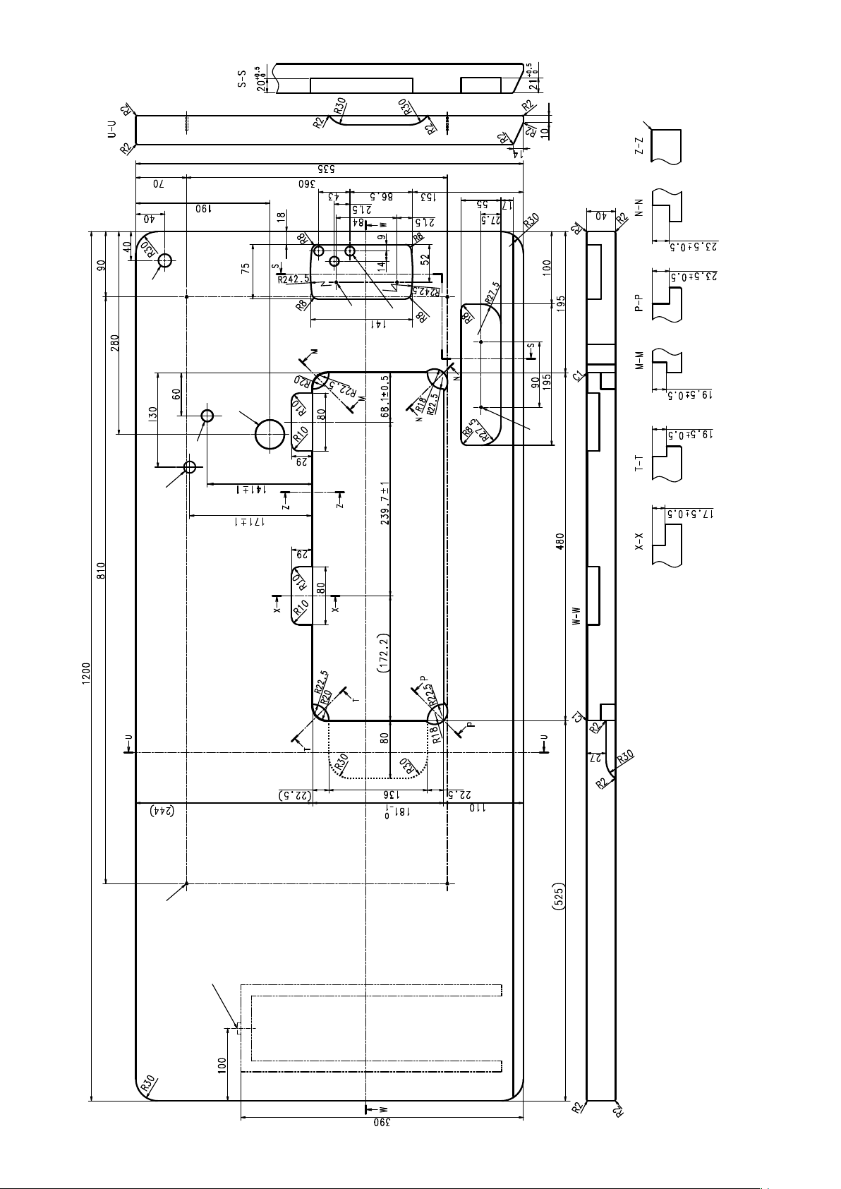
DRAWING OF TABLE
J
D
F
I
A
B
– 2 –
drilled hole
4xø3.4 on the bottom surface, depth 20 (Drill a hole at the time of set-up.)
Installing position of drawer stopper (on the reverse side)
ø18 drilled hole
3xø13 drilled hole
2xø3.5, depth 10
2xø3.5, depth 10
ø40±0.5
ø16 depth 30
ø16 depth 30 (for optional parts)
A
B
C
D
E
F
C1.5 to C2.5 (hinge side only)
G
H
I
J

II. SET-UP
1. Installation
D
1) Carry the sewing machine with two persons as
shown in the gure above.
Do not hold the handwheel D.
C
❸
❶
❷
❽
❶
A B
❹
❾
❸
❶
19.5 mm23.5 mm
❸
2) Do not put protruding articles such as the screw-
driver and the like at the location where the
sewing machine is placed.
3) Adjust so that the underside cover is supported at
the four corners of the table. Mount rubber hinge
seat ❽ on the table and x it on the table with a
nail.
4) Two rubber seats ❶ for supporting the head por-
tion on the operator side A are xed on the extended portion of the table by hitting the nail ❷ ,
and the other two rubber cushion seats ❸ on the
hinge side B are xed by using a rubber-based
adhesive. Then, underside cover ❹ is placed.
❼
5) Fit hinge ❼ into the opening in the machine bed,
and t the machine head to table rubber hinge ❽
before placing the machine head on cushions ❾
on the four corners.
6) Securely t machine head support stand ❻ in
the hole (60 x 141 x ø16, depth 30) (refer to H in
DRAWING OF TABLE p. 2) in the table.
❽
❻
1. Be sure to install the machine head support rod ❻ supplied with the unit.
2. If a pair of scissors or the like is caught between the control box and the table, the control box
cover can break. To prevent such an accident, do not place anything on C section.
3. Be aware that the control box breakage and/or oil leakage can occur if operating the sewing
machine with the machine head support rod ❻ removed.
❼
– 3 –

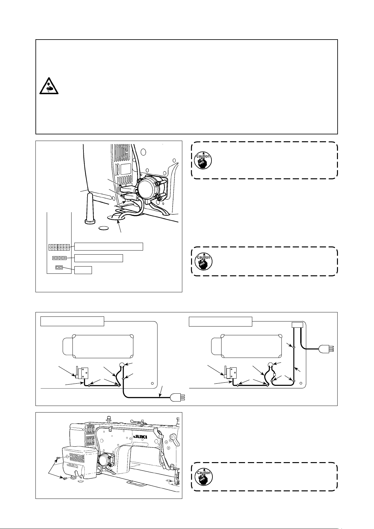
2. Installing the pedal sensor
❶
3. Installing the power switch (for CE)
WARNING :
1. Be sure to attach the ground wire (green/yellow) to the specied location (on the ground side).
2. Take care not to allow terminals to come in contact with each other.
3. When closing the power switch cover, take care not to allow the cord to be caught under it.
1) Install the pedal sensor to the table with mounting
screws ❶ supplied with the unit.
It is necessary to install the pedal sensor at such
a position that the connecting rod is perpendicu-
lar to the table.
2) After the completion of installation of the pedal
sensor on the table, place the sewing machine
head on the table.
❷
1ø 220V-240V
❹
Blue Blue
❶
Do not insert the power plug into the plug
receptacle.
1
) Remove screw ❶ on the side face of the power
switch cover to open the power switch cover.
2) Pass AC input cord ❷(40145128),
❸(M6102461DAA) through the rear face of the
power switch. Bundle the cord with cable clip
band ❹ to secure it.
3) Securely x the terminals of the AC input cord
❷(40145128), ❸(M6102461DAA) by tightening
the screws at the specied locations.
4) Close the power switch cover. Tighten screw ❶
on the side face of the power switch cover.
❷
Green/
Yellow
Green/
Yellow
❸
Brown Brown
– 4 –
4. Connecting the connector
WARNING :
• To protect against personal injury resulting from abrupt start of the sewing machine, be sure to
turn the power OFF, unplug the machine and wait for ve minutes or more before installing the
pedal sensor.
• To prevent damage of device caused by maloperation and wrong specications, be sure to connect
all the corresponding connectors to the specied places. (If any of the connectors is inserted into
a wrong connector, not only the device corresponding to the connector can break but also it can
start abruptly, inviting the risk of personal injury.)
• To prevent personal injury caused by maloperation, be sure to lock the connector with lock.
• Do not connect the power plug until the connection of cords is completed.
• Fix the cords while taking care not to forcibly bend them or excessively clamp them with staples.
• As for the details of handling respective devices, read carefully the Instruction Manuals supplied
with the devices before handling the devices.
❸
❷
❶
❹
Machine head connector
AC power supply
Pedal
Connector connection diagram
Do not insert the power plug into the wall
outlet.
Check to be sure that the power switch is
turned OFF.
1) Connect the connectors listed below to the con-
trol box in the order of ❶ to ❸.
❶ Pedal sensor cable
❷ AC input cable
❸ Machine head connector
For the connection ports of the cables, refer to
the connector layout drawing.
Be sure to fully insert the connectors into
the corresponding ports until they are
locked.
2) Draw out cable of the control box through cable
draw-out hole ❹ to route it to the underside of
the sewing machine table.
Underside of the table
Pedal sensor
❶
❻
Slack
❺
❹
❺
❷
Underside of the table
❺
Pedal sensor
❶
Slack
❺
(For CE)
❹
❺
❷
3) Fix pedal sensor cable ❶ and AC input cable ❷
with a staple ❺.
4) Attach the solenoid cover with two solenoid cover
setscrews ❻ which are supplied with the unit as
accessories.
Take care not to allow the cords to be
caught under the cover when attaching
the cover.
– 5 –
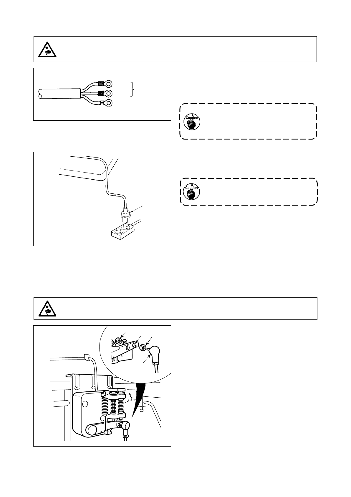
5. How to install the power plug
WARNING :
1. Be sure to attach the ground wire (green/yellow) to the specied location (on the ground side).
2. Take care not to allow terminals to come in contact with each other.
1ø 220-240V
Blue
Brown
Green / Yellow
(ground wire)
AC 220-240V
❶
1) Connect the power cord to power plug ❶. Con-
nect the blue and brown wires (1ø) to the power
supply side and the green/yellow wire to the earth
side as illustrated in the gure.
1. Be sure to prepare the power plug ❶
which conforms to the safety standard.
2. Be sure to connect the ground lead
(green/yellow) to the grounding side.
2) Check that the power switch is in the OFF state.
Then, insert the power plug ❶ coming from the
power switch into the plug receptacle.
In prior to the connection of the power
plug ❶, re-check the supply voltage spec-
ication indicated on the control box.
* The power plug ❶ is different in shape ac-
cording to the destination of the sewing
machine.
6. Attaching the connecting rod
WARNING :
To protect against possible personal injury due to abrupt start of the machine, be sure to start the
following work after turning the power off and a lapse of 5 minutes or more.
❸
❶
❷
❸
Fix connecting rod ❶ to installing hole of pedal lever
❷ with nut ❸.
– 6 –
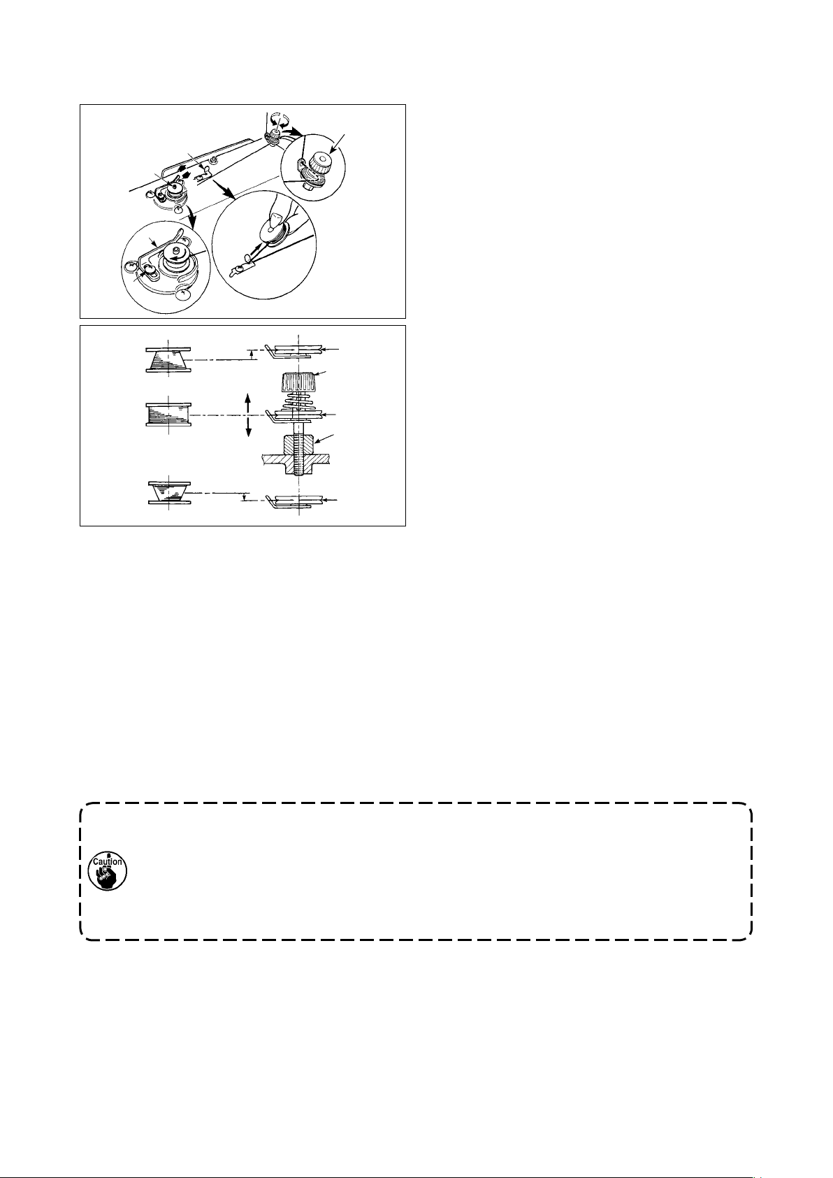
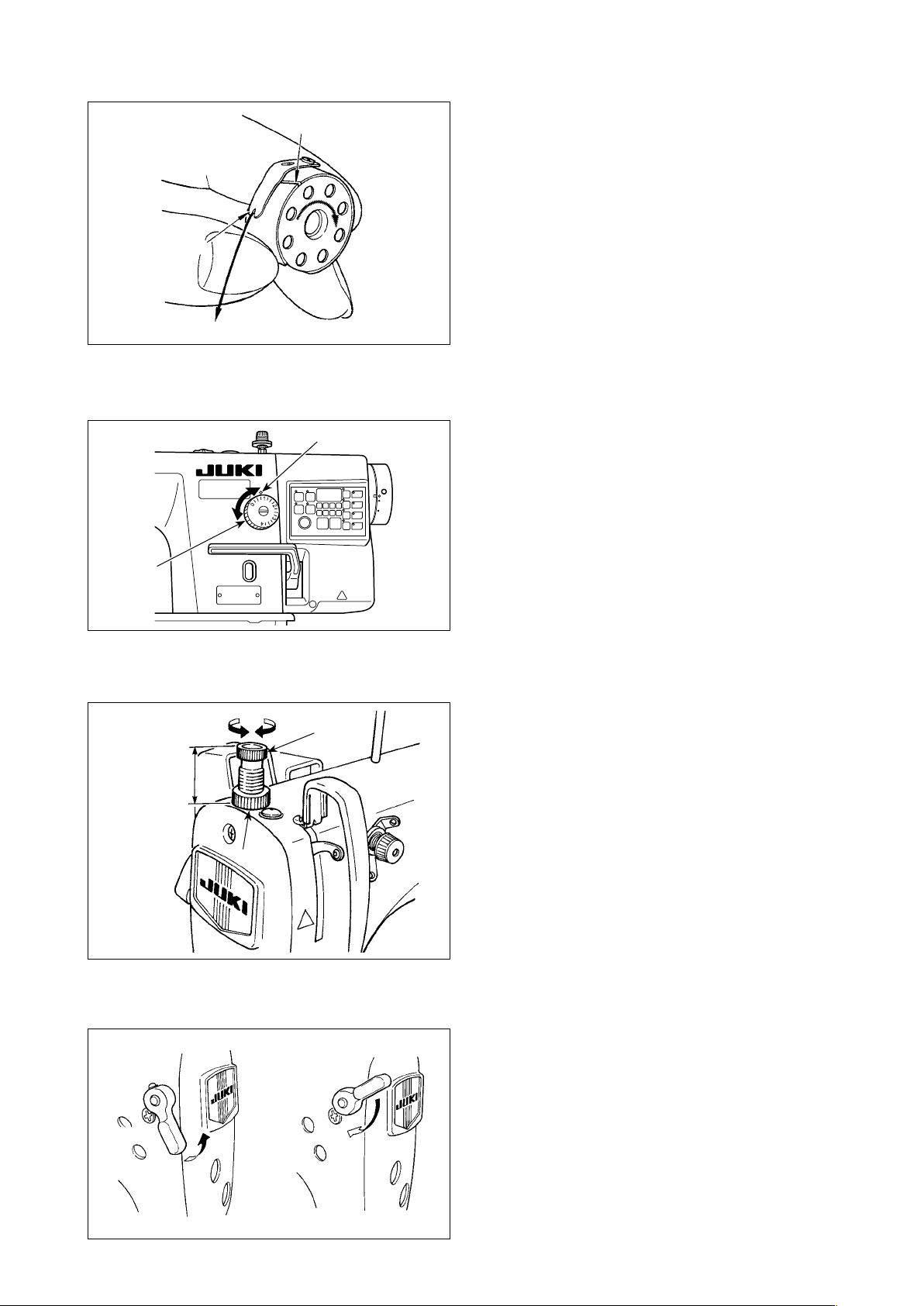
7. Winding the bobbin thread
1) Insert the bobbin deep into the bobbin winder
❽
❸
B
❶
A
❷
❹
C
❻
❼
D
❻
❺
E
❻
6) In case that the bobbin thread is not wound evenly on the bobbin, loosen screw ❺ and adjust the height
of bobbin thread tension ❽.
• It is the standard that the center of the bobbin is as high as the center of thread tension disk ❻.
• Adjust the position of thread tension disk ❻ to the direction of D when the winding amount of the bobbin
thread on the lower part of the bobbin is excessive and to the direction E when the winding amount of
the bobbin thread on the upper part of the bobbin is excessive.
After the adjustment, tighten screw ❺.
7) To adjust the tension of the bobbin winder, turn the thread tension nut ❼.
spindle ❶ until it will go no further.
2) Pass the bobbin thread pulled out from the
spool rested on the right side of the thread stand
following the order as shown in the gure on the
left. Then, wind clockwise the end of the bobbin
thread on the bobbin several times.
(In case of the aluminum bobbin, after winding
clockwise the end of the bobbin thread, wind
counterclockwise the thread coming from the
bobbin thread tension several times to wind the
bobbin thread with ease.)
3) Press the bobbin winder trip latch ❷ in the direc-
tion of A and start the sewing machine. The bob-
bin rotates in the direction of C and the bobbin
thread is wound up. The bobbin winder spindle ❶
automatically as soon as the winding is nished.
4) Remove the bobbin and cut the bobbin thread
with the thread cut retainer ❸.
5) When adjusting the winding amount of the bobbin
thread, loosen setscrew ❹ and move bobbin
winding lever ❷ to the direction of A or B. Then
tighten setscrew ❹.
To the direction of A : Decrease
To the direction of B : Increase
1. When winding the bobbin thread, start the winding in the state that the thread between the
bobbin and thread tension disk ❻ is tense.
2. When winding the bobbin thread in the state that sewing is not performed, remove the needle
thread from the thread path of thread take-up and remove the bobbin from the hook.
3. There is the possibility that the thread pulled out from the thread stand is loosened due to
the inuence (direction) of the wind and may be entangled in the handwheel. Be careful of the
direction of the wind.
– 7 –
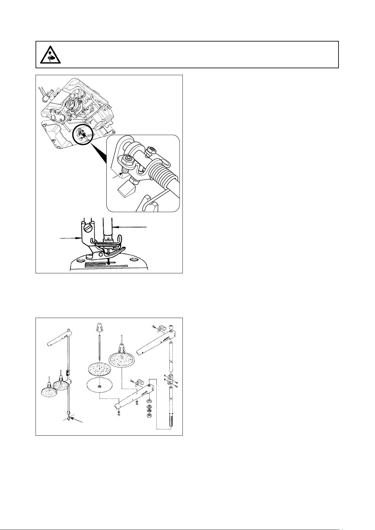
8. Adjusting the height of the knee lifter
WARNING :
Be sure to turn the power OFF before the following work in order to prevent personal injury due to
unintentional starting of the sewing machine.
❶
1) The standard height of the presser foot lifted
using the knee lifter is 10 mm.
2) You can adjust the presser foot lift up to 13 mm
using knee lifter adjust screw ❶.
3) When you have adjusted the presser foot lift
to over 10 mm, be sure that the bottom end of
needle bar ❷ in its lowest position does not hit
presser foot ❸.
❸
9. Installing the thread stand
❷
1) Assemble the thread stand unit, and insert it in
the hole in the machine table.
2) Tighten nut ❶.
❶
– 8 –
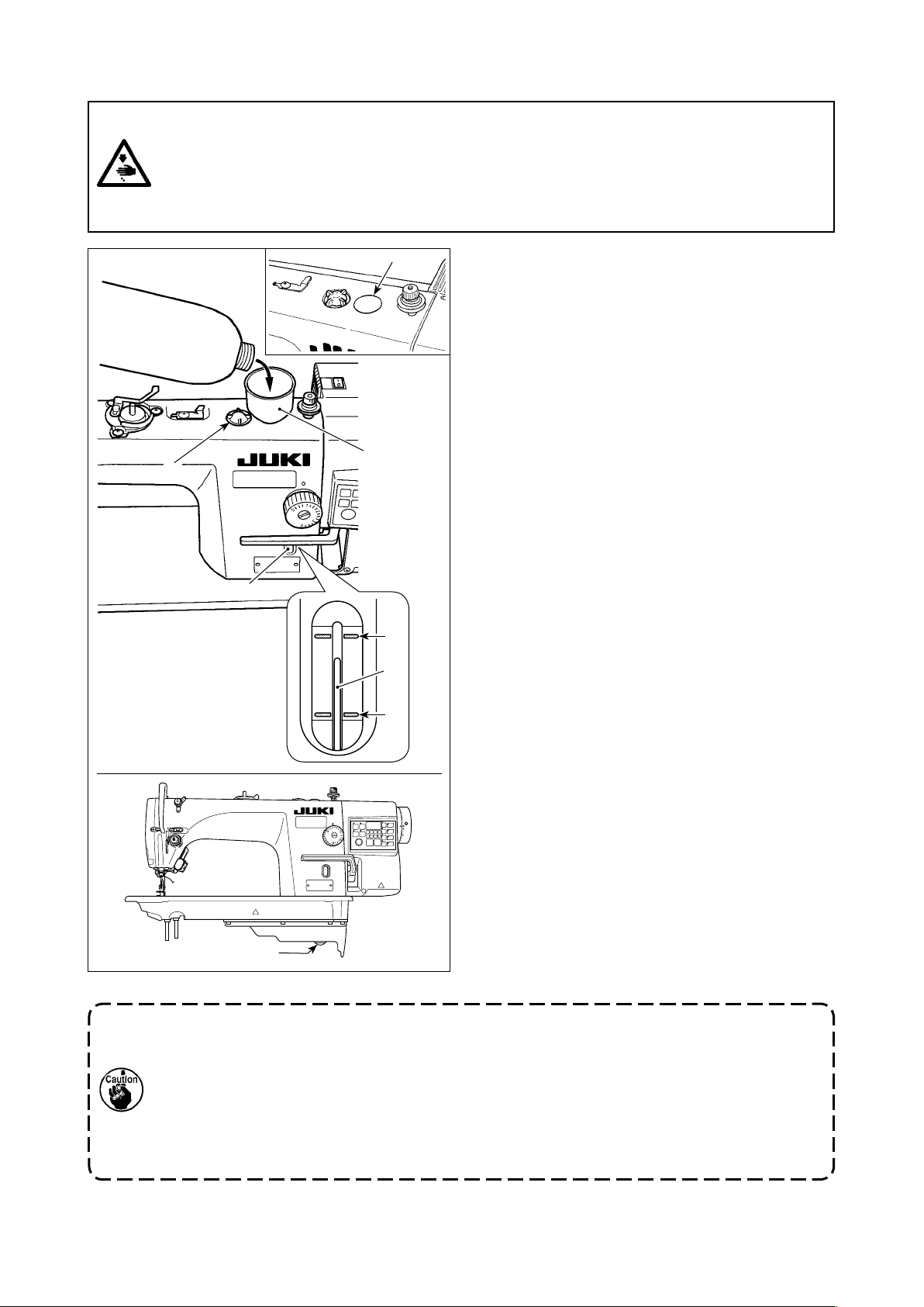
10. Lubrication
WARNING :
1. Do not connect the power plug until the lubrication has been completed so as to prevent accidents due to abrupt start of the sewing machine,
2. To prevent the occurrence of an inammation or rash, immediately wash the related portions if oil
adheres to your eyes or other parts of your body.
3. If oil is mistakenly swallowed, diarrhea or vomitting may occur. Put oil in a place where children
cannot reach.
❻
❷
❺
❹
A
❸
B
❶
1) Before running the sewing machine, remove
rubber plug ❶ from the top of the machine arm,
and add oil through the oil inlet using accessory
funnel ❹ supplied with the sewing machine.
2) Fill the oil tank with the oil until the top end of
oil amount indicating rod ❸ comes between the
upper engraved marker line A and the lower
engraved marker line B of oil amount indicating
window ❷.
If the oil is lled excessively, it will lead from the
junction between the oil shield and bed, or from
the junction between the rubber plug and bed,
or proper lubrication will not be performed. So,
be careful. In addition, when the oil is vigorously
lled, it may overow from the oil hole. So, be
careful.
* When oil is added until MAX. line A is reached,
the oil quantity becomes 600 cc.
* Check the oil quantity while the sewing ma-
chine is at rest.
* Check the quantity of oil in the oil tank by view-
ing the oil surface from the side of oil amount
indicating window ❷.
3) When you operate the sewing machine, rell oil if
the top end of oil amount indicating rod ❸ comes
down to the lower engraved marker line B of oil
amount indicating window ❷.
4) When you operate the machine after lubrication,
you will see splashing oil through oil sight window
❻ if the lubrication is adequate.
* Note that the amount of the splashing oil is
unrelated to the amount of the lubricating oil.
1. When you use a new sewing machine or a sewing machine after an extended period of disuse, use the sewing machine after performing break-in at 2,000 sti/min or less.
2. For the oil lubrication, purchase JUKI CORPORATION GENUINE OIL 7 (Part No. :
MML007600CA).
3. Be sure to lubricate clean oil.
4. Be aware oil leakage can occur if the surface of added oil quantity exceeds MAX. line A.
5. Transporting the sewing machine with the sewing machine lled with oil can give rise to the
risk of oil leakage. Be sure to discharge oil from the sewing machine through drain cock ❺.
– 9 –

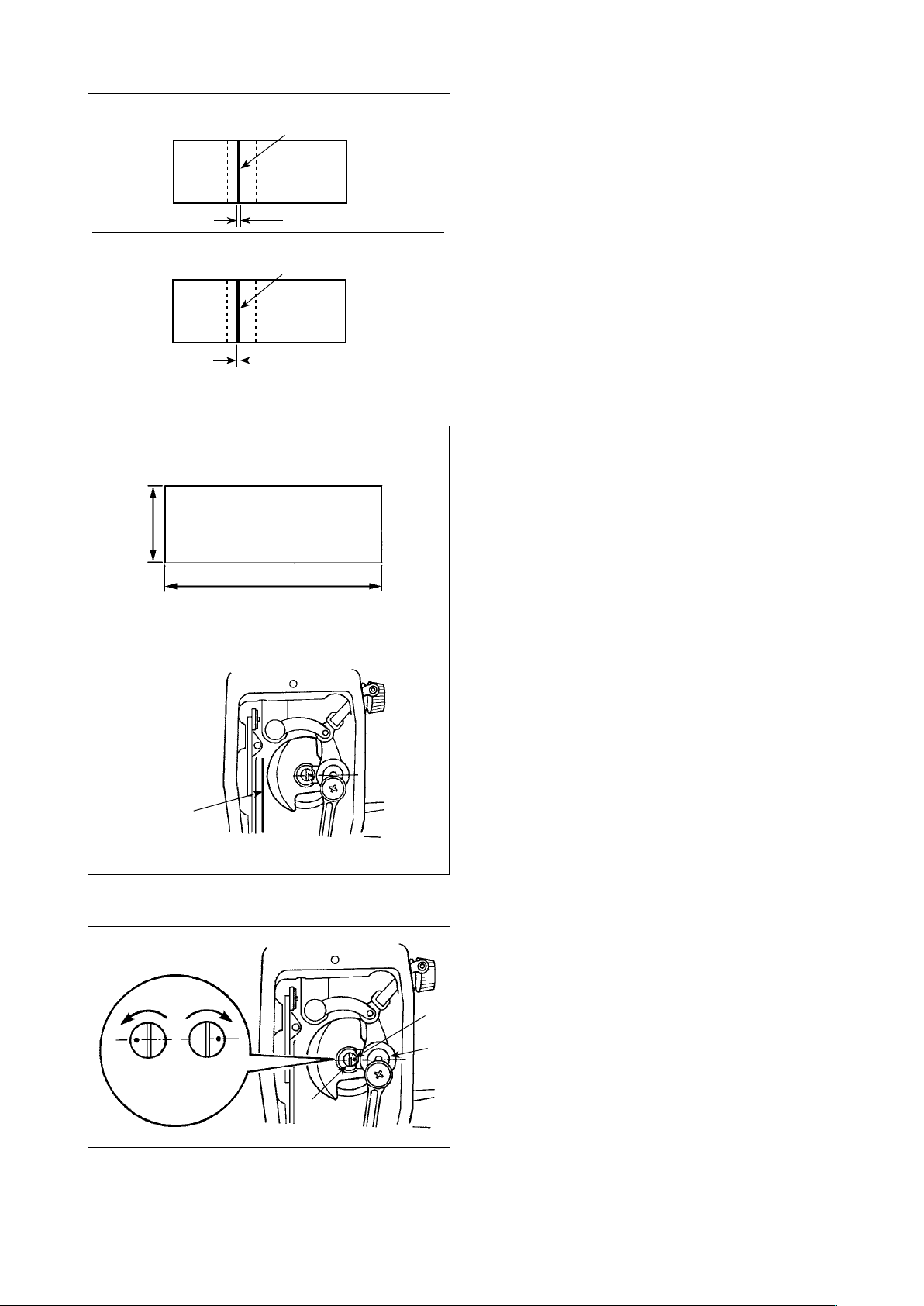
11. Adjusting the amount of oil (oil splashes)
WARNING :
Be extremely careful about the operation of the machine since the amount of oil has to be checked
by turning the hook at a high speed.
(1) Conrmation of the amount of oil in the hook
Amount of oil (oil splashes) conrmation paper
①
25 mm
70 mm
Oil splashes conrmation paper
Position to conrm the amount of oil (oil splashes)
②
3 - 10 mm
Closely t the paper against the wall
surface of the bed.
* When carrying out the procedure described below in 2), remove the slide plate and take extreme caution
not to allow your ngers to come in contact with the hook.
1) If the machine has not been sufciently warmed up for operation, make the machine run idle for approxi-
mately three minutes. (Moderate intermittent operation)
2) Place the amount of oil (oil spots) conrmation paper under the hook immediately after the machine stops
running.
3) Check to be sure that the oil surface in the oil shield rests in the range between the "MAX. line" and the
"MIN. line".
4) Conrmation of the amount of oil should be completed in ve seconds. (Check the period of time with a
watch.)
(2) Adjusting the amount of oil (oil spots) in the hook
1) Tilt the sewing machine. Turn oil amount adjust-
ment screw ❶, which is mounted on the front
bushing of lower shaft, in the "+" direction (direc-
B
A
❶
tion A) to increase the oil amount (oil spots), or
in the "-" direction (direction B) to decrease it.
* The oil-amount +/- indication mark is shown on
2) After the amount of oil in the hook has been
properly adjusted with the oil amount adjustment
screw ❶, make the sewing machine run idle for
approximately 30 seconds to check the amount
of oil in the hook.
the underside cover.
– 10 –
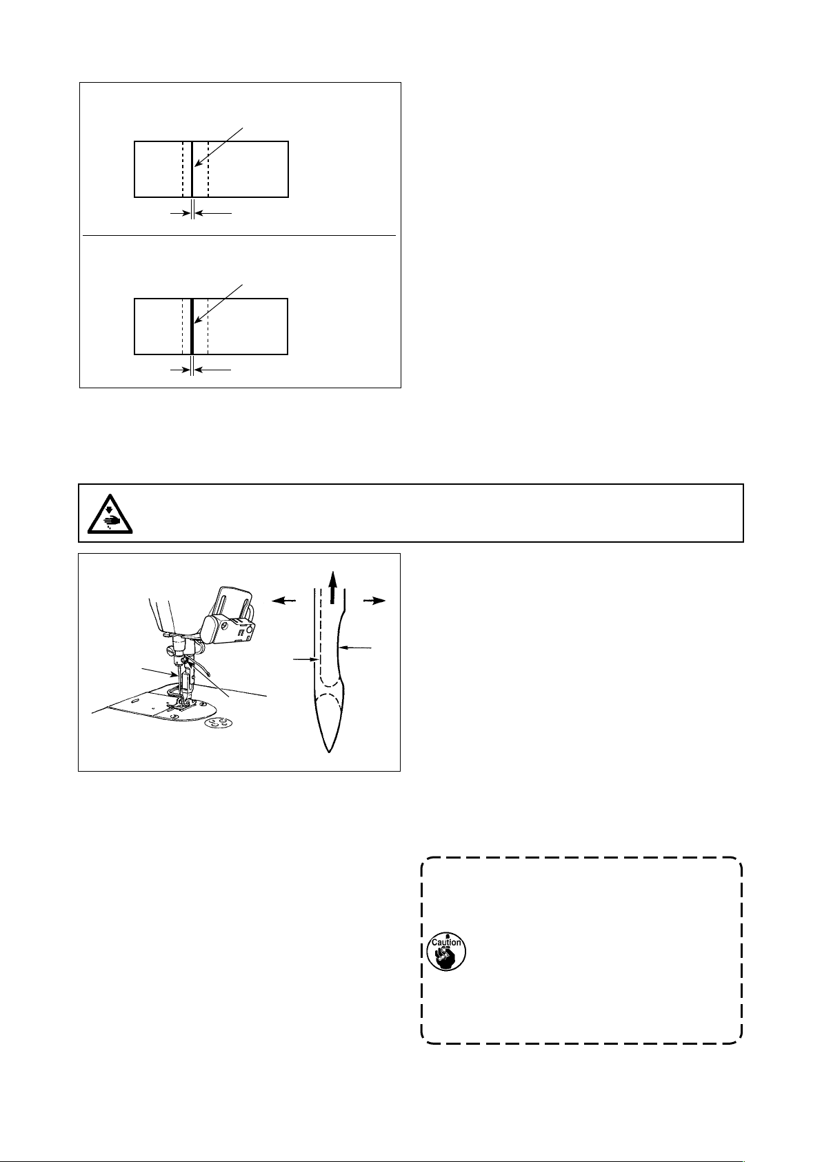
(3) Sample showing the appropriate amount of oil in the hook
Appropriate amount of oil (small)
Splashes of oil from the hook
1 mm
Appropriate amount of oil (large)
Splashes of oil from the hook
2 mm
1) The amount of oil shown in the samples on the
left should be nely adjusted in accordance with
sewing processes. Be careful not to excessively
increase/decrease the amount of oil in the hook.
(If the amount of oil is too small, the hook will be
seized (the hook will be hot). If the amount of oil
is too much, the sewing product may be stained
with oil.)
2) Check the oil amount (oil splashes) three times
(with three sheets of paper).
(4) Conrmation of the amount of oil supplied to the face plate parts
Amount of oil (oil splashes) conrmation paper
①
25 mm
70 mm
Position to conrm the amount of oil
②
(oil splashes)
Oil splashes
conrmation paper
* When carrying out the work described below in
2), remove the face plate and take extreme cau-
tion not to allow your ngers to come in contact
with the thread take-up lever.
1) If the machine has not been sufciently warmed
up for operation, make the machine run idle for
approximately three minutes. (Moderate intermit-
tent operation)
2) Place the amount of oil (oil spots) conrmation
paper under the hook immediately after the ma-
chine stops running.
3) Check to be sure that the oil surface in the oil
shield rests in the range between the "MAX. line"
and the "MIN. line".
4) The time required for the conrmation of the
amount of oil (oil splashes) should be completed
in ten seconds. (Measure the period of time with
a watch.)
(5) Adjusting the amount of oil supplied to the face plate parts
1) Adjust the amount of oil supplied to the thread
take-up and needle bar crank ❷ by turning adjust
C
Maximum
❶
Minimum
B
A
❷
❶
– 11 –
pin ❶.
2) The minimum amount of oil is reached when
marker dot A is brought close to needle bar
crank ❷ by turning the adjust pin in direction B.
3) The maximum amount of oil is reached when
marker dot A is brought to the position just
opposite from the needle bar crank by turning the
adjust pin in direction C.
(6) Sample showing the appropriate amount of oil supplied to the face plate parts
Appropriate amount of oil (small)
S
plashes of oil from the thread take-up lever
1 mm
Appropriate amount of oil (large)
S
plashes of oil from the thread take-up lever
2 mm
1) The state given in the gure shows the appropri-
ate amount of oil (oil splashes). It is necessary to
nely adjust the amount of oil in accordance with
the sewing processes. However, do not exces-
sively increase/decrease the amount of oil in the
hook. (If the amount of oil is too small, the face
plate parts will be hot or seize. If the amount of oil
is too much, the sewing product may be stained
with oil.)
2) Check the oil amount (oil splashes) three times
(with three sheets of paper).
12. Attaching the needle
WARNING :
Be sure to turn the power OFF before the following work in order to prevent personal injury due to
unintentional starting of the sewing machine.
Use the specied needle for the machine. Use the
proper needle in accordance with the thickness of
❶
D B
A
C
❷
thread used and the kinds of the materials.
1) Turn the handwheel until the needle bar reaches
the highest point of its stroke.
2) Loosen screw ❷, and hold needle ❶ with its
indented part A facing exactly to the right in
direction B.
3) Insert the needle fully into the hole in the needle
bar in the direction of the arrow until the end of
hole is reached.
4) Securely tighten screw ❷.
5) Check that long groove C of the needle is facing
exactly to the left in direction D.
When polyester lament thread is used,
if the indented part of the needle is tilted
toward operator's side, the loop of thread
becomes unstable. As a result, hangnail
of thread or thread breakage may occur.
For the thread that such phenomenon
is likely to occur, it is effective to attach
the needle with its indented part slightly
slanting on the rear side.
– 12 –
13. Setting the bobbin into the bobbin case
A
B
C
14. Adjusting the stitch length
A
1) Pass the thread through thread slit A, and pull
the thread in direction C. By so doing, the thread
will pass under the tension spring and come out
from notch B.
2) Check that the bobbin rotates in the direction of
the arrow when thread is pulled.
* The dial calibration is in millimeters (reference
value).
1) Turn stitch length dial ❶ in the direction of the
arrow, and align the desired number to marker
dot A on the machine arm.
❶
15. Presser foot pressure
AB
29 to 32 mm
❷
16. Hand lifter
❶
1) Loosen nut ❷. As you turn presser spring regulator ❶ clockwise (in direction A), the presser foot
pressure will be increased.
2) As you turn the presser spring regulator ❶ counter-clockwise (in direction B), the pressure will be
decreased.
3) After adjustment, tighten nut ❷.
The standard value of the pressure regulating thumb
screw is 29 to 32 mm.
1) The presser foot is lifted by moving the lever
upward.
2) The presser foot is lowered by moving the lever
downward.
– 13 –
17. Adjusting the height of the presser bar
WARNING :
Be sure to turn the power OFF before the following work in order to prevent personal injury due to
unintentional starting of the sewing machine.
❶
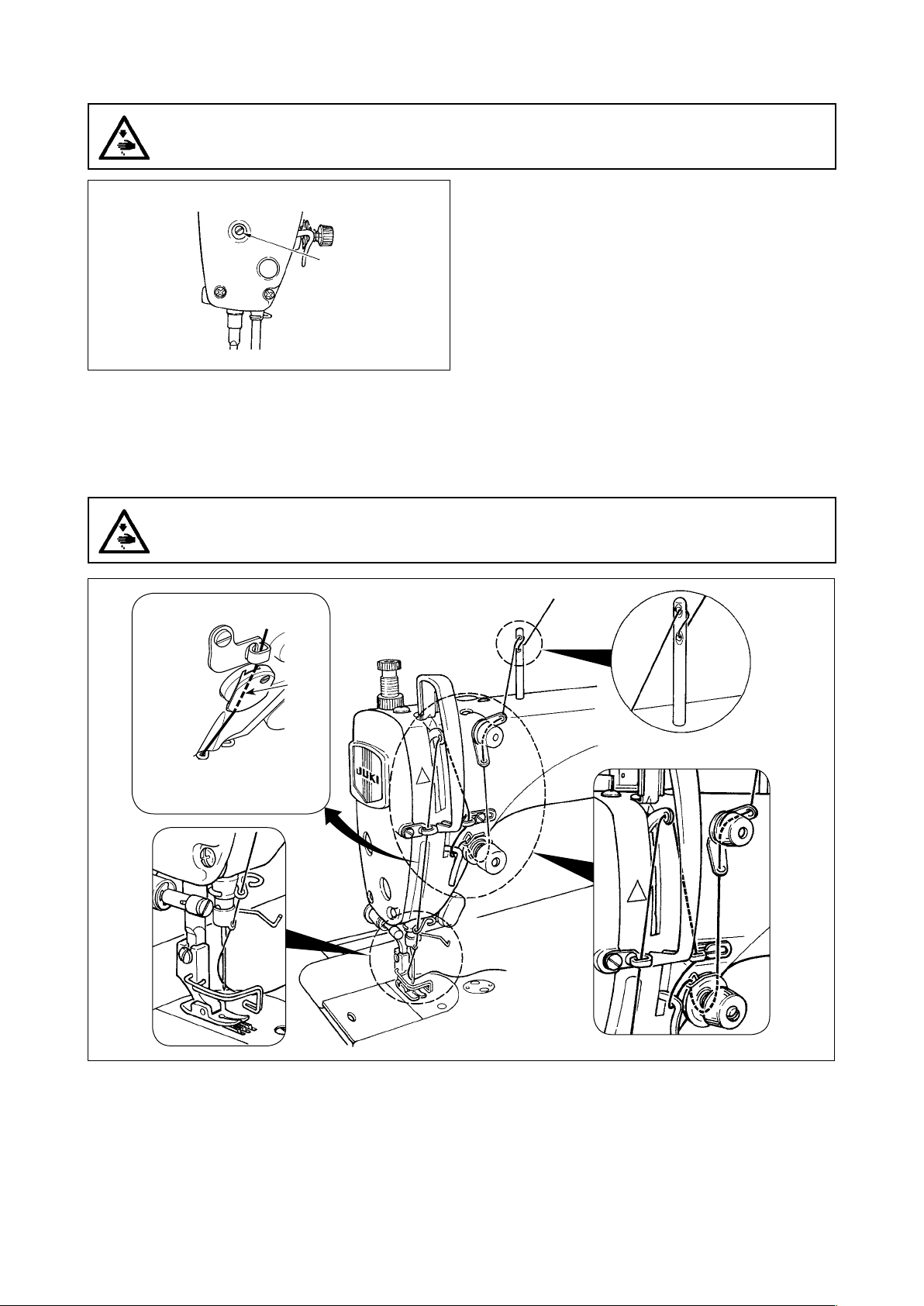
18. Threading the machine head
WARNING :
Be sure to turn the power OFF before the following work in order to prevent personal injury due to
unintentional starting of the sewing machine.
1) Loosen setscrew ❶, and adjust the presser bar
height or the angle of the presser foot.
2) After adjustment, securely tighten the setscrew
❶.
[NB type]
A
(Note)
Be sure to pass the thread
through the section A.
– 14 –
19. Thread tension
❶
B
❷
A
❸
E
F
(1) Adjusting the needle thread tension
1) The length of thread remaining at the needle tip
after thread trimming is shortened by turning tension regulating nut No. 1 ❶ clockwise in direction
A.
2) It is lengthened by turning the nut counterclockwise in direction B.
3) The needle thread tension is increased by turning
tension regulating nut No. 2 ❷ clockwise in direction C.
4) It is decreased by turning the nut counterclockwise in direction D.
C
D
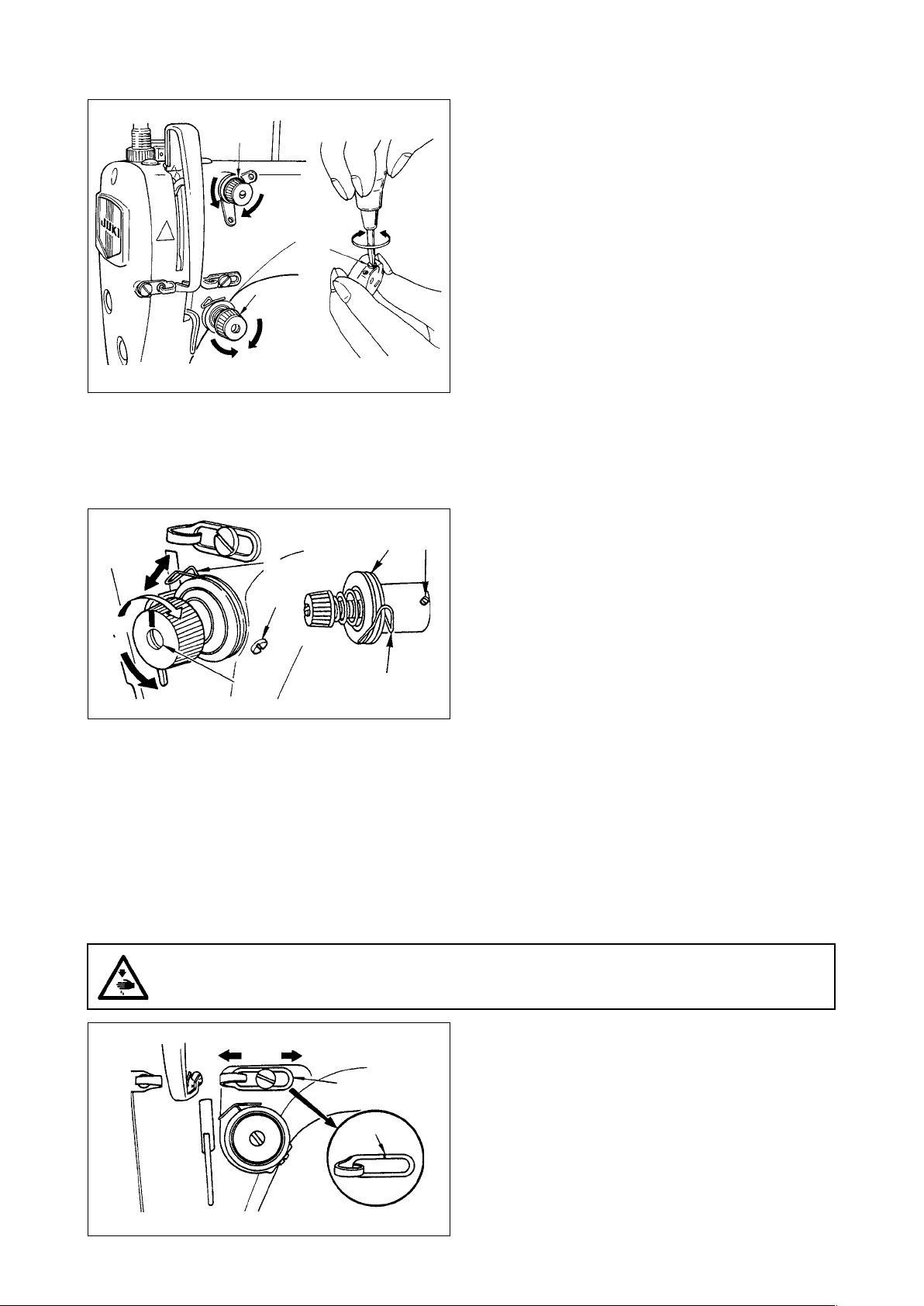
20. Thread take-up spring
❶
❷
A
B
❸
❶
❺
❹
(2) Adjusting the bobbin thread tension
1) The bobbin thread tension is increased by turning
tension regulating screw ❸ clockwise in direction
E.
2) It is decreased by turning the screw counterclockwise in direction F.
(1) Changing the stroke of thread take-up
spring ❶
1) Loosen setscrew ❷.
2) As you turn tension post ❸ clockwise (in direction A), the stroke of the thread take-up spring
will be increased.
3) As you turn tension post ❸ counterclockwise (in
direction B), the stroke will be decreased.
(2) Changing the pressure of thread take-up
spring ❶
1) Loosen setscrew ❷, and remove thread tension
asm. ❺.
2) Loosen setscrew ❹.
3) As you turn tension post ❸ clockwise (in direction A), the pressure will be increased.
4) As you turn the tension post ❸ counterclockwise
(in direction B), the pressure will be decreased.
21. Adjusting the thread take-up stroke
WARNING :
Be sure to turn the power OFF before the following work in order to prevent personal injury due to
unintentional starting of the sewing machine.
A
B
❶
C
1) When sewing heavy-weight materials, move
thread guide ❶ to the left (in direction A) to
increase the length of thread pulled out by the
thread take-up.
2) When sewing light-weight materials, move thread
guide ❶ to the right (in direction B) to decrease
the length of thread pulled out by the thread takeup.
3) Normally, thread guide ❶ is positioned in a way
that marker line C is aligned with the center of
the screw.
– 15 –
Loading...