


APW-193N

•JUKI
From the library of: Superior Sewing Machine & Supply LLC
Automatic
(Simpiified
Lockstitch
Operation
APW-193N
ENGINEER'S
Weiting
Type)
MANUAL
Machine
PREFACE
From the library of: Superior Sewing Machine & Supply LLC
This
Engineer's
This
manual
for the maintenance personnel and operators at a ganneni factory.
Itis
advisabletouse
sewing machinesofthese models.
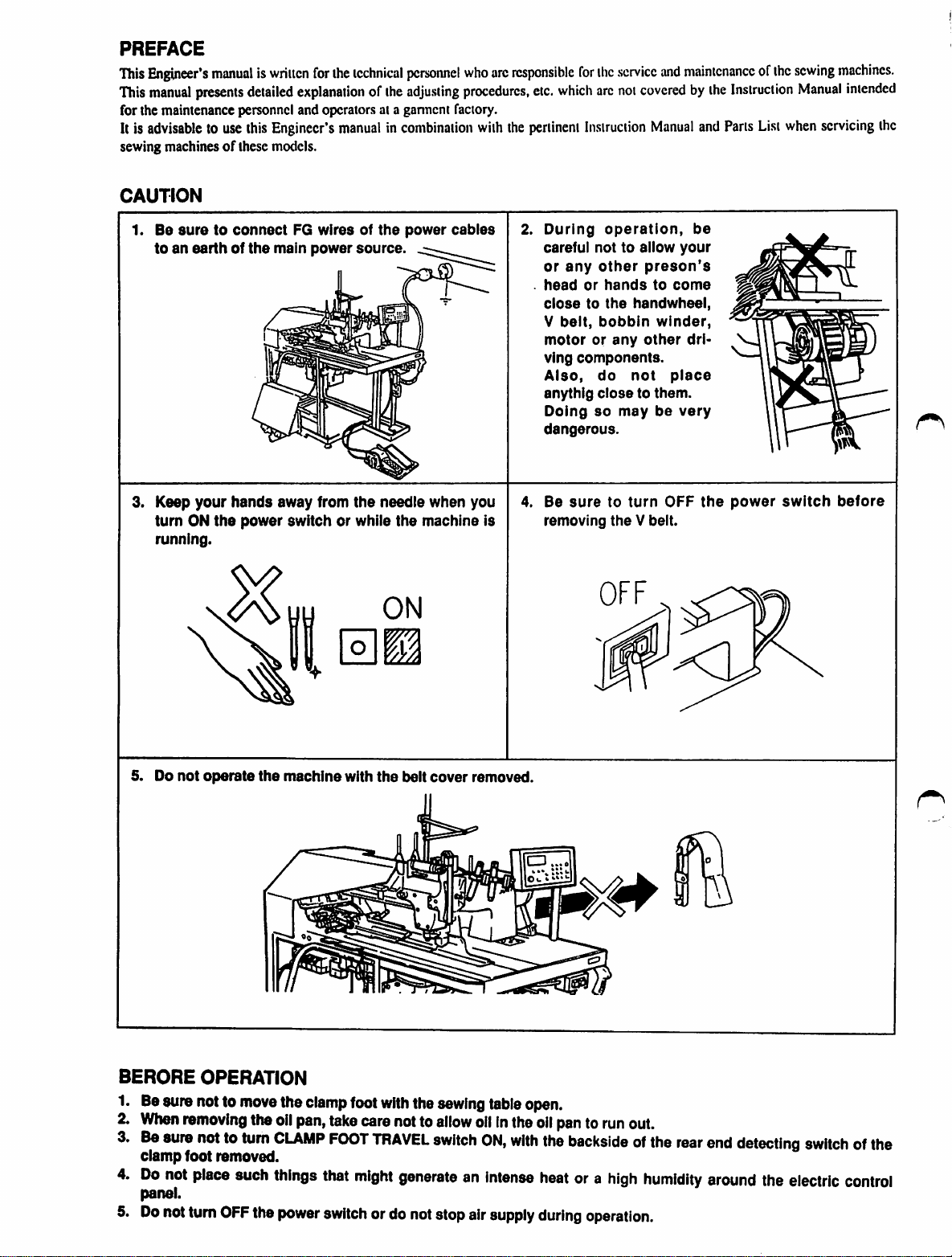
CAUTION
1.
Be
toanearthofthe
manualiswriitcn
presents
suretoconnect
detailed
this
for
ihe
explanationofthe
Engineer's
main
manualincombination
FG
wiresofthe
power
technical
source.
personnel
adjusting
power
cables
who
procedures,
with
are
responsible
the
pertinent
2.
for
the
service
etc.
which
arc
not
coveredbythe
Instruction
During
careful not to allow
or
head
closetothe
V
motororany
ving
Also,
anythig
Doing
dangerous.
operation,
any
other
or
hands
belt,
bobbin
components.
do
closetothem.
so
handwheel,
not
may
and
maintenanceofthe
Manual
and
be
your
preson's
to
come
winder,
other
dri-
place
be
very
Instruction
Parts
List
sewing
Manual
when
machines.
intended
servicing
the
3. Keep
turnONthe
running.
5. Do
not
your
operate
hands
power
away from
switch or while
the
machine
the
with
needle
the
ON
m
the
belt
when you
machine Is
cover
removed.
4. Be
removing
suretoturn
theVbeit.
OFF
the
power
switch
before
BERORE
1. Besure notto
When
Be
clamp
Do
panel.
Do
OPERATION
removing
sure
nottoturn
foot removed.
not
place
notturn
OFF
move
the
such
the
the
clamp
oil
pan,
take
CLAMP
things
power
FOOT
that
switch
foot
with
the
carenotto
TRAVEL
might
switch
generateanIntense
ordo notstopair
sewing
allow
table
oilInthe
ON,
with
supply
open.
oil
pantorun
the
backsideofthe
heat
during
ora
out.
high
operation.
rear
humidity
end
detecting
around
the
electric
switchofthe
control
CONTENTS
From the library of: Superior Sewing Machine & Supply LLC
1.
SPECIFICATIONS
(1) Mechanical Specifications 1
(2) Electrical Specifications I
2.
CONFIGURATIONOFTHE
3.
INSTALLATION
MACHINE
(1) Levelling the machine 3
(2) Installingthe accessorycomponents 3
(3) Installing the stacker and adjusting it 4
(4) Attaching the optional devices and adjusting them 9
4.
CONNECTIONOFELECTRIC
POWER
SOURCE
AND
AIR
SUPPLY
SOURCE
(1) Connection of electric power source 12
(2) Connection of the air supply source 12
5.
OPERATION
PANEL
SWITCHES
AND
INDICATOR
LAMPS
(1) Operation panel switches 13
(2) Manual
mode
and automatic
mode
(3) Example ofsetting data on cycle sewing 35
(4) Example of setting data for slant flap sewing 37
6.
HOWTOSET
OPERATE
THE
THE
MATERIALTOBE
SWITCHES
DURING
SEWNONTHE
SEWING
MACHINE
AND
(1) How to perform welting and sewing welts with flaps 38
(2) How to sew a welt pocket with the binder raised 39
7.
EXPLANATION
OF
VARIABLE
RESISTORS
AND
DIP
SWITCHES
(1) Explanation of function 42
(2) Setting for special-purpose functions using DIP switches 44
8.
CROSS
(I)
9.
MARK
LAMPS
Crass (+) mark lampsfor settingsewing 49
AIR
CONTROL
SWITCHES
(1) Foot valve switch 50
(2) Pointsrequiringspecial attentionwhen operatingthe air cylinder independently
(Manual
10.
PEDAL
11.
POINTSTOBE
12.
TEMPORARY
(1)
Temporary
(2)
Automatical
operationof thesolenoidvalve) 50
SWITCH
AND
KNEE
NOTED
STOP
BEFORE
.stopbymanual
temporary
.stop
SWITCH
OPERATION
operation
OPERATION
(3) List of alarm codes 55
(4) Listof check codes 60
1
2
3
12
13
16
38
42
49
50
51
53
54
54
54
13.
From the library of: Superior Sewing Machine & Supply LLC
ADJUSTMENTS
(1)
Binder
(2)
Adju.siing
(3)
Clamp
(4) Adju.sting the comer knife
14.
MAINTENANCE
(1)
Pneumatic
(2)
Sewing
(3)
Maintenance
(4)
Precautions
15.
SEWING
(1)
Removing
(2)
Lubrication
(3)
Needles
(4)
Threading
(5)
Thread
(6)
Adjasting
(7)
Relationofthe
(8)
Adju.siing
(9)
Adjasting
(10) Po.sition of the thread tension relea.serod
(11)
Adjasting
(12)
Po.sitionofthe
(13)
Timingofthe
(14)
Howtochange
16. ELECTRICAL CONTROLCOMPONENTS 93
(1)
Electrical
(2)
Indicationofthe
(3)
Relation
(4)
Explanationofthe
(5)
Howtoadjast
17. TROUBLESANDCORRECTIVE
18. FLOW CHART OF STANDARD OPERATION 104
19. ATTACHED MATERIALS 105
(1)
Control
(2)
Power
(3)
Pneumatic
clamp
foot,
welting
AND
.sy.stems
machine
and
for
the
MACHINE
the
oil
and
the
machine
tension
the
po.sitionofthe
hooktothe
the
needle
the
center
the
bobbin
.synchronizer
thread
control
between
the
box
connection
circuit
diagram
circuit
foot
traveling
patch
folding
INSPECTION
head
inspectionofthe
compre.s.sed
HEAD
pan
the
timing
belt
head
and
needle
needle
thread
knife,
knife
thread
knife
tension
over
the
flap
components
operation
LEDs
photoelectric
diagram
.servo
ofthe
and
input/output
driver
diagram
mechani.sm
plate
and
electrical
air
.supplying
windingabobbin
bar
frame
center
knife
di.scto.start
pre.sserofthe
cellofthe
MEASURES
needle
"floating"
thread
ofthe
flap
flap
pre.s.ser
.sy.stem.s
(the
air
and
bobbin
folding
plate
breakage
CPU
.sensor
mechanism
supply
.source)
thread
detecting
circuit
board
devices
knife
circuit
66
68
79
79
79
79
80
81
81
82
83
83
86
86
87
88
89
91
92
92
92
93
95
95
96
97
98
105
106
107
1.
From the library of: Superior Sewing Machine & Supply LLC
SPECIFICATIONS
(1) Mechanical
• Sewing muchine:
• Sewing speed:
• Stitch length:
• Types of welt:
•
Typesofwelts:
• Pocket lip length
(Welt length):
• Welting width (needle gauge):
•
Needles:
•
Thread:
•
Hook:
• Thread take-up lever:
•
Needle
•
Cloth
•
Control:
• Safety mechanism:
• Lubricating oil:
• Operating air pressure:
• Air consumption:
•
Dimeasionsofthe
• Weight:
Specifications
bar
stroke:
feed
mechanism:
machine:
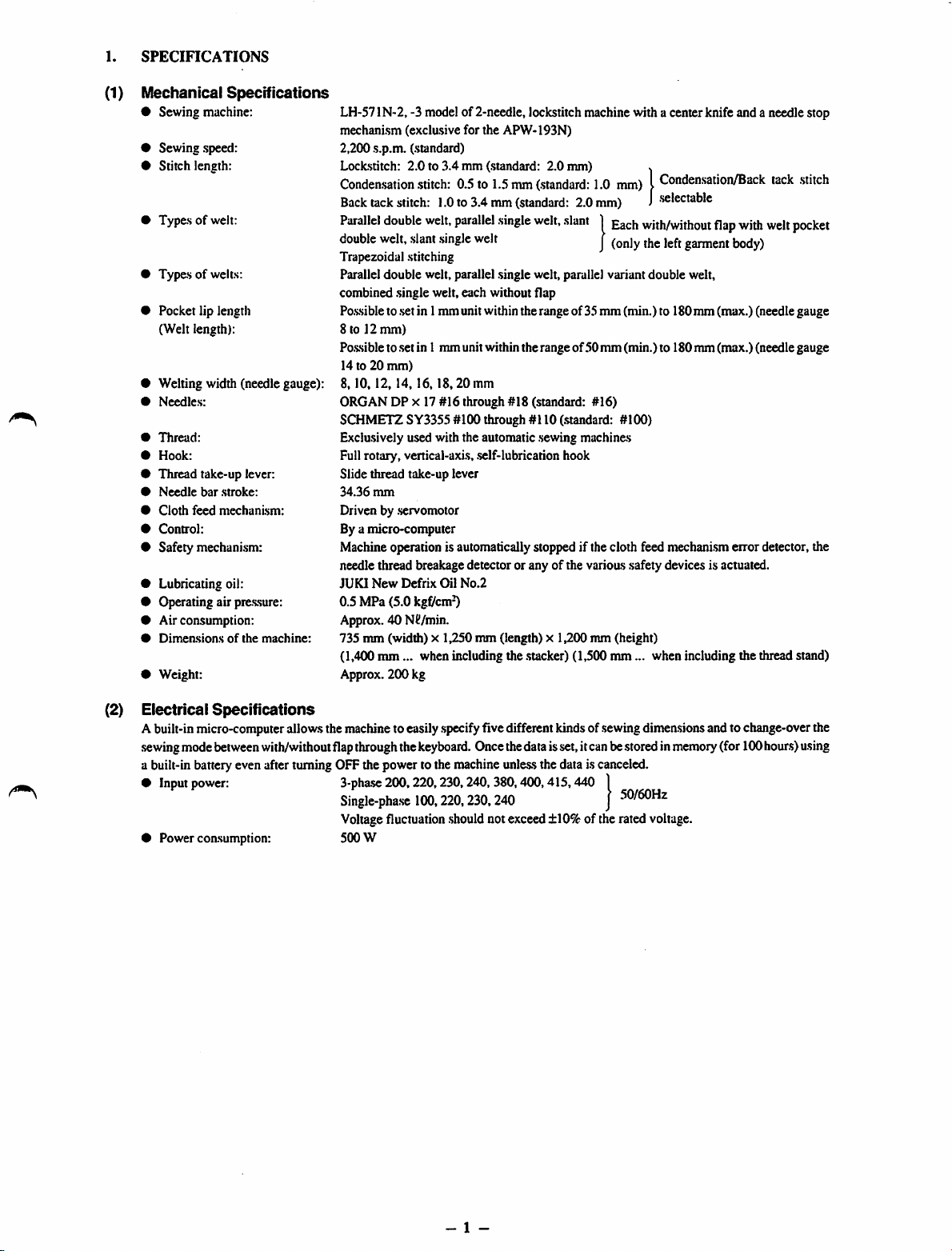
LH-571N-2, -3 modelof 2-needle, lockstitch machine with a center knife and a needle stop
mechanism (exclusive for the APW-193N)
2,200 s.p.m. (standard)
Lockstitch:
Conden-sation
Back
Parallel
double
Trapezoidal stitching
Parallel double welt, parallel .single welt, parallel variant double welt,
combined .singlewelt, each without flap
Po.s.sible
8 to 12
Po.s.sible
14 to 20
8.10.12,
ORGAN DP X 17 #16 through #18 (standard: #16)
SCHMETZ SY3355 #100 through #110 (.standard: #100)
Exclusively used with the automatic .sewing machines
Fullrotary, vertical-axis, .self-lubrication hook
Slide thread take-up lever
34.36
Driven by .servomotor
Bya micro-computer
Machineoperation is automaticallystopped if the cloth feed mechanismerror detector, the
needle thread breakage detector or any of the varioas safety devices is actuated.
JUKI
0.5MPa(5.0
Approx. 40 Nd/min.
735 mm (width) x 1,250 mm (length) x 1,200 mm (height)
(1,400
Approx. 200 kg
2.0to3.4
tack
stitch:
double
welt,
slant
to.setin 1mm unit withintherange of 35
mm)
to.setin 1 mm unitwithin the range of50 mm (min.) to 180mm (max.) (needle gauge
mm)
14,16,18,20
mm
New
Defrix
mm...
mm (standard: 2.0 mm) x
.stitch:
0.5to1.5mm(.standard:
1.0to3.4mm(standard:
welt,
parallel
single
single
welt
mm
Oil
No.2
kgf/cm-0
when including the .stacker)(1,500
welt,
slant1gach
2.0
1.0
mm)ICondensation/Back
mm)J.selectable
with/without
j
mm(min.)to
mm...
when including the thread stand)
flap
with
garment
180mm (max.) (needlegauge
body)
tack
welt
.stitch
pocket
(2) Electrical
Abuilt-inmicro-computerallowsthe machineto easily
sewingmode
a built-in battery even after turning OFF the power to the machine
•
Input
• Power coasumption: 500 W
Specifications
between
power:
with/withoutflapthroughthe
3-phase
200,220,230,240,
Single-phase
Voltagefluctuation
100,220,230,240
.specify
keyboard.
.should
fivedifferentkindsof
Oncethedataisset,itcanbestoredin
unle.ss
the data is canceled.
380,400,415,440
notexceed±10%of the rated voltage.
.sewing
dimensionsand tochange-overthe
|
J
50/60Hz
memory
(for100hours)using
- 1 -

2.
From the library of: Superior Sewing Machine & Supply LLC
CONnCURATION
The APW-I93N consists mainly of the following units;
O
Frame
and
(Frame,sewing table,covers, foot switch etc.)
®
Clamp
® Comer knife unit
0
Binder
0
Pneumatic
0 Stacker unit
0
Sewing
0 Electriccontrolunit(Control box)
O Oil
pan
0
Operation
0 Powerswitch
structural
foot
unit
unit
(Binder
control
machine
panel
OF
THE
components
and
feed
components
unit
head
MACHINE
mechanism
(Pneumatic
andits
control
driving
devices
components)
and
piping.s)
Fig. 1
With
this
machine,
place andoperating the switches on the operation panel.
youcando
desired
welting
work
simplybysetting
- 2 -
materials
(garment
body,
interlining
piece,
welting
patch
etc.)
in
3.
From the library of: Superior Sewing Machine & Supply LLC
INSTALLATION
(1) Levelling
(2) Instaliing
the
machine
the
accessory
Fig. 2
components
Yellow
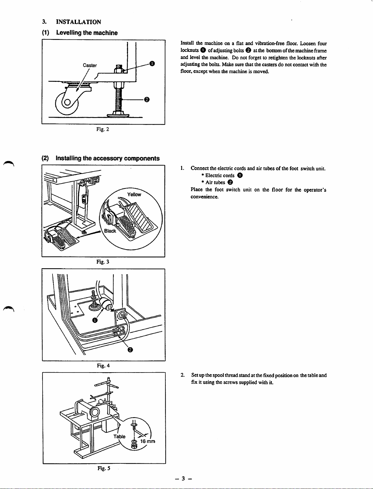
Install
the
locknuts
machineona
O of
adjusting
flat
bolts
and
vibration-fiee
O at
the
bottom
floor.
ofthe
Loosen
machine
four
frame
and level the machine. Do not forget to retighten the locknuts after
adjusting the bolts. Make sure that the casters do not contact with the
floor, except when the machine is moved.
1.
Connect
the
electric
cords
and
air
tubesofthe
foot
switch
unit.
^ Electriccords O
*
Air
tubes
Place the foot switch unit on the floor for the operator's
convenience.
Black
2. Set upthespoolthreadstandat thefixedpositionon the tableand
fix it using thescrewssupplied with it.
Table
Rg.5
1
16
mm
- 3 -
(3)
From the library of: Superior Sewing Machine & Supply LLC
Installing
Grasping stacker (SP-25N)
the
stacker
and
adjusting
it.
Frameofthe
unit
Barstacker
main
280
(SP-26N)
Tableofthe
|
Tableofthe
main
main
unit
unit
Sub-table
Safety pipe
Air
tube O
15P connector (2)
Stacker
main
unit
panel
frame
on the
Frameofthe
unit
230
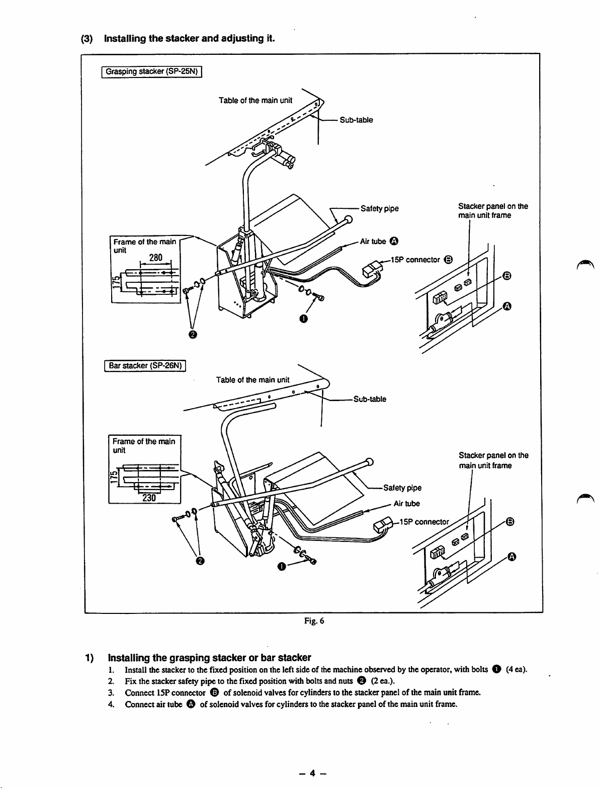
1) Installing
1.
Install
2. Fix
3.
4.
the
Connect
Connect
main
the
grasping
the
stacker
stacker
safety
15P
connector
airtube O of
stackerorbar
tothe
fixed
pipe
® of
solenoid
positiononthe
tothe
Hxed
solenoid
valves
stacker
position
valves
for
cylinders
left
sideofthe
with
for
Fig. 6
bolts
and
cylinders
tothe
•Sut)-table
machine
observedbythe
nutsO(2ea.).
tothe
stacker
stacker
panel
Safety pipe
Air
15P
panel
ofthe
ofthe
main
tube
connector
operator,
main
unit
unit
frame.
Stacker
main
with
frame.
panelonthe
unit
bolts
frame
O (4
ea).
- 4 -
2) Adjusting
From the library of: Superior Sewing Machine & Supply LLC
Workpiece
>-ii
the
r (D
grasping
Fig. 7
stacker
(SP-25N)
j—Workpiece
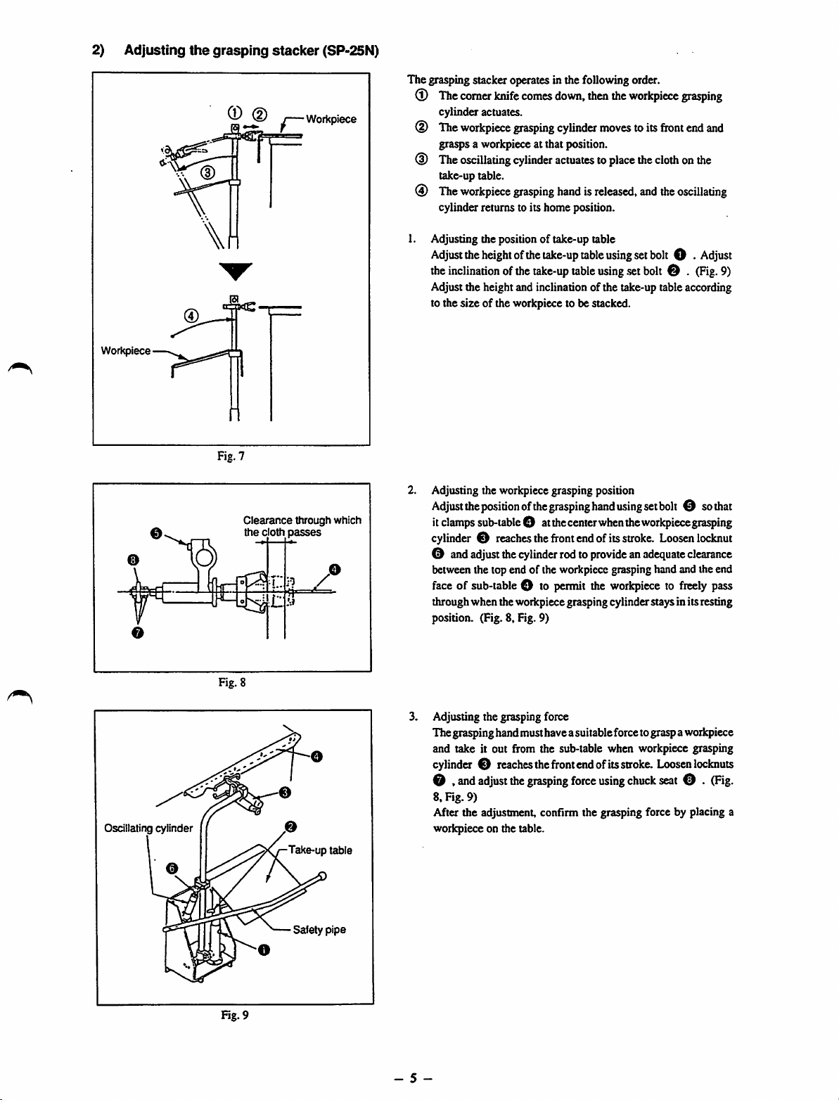
The grasping stacker operates in the following order.
®
The
comer
knife
comes
down,
then
the
workpiece
cylinder actuates.
(D The
(D
(i)
1.
workpiece
gra^s
The
oscillating
take-up table.
The
workpiece
cylinder returns to its home position.
Adjusting the position of take-up table
Adjust
the
the
inclination
Adjust the height and inclination of the take-up table according
to the
size
grasping
a workpiece at that position.
cylinder
grasping
height
ofthe
ofthe
of the workpiece to be stacked.
cylinder
actuatestoplace
handisreleased,
take-up
table
take-up
table
moves
using
using
.set
toits
front
the
clothonthe
and
the
setbolt O •
bolt
0 .
grasping
end
and
oscillating
Adjust
(Fig.
9)
Oscillating cylinder
Fig. 8
Clearance
the
cloth
through which
passes
o
Take-up table
2.
Adjusting the workpiece grasping position
Adjust
the
positionofthe
it
clamps
sub-table
cylinder0reaches
0 and
adjust
the
between the top end of the workpiece grasping hand and the end
face
of sub-table O to
throughwhen the workpiecegrasping cylinder staysin itsresting
position. (Fig. 8, Fig. 9)
3.
Adjusting the grasping force
Thegrasping handmusthavea suitableforce tograsp aworkpiece
and take it out from the sub-table when workpiece grasping
cylinder0reaches
0 ,
and
adjust
8, Fig. 9)
After the adjustment, confirm the grasping force by placing a
workpiece on the table.
O atthe
cylinder
the
grasping
grasping
the
front
the
hand
center
endofits
rodto
provideanadequate
permit
the
front
endofits
force
using
set
bolt
when
the
workpiece
stroke.
Loosen
workpiecetofreely
stroke.
Loosen
using
chuck
seat
0 so
grasping
locknut
clearance
pass
lockouts
0 .
(Hg.
that
Safety
pipe
Fig. 9
- 5 -
3) Adjusting
From the library of: Superior Sewing Machine & Supply LLC
Workpiece
the
bar
stacker (SP-26N)
Presser
Oscillating
Workpiece
arm
arm
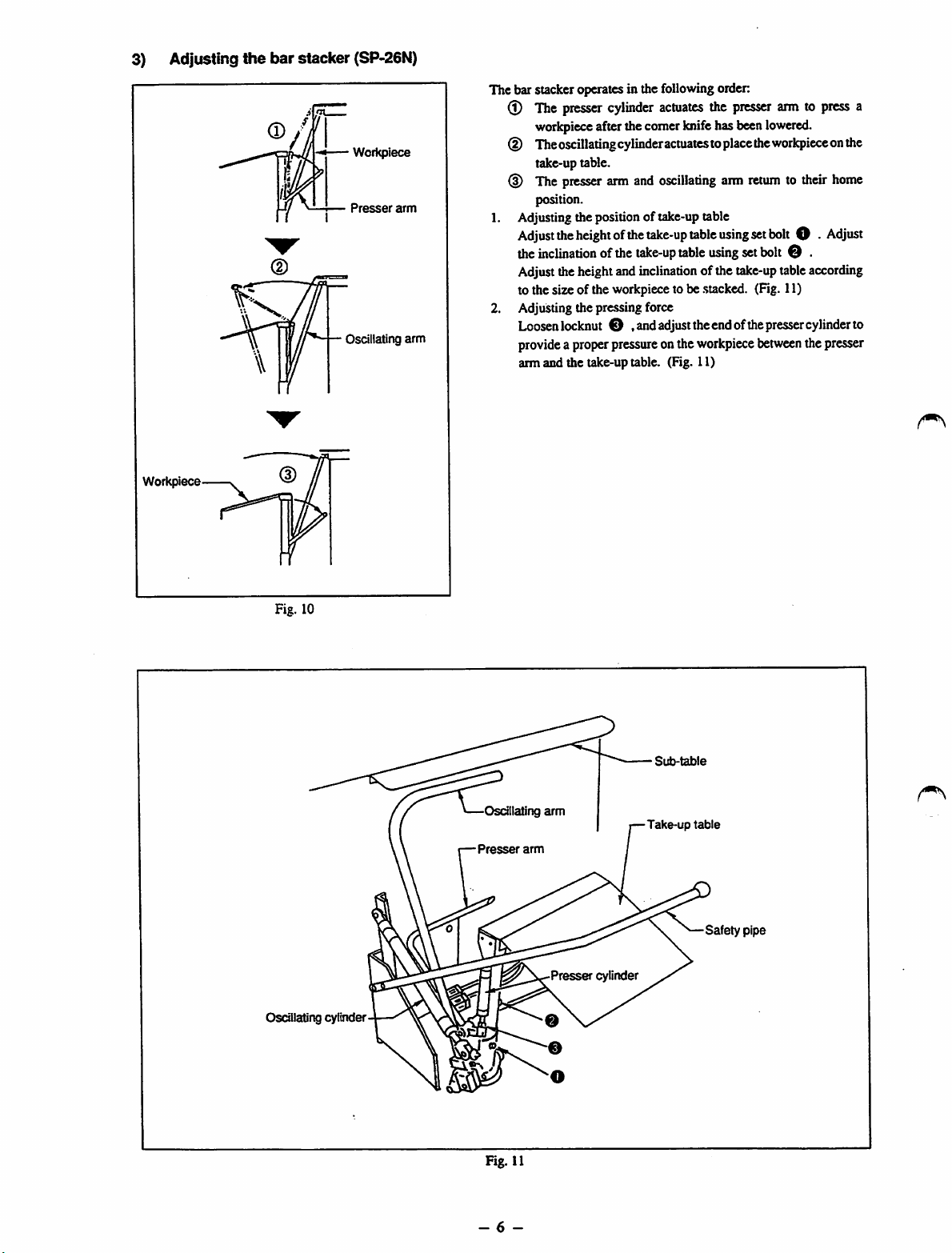
The bar stacker operates in the followingorder:
(l) The
(D Theoscillatingcylinder
(D The
1. Adjusting the position of take-up table
2. AdjuSdng the pressing force
presser
workpiece
take-up table.
position.
Adjust
the
the
inclinadon
cylinder
afterthecomerknifehasbeen
presser
arm and
heightofthe
ofthe
actuates
actuates
oscillating
take-up
take-up
table
table
the
toplacethe
using
using
Adjusttheheightandinclination of the
to the size of the workpieceto be
.stacked.
presser
arm
take-up
Loosenlockout O .andadjusttheendofthe
provide
a properpressure onthe
arm and the take-up table. (Fig. 11)
workpiece
arm to
lowered.
workpiece
returntotheir
set
bolt
O •
set
bolt
O .
tableaccording
(Fig. 11)
presser
between
press
onthe
home
Adjust
cylinderto
thepresser
a
Fig. 10
Oscillating cylinder
Osdilating
Presser
arm
arm
Presser
0
cylinder
•
Sub-table
-Take-up
table
Safety
pipe
Fig. 11
- 6 -

4) Attaching
From the library of: Superior Sewing Machine & Supply LLC
1. Attach the roller stacker on the left-hand side face of the main unit frame, and fix it with three screws taking care to set the
roller in parallel to the main unit table.
Roller
Main
stacker
the
unit
attaching
roller
frame
stacker
position
PJ304040505
(SP-36N)
^6
tube
2.
Pa.ss
theairtube O for
connector©for
© in
Fig.
3.
Connect
illustrated in the figure below.
air
shown
tube
roller
above
O .
Fig. 12
roller
oscillating
oscillating
inthe
written
15P
connector©and2Pconnector©respectively
Stackerpanel on the
main
unit
cylinder
frame
solenoid
order.
and
valve,
outputcablefordrivingroller,theupperdetection
the
motor
power
cable
* Whenattachingtherollerstackerto themachine, puta plug toone
side of the hole for quick-coupling
ofthe2P
connectorOthrough
tothe
stacker
panel
ofthe
joint
sen.sor
holes
main
cableofthe
® , ®
unit
frame
and
as
Fig. 13
- 7 -
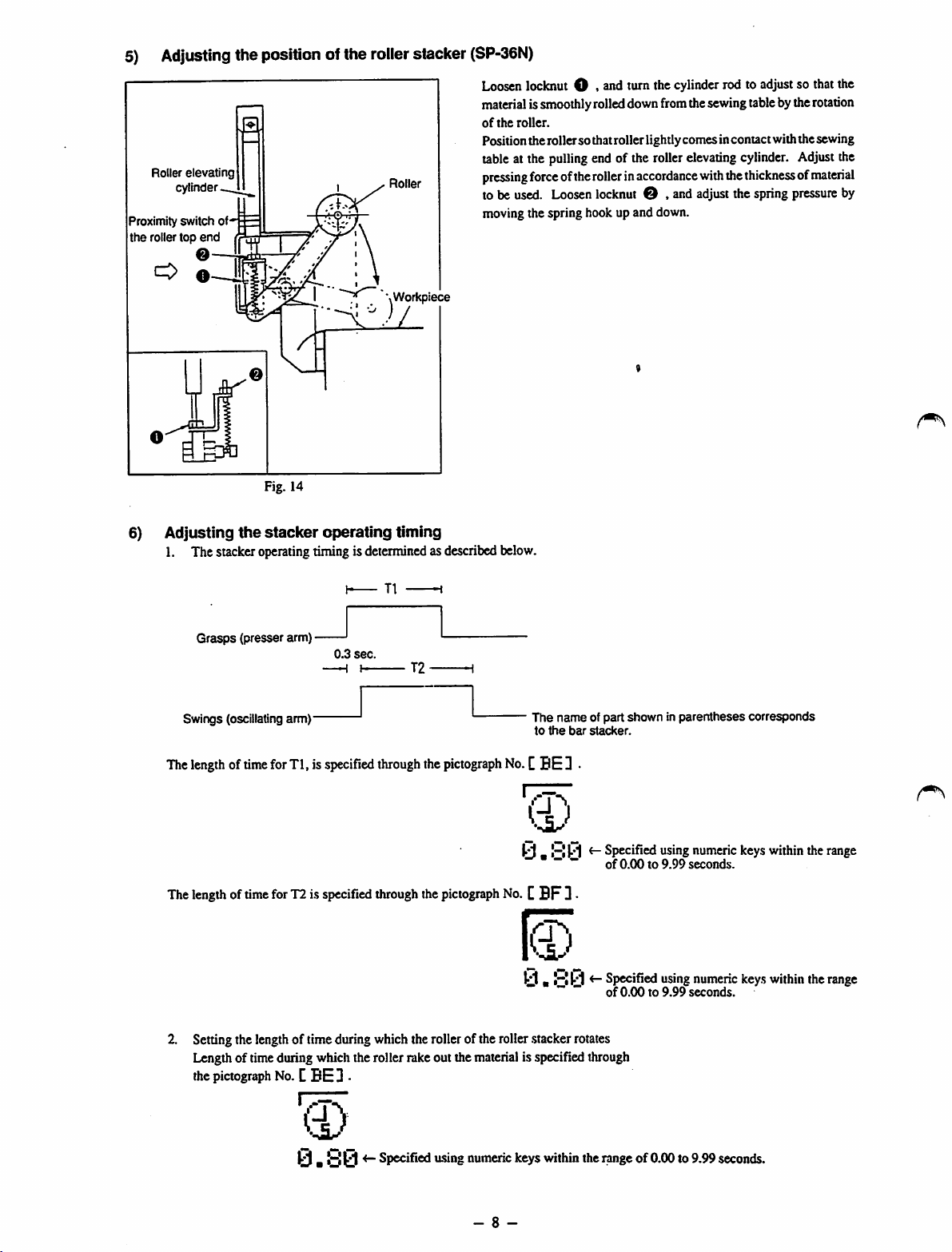
5) Adjusting the position of the rollerstacker
From the library of: Superior Sewing Machine & Supply LLC
Roller
elevating
cylinder
Proximity switch of*'
the roller top
O
end
©-
0-
Fig. 14
Roller
\Workpiece
(SP-36N)
Loosenlockout O . end turn the cylinderrod to adjustso thatthe
material
issmoothlyrolleddownfromthesewingtablebythe
of
the
roller.
Positiontherollersothatroller lightlycomesincontact withthe sewing
tableat the
pressing
to be
moving the spring hook up and down.
force
used.
pulling
end of the rollerelevating cylinder. Adjustthe
ofthe
rollerinaccordance
Loosen
locknut
© , andadjustthe spring
with
the
thicknessofmaterial
rotation
pressure
by
6)
Adjusting
1. The stackeroperatingtiming is determinedas described below.
Swings (oscillating
The
The
the
Grasps
(presser arm) •
lengthoftime
lengthoftime
stacker
arm)'
for
Tl, is
for
T2is
operating
0.3
sec.
-H
I T2
specified
specified
timing
T1
through
through
the
pictograph
the
pictograph
The name of part shown in parenthesescorresponds
to
the
bar
stacker.
No.
CBE D
y.y0
No.CBF
ti.yy
*" ~ ~ of 0.00 to 9.99 seconds.
~ *"
3
<-
Specified
of
0.00to9.99
<-
specified
using
using
numeric
seconds.
numeric
keys
keys
within
within
the
the
range
range
2. Setting the lengthof time during which the rollerof the roller.stackerrotates
Lengthof timeduring which the roller rake out the materialis specifiedthrough
the
pictograph
No.CBE3 •
Ci)
ir- Specified u.sing numeric keys within the rangeof0.00 to 9.99 seconds.
- 8 -
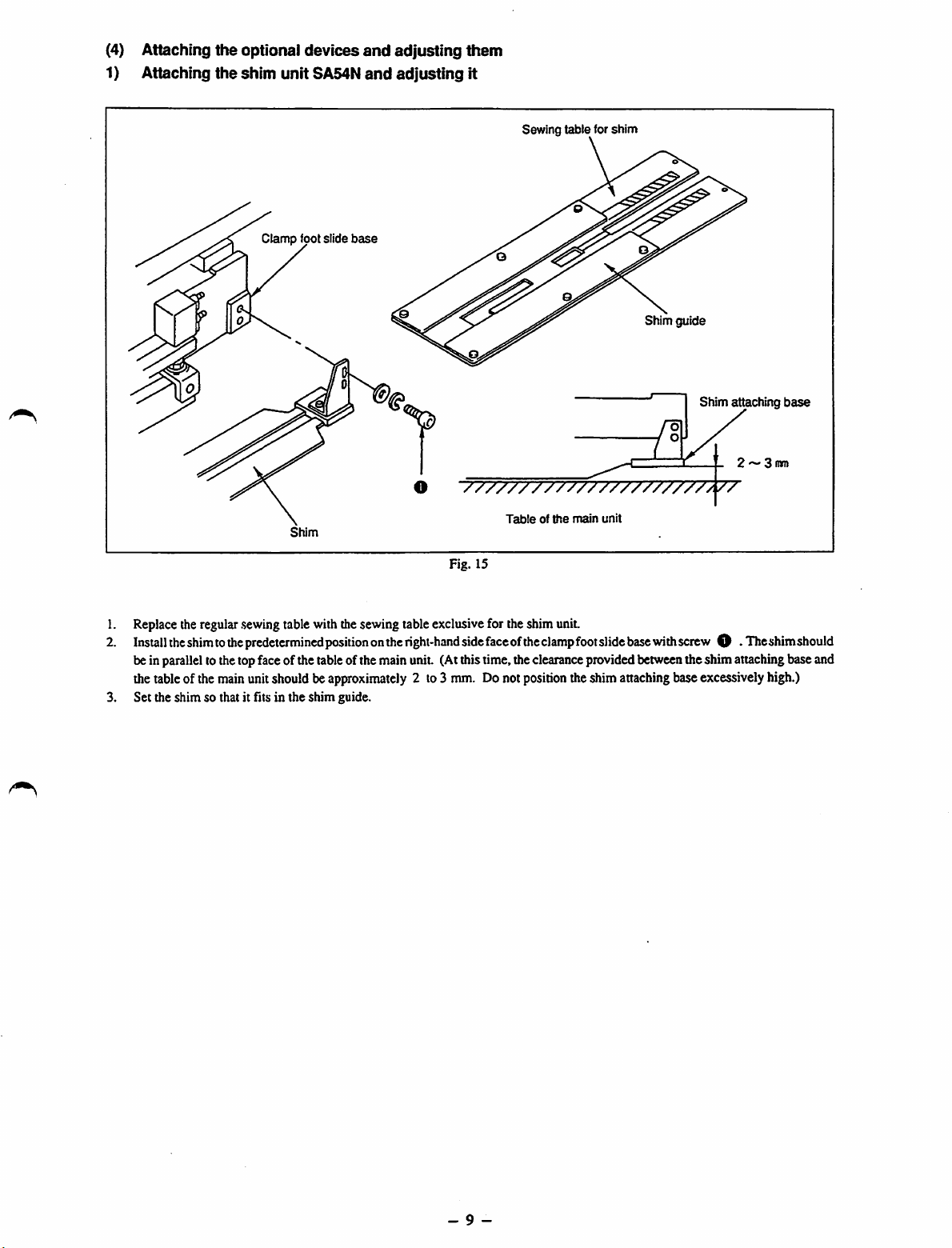
(4) Attaching
From the library of: Superior Sewing Machine & Supply LLC
1) Attaching
the
the
optional
shim
unitSA54N
Clamp
devices
foot slide
base
and
and
adjusting
adjusting
them
It
Sewing
table
for
shim
Shim guide
Shim attaching
2 ~ 3
O
"7777777777777777777777/77
side
Tableofthe
faceofthe
position
Shim
Fig. 15
1. Replacetheregular
2.
Install
the
shimtothe
beinparallelto thetopface of thetableof the main unit. (Atthistime,theclearanceprovidedbetweentheshim attachingbase and
thetableof themainunitshould be
3. Set the shim so that it fits in the shim guide.
.sewing
table withthesewing tableexclusivefor theshim unit.
predetermined
positiononthe
approximately
right-hand
2 to3 mm. Donot
main
unit
clamp
foot
slide
base
with
screw
O •
theshimattaching baseexcessively high.)
The
base
mm
shim
should
- 9 -
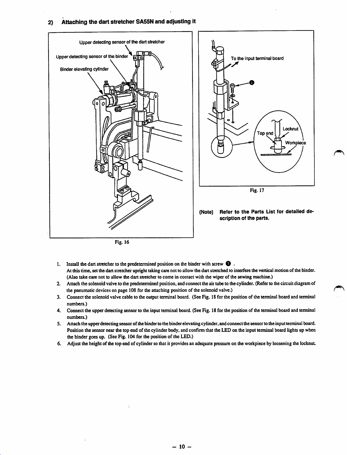
2) Attaching the dart stretcher
From the library of: Superior Sewing Machine & Supply LLC
Upperdetectingsensor ofthe dart stretcher
SA55N
and adjusting it
Upperdetecting sensor ofthe binder '
Binder
elevating
cylinder
\
To
(Note) Refer to
scriptionofthe
the
input terminal
Fig. 17
the
Parts
board
Locknut
Workpiece
List for detailed de
parts.
Fig. 16
Install
the
dart
stretchertothe
Atthis time, setthedan stretcheruprighttakingcarenotto allowthedan stretchedto interferetheverticalmotionof the binder.
(Also take care not to allow the
Attachthe solenoidvalveto the predetermined position,andconnecttheairtubeto the cylinder.(Referto thecircuitdiagramof
thepneumatic
Connect the solenoidvalve cable to the outputterminalboard. (SeeFig. 18for the positionof theterminalboardand terminal
3.
numbers.)
4.
Cormectthe upperdetectingsensor to the inputterminal board.(SeeFig. 18for the positionof the terminalboard and terminal
numbers.)
Attachthe upperdetectingsensor ofthe bindertothe binderelevatingcylinder,andconnectthesensor totheinputterminalboard.
Position the sensor near the top end of the cylinderbody,and confirm that the LED on the input terminal board lights upwhen
the binder goes up. (SeeFig. 104for the positionof the LED.)
Adjust the height of the top end of cylinderso that it provides an adequate pressureon the workpiecebylooseningthe locknut
6.
device.s
predetermined
dan
positiononthe
stretcher to come in contact with the wiper of the sewing machine.)
onpage 108for theattaching
binder
po.sition
of thesolenoidvalve.)
with
screw
O •
-
10
-
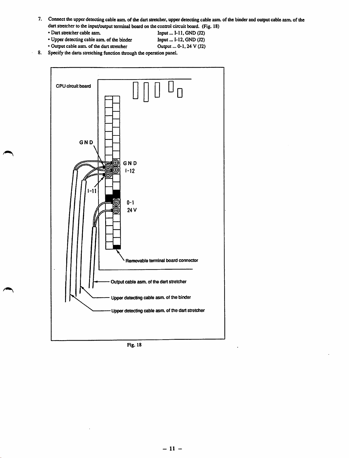
7.
From the library of: Superior Sewing Machine & Supply LLC
Connect
dartstretcher to the
• Dart stretchercableasm. Input...
• Upper detectingcable asm.of the binder Input...
• Output cable asm. of the dart stretcher Output...
Specifythedartsstretchingfunctionthroughthe operation panel.
CPU
the
circuit
upper
board
detecting
input/output
cable
asm.
terminal
ofthedart
boardonthe
stretcher,
DQDDd
GND
GN
D
control
upper
circuit
Ml,
M2,
detecting
board.
GND(J2)
GND(J2)
0-1,24
cable
V (J2)
asm.
(Fig.18)
ofthe
binder
and
output
cable
asm.ofthe
Removable
Output
cable
\
Upperdetectingcable asm.of the binder
Upp&detecting cable asm. of the dart stretcher
Fig. 18
terminal
asm.
of the dart stretcher
board
connector
-
11
-

4.
From the library of: Superior Sewing Machine & Supply LLC
CONNECTIONOFELECTRIC
POWER
(1)Connection of electric power source
Connect
the
power
supply
cordofthe
sure that the sewingmachine rotatesin thecorrectdirection.
[Rotating direction]
Turn
the
handwheel
directionofthe
from
the
handwhecl's
wires
(R.S.T.).
[Precaution in the electric connection]
1. Connect the ground wire to the earth without exception.
2. Quality of power
• Voltagefluctuation
• Rapid change of power voltagemaystop the machine.
• Surge
(2)
Connectionofthe
toletthe
handwheel.
Whenthewire
side)tostop
currentorelectromagnetic
air
supply
Air
operation
needle
down
the
mu.st
notexceed± 10%of the ratedvoltage.
paneltothe
toits
connectioniscorrect,
needle
inits
inductioninpower
source
cock
SOURCE
AND
power
lowest
dead
point
and
the
highest
dead
position.Ifnot,
may
Airpressure adjusting knob
AIR
SUPPLY
source
outlet
turn
handwheel
leadthe
SOURCE
(R.S.T.E.).
the
power
willrotateinthe
alternate
machinetomalfunction.
supply
When
switch
counterclockwise
the
connectionoftwo
connecting
"ON"as
you
the
lead
watch
direction
wires
wires,
make
the
rotating
(viewed
outofthree
Airsupply
Air
pressure
gauge
/
Airniter regulator
\ ^
Fig. 19
1. Securely connect the air supply
2.
Open
theaircockand
knob.
[Precautions for the air supply source]
Referto the article[(4) Precautionsforthecompressedairsupplying(theairsupplysource)devices]ofInspectionandmaintenance.
(Page 80)
adjust
theair
ho.se
(1/4")to the air cock locatedon the rear face of the machine.
pressure
sothattheair
pressure
gauge
indicates
S.O
kgf/cnF
(0.S
MPa)
bytheair
pre.ssure
adjusting
-
12
-
5.
From the library of: Superior Sewing Machine & Supply LLC
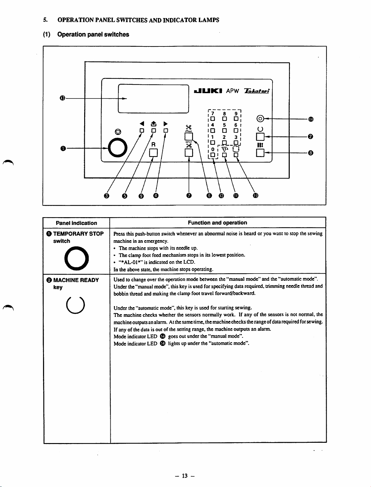
(1)
OPERATION
Operation
PANEL
panel
SWITCHES
switches
AND
INDICATOR
LAMPS
Panel
indication
O TEMPORARY
switch
STOP
o
0 MACHINEREADY
key
kJIIJIICI
APW
rL.Pj
T&kafort
T1
0 e o o 0 0 0
Function
Press this push-button switchwheneveran abnormalnoiseis heard or you wanttostop thesewing
machine in an emergency.
• The machinestops with its needle up.
• The clampfootfeed mechanism stops in its lowestposition.
•
"♦AL-01*"
In the above state, the machine stops operating.
Usedto
Under the"manualmode", this key is
bobbin thread and
change
is
indicatedonthe
overthe
operation
nnaking
LCD.
mode
u.sed
theclamp foot travel forward/backward.
and
operation
between
the"manualmode" andthe"automatic
for specifyingdata required, trimmingneedlethreadand
-0
0
©
mode".
O
Under the "automatic mode", this key is used for starting .sewing.
The machine checks whether the .sensors normally work. If anyofthe sensors is not normal, the
machine
outputsanalarm.Atthe
If anyof thedata isoutofthe
Mode
Mode
indicator
indicator
LED0goes
LED0lightsupunder
.same
.setting
out
-
13
time,
range,the
under
-
the
the
"manual
the
"automatic
machine
machine
checks
outputsan
mode".
mode".
the
range
alarm.
ofdata
required
for
sewing.
Panel
From the library of: Superior Sewing Machine & Supply LLC
indication
Function
and
operation
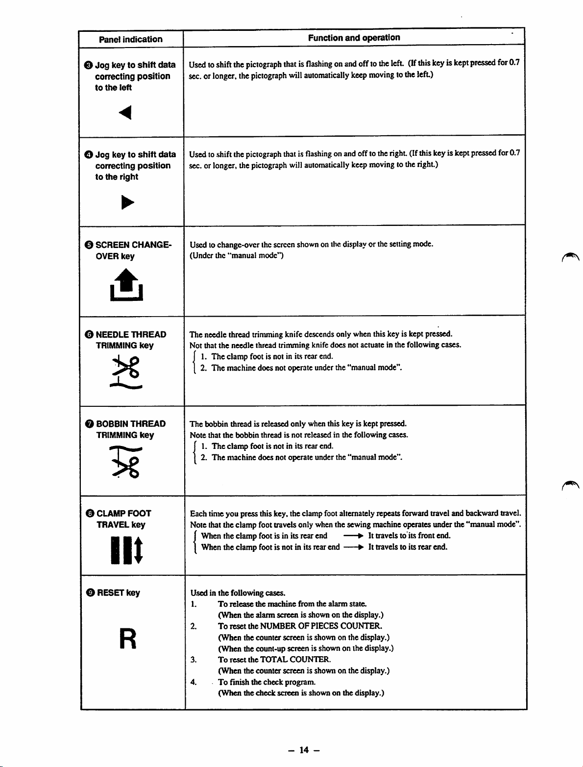
0
Jog
key to
shift
data
correcting
to
the
position
left
<
O
Jog
key to
shift
data
correcting
to
the
position
right
•
0 SCREEN CHANGE
OVER
key
0 NEEDLE THREAD
TRIMMING
key
Usedtoshift
sec.orlonger,
Used
sec.or
Usedtochange-over thescreen
(Under
The needle thread trimmingknife descendsonly whenthiskeyis keptpressed.
Not that the needle thread trinruningknife does not actuate in the following cases,
f1.The
[ 2. The
the
toshiftthe
longer,
the
"manual
clamp
machine
pictograph
the
pictograph
pictograph
the
pictograph
mode")
footisnotinits
does
not
thatisflashingonand
will
automatically
thatisflashingonand
will
automatically
shown
onthe
display
rear
end.
operate
under
the
"manual
offto
the
left.
keep
moving
totheleft)
offtotheright(If
keep
moving
tothe
or the
setting
mode".
(If
mode.
this
keyiskept
this
right.)
keyiskept
pressed
pressed
for
0.7
for0.7
0 BOBBINTHREAD
TRIMMING
0 CLAMP
TRAVEL
key
FOOT
key
III
0 RESETkey
R
The
bobbin thread is released only when this key is kept pressed.
Note that the bobbin thread is not released in the following cases.
J1.The
1 2.
Eachtimeyou pressthiskey.the clampfootalternately repeats
Notethatthe clamp foot travelsonly whenthe sewingmachine operatesunder the"manual mode".
j
1
Used in the following cases.
1.
2.
3.
4. To finish the check program.
clamp
footisnotinits
The
machine
When
the
When
the
To
(When
To
(When the counter screen is shown on the display.)
(When the count-up screen is shown on the display.)
To
(When the counter screen is shown on the display.)
(When
does
clamp
footisin
clamp
footisnotinits
release
the
machine
the alarm screen is shown on the display.)
reset
the
NUMBEROFPIECES
reset
the
TOTAL
the
check
rear
end.
not
operate
under
the
"manual
its
rear
end
rear
end
from
the
alarm
state.
COUNTER.
COUNTER.
screen is shownon the display.)
mode".
forward
•Ittravelstoits
• It
travelstoits
traveland backwardtravel.
front
end.
rear
end.
-
14
-
Panel
From the library of: Superior Sewing Machine & Supply LLC
indication
Function
and
operation
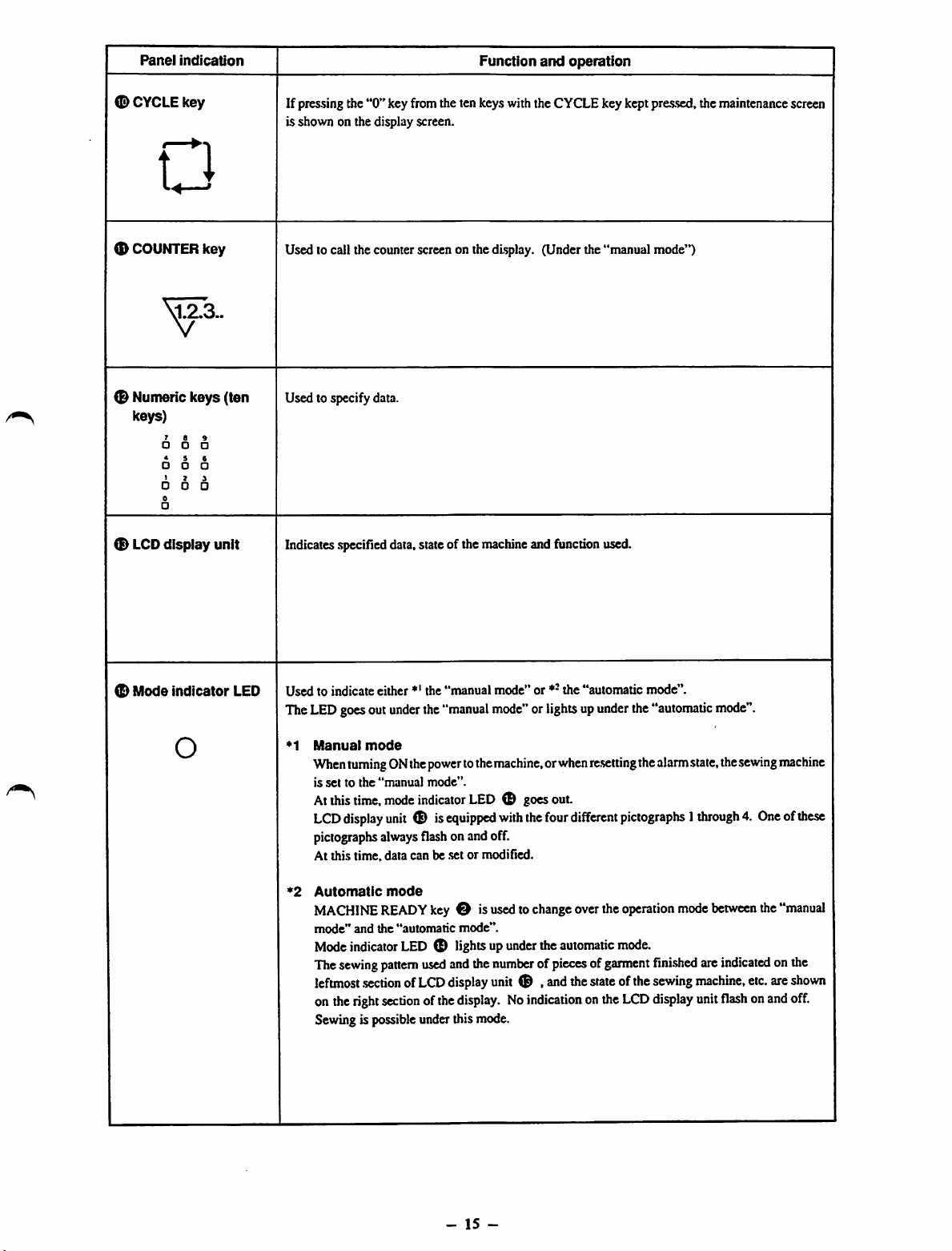
<D
CYCLE
key
n
<D
COUNTER
0 Nunteric keys (ten
keys)
®
LCD
key
5573..
• •
* i
• o
I 7
• •
0
•
display unit
If pressing the
is shown on the display screen.
Used to call the counter screen on the display. (Under the "manual mode")
Used to specify data.
Indicates
"0"
.specified
key from the ten keys with the CYCLE key kept pressed, the maintenance screen
data,state of the machineand function used.
(D
Mode
indicator
O
LED
Used
to indicate either *' the
The
LED
goesout
•^1
Manual
When
is
settothe
Atthis
LCD
pictographs
At this time, data can be set or modified.
*2
Automatic
MACHINE
mode"
Mode
The
sewing
leftmost
onthe
Sewingis possibleunder this mode.
under
mode
turningONthe
"manual
time,
mode
display
unit
always
mode
READY
and
the
"automatic
indicator
pattern
.sectionofLCD
right
section
"manual
the
"manual
power
tothe
mode".
indicator
® is
equipped
flash
onandoff.
key
O is
mode".
LED (D lightsup
used
andthe
display
ofthe
display.Noindication
mode"
or *-
the
"automatic
mode"
orlightsup
machine,orwhen
LED
O goesout.
with
the
usedtochange
under
theautomatic
four
le-setting
different
overthe
numberofpiecesofgarment
unit
® ,
and
the
state
onthe
mode".
under
the
"automatic
the
alarm
mode".
state,the
sewing
pictographs1through4.Oneofthese
operation
mode.
ofthe
LCD
mode
fini.shed
sewing
display
between
are
indicated
machine,
unit
flash
the
etc.
onand
machine
"manual
onthe
are
shown
off.
-
15
-
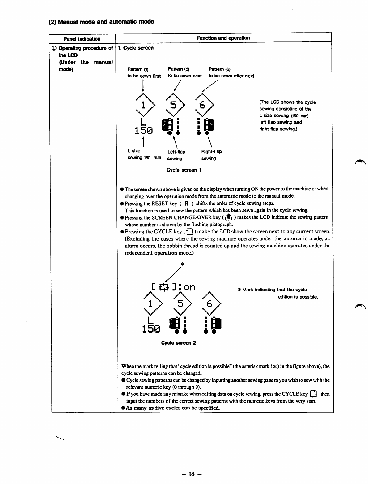
(2) Manual
From the library of: Superior Sewing Machine & Supply LLC
mode
and
automatic
mode
Panel
Operating
the
LCD
(Under
mode)
indication
procedure
the
manual
Funcdon
1.
Cycle
of
screen
Pattern
(1)
tobesewn
Pattern (5) Pattern (6)
first
tobesewn
next
and
tobesewn
operation
after
next
/
/\
'
.
V
L
m
I
I
150
I
L
size
sewing
150
mm
• ThescreenshownaboveisgivenonthedisplaywhenturningONthepowertothemachineorwhen
changing
•
Pressing
Thisfunctionis used to
•
Pressing
whose number is shown by the fla.shing pictograph.
•
Pressing
(Excluding
alarm
independent
overthe
theRESETkey ( R ) shiftstheorderofcycle
the
SCREEN
the
the
occurs,
Left-flap
sewing
Cycle
operation
CYCLE
cases
the
bobbin
operation
\
screen
.sew
CHANGE-OVER
key
where
mode.)
Right-flap
sewing
1
mode
fromthe
thepatternwhichhasbeen sewnagainin thecyclesewing.
(O )
make
the
threadiscountedupand
sewing
automatic
key
(|^)makes
the
LCD
machine
modetothe
show
operates
the
sewing
the
the
sewing
(The LCD
sewing
L
size
left
right flap
manual
.steps.
LCD
screen
under
shows
consistingofthe
sewing
flap
sewing
sewing.)
mode.
indicate
nexttoany
the
automatic
machine
operates
the
(ISO
and
the
sewing
current
mm)
cycle
mode,
under
pattern
screen.
an
the
CO
/"•s
*•!\ 'ir\
..1/
]:
on
b
s/
\ ^
*
Mark
indicating
that
the
cycle
editionispossible.
L
150
Cycle
screen
When the mark telling that "cycle edition is po.ssible"(the asterisk mark (4c) in the Hgure above), the
cycle .sewing patterns can be changed.
• Cycle .sewingpatternscan bechanged by inputting another .sewingpattern you wish to.sewwith the
relevant numeric key (0 through 9).
• If you have made any mi.stakewhen editing data on cycle .sewing,pre-ssthe CYCLEkey . then
input the numbers of the correct .sewingpatterns with the numeric keys from the very
•As
manyasfive
cycles
canbespecified
19
2
.start.
-
16
-
Panel
From the library of: Superior Sewing Machine & Supply LLC
indication
Function
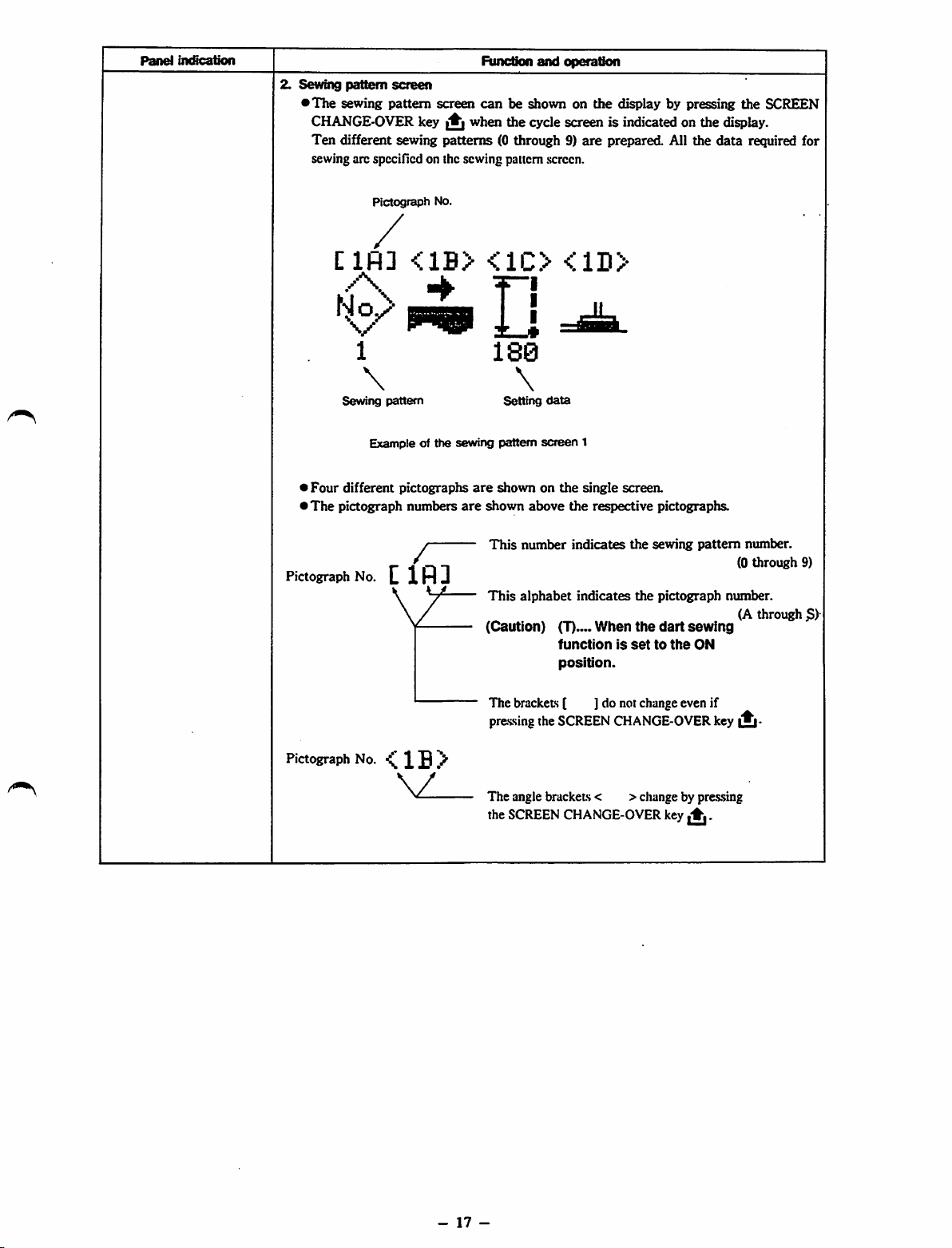
2.
Sewing
pattern
screen
•
The
sewing pattern screen
CHANGE-OVER
Ten
different sewing
sewing arc spccillcd on the sewing pattern screen.
key^when
patterns
can
be shown on the display by pressing the SCREEN
the
(0 through 9}
and
operation
cycle
screenisindicatedonthe
are
prepared
All the
display.
data
required for
Clfl]
Sewing
>
Four
different
*The
pictograph
Pictograph
Pictograph
1
\
pattern
Exampleofthe
pictographs
numbers
No.
Clfll
No.
<1B>
/"
sewing
are
are
<1C>
u
180
\
Setting
pattern
shownonthe
shown
above
This
number
This
alphabet
(Caution)
<1D>
data
screen
(T)
function
position.
1
single
the
respective
indicates
indicates
When
screen.
the
the
the
is
settothe
pictographs.
sewing
pattern
pictograph
dart
sewing
ON
number.
(0
through
number.
(A
through
9)
S)
Pictograph
No.^1B>
The brackets [ ] do not change even if
pressing the SCREEN CHANGE-OVER key
The angle brackets < >change by pressing
the
SCREEN
CHANGE-OVER
key
^.
-
17
-
Panel
From the library of: Superior Sewing Machine & Supply LLC
Imfication
Function
b
iMJ
and
operation
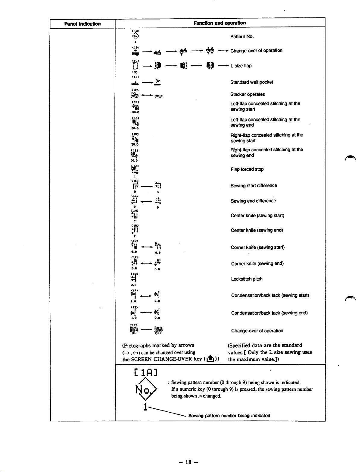
Pattern
No.
18«
<I0>
tin
30.0
Kg
30.0
CIH]
'/I
30.0
30.0
tyj
•-T
r?
a
^h'
a
titi]
ni!
Y
^ Change-over of operation
» L-size flap
Standard
Stacker
Left-flap
sewing
Left-flap
sewing
Right-flap
sewing
welt
pocket
operates
concealed
stitching at
start
concealed
stitchingatthe
end
concealedstitchingat the
start
the
Right-flap concealed stitching at the
sewing
end
Flap forced
Sewing
Sewing
I
Center
stop
start
difference
end
difference
knife (sewing
start)
7
<10>
a.a
II
0.0
ctoi
2.0
<IR>
1.0
<1S>
<1T>
Oi'i*
UUO«
oil
(Pictographs
(-^,
the
can be changedover asing
SCREEN
[IR]
/\
0.0
0.0
2.0
*•!
2.0
Il»Tll
markedbyarrows
CHANGE-OVER
Sewing pattern number (0 through 9) being shown is indicated.
If a numeric key (0 through 9) is
being shown is changed.
key
(A
Center
knife (sewing
Corner knife (sewing start)
Comer
knife (sewing end)
Lockstitch pitch
Condensation/back tack (sewing start)
Condensation/back tack (sewing end)
Change-overof operation
(Specified
data
are
values.[ Only the L
))
the
maximum
pre.s.sed,
value.])
the .sewingpattern number
end)
the
size
standard
sewing
uses
Sewing
pattern
-
18
-
number
being
indicated
Panel
From the library of: Superior Sewing Machine & Supply LLC
indication
Function
and
operation
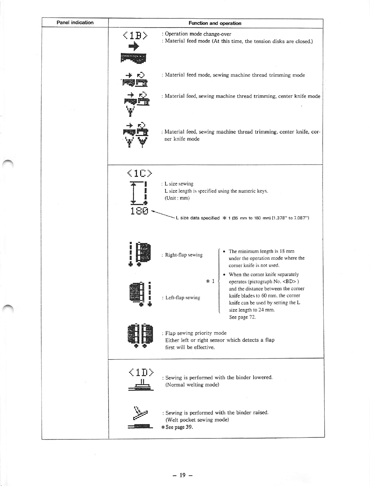
<1B>
L :
y V
<1C>
X—*
180-
:
Operation
Material
;
Material
:
Material
Material
ner
L size sewing
L size length is specified using the numeric keys.
I
(Unit:
knife
L
mm)
size
feed mode,
feed,
feed, sewing
mode
mode
change-over
feed mode (At
sewing
sewing
data
specified
this
time,
the
machine
machine
machine
thread
thread
* 1 (35 mm to 100 mm)
tension
thread
trimming,
trimming,
disks
are
closed.)
trimming
(1.378"to7.087")
center
center
mode
knife
knife,
mode
cor
<1D>
Right-flap .sewing
Left-flap .sewing
Flap
sewing priority
Either left or right
first
willbeeffective.
: Sewing is performed
(Normal
welting
: Sewing is performed
(Welt
pocket
sewing
*See
page 39.
mode
sensor
mode)
The minimum length is 18 mm
under the operation mode where the
comer
knifeisnot
When the corner knife separately
used.
operates (piciograph No.
and
the
distance
knife
bladesto60
knife can be u.sed by .setting the L
size length to 24 mm.
See page 72.
which
detectsaflap
with
the
binder
with
the
binder
mode)
between
mm.
lowered.
raised.
<BD>)
the
the
comer
corner
Panel
From the library of: Superior Sewing Machine & Supply LLC
incQcation
Function
and
operation
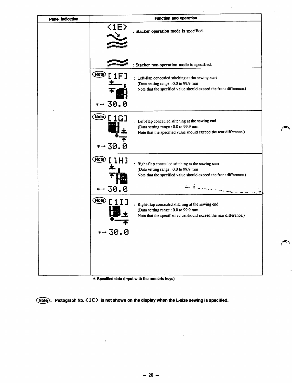
<1E>
30
• 0
±
*-30.0
(@)[iH]
n
*-*
30-
:
Stacker
:
Stacker
I
operation mode is specified.
non-operation
Left-flapconcealedstitchingat the
(Data setting range :0.0 to 99.9 mm
Notethat thespecified value
Left-flap
(Data
Note
Right-flap concealed stitching at the sewing .start
(Data .settingrange : 0.0 to 99.9 mm
Note that the .specifiedvalue should exceed the front difference.)
concealed
.setting
range: 0.0 to 99.9 mm
thatthe
.specified
mode
stitching
value
is specified.
.sewing
.start
.should
exceedthefrontdifference.)
atthe
sewing
end
should
exceed
therear
0
difference.)
(jiote):
Plctograph
No.
<1C> is
C@)
♦
-30.0
4: Specified
not
[11]
data
shown
Right-flap concealed stitching at the .sewingend
(Data .settingrange :0.0 to 99.9 mm
Note that the .specifiedvalue .shouldexceed the rear difference.)
(Input with
onthe
the
numeric
display
when
keys)
the
L-size
sewingisspecified.
-
20
-
Panel
From the library of: Superior Sewing Machine & Supply LLC
indication
C
IJ]
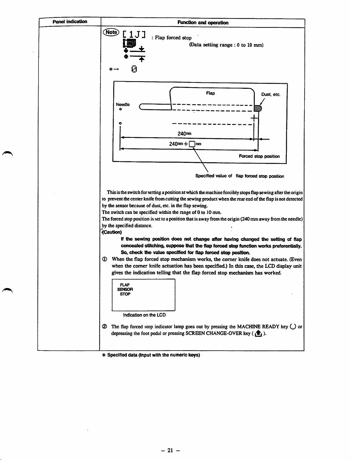
Flap
forced
Function
stop
and
operation
(Data setting range : 0 to 10 nun)
Rap
Needte
o
240"*"
240'w-i-|
Thisis theswitchfor
to prevent thecenter knife fromcuning thesewing product when therear end of the flap is notdetected
by the sensor
The
switch can be specified within the rangeof0 to 10 mm.
The forced stoppo.sition is .settoa position that isaway from the origin (240 mmaway fromtheneedle)
by the specified distance.
<(Caution)
I
When
when
gives
becau.se
If
the
concealed
So,
check
the
the
the
.setting
apositionat whichthemachineforciblystopsflapsevnngafterthe origin
of dast, etc. in the flap sewing.
sewing
flap
comer
indication telling
position
sfttctdng,
the
value specified for flap forced
forced
knife
does
stippose
stop
mechanism
actuation
that
not
has
the
ttiat
Itnm
Specified
change
the
works,
been
flap
value
after
flap
forced
stop
the
comer
specified.) In
forced
stop
of flap forced
having
stop
posftkm.
mechanism
>
Dust,
etc.
/
Forced
stop
position
stop
position
changed
function worlcs preferentially.
knife
this
case,
the
does
not
the
LCD display unit
has
worked.
setting of flap
actuate.
(Even
The
depres.sing
*
Specified
Indicationonthe
flap
forced
the
data
(Input with
LCD
stop
indicator
foot
pedalorpressing
the
-
lamp
numeric
21
-
goesout by
SCREEN
keys)
pressing
CHANGE-OVER
the
MACHINE
key
(A
READY
)•
keyO
oi"

Panel
From the library of: Superior Sewing Machine & Supply LLC
indication
Function
and
operation
<1K>
I
IT
I 1
0
^1!
6
<1L>
i
±«
B
qp—*
0
I
l±
0
C
IM]
±i
I
^ll
7
Sewingstart
hand
(Data setting range: 0 to 20 mm)
(When this data is set to zero (0), the left-hand .seamand right-hand seam
are made in parallel with each other.)
Sewing startdifference (The left-hand
hand
(Data .setting
(When this data is .setto zero (0), the left-hand
are made in parallel with each other.)
Sewing end difference (The left-hand side seam is .shorterthan the right-
hand
(Data .settingrange: 0 to 20 nun)
(When this data is .setto zero (0), the left-hand seam and right-hand seam
are made in parallel with each other.)
Sewing end difference (The right-hand side .seamis shorter than the left-
hand
(Data .setting range : 0 to 20 mm)
(When this data is .setto zero (0), the left-hand seam and right-hand seam
are made in parallel with each other.)
Center knife actuating po.sitionon the .sewingstart
(Data .setting
[The center knife .starts operating at the position that is away from the
shorter .seamby the .specifieddistance.]
side
side
side
side
difiference
one.)
one.)
range:
one.)
one.)
range:
(Theright-handside seam is shorter than the left-
.side
seam is shorter than the right-
0 to 20 mm)
seam
and right-hand seam
0 to
1.5
mm)
Z
•±-ii
T**
^ Specified
IN]
<10)
t'i
^iV!
0.0
-lY!
0.0
data
Centerknife actuating
(Data .setting
I
[The center knife .starts operating at the position that is away from the
shorter.seam by the specified distance.]
Recommendable data .setting
Coriierknife
(Data .settingrange : 0.0 to 10.0 mm)
l'
[The
.setting
(Refer to page 30)
The comer knifeactuates at the
.specified distance.]
Comerknife
(Data .settingrange : 0.0 to 10.0 mm)
[The
setting
(Refer to page 30)
Thecomer
specified distance.]
(Input wittt tlie numeric keys)
po.sition
range:
0 to 15 mm)
range:
actuating
valueiseffectiveonly
actuating
valueiseffectiveonly
knife
po.sition
position on the
actuates
at the
on the
7 to 15 mm
onthe
when
position
when
position
.sewing
end
.sewing
.start
thecomerknife
insidethe
sewing
start
thecomerknife
outside
the
actuates
.shorter
actuates
shorter
separately.
.seam
by the
separately.
seamby the
-
22
-
Panel
From the library of: Superior Sewing Machine & Supply LLC
indication
Function
and
operation
<1P>
ili
0.0
I I I
fi
±.4,
0.0
C
IQ]
±_i
"T"!
2.0
<1R>
1.0
2.0
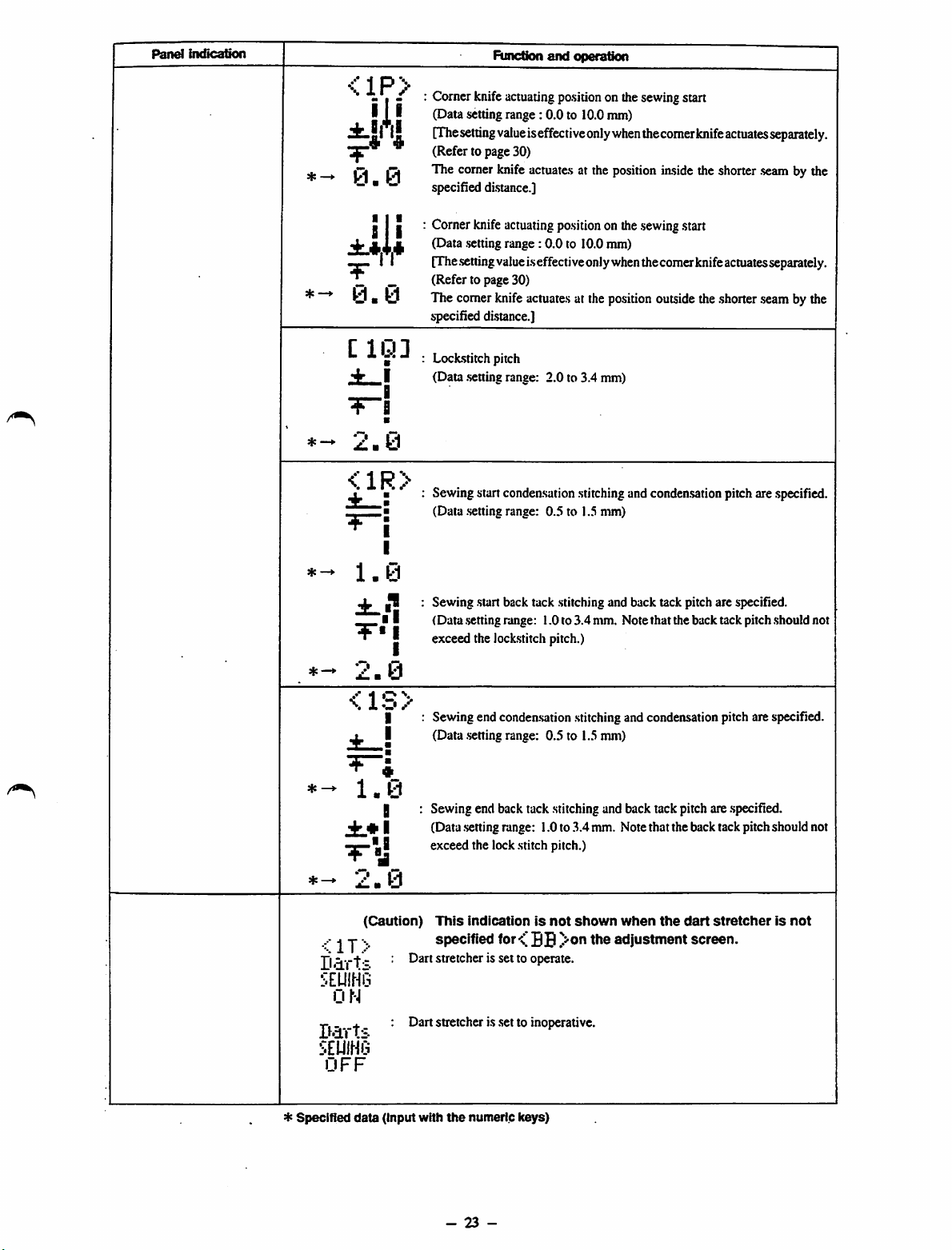
Comer knife actuatingpositionon thesewingstart
(Datasettingrange: 0.0 to 10.0nun)
[The
setting
value
iseffectiveonly
(Refer to page 30)
The comer knife
specified di.stance.]
Cornerknife
I
(Data .setting
[The
.setting
(Refer to page 30)
The comerknife
specified distance.]
Loclcstitchpitch
(Data
I
•
•
I
I
.setting
Sewingstart condeasation
(Data .settingrange: 0.5 to 1.5 mm)
Sewing start back tack .stitchingand back tack pitch are specified.
(Data .settingrange: 1.0to 3.4mm. Note that the back tack pitch should not
exceed the lockstitch pitch.)
actuate.s
actuating
range:
value
range: 2.0 to 3.4 mm)
po.sition
0.0 to 10.0 mm)
i.s
effectiveonlywhenthecomerknifeactuatesseparately.
actuate.s
when
thecomer
at the position iaside the shorter
onthe
.sewing
at the
position
.stitching
andcondensationpitch are specified.
start
outside
knife
actuates
theshorter
separately.
.seam
by the
.seam
bythe
*
Specified
Darts
smm
ON
Darts
smm
OFF
<1S>
1.0
jfc.* I
^•-1
2.0
(Caution)
j
data
I
H
(input
Sewing endcondeasation
(Data
.setting
range: 0.5 to 1.5mm)
Sewing end back tack stitching and back tack pitch are .specified.
(Data settingrange: 1.0to
exceed the lockstitch pitch.)
This
indicationisnot
specified
Dart stretcher is set to operate.
Dart stretcher is .setto inoperative.
with
the
for
numeric
keys)
BB
.stitching
.3.4
shown
and condensationpitch are specified.
mm. Notethat theback tackpitch should not
when
the
dart
stretcherisnot
adjustment
screen.
-
23
-
Panel
From the library of: Superior Sewing Machine & Supply LLC
indication
Function
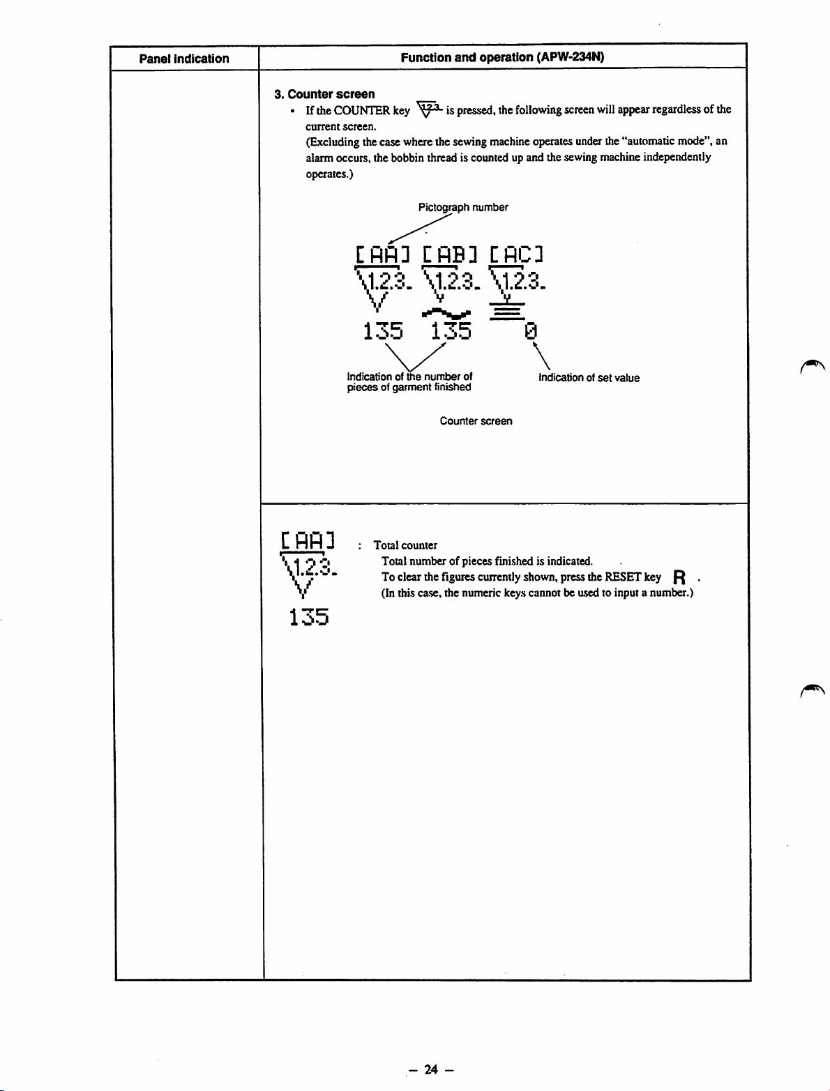
3.
Counter
• If the
screen
COUNTER
current
screen.
(Excludingthecasewherethesewing
alarm occurs, the bobbin thread is counted up and the sewing machine independently
operates.)
key is
and
operation (APW-234N)
pressed,
the
following
machine
operatesunderthe"automaticmode",an
screen
willappearregardless of the
C
flfl
\1.2.3.
V
[flfl]
\1.2.3.
V ^
135
Indicationofthe
piecesofgarment
3
Total
counter
Total number of pieces finished is indicated.
To
clear
(In this ca.se,the numeric keys cannot be used to input a number.)
Pictograph
CflB3
\1.2.3.
135
i-j
number
finished
Counter
the
figures
number
of
screen
currently
CflC3
\1.2.3.
0
\
shown,
indicationofset
press
the
value
RESET
key
^
135
-
24
-
Panel
From the library of: Superior Sewing Machine & Supply LLC
indication
Function
and
operation
[RB]
CflC]
\1.2.3.
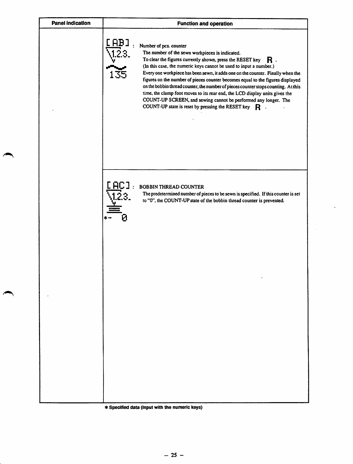
Number of pcs. counter
The numberof the sewnworkpieces is indicated.
To
clear
the
figures
cuirently
(In thi.sca.se,the numeric keys cannot be used to input a number.)
Everyone workpiece hasbeensewn, itadds one onthe counter. Finallywhen the
figureson the numberofpiecescounter becomesequal to thefiguresdisplayed
onthebobbinthreadcounter,the numberofpiecescounterstopscounting. Atthis
time,theclampfoot movesto its rear end, the LCDdisplay unitsgivesthe
COUNT-UP
COUNT-UP
BOBBIN
Thepredetermined numberofpieces to besewn isspecified. If thiscounter is set
to "0", the COUNT-UP state of the bobbin thread counter is prevented.
SCREEN,and sewingcannot be performedany longer. The
stateisresetbypressing
THREAD
COUNTER
shown,
press
the
the
RESET
RESET
key
key
R .
R .
*-
0
*
Specified
data
(Input with
the
-
numeric
25
-
keys)
Panel
From the library of: Superior Sewing Machine & Supply LLC
Indication
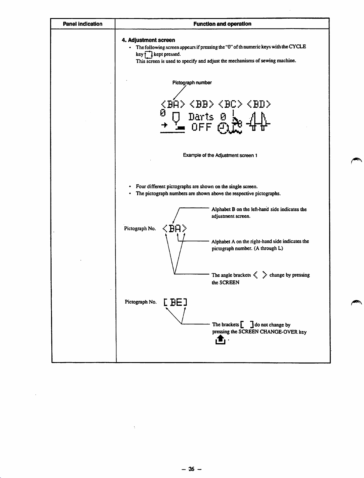
4.
Adjustment
• The
following
key kept pressed.
Thisscreenis usedto
screen
screen
Function
appearsifpressing
specify
andadjustthe
and
operation
the"0"ofth
mechanisms
numeric
ofsewing
keys
withthe
machine.
CYCLE
Pictograph
. / .
®
1?
• Four different pictographs are shown on the single screen.
• The pictograph numbers are shown above the respective pictographs.
y
/
w
Pictograph
No. /•'
\
\ /
number
....
<.BU>
D?rU
UFF
Example of the Adjustment
0k M
Alphabet
adjustment
Alphabet
pictograph
Bonthe
Aonthe
<%BD>
tTt
screen
1
left-hand
screen.
right-hand
number.(Athrough
sideindicates the
side
indicates
L)
the
Pictograph
No.tBED
\ 1
•••
Theangle
the
The
pressing the SCREEN CHANGE-OVER key
brackets
SCREEN
brackets
y*
^ ]donot
changebypressing
change
by
•ii
-
26
-
 Loading...