


O P E R A T O R ’ S M A N U A L
FERTILIZER SPREADERS
SS1023B
SS1036B
SS1067B
SS2036B
SS2067B
Manual 5BP960376B
Date 05/19/2011

SAFETY
Take note! This safety alert symbol found throughout this manual is used to call your attention to instructions involving your personal safety and the safety of others. Failure to follow these instructions can result in injury or death.
This symbol means:
ATTENTION!
BECOME ALERT!
YOUR SAFETY IS INVOLVED!
Signal Words
Note the use of the signal words DANGER, WARNING and CAUTION with the safety messages. The appropriate signal words for each have been selected using the following guidelines:
DANGER: Indicates an imminently hazardous situation that, if not avoided, will result in death or serious injury.
WARNING: Indicates a potentially hazardous situation that, if not avoided, could result in death or serious injury, and includes hazards that are exposed when guards are removed. It may also be used to alert against unsafe practices.
CAUTION: Indicates a potentially hazardous situation that, if not avoided, may result in minor or moderate injury.
INDEX
1 |
- GENERAL INFORMATION |
4 |
|
|
1.01 |
- General |
4 |
|
1.02 |
- Model and Serial Number ID |
4 |
|
1.03 |
- Assembly Instructions for Model SS1023B |
5 |
|
1.04 |
- Assembly Instructions for Models SS1036B & SS2036B |
6 |
|
1.05 |
- Assembly Instructions for Models SS1067B & SS2067B |
8 |
2 |
- SAFETY PRECAUTIONS |
11 |
|
|
2.01 |
- Preparation |
11 |
|
2.02 |
- Starting and Stopping |
11 |
|
2.03 |
- Messages and Signs |
12 |
3 |
- OPERATION |
14 |
|
|
3.01 |
- Operational Safety |
14 |
|
3.02 |
- Set Up |
15 |
|
3.03 |
- Pre-Operational Check |
15 |
|
3.04 |
- Attaching to the Tractor |
16 |
|
3.05 |
- Start Up |
17 |
|
3.06 |
- Operating Techniques |
17 |
|
3.07 |
- Uneven Terrain |
20 |
4 |
- MAINTENANCE |
21 |
|
|
4.01 |
- Maintenance Safety |
21 |
|
4.02 |
- Service |
22 |
|
4.03 |
- Driveline |
22 |
|
4.04 |
- Transport |
23 |
5 |
- REPAIR PROCEDURES |
26 |
|
|
5.01 |
- Suggested Spare Parts |
26 |
|
5.02 |
- Storage |
26 |
6 |
- TROUBLESHOOTING |
27 |
|
7 |
- PRE-DELIVERY CHECKLIST |
28 |
|
PARTS MANUAL |
31 |
||
INDEX |
3 |
FRONTIER |

FERTILIZER SPREADERS |
OPERATOR’S MANUAL |
1 - GENERAL INFORMATION
Thank you and congratulations for having chosen our implement. Your new fertilizer spreader is a technologically advanced machine constructed of high quality sturdy components that will fulfill your working expectations. Read this manual carefully. It will instruct you on how to operate and service your fertilizer spreader safely and correctly. Failure to do so could result in personal injury and/or equipment damage.
1.01 - General
The implement described in this manual is to be used with tractors with PTO at 540 rpm and clockwise rotation.
CAUTION: Always ensure that the coupling of the implement with the tractor is done at the same PTO speed and direction of rotation. Do not operate this implement at a PTO speed or direction of rotation other than that shown on the implement. Serious damage can occur to the machine and/or the operator.
CAUTION: Unless otherwise specified, all hardware is metric. Use only metric tools on metric hardware. Other tools that do not fit properly can slip and cause injury.
CAUTION: Right hand and left hand sides of the implement are determined by facing in the direction the implement will travel when going forward (see fig. 6).
Warranty coverage is provided by John Deere according to the terms of the Agricultural/Commercial & Consumer Equipment Warranty Statement. Carefully read the warranty statement on the back of your original purchase order for details on coverage and limitations of this warranty.
Your Authorized Company Dealer has genuine parts in stock. Only these approved replacement parts should be used.
1.02 - Model and Serial Number ID
Attached to the hopper is an ID plate showing the model and the serial number. Record your implement model and serial number in the space provided below. Your dealer needs this information to give you prompt, efficient service when you order parts.
GENERAL INFORMATION |
4 |
FRONTIER |

FERTILIZER SPREADERS |
OPERATOR’S MANUAL |
1.03 - Assembly Instructions for Model SS1023B
CAUTION: Stand clear of bands when cutting as they could be under sufficient tension to cause them to fly loose. Take care in removing bands and wire. They often have extremely sharp edges and cut very easily.
NOTE: Assembly will be easier if all parts are loosely assembled before tightening the hardware. All hardware needed for assembly will be found in the hardware bag or on the machine.
Each unit is shipped with a hardware bag that consists of the following:
Description |
Model SS1023B Qty. |
Spreader disc (#11, fig. 2) |
1 |
Mobile shutter (#10, fig. 2) |
1 |
Stirrer (#8, fig. 2) |
1 |
Guard (#4, fig. 2) |
1 |
Flow control assembly (#5, fig. 2) |
1 |
Driveline |
1 |
Hardware bag contains the following: |
|
Bushing cat.0/1 for tractor arms (5BP0014710); serial #XF...287132 & below only |
2 |
Threaded bushing (5BP501622B) |
1 |
Bolt CR M08-1.25x25 C4.6 Z (5BP501663B) |
3 |
Bolt HH M08-1.25x16 C8.8 Z F (5BP0046454) |
2 |
Nut HH M30-2.00 C6 Z TN (5BP501651B) |
1 |
Nut HH M08-1.25 C6 Z TK (5BP0001806) |
8 |
Washer flat Ø8 (5BP0015230) |
4 |
Washer fender Ø8 (5BP0014514) |
3 |
Hairpin cotter Ø5 (5BP0041291) |
1 |
To assemble the spreader do the following:
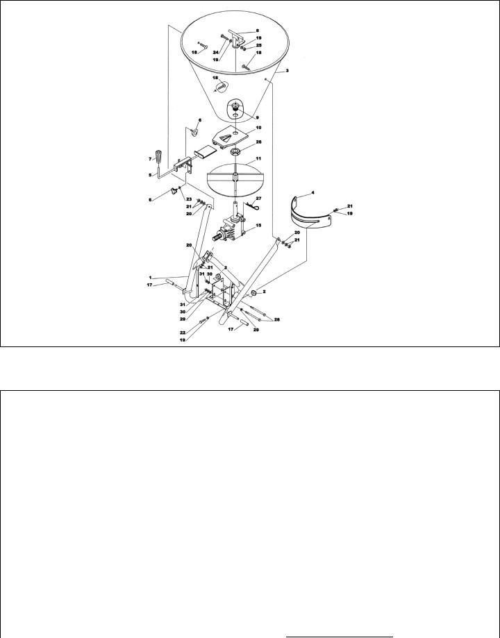
1.Attach spreader disc (see #11, fig. 2) to output shaft of gearbox securing it with the hairpin cotter
(see #27, fig. 2).
2.Install guard (see #4, fig. 2) with scale label facing up to the brackets on the spreader frame.
Attach it to the frame using two M8x16 bolts (see #22, fig. 2), four Ø8 flat washers (see #19, fig. 2) and two M8 nuts (see #21, fig. 2).
3.Insert threaded bushing (see #9, fig. 2) through hopper bottom (see #3, fig. 2). Attach mobile shutter (see #10, fig. 2) to threaded bushing and secure with nut (see #26, fig. 2).
4.Slide hopper and onto the output shaft of the gearbox. Secure hopper to frame using three M8x25 carriage bolts (see #18, fig. 2), three Ø8 fender washers (see #20, fig. 2), and six M8 hex nuts
(see #21, fig. 2).
5.Install flow control assembly (see #5, fig. 2) into slot in mobile shutter at the bottom of the hopper.
6.Secure location of the shutter lever by tightening the two knobs (see #6, fig. 2).
7.Install the stirrer (see #8, fig. 2) using M8x35 hex bolt (see #24, fig. 2), two Ø8 flat washers (see #19, fig. 2), and one M8 elastic stop nut (see #25, fig. 2) that are already bolted to the stirrer.
8.Tighten all hardware.
9.Install driveline and ensure it has at least 2” from bottoming out in its shortest working position and has the minimum 6” overlap in its longest working position. Refer to Section 4.031 of this manual, if it is determined that the driveline is too long and needs to be shortened. Contact your local dealer if it is determined that the driveline is too short for your tractor.
1 |
See Section 4.03 - Driveline, for instructions on how to determine correct driveline length and procedures for |
||
|
|
|
|
shortening the driveline. |
|
|
|
GENERAL INFORMATION |
5 |
FRONTIER |
|
FERTILIZER SPREADERS |
OPERATOR’S MANUAL |
Fig. 2 - Model SS1023 assembly.
1.04 - Assembly Instructions for Models SS1036B & SS2036B
Each unit is shipped with a hardware bag that consists of the following:
Description |
Model SS1036B Qty. |
Model SS2036B Qty. |
Spreader disc (#21, fig. 3) |
1 |
1 |
Shutter assembly |
1 |
1 |
Protection (#5, fig. 3) |
1 |
1 |
Lever (#16, fig. 3) |
1 |
1 |
Scaled rod assembly (#18, fig. 3) |
1 |
1 |
Stationary stirrer (#20, fig. 3) |
1 |
1 |
Protection (#4, fig. 3) |
1 |
1 |
Driveline |
1 |
1 |
Hardware bag contains the following: |
|
|
Attachment plate (5BP0014338) (#6, fig. 3) |
1 |
- |
Attachment plate (5BP0014635) (#6, fig. 3) |
- |
1 |
Bushing cat.0/1 for tractor arms (5BP0014710) |
2 |
2 |
Bolt CR M08-1.25x20 C4.6 Z (5BP0084289) |
3 |
2 |
Bolt CR M08-1.25x25 C4.6 Z (5BP501663B) |
3 |
- |
Bolt CR M08-1.25x35 C4.6 Z (5BP0014619) |
- |
3 |
Bolt HH M08-1.25x16 C8.8 Z F (5BP0046454) |
1 |
1 |
Bolt HH M08-1.25x20 C8.8 Z F (5BP0015012) |
2 |
2 |
Nut HH M08-1.25 C6 Z MD (5BP0046545) |
6 |
5 |
Nut HH M08-1.25 C6 Z TK (5BP0001806) |
6 |
6 |
Washer lock Ø8 (5BP0003144) |
3 |
2 |
Washer flat Ø8 (5BP0015230) |
7 |
6 |
Washer fender Ø8 (5BP0014514) |
3 |
3 |
Washer fender Ø10 (5BP0030157) |
2 |
2 |
Hairpin cotter Ø5 (5BP0041291) |
1 |
1 |
GENERAL INFORMATION |
6 |
FRONTIER |

FERTILIZER SPREADERS |
OPERATOR’S MANUAL |
CAUTION: Stand clear of bands when cutting as they could be under sufficient tension to cause them to fly loose. Take care in removing bands and wire. They often have extremely sharp edges and cut very easily.
NOTE: Assembly will be easier if all parts are loosely assembled before tightening the hardware. All hardware needed for assembly will be found in the hardware bag or on the machine.
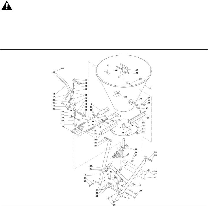
Fig. 3 - Model SS1036B & SS2036B assembly.
To assemble the spreader do the following:
1.Attach spreader disc (see #21, fig. 3) to the output shaft of the gearbox using hairpin cotter (see #45, fig. 3).
2.Locate scaled rod assembly (see #18, fig. 3) in hardware bag. Install scaled rod to main frame using M8x30 bolt (see #29, fig. 3), Ø8 lock washer (see #40, fig. 3), M8 hex nut (see #34, fig. 3) that are already installed on the scaled rod assembly.
3.Install protection (see #4, fig. 3) onto spreader frame using two M8x20 hex bolts (see #26, fig. 3), four Ø8 flat washers (see #38, fig. 3), and two M8 hex nuts (see #34, fig. 3).
4.Slide hopper onto the output shaft of the gearbox. Secure hopper to frame using three M8x25 carriage bolts on model SS1036 or M8x35 on model SS2036 (see #25, fig. 3), three Ø8 fender washers (see #39, fig. 3), and six M8 hex nuts (see #33, fig. 3).
GENERAL INFORMATION |
7 |
FRONTIER |

FERTILIZER SPREADERS |
OPERATOR’S MANUAL |
5.Install the stationary stirrer (see #20, fig. 3) using M8x45 hex bolt (see #31, fig. 3), two Ø8 flat washers (see #38, fig. 3), and one M8 elastic stop nut (see #36, fig. 3) that are already bolted to the stirrer.
6.Install protection (see #5, fig. 3) using two M8x20 carriage bolts (see #28, fig. 3), two Ø10 fender washers (see #42, fig. 3), two Ø8 lock washers (see #40, fig. 3) and secure with two M8 hex nuts
(see #34, fig. 3). Install attachment plate (see #6, fig. 3) on protection using M8x16 hex bolt (see #27, fig. 3), two Ø8 flat washers (see #38, fig. 3) and secure with M8 hex nut (see #34, fig. 3), then install it to the hopper using M8x20 carriage bolt on model SS1036 or M8x25 on model
SS2036 (see #28, fig. 3), on model SS2036 use bolt already installed on hopper, and secure with
Ø8 flat washer (see #38, fig. 3), Ø8 lock washer (see #40, fig. 3) and a M8 hex bolt (see #34, fig. 3).
7.Install shutter assembly found in the hardware bag by sliding shutters (see #7 & #8, fig. 3) into the slots at bottom of the hopper.
8.Assemble shutter guide plate (see #11, fig. 3) to lever bracket (see #12, fig. 3), which is already installed on the frame using M8x30 hex bolt (see #29, fig. 3), Ø8 lock washer (see #40, fig. 3), and M8 hex nut (see #34, fig. 3).
9.Install lever (see #16, fig. 3) to lever bracket using one M8x20 hex bolt (see #26, fig. 3) which is shipped installed on the lever. Secure bolt with M8 hex nut (see #34, fig. 3).
10.Tighten all hardware.
11.Install driveline and ensure it has at least 2” from bottoming out in its shortest working position and has the minimum 6” overlap in its longest working position. Refer to Section 4.032 of this manual, if it is determined that the driveline is too long and needs to be shortened. Contact your local dealer if it is determined that the driveline is too short for your tractor.
1.05 - Assembly Instructions for Models SS1067B & SS2067B
Each unit is shipped with a hardware bag that consists of the following:
Description |
Model SS1067B Qty. |
Model SS2067B Qty. |
Lever (#14, fig. 4) |
1 |
1 |
Hitch lever (#15, fig. 4) |
1 |
1 |
Scaled rod (#17, fig. 4) |
1 |
1 |
Shutter assembly (#9, fig. 4) |
1 |
1 |
Protection (#4, fig. 4) |
1 |
1 |
Protection (#1, fig. 5) |
1 |
1 |
Spreader wings (#20, fig. 4) |
4 |
4 |
Stationary stirrer (#21, fig. 4) |
1 |
1 |
Driveline |
1 |
1 |
Hardware bag contains the following: |
|
|
Attachment plate (5BP0014338) (#2, fig. 5) |
1 |
- |
Attachment plate (5BP0014339) (#2, fig. 5) |
- |
1 |
Bolt CR M12-1.75x30 C4.6 Z (5BP0051073) |
3 |
- |
Bolt CR M12-1.75x40 C8.8 Z (5BP0044115) |
- |
3 |
Bolt CR M08-1.25x20 C4.6 Z (5BP0084289) |
1 |
- |
Bolt HH M08-1.25x16 C8.8 Z F (5BP0046454) |
3 |
3 |
Bolt HH M08-1.25x20 C8.8 Z F (5BP0015012) |
2 |
2 |
Bolt HH M06-1.00x16 C8.8 Z F (5BP0036319) |
8 |
8 |
Nut HH M12-1.75 C6 Z MD (5BP0001106) |
6 |
6 |
Nut HH M08-1.25 C6 Z MD (5BP0046545) |
6 |
5 |
Nut HH M06-1.00 C6 Z TK (5BP501603B) |
8 |
8 |
Washer lock Ø6 (5BP0046536) |
8 |
8 |
Washer lock Ø8 (5BP0003144) |
1 |
- |
Washer flat Ø8 (5BP0015230) |
11 |
10 |
Washer flat Ø14 (5BP0091435) |
3 |
3 |
2 |
See Section 4.03 - Driveline, for instructions on how to determine correct driveline length and procedures for |
||
|
|
|
|
shortening the driveline. |
|
|
|
GENERAL INFORMATION |
8 |
FRONTIER |
|
FERTILIZER SPREADERS |
OPERATOR’S MANUAL |
CAUTION: Stand clear of bands when cutting as they could be under sufficient tension to cause them to fly loose. Take care in removing bands and wire. They often have extremely sharp edges and cut very easily.
NOTE: Assembly will be easier if all parts are loosely assembled before tightening the hardware. All hardware needed for assembly will be found in the hardware bag or on the machine.
Fig. 4 - Models SS1067B & SS2067B assembly.
To assemble the spreader do the following:
1.Attach four spreader wings (see #20, fig. 4) to the spreader disc (see #19, fig. 4) with eight M6x16 hex bolts (see #36, fig. 4), Ø6 lock washers (see #37, fig. 4) and M6 hex nuts (see #38, fig. 4).
2.Locate scaled rod assembly (see #17, fig. 4) in hardware bag. Install scaled rod to main frame using M8x30 hex bolt (see #29, fig. 4), Ø8 lock washer (see #30, fig. 4) and M8 hex nut (see #28, fig. 4) that are already installed on the scaled rod assembly.
3.Install protection (see #4, fig. 4) on spreader frame using two M8x20 hex bolts (see #26, fig. 4), two Ø8 flat washers (see #27, fig. 4) and two M8 hex nuts (see #28, fig. 4).
4.Slide hopper (see #3, fig. 4) onto the output shaft of the gearbox.
GENERAL INFORMATION |
9 |
FRONTIER |
FERTILIZER SPREADERS |
OPERATOR’S MANUAL |
5.Secure hopper to frame using three M12x30 carriage bolts on model SS1067B or M12x40 on model SS2067B (see #23, fig. 4), three Ø14 flat washers (see #24, fig. 4), and six M12 hex nuts
(see #25 fig. 4).
6.Install stationary stirrer (see #21, fig. 4) using M8x45 bolt (see #39, fig. 4), two Ø8 flat washers
(see #27, fig. 4), and M8 elastic stop nut (see #40, fig. 4) that are already bolted to the stirrer.
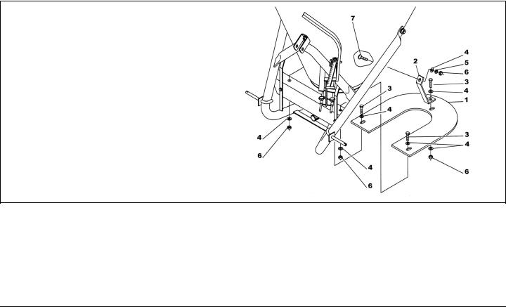
7.This step only applies to units with serial #BC…304870 and above. Install spreader disc shield (see #1, fig. 5) using three M8x16 hex bolts (see #3, fig. 5), six Ø8 flat washers (see #4, fig. 5), one Ø8 lock washer (see #5, fig. 5), and three M8 hex nuts (see #6, fig. 5). Install M8x20 carriage bolt (see #7, fig. 5) on SS1067B or M8x25 on SS2067B through hopper and into attachment plate (see #2, fig. 5). On model SS2067B use bolt already installed on hopper.
8.Install shutter assembly, found in hardware bag, by sliding shutters (see #5 & #6, fig. 4) into the slots at the bottom of the hopper.
9.Assemble shutter guide plate (see #9, fig. 4) to lever bracket (see #10, fig. 4), which is already installed on the frame, using M8x30 hex bolt (see #29, fig. 4), Ø8 lock washer (see #30, fig. 4), and M8 hex nut (see #28, fig. 4).
10.This step only applies to units with serial #BC…304870 and above. Attach hitch lever (see #15, fig. 4) to lever bracket (see #10, fig. 4) by loosening M8x20 hex bolt (see #26, fig. 4) which is shipped already installed onto hitch lever. Secure bolt with M8 hex nut (see #28, fig. 4).
11.Install lever (see #14, fig. 4) to hitch lever using M8x20 hex bolt (see #26, fig. 4) and M8 hex nut (see #28, fig. 4) which is shipped already installed on the lever.
12.Tighten all hardware.
13.Install driveline and ensure it has at least 2” from bottoming out in its shortest working position and has the minimum 6” overlap in its longest working position. Refer to Section 4.033 of this manual, if it is determined that the driveline is too long and needs to be shortened. Contact your local dealer if it is determined that the driveline is too short for your tractor.
Fig. 5 - Models SS1067B & SS2067B shield assembly. (serial #BC...304870 and above)
3 |
See Section 4.03 - Driveline, for instructions on how to determine correct driveline length and procedures for |
||
|
|
|
|
shortening the driveline. |
|
|
|
GENERAL INFORMATION |
10 |
FRONTIER |
|
FERTILIZER SPREADERS |
OPERATOR’S MANUAL |
2 - SAFETY PRECAUTIONS
Safety is the primary concern in the design and manufacture of our products. Unfortunately our efforts to provide safe equipment can be wiped out by a single careless act of an operator.
In addition to the design and configuration of equipment, hazard control and accident prevention are dependent upon the awareness, concern, prudence and proper training of personnel involved in the operation, transport, maintenance and storage of equipment.
It is the operator’s responsibility to read and understand all safety and operating instructions in the manual and to follow these.
Allow only properly trained personnel to operate the fertilizer spreader. Working with unfamiliar equipment can lead to careless injuries. Read this manual, and the manual for your tractor, before assembly or operation, to acquaint yourself with the machines. It is the spreader owner’s responsibility, if this machine is used by any person other than yourself, is loaned or rented, to make certain that the operator, prior to operating, reads and understands the operator’s manuals and is instructed in safe and proper use.
2.01- Preparation
1.Before operating equipment read and understand the operator’s manual and the safety signs (see fig. 6).
2.Thoroughly inspect the implement before initial operation to assure that all packaging materials, i.e., wires, bands, and tape have been removed.
3.Personal protection equipment including hard hat, safety glasses, safety shoes, and gloves are recommended during assembly, installation, operation, adjustment, maintaining and/or repairing the implement.
4.Operate the fertilizer spreader only with a tractor equipped with an approved Roll-Over-Protective-System (ROPS). Always wear your seat belt. Serious injury or even death could result from falling off the tractor.
5.Clear area of stones, branches or other debris that might be thrown, causing injury or damage.
6.Operate only in daylight or good artificial light.
7.Ensure fertilizer spreader is properly mounted, adjusted and in good operating condition.
8.Ensure that all safety shielding and safety signs are properly installed and in good condition.
9.Chemicals may cause eye, skin or breathing problems. Always wear a face mask, gloves and goggles when filling hopper.
10.Before loading the fertilizer in the hopper read carefully the instructions printed on the fertilizer canvas bag concerning the precautions to be taken in case of toxicity or corrosivity of the product. Before loading switch off the engine and remove the ignition key.
11.Load hopper with product only after the spreader has been properly attached to the tractor.
2.02- Starting and Stopping
1.Be sure that no one is near the machine prior to engaging or while the machine is working.
2.Be sure the tractor is in “Neutral” before starting engine.
SAFETY PRECAUTIONS |
11 |
FRONTIER |
FERTILIZER SPREADERS |
OPERATOR’S MANUAL |
3.The operating power is supplied from tractor PTO. Refer to your tractor manual for PTO engagement and disengagement instructions. Always operate PTO at 540 rpm. Know how to stop the tractor and machine quickly in case of an emergency.
4.When engaging PTO, the engine rpm should always be low. Once engaged and ready to start operating, raise PTO speed to 540 rpm and maintain throughout operation.
5.Check the tractor master shield over the PTO stub shaft. Make sure it is in good condition and fastened securely to the tractor. Purchase a new shield if old shield is damaged or missing.
6.After striking an obstacle, disengage the PTO, shut the tractor down and thoroughly inspect for damage before restarting.
7.To park the vehicle safely, stop vehicle on a level surface (not on a slope), disengage PTO, engage the parking brake, stop the engine, remove the key, and wait for engine and all moving parts to stop before leaving the operator’s seat.
8.Stay clear of rotating drivelines. Entanglement in rotating driveline can cause serious injury or death. Wear close fitting clothing. Stop the engine and be sure PTO driveline is stopped before getting near it.
2.03- Messages and Signs
1.Read and adhere to all safety and operating decals on this machine (see fig. 6).
2.Before dismounting tractor: Stop engine, set brake and remove the key of unattended equipment.
3.Keep away from rotating parts and driveline.
4.Keep guards and shields in place and in good condition.
5.Do not use with bystanders in area.
6.Allow no riders on tractor or fertilizer spreader.
7.Allow moving parts to stop before repair.
8.Securely support fertilizer spreader before working underneath.
Additional warning and operating decals are available at no extra charge. Please specify model and serial number when ordering.
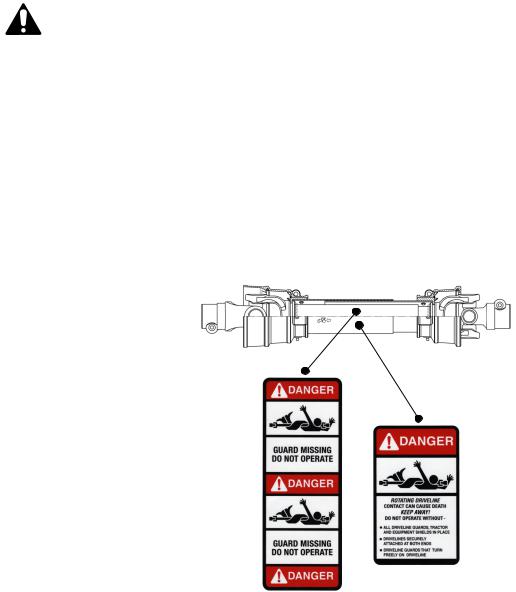
Fig. 6 - Safety decals - driveline; replace immediately if damaged.
outer shield
outer tube
SAFETY PRECAUTIONS |
12 |
FRONTIER |

FERTILIZER SPREADERS |
OPERATOR’S MANUAL |
Safety decals - implement; replace immediately if damaged.
right side |
left side |
SAFETY PRECAUTIONS |
13 |
FRONTIER |

FERTILIZER SPREADERS |
OPERATOR’S MANUAL |
3 - OPERATION
The fertilizer spreader is versatile and ideal for granular or powdered fertilizers, seed and sand. It may also be used as a salt spreader for snow or ice covered roads during winter months. Our spreaders are designed for tractors from 16 to 30 PTO HP with a category 1 three point hitch.
Spreaders can be used for broadcast spreading or may be used to spread prevalently to the left or to the right with a simple adjustment.
The wide range of hopper capacities and numerous spread adjustments make our fertilizer spreaders ideal for use on farms, athletic fields, municipalities and many other commercial or residential applications.
3.01 - Operational Safety
CAUTION: Our spreaders are designed considering safety as the most important target and are the safest available in today’s market. Unfortunately, human carelessness can override the safety features built into our machines. Injury prevention and work safety, aside from the features on our spreaders, are very much due to the responsible use of the equipment. It must always be operated prudently following with great care, the safety instructions laid out in this manual.
1.The use of this equipment is subject to certain hazards which cannot be prevented by mechanical means or product design. All operators of this equipment must read and understand this entire manual, paying particular attention to safety and operating instructions, prior to using.
2.Do not operate the tractor and spreader when you are tired, sick or when using medication.
3.This spreader is designed for use only on tractors with 540 rpm power take off.
4.Only properly trained people should operate this machine.
5.Accidents are most likely to occur with machines that are loaned or rented to someone who has not read the operator’s manual and is not familiar with a spreader.
6.Always stop the tractor, set brake, shut off the tractor engine, remove the ignition key, and allow spreader moving parts to come to a complete stop before dismounting tractor. Never leave equipment unattended with the tractor running.
7.Never place hands or feet into hopper with tractor engine running or before you are sure all motion has stopped. Stay clear of all moving parts.
8.Never allow any person inside the hopper for any reason. Serious injury or death can result from someone becoming entangled in the agitator.
9.Do not allow riders on the spreader or tractor at any time. There is no safe place for riders.
10.Never allow anyone within 50 yards of the spreader while the PTO is engaged. Product thrown from the spreader can cause serious injury or death.
11.Before backing up, look behind carefully.
12.Install and secure all guards and shields before starting or operating.
13.Keep hands, feet, hair and clothing away from moving parts.
14.Never operate tractor and spreader under trees with low hanging limbs. Operators can be knocked off the tractor and then run over.
15.Stop spreader immediately upon striking an obstruction. Turn engine off, remove key, inspect and repair any damage before resuming operation.
OPERATION |
14 |
FRONTIER |

FERTILIZER SPREADERS |
OPERATOR’S MANUAL |
16.Stay alert for holes, rocks and roots in the terrain and other hidden hazards. Keep away from drop-offs.
17.Use extreme care and maintain minimum ground speed when transporting on hillside, over rough ground and when operating close to ditches or fences. Be careful when turning sharp corners.
18.Reduce speed on slopes and sharp turns to minimize tipping or loss of control. Be careful when changing directions on slopes. Do not start or stop suddenly on slopes. Avoid operation on steep slopes.
19.Inspect the entire machine periodically4. Look for loose fasteners, worn or broken parts, and leaky or loose fittings.
20.Pass diagonally through sharp dips and avoid sharp drops to prevent “hanging up” tractor and spreader.
21.Avoid sudden starts and stops while traveling up or downhill.
22.Always operate down slopes; never across the face. Avoid operation on steep slopes. Slow down on sharp turns and slopes to prevent tipping and/or loss of control.
23.All remote control devices (cables, ropes, rods, flexible lines, etc.) should be positioned in a way to prevent maneuvers which could lead to accidents or damages.
24.Chemicals may cause eye, skin or breathing problems. Always wear a face mask, gloves and goggles when filling hopper.
25.Before loading the fertilizer in the hopper read carefully the instructions printed on the fertilizer canvas bag concerning the precautions to be taken in case of toxicity or corrosivity of the product. Before loading switch off the engine and remove the ignition key.
26.Load hopper with product only after the spreader has been properly attached to the tractor.
3.02 - Set Up
Notice to dealer: Pre-Delivery set up and service including lubrication are the responsibility of the authorized dealer. It is up to him to assure that the machine is in perfect condition and ready to be used. It is his responsibility to ensure that the customer is aware of all safety aspects and operational procedures for the spreader. He must also fill out the Pre-Delivery Checklist5 prior to delivering the spreader.
CAUTION: Stand clear of bands when cutting as they could be under sufficient tension to cause them to fly loose. Take care in removing bands and wire, as they often have extremely sharp edges and cut very easy.
3.03 - Pre-Operational Check
Check each of the following, carefully, prior to engaging the equipment:
1.No wrappings or foreign objects are around the spreader.
2.All hardware is tight.
3.All safety shields and guards are in place and tightly attached.
4.No people or animals are in the work area.
DANGER: Shut off the tractor and remove the key before making adjustments, servicing or cleaning the machine.
4
5
See Chapter 4 - Maintenance.
See Chapter 7 - Pre-Delivery Checklist.
OPERATION |
15 |
FRONTIER |
FERTILIZER SPREADERS |
OPERATOR’S MANUAL |
3.04 - Attaching to the Tractor
Unit may be used on tractors ranging from 16 to 30 HP equipped with a standard rear PTO and category 1 three point hitch6. Never use this spreader with tractors over 30 HP.
DANGER: Do not allow anyone to stand between spreader and tractor while attaching implement.
WARNING: Never attempt to attach the implement to the tractor or make an adjustment to it without first turning the tractor off.
CAUTION: Check the tractor PTO rpm to ensure it is set at 540 rpm and turns clockwise.
CAUTION: Be sure the tractor tire pressure is correct. It is important to strictly follow the safety guidelines and instructions laid out in the tractor manual.
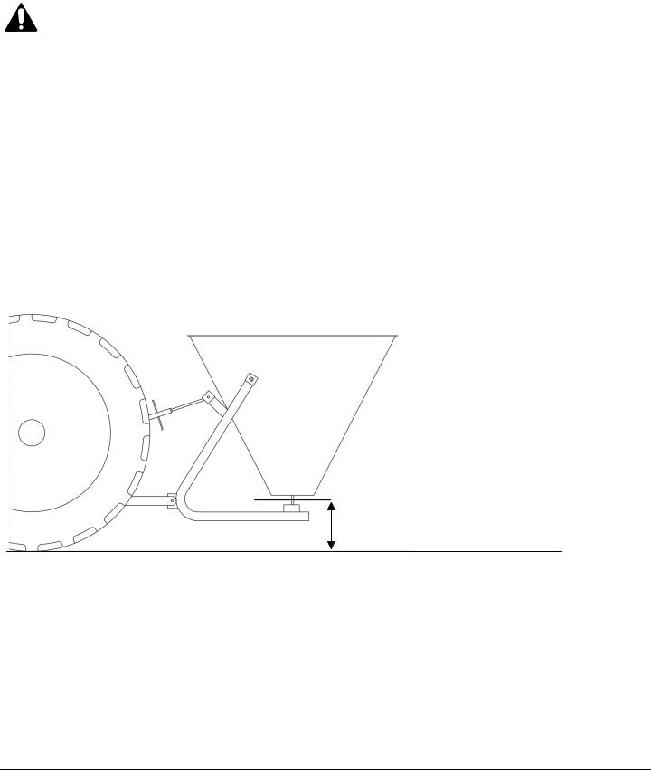
Fig. 7 - Hopper spreading adjustment.
28" to 32"
Ground level
To attach the implement to the tractor do the following:
Back the tractor up to the implement in order to slip the tractor hitch arms over the hitch pins bolted to the frame. Turn off the tractor engine and engage the park brake. Secure the two tractor hitch arms to the implement with lynch pins. Tighten the tractor arms side movement with either the sway chains or blocks to limit side swing.
Connect the top link, locking it in place with the top hitch pin. Adjust it so the implement is as near parallel to the ground as possible with the spreading disc at a distance 28” to 32” above ground level
(see fig. 7).
Install the end of the driveline to the spreader and the opposite end to the tractor PTO. Be sure each end is connected securely with either the locking pin or bolt and nut. Connect the driveline shielding chains to the tractor and to the implement to prevent the protective shielding from rotating during
6 |
See Table 2, page 24. |
|
|
|
|
|
|
OPERATION |
16 |
FRONTIER |
|

FERTILIZER SPREADERS |
OPERATOR’S MANUAL |
operation. If it was necessary to remove the PTO shielding to do any of the above operations, do not forget to replace it.
3.05 - Start Up
CAUTION: Load hopper with product only after the spreader has been properly attached to the tractor.
WARNING: Chemicals may cause eye, skin or breathing problems. Always wear a face mask, gloves and goggles when filling hopper. Refer to chemical manufacturer’s label for specific safety information.
Before starting to use, never forget that the operator is responsible for the following:
1.Safe and correct driving of the tractor and spreader.
2.To learn precise, safe operating procedures for both the tractor and the spreader.
3.To ensure all maintenance and lubrication has been performed on the spreader.
4.To have read and understood all safety aspects for the spreader in the operator’s manual.
5.To have read and understood all safety decals on the spreader.
6.Checking the tractor tires for the proper pressure in accordance with the tractor operator’s manual.
7.Checking that all safety shields are on the machine and securely in place.
8.Making sure the proper attire is worn. Avoiding loose fitting clothing which can become entangled.
Wearing sturdy, tough-soled work shoes and protective equipment for eyes, hands, ears and head. Never operate tractor or implements in bare feet, sandals or sneakers.
9.Ensuring proper lighting is available, sunlight or good artificial lighting.
WARNING: Use a tractor with a cab and appropriate filters on the ventilation system or wear a breathing mask capable of filtering toxic powders to prevent inhalation of product.
Prior to start working do the following:
1.Make sure there are no obstructions.
2.Run machine under a no-load condition for a short while to assure that everything is functioning properly.
3.Adjust all settings for the desired quantity distribution and spread pattern.
4.Shift the transmission to a slow speed gear and start forward, increase the ground speed by shifting upward until the desired speed is obtained. Do not use in reverse unless absolutely necessary and only after careful observation of the area behind the spreader.
5.Ballast may need to be added to tractor to maintain steering control.
3.06- Operating Techniques
WARNING: Before adjusting the spreader or filling the hopper, be sure the tractor PTO is not engaged, the tractor is shut off, and the key is removed from the tractor ignition.
OPERATION |
17 |
FRONTIER |
 Loading...