

Page 1
Operation, Safety, Service
and Maintenance Manual
ANSI / CSA
Keep this manual with the machine at all times.
1-877-254-3876 LIFTPOD by JLG
1-877-2-LIFTPOD www.liftpod.com
LiftPod Model
FS80
P/N - 1001070451
February 11, 2009
FS.book Page 1 Wednesday, February 11, 2009 11:54 AM
Page 2

This page intentionally left blank.
FS.book Page 2 Wednesday, February 11, 2009 11:54 AM
Page 3

FOREWORD
1-877-254-3876 LIFTPOD by JLG 1001070451
1-877-2-LIFTPOD www.liftpod.com a
FOREWORD
This manual is a very important tool! Keep it with the machine at all times.
The purpose of this manual is to provide owners, users, operators, lessors, and lessees with the precautions and operating procedures essential for the safe and proper machine operation for its intended purpose.
Due to continuous product improvements, JLG Industries, Inc. (JLG) reserves the right to make specification changes
without prior notification. Contact JLG for updated information.
Page 4
FOREWORD
1001070451 LIFTPOD by JLG 1-877-254-3876
b www.liftpod.com 1-877-2-LIFTPOD
SAFETY ALERT SYMBOLS AND SAFETY SIGNAL WORDS
INDICATES AN IMMINENTLY HAZARDOUS SITUATION. IF NOT
AVOIDED, WILL
RESULT IN SERIOUS INJURY OR DEATH. THIS DECAL
WILL HAVE A RED BACKGROUND.
INDICATES A POTENTIALITY HAZARDOUS SITUATION. IF NOT
AVOIDED, COULD
RESULT IN SERIOUS INJURY OR DEATH. THIS
DECAL WILL HAVE AN ORANGE BACKGROUND.
INDICATES A POTENTIALITY HAZARDOUS SITUATION. IF NOT
AVOIDED, MAY
RESULT IN MINOR OR MODERATE INJURY. IT MAY
ALSO ALERT AGAINST UNSAFE PRACTICES. THIS DECAL WILL HAVE A
YELLOW BACKGROUND.
This is the Safety Alert Symbol. It is used to alert you to the potential personal
injury hazards. Obey all safety messages that follow this symbol to avoid possible
injury or death
FS.book Page b Wednesday, February 11, 2009 11:54 AM
Page 5

FOREWORD
1-877-254-3876 LIFTPOD by JLG 1001070451
1-877-2-LIFTPOD www.liftpod.com c
THIS PRODUCT MUST COMPLY WITH ALL SAFETY RELATED BULLETINS. CONTACT JLG OR THE LOCAL AUTHORIZED JLG REPRESENTATIVE FOR INFORMATION REGARDING SAFETY RELATED BULLETINS
WHICH MAY HAVE BEEN ISSUED FOR THIS PRODUCT.
NOTICE
JLG MUST BE NOTIFIED IMMEDIATELY IN ALL INSTANCES WHERE JLG
PRODUCTS HAVE BEEN INVOLVED IN AN ACCIDENT INVOLVING
BODILY INJURY OR DEATH OF PERSONNEL OR WHEN SUBSTANTIAL
DAMAGE HAS OCCURRED TO PERSONAL PROPERTY OR THE JLG
PRODUCT.
Contact:
Product Safety and Reliability Department
JLG Industries, Inc.
13244 Fountainhead Plaza
Hagerstown, MD 21742
USA
In USA:
Toll Free: 877-JLG-SAFE (877-554-7233)
Outside USA:
Phone: 717-485-6591
E-mail: ProductSafety@JLG.com
or your local JLG office
(see addresses on manual’s rear cover)
For:
• Accident reporting
• Product safety publications
• Current owner updates
• Questions regarding
product safety
• Standards and regulations
compliance information
• Questions regarding special product applications
• Questions regarding product modifications
Page 6

FOREWORD
1001070451 LIFTPOD by JLG 1-877-254-3876
d www.liftpod.com 1-877-2-LIFTPOD
REVISION LOG
Original Issue of Manual . . . . . . . . . . . . . . . . . . . May 14, 2008
Revised . . . . . . . . . . . . . . . . . . . . . . . . . . . . . . . . June 04, 2008
Revised . . . . . . . . . . . . . . . . . . . . . . . . . . . September 25, 2008
Revised . . . . . . . . . . . . . . . . . . . . . . . . . . . September 29, 2008
Revised . . . . . . . . . . . . . . . . . . . . . . . . . . . . February 11, 2009
FS.book Page d Wednesday, February 11, 2009 11:54 AM
Page 7

TABLE OF CONTENTS
SECTION - PARAGRAPH, SUBJECT PAGE SECTION - PARAGRAPH, SUBJECT PAGE
1-877-254-3876 LIFTPOD by JLG 1001070451
1-877-2-LIFTPOD www.liftpod.com i
SECTION - 1 - SAFETY PRECAUTIONS
1.1 GENERAL . . . . . . . . . . . . . . . . . . . . . . . . . . . . . . . . 1-1
1.2 PRE-OPERATION . . . . . . . . . . . . . . . . . . . . . . . . . . 1-2
Operator Training and Knowledge . . . . . . . . . . . 1-2
Workplace Inspection . . . . . . . . . . . . . . . . . . . . . 1-2
Machine Inspection. . . . . . . . . . . . . . . . . . . . . . . 1-2
1.3 OPERATION . . . . . . . . . . . . . . . . . . . . . . . . . . . . . . 1-3
General . . . . . . . . . . . . . . . . . . . . . . . . . . . . . . . . 1-3
Trip and Fall Hazard . . . . . . . . . . . . . . . . . . . . . . 1-4
Electrocution Hazard . . . . . . . . . . . . . . . . . . . . . 1-5
Tipping Hazards . . . . . . . . . . . . . . . . . . . . . . . . . 1-6
Crushing and Collision Hazards . . . . . . . . . . . . . 1-7
1.4 MOVING, LIFTING AND REPOSITIONING. . . . . . . 1-8
General . . . . . . . . . . . . . . . . . . . . . . . . . . . . . . . . 1-8
Additional Safety Information . . . . . . . . . . . . . . . 1-8
SECTION - 2 - PREPARATION AND INSPECTION
2.1 PERSONNEL TRAINING. . . . . . . . . . . . . . . . . . . . . 2-1
Operator Training . . . . . . . . . . . . . . . . . . . . . . . . 2-1
Training Supervision . . . . . . . . . . . . . . . . . . . . . . 2-1
Operator Responsibility . . . . . . . . . . . . . . . . . . . 2-1
2.2 PREPARATION, INSPECTION, AND
MAINTENANCE . . . . . . . . . . . . . . . . . . . . . . . . . . 2-2
Pre-Start Inspection . . . . . . . . . . . . . . . . . . . . . . 2-4
2.3 DAILY WALK-AROUND INSPECTION . . . . . . . . . . 2-4
Walk-Around Inspection Components . . . . . . . . 2-5
Tool Tray Pre-Start Inspection. . . . . . . . . . . . . . . 2-9
2.4 FUNCTION CHECK. . . . . . . . . . . . . . . . . . . . . . . . 2-10
Function Check Items . . . . . . . . . . . . . . . . . . . . 2-10
SECTION - 3 - MACHINE OPERATION
3.1 GENERAL . . . . . . . . . . . . . . . . . . . . . . . . . . . . . . . . 3-1
3.2 MACHINE DESCRIPTION . . . . . . . . . . . . . . . . . . . . 3-1
Detailed Description . . . . . . . . . . . . . . . . . . . . . . 3-2
Platform Configuration. . . . . . . . . . . . . . . . . . . . . 3-3
Mast/Carriage Components . . . . . . . . . . . . . . . . 3-3
3.3 MACHINE OPERATION. . . . . . . . . . . . . . . . . . . . . . 3-4
General . . . . . . . . . . . . . . . . . . . . . . . . . . . . . . . . 3-4
Getting Started. . . . . . . . . . . . . . . . . . . . . . . . . . . 3-4
Assembly of the Machine . . . . . . . . . . . . . . . . . . 3-4
Disassembly of the Machine . . . . . . . . . . . . . . . . 3-9
3.4 POWERPACK (OPTIONAL EQUIPMENT). . . . . . . 3-10
Battery Charging Operation. . . . . . . . . . . . . . . . 3-10
Battery Charge Status Lights. . . . . . . . . . . . . . . 3-10
Charging the Batteries Using the Fast Charge
Station . . . . . . . . . . . . . . . . . . . . . . . . . . . . . . . . 3-11
Fast Charge Indicator Light Guide . . . . . . . . . . 3-11
Power Supply Cord . . . . . . . . . . . . . . . . . . . . . . 3-12
3.5 OPERATION . . . . . . . . . . . . . . . . . . . . . . . . . . . . . 3-12
Cordless Drill . . . . . . . . . . . . . . . . . . . . . . . . . . . 3-12
Page 8

TABLE OF CONTENTS
SECTION - PARAGRAPH, SUBJECT PAGE SECTION - PARAGRAPH, SUBJECT PAGE
1001070451 LIFTPOD by JLG 1-877-254-3876
ii www.liftpod.com 1-877-2-LIFTPOD
Powerpack Control Console (Optional
Equipment) . . . . . . . . . . . . . . . . . . . . . . . . . . . . 3-13
Elevating . . . . . . . . . . . . . . . . . . . . . . . . . . . . . . 3-14
Descending . . . . . . . . . . . . . . . . . . . . . . . . . . . . 3-16
Powerpack Emergency Stop/Shutdown Button 3-16
Unpowered Descent . . . . . . . . . . . . . . . . . . . . . 3-17
3.6 TRANSPORT AND MANEUVERING (MOVING) . . 3-17
General . . . . . . . . . . . . . . . . . . . . . . . . . . . . . . . 3-17
Fully Assembled Maneuvering . . . . . . . . . . . . . 3-18
Disassembled Maneuvering . . . . . . . . . . . . . . . 3-19
Parking and Storage . . . . . . . . . . . . . . . . . . . . . 3-20
Vehicle Transport. . . . . . . . . . . . . . . . . . . . . . . . 3-20
SECTION - 4 - EMERGENCY PROCEDURES
4.1 GENERAL INFORMATION . . . . . . . . . . . . . . . . . . . 4-1
Manual Descent Crank . . . . . . . . . . . . . . . . . . . . 4-1
Discharged Battery . . . . . . . . . . . . . . . . . . . . . . . 4-1
Operator Unable to Control Machine . . . . . . . . . 4-2
Platform Caught Overhead . . . . . . . . . . . . . . . . . 4-3
Rope Failure. . . . . . . . . . . . . . . . . . . . . . . . . . . . . 4-4
4.2 INCIDENT NOTIFICATION . . . . . . . . . . . . . . . . . . . 4-5
SECTION - 5 - GENERAL SPECIFICATIONS
5.1 INTRODUCTION . . . . . . . . . . . . . . . . . . . . . . . . . . . 5-1
5.2 DECAL INSTALLATION. . . . . . . . . . . . . . . . . . . . . . 5-1
5.3 GENERAL SPECIFICATIONS . . . . . . . . . . . . . . . . . 5-8
Machine Specifications (assembled) . . . . . . . . . . 5-8
Optional Powerpack Electrical Specifications . . .5-9
Platform Data . . . . . . . . . . . . . . . . . . . . . . . . . . . 5-10
Machine Component Weights . . . . . . . . . . . . . . 5-11
Serial Number Locations . . . . . . . . . . . . . . . . . . 5-11
SECTION - 6 - SERVICE AND MAINTENANCE
6.1 INTRODUCTION - MAINTENANCE SAFETY
PRECAUTIONS . . . . . . . . . . . . . . . . . . . . . . . . . . . 6-1
General . . . . . . . . . . . . . . . . . . . . . . . . . . . . . . . . . 6-1
Maintenance Safety . . . . . . . . . . . . . . . . . . . . . . . 6-2
6.2 MACHINE PREPARATION, INSPECTION AND
MAINTENANCE . . . . . . . . . . . . . . . . . . . . . . . . . . . 6-3
General . . . . . . . . . . . . . . . . . . . . . . . . . . . . . . . . . 6-3
Preparation, Inspection, and Maintenance . . . . . 6-3
Pre-Start Inspection . . . . . . . . . . . . . . . . . . . . . . . 6-3
Frequent and Pre-Delivery Inspection . . . . . . . . .6-3
Annual Machine Inspection . . . . . . . . . . . . . . . . . 6-3
5 Year Machine Inspection & Rope
Replacement . . . . . . . . . . . . . . . . . . . . . . . . . . . .6-4
Preventive Maintenance . . . . . . . . . . . . . . . . . . . . 6-4
6.3 PREVENTIVE MAINTENANCE AND INSPECTION
SCHEDULE . . . . . . . . . . . . . . . . . . . . . . . . . . . . . . 6-4
6.4 SERVICING AND MAINTENANCE GUIDELINES . 6-8
General . . . . . . . . . . . . . . . . . . . . . . . . . . . . . . . . . 6-8
FS.book Page ii Wednesday, February 11, 2009 11:54 AM
Page 9

TABLE OF CONTENTS
SECTION - PARAGRAPH, SUBJECT PAGE SECTION - PARAGRAPH, SUBJECT PAGE
1-877-254-3876 LIFTPOD by JLG 1001070451
1-877-2-LIFTPOD www.liftpod.com iii
Safety and Workmanship . . . . . . . . . . . . . . . . . . 6-8
Cleanliness . . . . . . . . . . . . . . . . . . . . . . . . . . . . . 6-8
Component Disassembly and Reassembly . . . . 6-8
6.5 REPLACEMENT KITS OVERVIEW . . . . . . . . . . . . . 6-9
6.6 DECAL REPLACEMENT . . . . . . . . . . . . . . . . . . . . 6-11
6.7 MAST ROPE INSPECTION PROCEDURE . . . . . 6-12
1. Rope Wear . . . . . . . . . . . . . . . . . . . . . . . . . . 6-12
2. Rope Misaligned . . . . . . . . . . . . . . . . . . . . . . 6-12
3. Rope Loose . . . . . . . . . . . . . . . . . . . . . . . . . . 6-13
SECTION - 7 - TROUBLESHOOTING
7.1 GENERAL . . . . . . . . . . . . . . . . . . . . . . . . . . . . . . . . 7-1
Troubleshooting Information . . . . . . . . . . . . . . . 7-1
LIST OF FIGURES
1-1. Read your manual . . . . . . . . . . . . . . . . . . . . . . . . . 1-2
2-1. Daily Walk-Around Inspection (Sheet 1 of 2) . . . . . 2-5
2-2. Examples of cracks . . . . . . . . . . . . . . . . . . . . . . . . 2-5
2-3. Daily Walk-Around Inspection (Sheet 2 of 2) . . . . . 2-6
2-4. Examples of new, acceptable and unacceptable
ropes . . . . . . . . . . . . . . . . . . . . . . . . . . . . . . . . . . . 2-7
2-5. Ropes retained in mast cap . . . . . . . . . . . . . . . . . . 2-7
2-6. Rope anchor points . . . . . . . . . . . . . . . . . . . . . . . . 2-7
2-7. Platform latch shown engaged . . . . . . . . . . . . . . . 2-8
2-8. Location of manual descent crank . . . . . . . . . . . . . 2-8
2-9. Tool tray installation . . . . . . . . . . . . . . . . . . . . . . . . 2-9
3-1. Main components . . . . . . . . . . . . . . . . . . . . . . . . . . 3-1
3-2. Base frame component description . . . . . . . . . . . . 3-2
3-3. Platform component description . . . . . . . . . . . . . . 3-3
3-4. Mast/carriage component description . . . . . . . . . . 3-3
3-5. Carriage/mast to base mounting . . . . . . . . . . . . . . 3-5
3-6. Detail view of level bubble . . . . . . . . . . . . . . . . . . . 3-5
3-7. Attaching the platform to the carriage . . . . . . . . . . 3-6
3-8. Platform attachment checks . . . . . . . . . . . . . . . . . . 3-6
3-9. Cordless drill installation . . . . . . . . . . . . . . . . . . . . . 3-7
3-10. Powerpack positioned and latched into place . . . . 3-8
3-11. Tool tray load restriction . . . . . . . . . . . . . . . . . . . . . 3-9
3-12. Battery charging plug and tester . . . . . . . . . . . . . 3-10
3-13. Charge status lights . . . . . . . . . . . . . . . . . . . . . . . 3-10
3-14. Removing the battery from the powerpack . . . . . 3-11
3-15. Recharge dock operations and indicators . . . . . . 3-11
3-16. Typical cordless drill interface devices . . . . . . . . . 3-12
3-17. Powerpack control console . . . . . . . . . . . . . . . . . 3-13
3-18. Cordless drill elevation . . . . . . . . . . . . . . . . . . . . . 3-14
3-19. Detail view of direction selector . . . . . . . . . . . . . . 3-15
3-20. Detail view of enable & speed triggers . . . . . . . . . 3-15
3-21. Emergency stop button operation . . . . . . . . . . . . 3-16
3-22. Activate the handle to extend the swivel castor . . 3-18
Page 10

TABLE OF CONTENTS
SECTION - PARAGRAPH, SUBJECT PAGE SECTION - PARAGRAPH, SUBJECT PAGE
1001070451 LIFTPOD by JLG 1-877-254-3876
iv www.liftpod.com 1-877-2-LIFTPOD
3-23. Maneuvering when tilted back . . . . . . . . . . . . . . . 3-18
3-24. Mast/carriage handle . . . . . . . . . . . . . . . . . . . . . . 3-19
3-25. Moving base through a door . . . . . . . . . . . . . . . . 3-20
4-1. Manual descent crank operation from inside
platform . . . . . . . . . . . . . . . . . . . . . . . . . . . . . . . . . 4-2
4-2. Manual descent crank operation from outside
platform . . . . . . . . . . . . . . . . . . . . . . . . . . . . . . . . . 4-2
4-3. Releasing the drive interlock using the lanyard . . . 4-3
5-1. Base Decal Installation - ANSI . . . . . . . . . . . . . . . . 5-4
5-2. Carriage/Mast Decal Installation - ANSI . . . . . . . . . 5-5
5-3. Platform Decal Installation - ANSI . . . . . . . . . . . . . . 5-6
5-4. Powerpack Decal Installation - ANSI . . . . . . . . . . . 5-7
6-1. Replacement Kits . . . . . . . . . . . . . . . . . . . . . . . . . . 6-9
6-2. Drum view through inspection window . . . . . . . . 6-12
6-3. Rope alignment through carriage. . . . . . . . . . . . . 6-13
6-4. Loose rope being re-tensioned. . . . . . . . . . . . . . . 6-13
LIST OF TABLES
1-1 Minimum Approach Distances (M.A.D.) . . . . . . . . . 1-5
2-1 Inspection and Maintenance Table. . . . . . . . . . . . . 2-3
5-1 Decal Descriptions. . . . . . . . . . . . . . . . . . . . . . . . . . 5-3
5-2 Machine Specifications (assembled) . . . . . . . . . . . 5-8
5-3 Optional Powerpack Electrical Specifications . . . . 5-9
5-4 Platform Data . . . . . . . . . . . . . . . . . . . . . . . . . . . . .5-10
5-5 Machine Component Weights . . . . . . . . . . . . . . . .5-11
6-1 Preventative Maintenance & Inspection Schedule . 6-7
7-1 Troubleshooting. . . . . . . . . . . . . . . . . . . . . . . . . . . . 7-4
FS.book Page iv Wednesday, February 11, 2009 11:54 AM
Page 11

SECTION 1 - SAFETY PRECAUTIONS
1-877-254-3876 LIFTPOD by JLG 1001070451
1-877-2-LIFTPOD www.liftpod.com 1-1
SECTION 1. SAFETY PRECAUTIONS
1.1 GENERAL
This section outlines the necessary precautions for proper and
safe machine usage and maintenance. For proper machine use, it
is mandatory that a daily routine is established based on the content of this manual. A maintenance program, using the information
provided in this manual must also be established by a qualified
person and must be followed to ensure that the machine is safe to
operate.
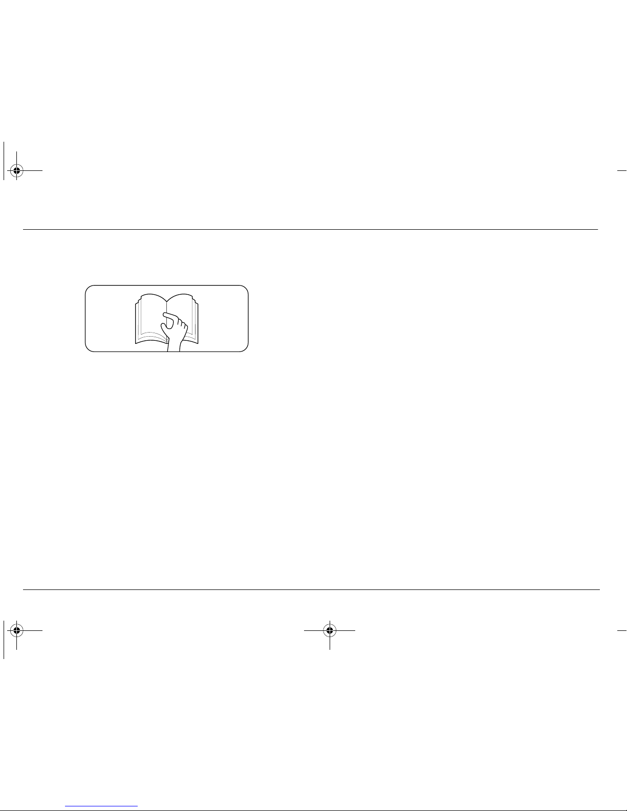
Before operation, the operator shall:
1. Read and understand the manufacturer’s (remanufacturer’s) operating instruction(s) and user’s safety rules
or have them explained.
2. Understand all labels, warnings and instructions displayed on the aerial platform or have them explained.
3. Ensure all occupants of the aerial platform wear appropriate personal protection equipment (PPE) for the conditions, including the environment in which the aerial
platform will be operated.
If there are any questions with regard to safety, training, inspection, maintenance, application, and operation, please contact JLG.
FAILURE TO COMPLY WITH THE SAFETY PRECAUTIONS LISTED IN THIS
MANUAL COULD RESULT IN MACHINE DAMAGE, PROPERTY DAMAGE,
PERSONAL INJURY OR DEATH.
Page 12
SECTION 1 - SAFETY PRECAUTIONS
1001070451 LIFTPOD by JLG 1-877-254-3876
1-2 www.liftpod.com 1-877-2-LIFTPOD
1.2 PRE-OPERATION
Operator Training and Knowledge
• Do not operate this machine until complete training is performed by authorised persons.
• Only authorised and qualified personnel can operate the
machine.
• Read, understand, and obey all DANGERS, WARNINGS,
CAUTIONS, and operating instructions on the machine
and in this manual.
• Use the machine in a manner which is within the scope of
its intended application set by JLG.
• All operating personnel must be familiar with the emergency controls and emergency operation of the machine
as specified in this manual.
• Read, understand, and obey all applicable employer,
local, and governmental regulations as they pertain to
operation of the machine.
Workplace Inspection
• The operator is to take safety measures to avoid all hazards in the work area prior to machine operation.
• Do not operate or raise the platform while on trucks, trailers, railway cars, floating vessels, scaffolds or other equipment unless approved in writing by JLG.
• This machine can be operated in temperatures of 0°C to
40°C (32°F to 104°F). Consult JLG for operation outside
this range. Machine performance may vary from published specification in very hot or cold conditions.
Machine Inspection
• Before machine operation, perform inspections and functional checks. Refer to Section 2 of this manual for further
instructions.
• Do not operate this machine until it has been serviced and
maintained according to requirements specified in accordance with this manual.
Figure 1-1. Read your manual
FS.book Page 2 Wednesday, February 11, 2009 11:54 AM
Page 13

SECTION 1 - SAFETY PRECAUTIONS
1-877-254-3876 LIFTPOD by JLG 1001070451
1-877-2-LIFTPOD www.liftpod.com 1-3
MODIFICATION OR ALTERATION OF AN AERIAL WORK PLATFORM
SHALL BE MADE ONLY WITH PRIOR WRITTEN PERMISSION FROM THE
MANUFACTURER.
• Do not operate any machine on which the safety or
instruction placards or decals are missing or illegible.
• Avoid any build up of debris on platform floor. Keep mud,
oil, grease, and other slippery substances from footwear
and platform floor.
1.3 OPERATION
General
• Do not use the machine for any purpose other than positioning personnel, their tools and equipment.
• Never operate a machine that is not working properly. If a
malfunction occurs, shut down the machine and contact
JLG.
• Never slam a control switch or lever through neutral to an
opposite direction. Always return switch to neutral and
stop before moving the switch to the next function. Operate controls with slow and even pressure.
• Do not allow personnel to tamper with, or operate the
machine from the ground with personnel in the platform,
except in an emergency.
• Do not carry materials directly on platform railing unless
approved by JLG.
• Always ensure that power tools are properly stowed and
never left hanging by their cord from the platform work
area.
• Fully lower platform and shut off all power before leaving
machine.
• No riders are permitted on the machine. Only the operator
is permitted in the machine during operation.
Page 14
SECTION 1 - SAFETY PRECAUTIONS
1001070451 LIFTPOD by JLG 1-877-254-3876
1-4 www.liftpod.com 1-877-2-LIFTPOD
• When performing welding, cutting or grinding operations,
avoid direct contact of heat, sparks and debris with the
ropes and carriage drive assembly.
• Charge batteries only in a well ventilated area.
This machine is a powered personnel lift equipped with a work
platform that travels up and down a mast. Vibrations emitted by
this machine is not hazardous to an operator in the work platform.
The equivalent continuous A-Weighted sound pressure level at the
work platform is less than 70dB(A).
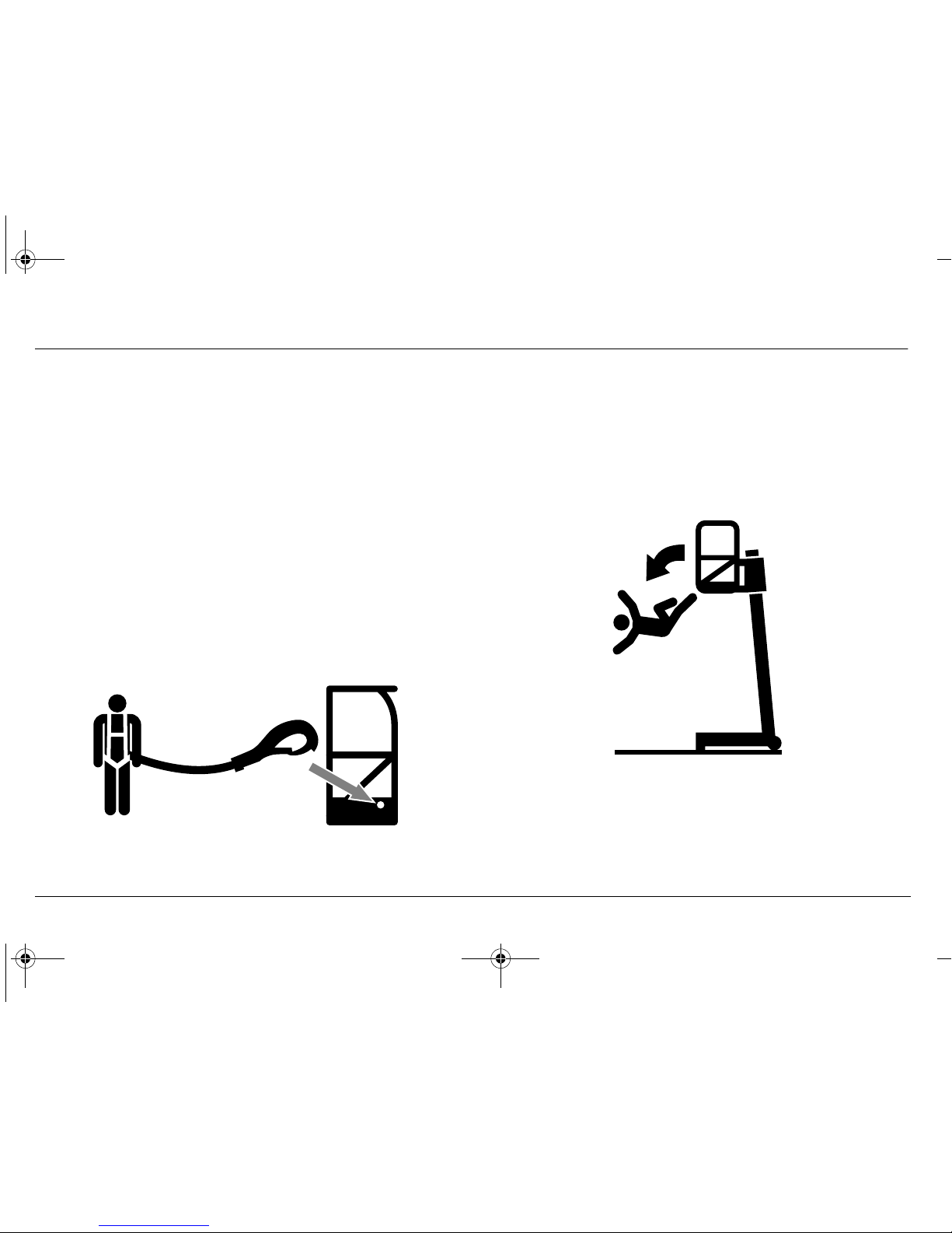
Trip and Fall Hazard
• Do not enter or leave the platform while elevated.
• JLG recommends that the operator utilises a fall restraint
system in the platform with a maximum 36 inch (91.4cm)
lanyard attached to the authorised lanyard anchorage
point. For further information regarding fall protection
requirements on JLG products, contact JLG.
• Before operating the machine, make sure all railings and
gates are fastened in their proper position.
• Keep both feet firmly positioned on the platform floor at all
times. Never use ladders, boxes, steps, planks, or similar
items on platform to provide additional reach.
• Never use the mast assembly to enter or leave the platform.
MAX = 36 in (91.4cm)
FS.book Page 4 Wednesday, February 11, 2009 11:54 AM
Page 15
SECTION 1 - SAFETY PRECAUTIONS
1-877-254-3876 LIFTPOD by JLG 1001070451
1-877-2-LIFTPOD www.liftpod.com 1-5
• Use extreme caution when entering or leaving the platform. Ensure that the mast assembly is fully lowered. Face
the machine when entering or leaving the platform.
• Always maintain "three point contact" with the machine,
using two hands and one foot or two feet and one hand at
all times during entry and exit.
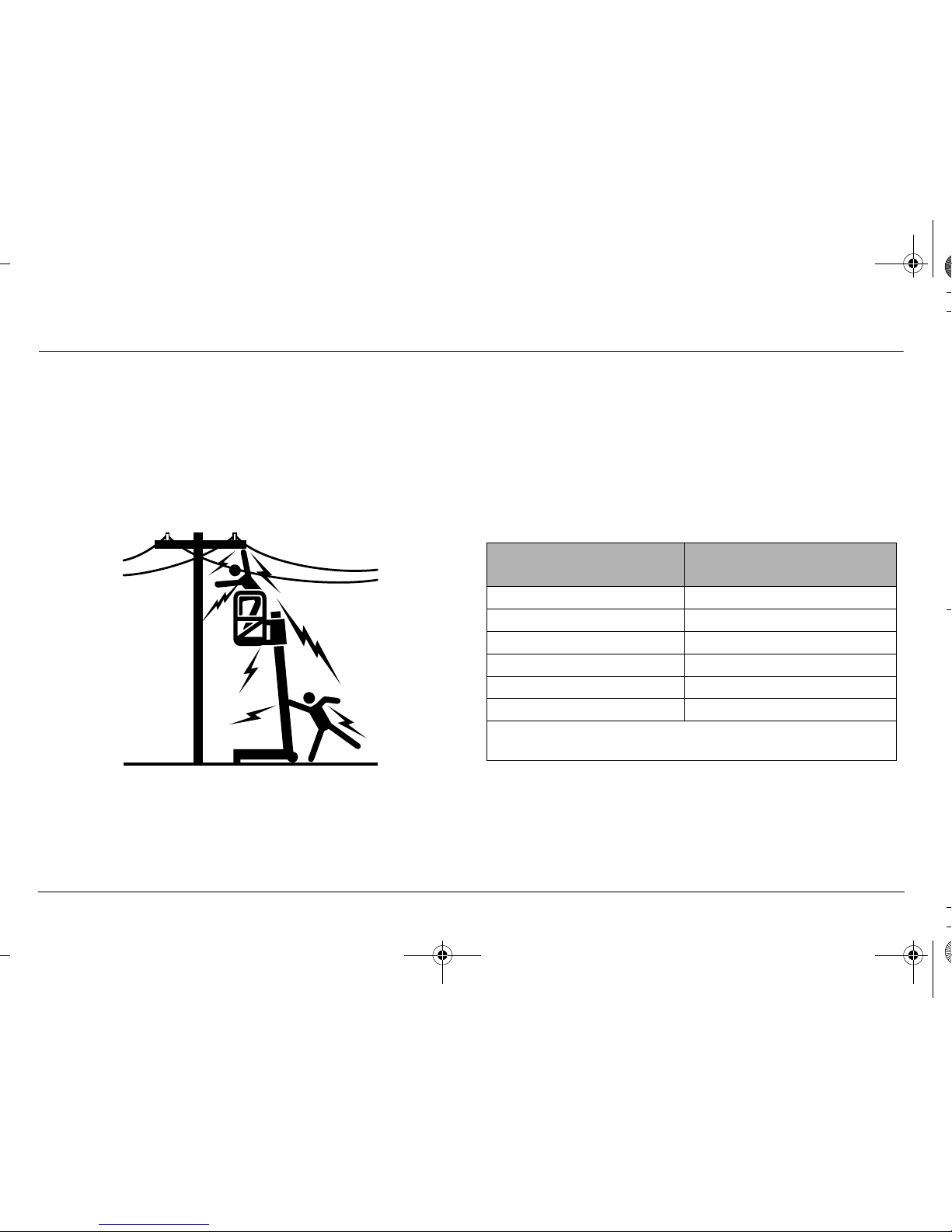
Electrocution Hazard
• This machine is not insulated and does not provide protection from contact or proximity to electrical current.
• Maintain distance from electrical lines, apparatus, or any
energized (exposed or insulated) parts according to the
Minimum Approach Distance (MAD) as shown in
Table 1-1.
• Allow for machine movement and electrical line swaying.
• Maintain a clearance of at least 10 ft. (3m) between any
part of the machine and its occupants, their tools, and
their equipment from any electrical line or apparatus car-
Table 1-1. Minimum Approach Distances (M.A.D.)
VOLTAGE RANGE
(PHASE TO PHASE)
MINIMUM SAFE APPROACH
DISTANCE - Feet (Meters)
0-50KV 10 (3)
Over 50KV to 200KV 15 (5)
Over 200KV to 350KV 20 (6)
Over 350KV to 500KV 25 (8)
Over 500KV to 750KV 35 (11)
Over 750KV to 1000KV 45 (14)
NOTE: This requirement shall apply except where empl oyer, local, or gov-
ernmental regulations are more stringent.
Page 16
SECTION 1 - SAFETY PRECAUTIONS
1001070451 LIFTPOD by JLG 1-877-254-3876
1-6 www.liftpod.com 1-877-2-LIFTPOD
rying up to 50,000 volts. One foot (0.3m) additional clearance is required for every additional 30,000 volts or less.
• The minimum safe approach distance may be reduced if
insulating barriers are installed to prevent contact, and if
the barriers are rated for the voltage of the line being
guarded. These barriers shall not be part of (or attached
to) the machine. The minimum safe approach distance
shall be reduced to a distance within the designed working dimensions of the insulating barrier. This determination shall be made by a qualified person in accordance
with employer, local, or governmental requirements for
work practices near energized equipment.
DO NOT MANEUVER MACHINE OR PERSONNEL INSIDE PROHIBITED
ZONE (MAD). ASSUME ALL ELECTRICAL PARTS AND WIRING ARE
ENERGIZED UNLESS KNOWN OTHERWISE.
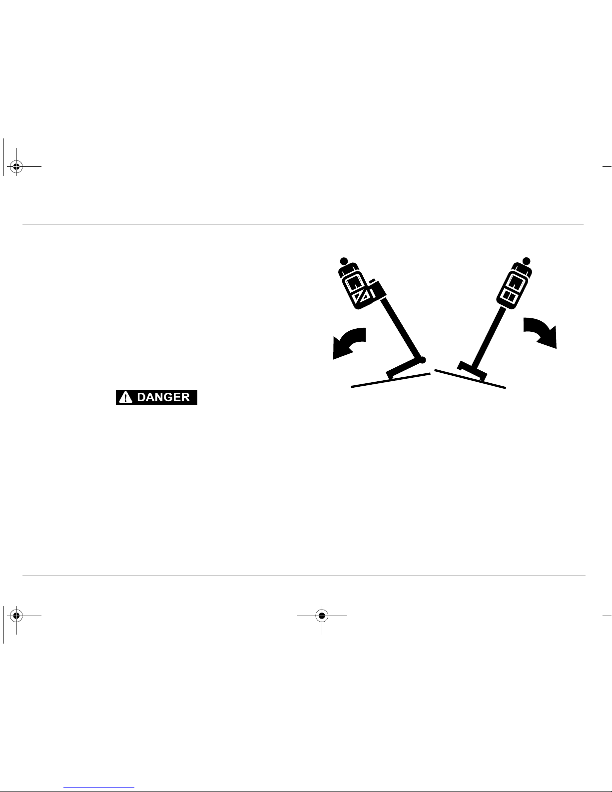
Tipping Hazards
• Only elevate the platform on a firm and level surface.
• Check that the two wheels and the two adjustable feet are
in contact with the ground prior to using the machine.
Adjust the front feet to eliminate any base frame movement and check the bubble level indicates level prior to
use.
FS.book Page 6 Wednesday, February 11, 2009 11:54 AM
Page 17
SECTION 1 - SAFETY PRECAUTIONS
1-877-254-3876 LIFTPOD by JLG 1001070451
1-877-2-LIFTPOD www.liftpod.com 1-7
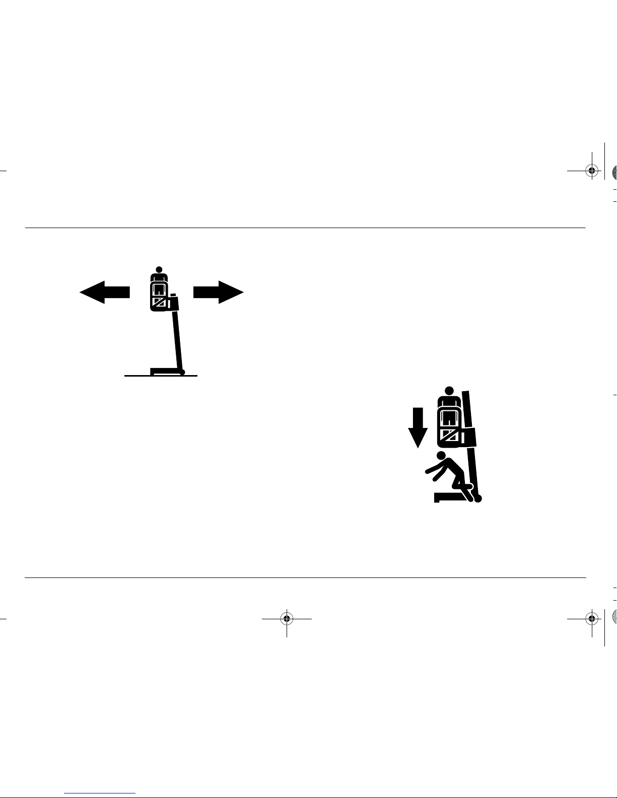
• Do not perform work that will subject unit to a horizontal
force or create a swaying motion of the platform.
• Do not elevate in windy conditions. See Table 5-2
Machine Specifications
• The user should be familiar with the operating surface.
• Do not elevate platform while on a slope, or on an uneven
or soft surface.
• Before using on floors, bridges, and other surfaces, check
allowable capacity of the surfaces.
• Never exceed the maximum platform capacity. Distribute
loads evenly on platform floor and tool tray.
• Keep the base of the machine a minimum of 0.6m (2 ft)
from holes, bumps, drop-offs, obstructions, debris, concealed holes, and other potential hazards at the ground
level.
• Never attempt to use the machine as a crane. Do not tieoff machine to any adjacent structure.
• Do not increase the platform size with unauthorised extensions or attachments, increasing the area exposed to wind
will decrease stability.
• If mast assembly or platform is caught so that one or more
wheels are off the ground, the operator must be removed
before attempting to free the machine. Use cranes, forklift
trucks, or other appropriate equipment to stabilize
machine and remove personnel.
Crushing and Collision Hazards
• Appropriate personal protection equipment must be worn
by all operating and ground personnel.
Page 18

SECTION 1 - SAFETY PRECAUTIONS
1001070451 LIFTPOD by JLG 1-877-254-3876
1-8 www.liftpod.com 1-877-2-LIFTPOD
• Check work area clearances above, on sides, and bottom
of platform while moving, lifting or lowering platform.
• During operation keep all body parts inside platform railing.
• Exercise extreme caution at all times to prevent obstacles
from striking or interfering with operating controls and persons in the platform.
• Ensure that operators of other overhead and floor level
machines are aware of the aerial work platform's presence. Disconnect power to overhead cranes.
• Warn personnel not to work, stand, or walk under a raised
platform. Position barricades on floor as necessary.
1.4 MOVING, LIFTING AND REPOSITIONING
General
Never allow personnel in platform while moving, lifting or repositioning the machine.
This machine shall not be towed by a vehicle.
Ensure platform is fully retracted and completely empty of tools
prior to disassembly, lifting or hauling.
Remove powerpack and tool tray (if fitted) from platform when
transporting in a vehicle.
Refer to the Machine Operation section of this manual for lifting
information.
Additional Safety Information
• Do not use machine as ground for welding.
• Keep all naked flames and sharp edges away from ropes.
• Do not attempt to transport assembled machinery by forklift.
FS.book Page 8 Wednesday, February 11, 2009 11:54 AM
Page 19

SECTION 2 - PREPARATION AND INSPECTION
1-877-254-3876 LIFTPOD by JLG 1001070451
1-877-2-LIFTPOD www.liftpod.com 2-1
SECTION 2. PREPARATION AND INSPECTION
2.1 Personnel Training
The aerial platform is a personnel handling device; so it is necessary that it be operated and maintained only by trained personnel.
The manual supplied with the machine is an important part of
operator training.
Persons under the influence of drugs or alcohol or who are subject
to seizures, dizziness or loss of physical control must not operate
this machine.
Operator Training
Operator training must cover:
1. Use and limitations of the controls in the platform and
emergency controls.
2. Decals, instructions, and warnings on the machine.
3. Rules of the employer and government regulations.
4. Correct assembly of the machine.
5. Use of approved fall protection device.
6. Enough knowledge of the mechanical operation of the
machine to recognize a malfunction or potential malfunction.
7. The safest means to operate the machine where overhead obstructions, other moving equipment, and obstacles, depressions, holes, drop-offs are present.
8. Means to avoid the hazards of unprotected electrical
conductors.
9. Specific job requirements or machine application.
Training Supervision
Training must be done under the supervision of a qualified person
in an open area free of obstructions until the trainee has developed the ability to safely control and operate the machine.
Operator Responsibility
The operator must be instructed that he/she has the responsibility
and authority to shut down the machine in case of a malfunction or
other unsafe condition of either the machine or the job site.
Page 20

SECTION 2 - PREPARATION AND INSPECTION
1001070451 LIFTPOD by JLG 1-877-254-3876
2-2 www.liftpod.com 1-877-2-LIFTPOD
2.2 Preparation, Inspection, and Maintenance
The following table covers the periodic machine inspections and
maintenance recommended by JLG. Consult local regulations for
further requirements for aerial work platforms.
The frequency of inspections and maintenance must be increased
as necessary when the machine is used in a harsh or hostile environment, if the machine is used with increased frequency, or if the
machine is used in a severe manner.
FS.book Page 2 Wednesday, February 11, 2009 11:54 AM
Page 21

SECTION 2 - PREPARATION AND INSPECTION
1-877-254-3876 LIFTPOD by JLG 1001070451
1-877-2-LIFTPOD www.liftpod.com 2-3
Table 2-1. Inspection and Maintenance Table
TYPE FREQUENCY
PRIMARY
RESPONSIBILITY
SERVICE
QUALIFICATION
REFERENCE
Pre-Star t
Inspection
Before star ting each day or at each workshift
change
Operator User or Operator Operation, Safety, Service &
Maintenance Manual
Frequent
Inspection
In service for 3 months; out of ser vice for a
period of more than 3 months; or purchased
used.
Owner, Dealer or User Qualified Mechanic
(*)
Operation, Safety, Service &
Maintenance Manual and
applicable JLG LiftPod
inspection form
Annual Machine
Inspection
Every 12 months Owner, Dealer or User Qualified Mechanic
(*)
Operation, Safety, Service &
Maintenance Manual and
applicable JLG LiftPod
inspection form
5 Year
Replacement
W h e n r o p e i s wo r n o r n o m o r e t h a n 5 y e a r s f r om
first use. Refer to Figure 2-4. for wear criteria.
Owner, Dealer or User Authorized JLG
Service Centre
Factory Training
NOTE: Use this manual to perform inspections.
NOTE: (*) A person who has acquired by training, qualifications, experience or a combination of these, the knowledge and skill enabling the person to
inspect and repair the machine to the level required by the complexity of the task.
Page 22

SECTION 2 - PREPARATION AND INSPECTION
1001070451 LIFTPOD by JLG 1-877-254-3876
2-4 www.liftpod.com 1-877-2-LIFTPOD
Pre-Start Inspection
The Pre-Start Inspection should include each of the following:
1. Cleanliness – Check all surfaces for leakage, debris or
foreign objects.
2. Decals and Placards – Check all for cleanliness and
legibility. Make sure none of the decals and placards are
missing. Make sure all illegible decals and placards are
cleaned or replaced. (Reference Section 5.2, Decal
Installation).
3. Operation, Safety Service & Maintenance Manual –
Make sure a copy of the Operation, Safety, Service &
Maintenance Manual and ANSI Manual of Responsibilities (U.S.A. only) is enclosed in the weather resistant
storage container.
4. Assembly – The machine must be fully assembled in
accordance with Section 3.3.
5. Walk-Around Inspection – Refer to Section 2.3.
6. Powerpack – Charge as required (Section 3.4).
7. Function Check – Once the Walk-Around Inspection is
complete, perform a function check of all systems in an
area free of overhead and ground level obstructions.
Refer to Section 2.4 for more specific instructions.
2.3 DAILY WALK-AROUND INSPECTION
Begin the Walk-Around Inspection at item one (1) as noted on the
diagram Figure 2-1. Continue around machine checking each item
in sequence for the conditions listed in the following check list.
TO AVOID POSSIBLE INJURY, BE SURE DIRECTION SELECTOR IS IN THE
“OFF” POSITION DURING WALK-AROUND INSPECTION.
DO NOT OPERATE MACHINE UNTIL ALL MALFUNCTIONS HAVE BEEN
CORRECTED.
NOTE: Do not overlook visual inspection of the base frame
underside. Check this area for objects, debris, corrosion
and cracks.
NOTE: The mast and carriage components should be clean and
free from oil, grease and dirt. Do not lubricate mast or carriage components, especially brake shoes.
FS.book Page 4 Wednesday, February 11, 2009 11:54 AM
Page 23
SECTION 2 - PREPARATION AND INSPECTION
1-877-254-3876 LIFTPOD by JLG 1001070451
1-877-2-LIFTPOD www.liftpod.com 2-5
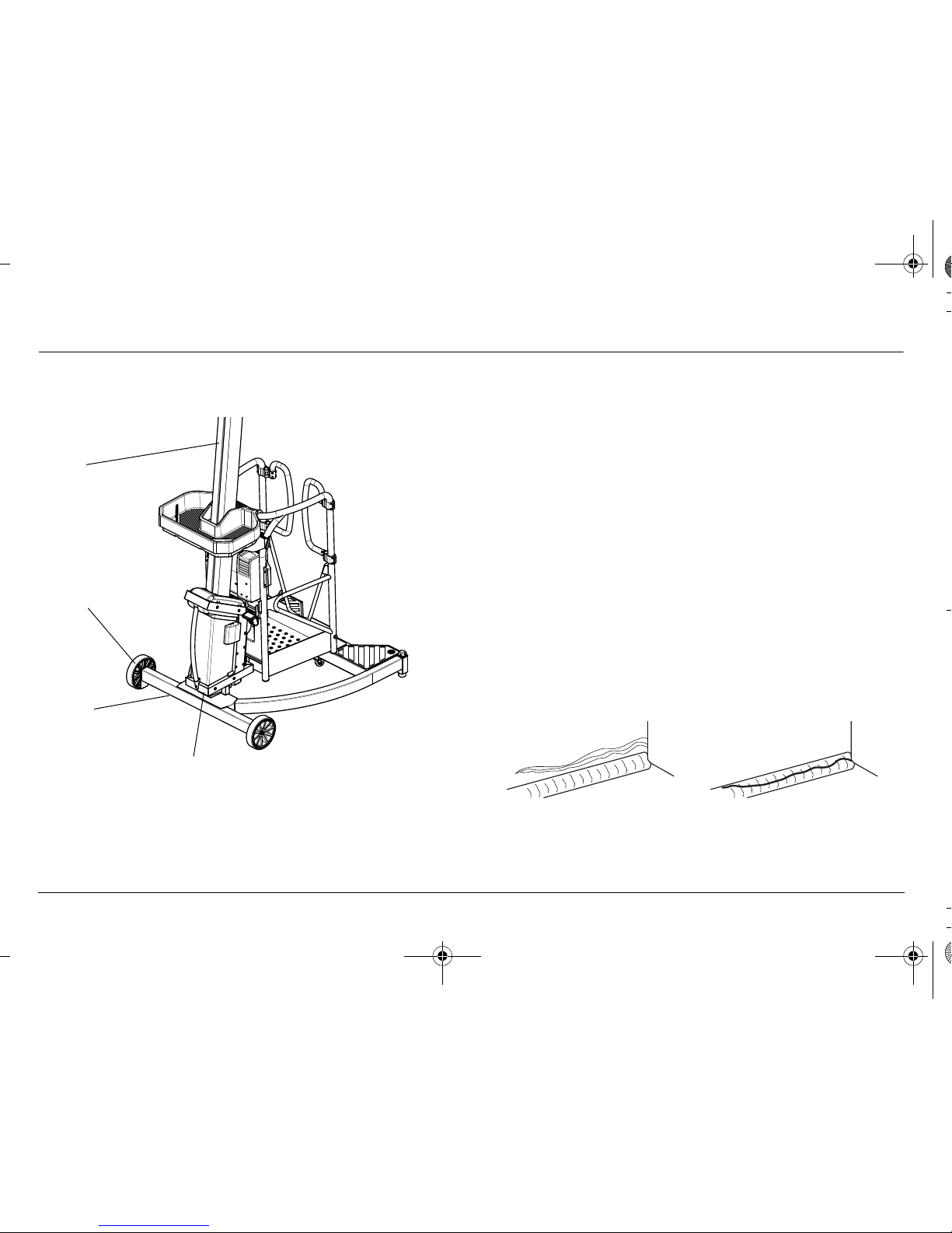
Walk-Around Inspection Components
NOTE: On all components, make sure there are no loose or miss-
ing parts, everything is securely fastened, no visible damage, or excessive wear exists in addition to any other
criteria mentioned.
1. Rear Wheels - Check for any debris stuck to or around
wheels. Make sure bolts are fastened.
2. Base Frame - Check for cracks or corrosion, especially
around the mast-stump base (see Figure 2-2.). Check
level bubble is clean and secure.
3. Mast Assembly - No cracks or corrosion, especially
around base and flange; no excess wear, kinks, nicks or
damage; carriage running surfaces smooth and unobstructed; free of dust, oil & grease.
4. Carriage Frame - check for visible cracks; check rollers
for visible wear; check carriage frame welds for visible
cracks (see Figure 2-2.).
Figure 2-1. Daily Walk-Around Inspection
(Sheet 1 of 2)
1
2
3
4
REAR
FRONT
Figure 2-2. Examples of cracks
Parent Metal Crack
Weld Crack
Page 24
SECTION 2 - PREPARATION AND INSPECTION
1001070451 LIFTPOD by JLG 1-877-254-3876
2-6 www.liftpod.com 1-877-2-LIFTPOD
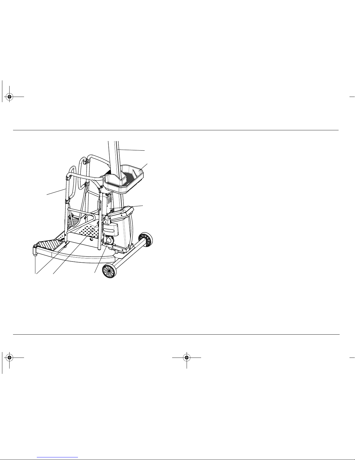
5. Gearbox - check for any oil leaks, especially around
bottom shaft seal.
6. Swivel Castor Mechanism and Adjustable Feet Check for any debris stuck to or around wheels or
mechanism. Check adjustable feet for damage. Rubber
pads and tire must be in good order.
7. Rope Assembly - Check rope is not frayed or damaged
(Figure 2-4.). Ensure it is tensioned tightly and seated
properly around take-up drum (view via carriage inspection window - see Figure 6-2.). Ensure it is seated correctly over mast-cap (Figure 2-5.) and at anchor point at
back of mast (Figure 2-6.). Indications that rope needs
replacement include:
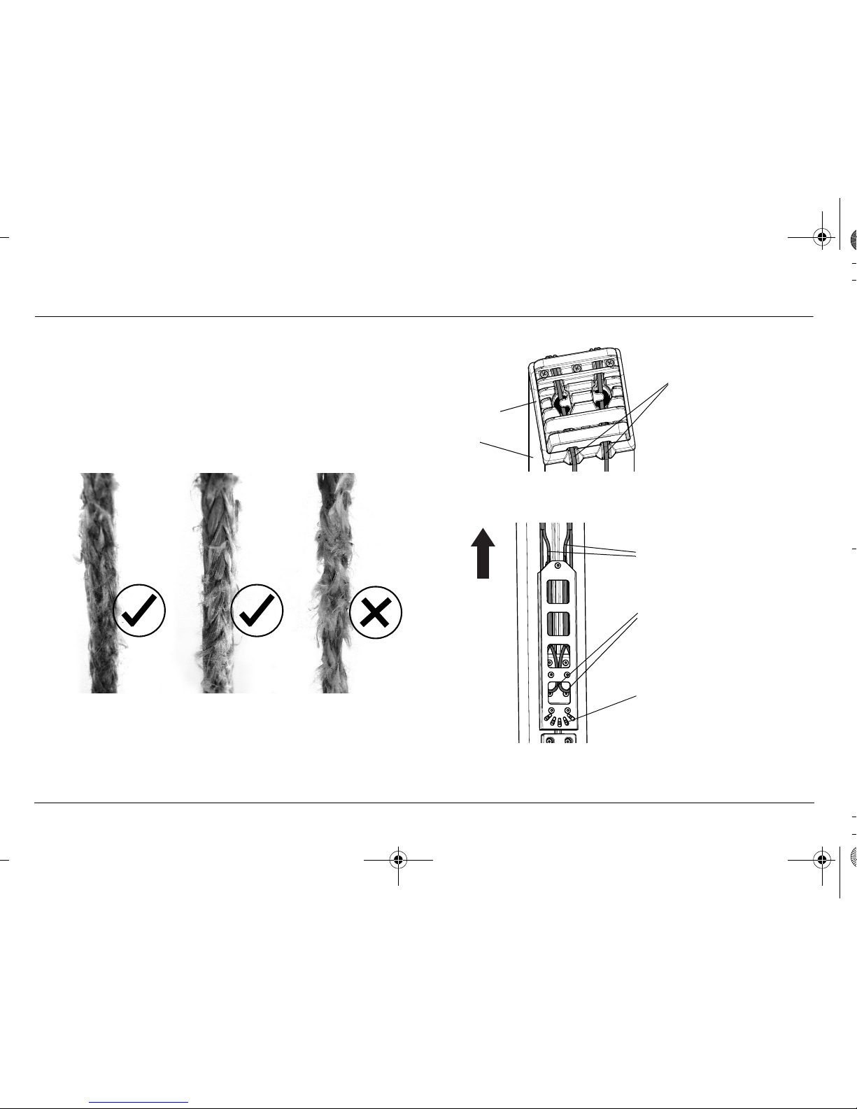
1. Frayed or fluffy rope (Figure 2-4.)
2. Braiding no longer visible
3. Sections of rope thinned down in diameter.
8. Manual Descent Crank - Ensure it is present and
securely attached (Figure 2-8.).
9. Powerpack and Control Console (optional) - Ensure it
is properly mounted and secured. Button, triggers and
switches not obscured or damaged; decals secure and
legible; emergency stop switch reset for operation; control markings legible. Battery is installed and secure.
Figure 2-3. Daily Walk-Around Inspection
(Sheet 2 of 2)
5
7
9
10
8
FRONT
REAR
11
6
FS.book Page 6 Wednesday, February 11, 2009 11:54 AM
Page 25
SECTION 2 - PREPARATION AND INSPECTION
1-877-254-3876 LIFTPOD by JLG 1001070451
1-877-2-LIFTPOD www.liftpod.com 2-7
10. Platform Assembly and Gate - Check mounting pins
are not loose; platform railing is undamaged; platform
latch is engaged on carriage (Figure 2-7.); self-closing
entry gates are in proper working order; no cracks or
corrosion visible.
11. Tool Tray - See next page for Tool Tray Pre-Start Inspection Procedure.
Figure 2-4. Examples of new, acceptable and
unacceptable ropes
Figure 2-5. Ropes retained in mast cap
Figure 2-6. Rope anchor points
Check both ropes
are retained in
groove in cap
Mast
Mast Cap
Check that each termination is
engaged under its anchor point
by viewing through the cover.
The two upper rope tails
should be slack.
The lower rope loop should
be tight around anchor.
Top o f
Mast
Page 26
SECTION 2 - PREPARATION AND INSPECTION
1001070451 LIFTPOD by JLG 1-877-254-3876
2-8 www.liftpod.com 1-877-2-LIFTPOD
Figure 2-7. Platform latch shown engaged
Figure 2-8. Location of manual descent crank
FS.book Page 8 Wednesday, February 11, 2009 11:54 AM
Page 27

SECTION 2 - PREPARATION AND INSPECTION
1-877-254-3876 LIFTPOD by JLG 1001070451
1-877-2-LIFTPOD www.liftpod.com 2-9
Tool Tray Pre-Start Inspection
Prior to use of the tool tray, check the following:
• Tool tray is seated securely on the platform rail.
• No cracks or bends in tray.
• Both of the clips are securely attached to the platform rail
(Figure 2-9.).
• Capacity decal is in place and legible.
Maximum Load: The maximum permissible load on the tool tray
is 15kg (33 lb.) evenly distributed.
Figure 2-9. Tool tray installation
Page 28

SECTION 2 - PREPARATION AND INSPECTION
1001070451 LIFTPOD by JLG 1-877-254-3876
2-10 www.liftpod.com 1-877-2-LIFTPOD
2.4 FUNCTION CHECK
Once the Walk-Around inspection is complete, perform a function
check of all systems in an area free of overhead and ground level
obstructions.
IF THE MACHINE DOES NOT OPERATE PROPERLY, TURN OFF THE
MACHINE IMMEDIATELY! REPORT THE PROBLEM TO THE PROPER
MAINTENANCE PERSONNEL. DO NOT OPERATE THE MACHINE UNTIL IT
IS DEEMED SAFE FOR OPERATION.
Function Check Items
1. Base Brake - Step on base to ensure the swivel castor
retracts properly.
2. Adjustable Feet - Check both rotate freely up and
down; check that rubber pads are installed and not
excessively worn.
3. Emergency Stop Button (optional powerpack) - ensure
all machine functions are disabled when the emergency
stop button is activated (pressed in) - then RESET the
emergency stop button by twisting it in the direction
indicated by the arrows.
TO AVOID COLLISION AND INJURY IF PLATFORM DOES NOT STOP
WHEN A CONTROL IS RELEASED, USE THE EMERGENCY STOP BUTTON
TO STOP THE MACHINE.
FS.book Page 10 Wednesday, February 11, 2009 11:54 AM
Page 29

SECTION 3 - MACHINE OPERATION
1-877-254-3876 LIFTPOD by JLG 1001070451
1-877-2-LIFTPOD www.liftpod.com 3-1
SECTION 3. MACHINE OPERATION
3.1 GENERAL
NOTE: The manufacturer has no direct control over machine
application and operation. The user and operator are
responsible for conforming with good safety practices.
This section provides the necessary information needed to understand control function and operation.
3.2 MACHINE DESCRIPTION
The JLG LiftPod is a battery powered aerial work platform. The
platform is mounted to a mast and elevating carriage mechanism.
The personnel lift's intended purpose is to provide personnel
access to areas above level ground. The platform must only be
elevated on a firm, level, uniform surface.
The machine consists of seven parts:
1. Base Frame
2. Carriage/Mast Assembly
3. Platform
4. Powerpack (optional)
5. Spare Battery (optional)
6. Charger (optional)
7. Tool Tray (optional)
Figure 3-1. Main components
1
2
3
6
5
7
4
Page 30

SECTION 3 - MACHINE OPERATION
1001070451 LIFTPOD by JLG 1-877-254-3876
3-2 www.liftpod.com 1-877-2-LIFTPOD
The primary control console is located within the removable and
rechargeable powerpack.
The powerpack is attached to the machine within the platform.
With the installed powerpack, the operator can raise or lower the
platform through its controls.
The machine has a self retracting swivel castor mounted under the
front of the base which retracts out of ground contact when
loaded.
The base of the machine consists of two fixed wheels and two
adjustable feet, for leveling and stabilizing the base within 2
degrees of level from front and back only. Prior to operation the
adjustable feet are to be engaged to a point where the base is
level as seen on the level bubble (Figure 3-6.).
Detailed Description
Figure 3-2. Base frame component description
Fixed Wheel
Adjustable Foot
Self Retracting Swivel Castor
Adjustable Foot
Fixed Wheel
Carriage Rests
Mast Stump
Level Bubble
Retracting Castor
Release Lever
FRONT
(travel stops)
Step Plate
FS.book Page 2 Wednesday, February 11, 2009 11:54 AM
Page 31

SECTION 3 - MACHINE OPERATION
1-877-254-3876 LIFTPOD by JLG 1001070451
1-877-2-LIFTPOD www.liftpod.com 3-3
Platform Configuration Mast/Carriage Components
Figure 3-3. Platform component description
Platform Swing Gates
Mounting Pin
Authorized Lanyard Anchorage Point
Platform Locator
Platform Latch
Mounting Pin
Powerpack Mounts
Powerpack Latch Mount
Manual Storage
Compartment (other side)
Figure 3-4. Mast/carriage component description
Mast Cap
Carriage Frame
Gearbox
Carry Handle
Drum Inspection
Rope Anchor (at back)
Driveshaft
Lifting Ropes
Window
Platform Mounting
Pin Holes
Mast
(orange)
Lower Facing Shaft Stub
Page 32

SECTION 3 - MACHINE OPERATION
1001070451 LIFTPOD by JLG 1-877-254-3876
3-4 www.liftpod.com 1-877-2-LIFTPOD
3.3 MACHINE OPERATION
General
When the platform reaches the bottom of its travel, the rest position, the drive mechanism overrunning clutch creates a ratcheting,
or buzzing noise, indicating that the machine has reached the fully
lowered position.
The machine is fitted with an emergency brake which activates
when the tension in the lifting ropes goes below 40kg (88 lbs).
When the platform is lowered to the rest position, the emergency brake swings into position, stopping further rotation of
the rope drum and engaging a carriage lock-down latch onto
the mast.
IN THE EVENT THAT THE CARRIAGE LATCHES TO THE MAST WHEN
FULLY LOADED OR THE ROPE CONTINUES TO FEED OUT AFTER THE
PLATFORM HAS REACHED THE REST POSITION, THE MACHINE IS NOT
WORKING PROPERLY AND MUST NOT BE USED UNTIL IT IS INSPECTED
AND REPAIRED BY A QUALIFIED PERSON.
NOTE: Do not attempt to lift the mast off the base unless the car-
riage has been fully lowered.
Getting Started
The following control conditions must be met before the machine
can be operated from the platform controls:
• Batteries must contain enough voltage to operate. Low
battery warning on battery test panel indicates the need to
charge the batteries. Batteries should be charged for 24
hours prior to first use.
• Emergency stop switch on optional powerpack must be in
the RESET position (out).
• Both platform swing-in entry gates must be closed.
Assembly of the Machine
The JLG LiftPod is a user assembled machine. There are three
basic parts that need to be assembled for operation. These parts
are the Base Frame 1, Carriage/Mast Assembly 2, and the Platform 3. Optional parts include the Powerpack 4, and the Tool Tray
5 (Figure 3-1.).
1. Position the base frame on a firm, level, uniform, sup-
porting surface.
2. Push down on the base frame’s step plate until the
swivel castor retracts and the base sits on the adjustable
feet (Figure 3-5.). The machine now rests on the two rear
wheels, and the two adjustable feet at the front.
FS.book Page 4 Wednesday, February 11, 2009 11:54 AM
Page 33

SECTION 3 - MACHINE OPERATION
1-877-254-3876 LIFTPOD by JLG 1001070451
1-877-2-LIFTPOD www.liftpod.com 3-5
CRUSH HAZARD - KEEP FEET CLEAR OF ADJUSTABLE FEET AND
UNDERNEATH BASE WHEN STEPPING ON BASE TO RETRACT CASTOR.
3. Turn the adjustable feet until the level bubble is centred
(see Figure 3-6.)
DO NOT USE THE MACHINE IF THE BASE CAN NOT BE LEVELLED.
Figure 3-5. Carriage/mast to base mounting
PUSH DOWN
Adjustable Foot
Adjustable Foot
Figure 3-6. Detail view of level bubble
Level Bubble
Rotating Knob
adjusts foot height
Page 34

SECTION 3 - MACHINE OPERATION
1001070451 LIFTPOD by JLG 1-877-254-3876
3-6 www.liftpod.com 1-877-2-LIFTPOD
4. Slide the carriage/mast assembly onto the mast stump.
Make sure it is properly aligned and fully engaged.
Never force it into position (see Figure 3-5.).
5. Attach the platform to the carriage (see Figure 3-7.).
• Make sure the platform’s mounting pins are
aligned with the holes in the carriage (A), then
drop slowly down to seat properly.
• Ensure the platform locator (B) is properly
engaged in the bottom of the carriage frame.
• Make sure the platform latch (C) is fully
engaged. CHECK: Try to lift the platform out,
if it does not release, then the platform has
engaged properly.
Figure 3-7. Attaching the platform to the carriage
Fully Engaged
Figure 3-8. Platform attachment checks
(C)
(B)
(A)
FS.book Page 6 Wednesday, February 11, 2009 11:54 AM
Page 35

SECTION 3 - MACHINE OPERATION
1-877-254-3876 LIFTPOD by JLG 1001070451
1-877-2-LIFTPOD www.liftpod.com 3-7
NOTE: When reversing the procedure to disassemble the
machine, pull the platform latch handle (C) to disengage
the platform from the carriage.
6. Fasten lanyard securely around the handle of the cordless drill. Attach the cordless drill to the top of the driveshaft, either using the supplied 7/16 (11mm) deep well
drive socket (located in manual pouch), or by tightening
the drill chuck directly to the hexagon on top of the
driveshaft (see Figure 3-9.).
CORDLESS DRILL LANYARD MUST BE INSTALLED BEFORE ELEVATING.
DO NOT DROP DRILL.
Figure 3-9. Cordless drill installation
Driveshaft
Drive Socket
Lanyard
Cordless Drill
(optional)
Manual Pouch
Page 36

SECTION 3 - MACHINE OPERATION
1001070451 LIFTPOD by JLG 1-877-254-3876
3-8 www.liftpod.com 1-877-2-LIFTPOD
7. Place the powerpack (optional equipment) against the
platform uprights, closest to the mast, and slide it down
until it clicks, indicating it is fully seated (see Figure 3-
10.).
NOTE: When reversing the procedure to disassemble the
machine, pull the powerpack release latch (see Figure 3-
17.) while lifting to disengage the powerpack from the
platform.
8. Tool tray: (optional equipment)
Place on top rail of platform, and fasten the two clips
firmly around the rail (see Figure 2-9.).
THE WEIGHT OF OBJECTS CARRIED IN A PLATFORM ACCESSORY,
ALONG WITH PERSONNEL AND EQUIPMENT PLACED IN THE PLATFORM MUST NOT EXCEED THE MAXIMUM RATED PLATFORM CAPACITY. SEE TABLE 5-4.
DO NOT PLACE ITEMS IN THE TOOL TRAY IN THE INDICATED AREA
WHEN MAST IS BELOW THE TOOL TRAY’S TOP SURFACE (SEE FIGURE
3-11.).
Figure 3-10. Powerpack positioned and latched into
place
FS.book Page 8 Wednesday, February 11, 2009 11:54 AM
Page 37

SECTION 3 - MACHINE OPERATION
1-877-254-3876 LIFTPOD by JLG 1001070451
1-877-2-LIFTPOD www.liftpod.com 3-9
Disassembly of the Machine
Reverse the above steps to disassemble the machine.
DO NOT ATTEMPT TO LIFT THE MAST OFF THE BASE UNLESS THE CARRIAGE HAS BEEN FULLY LOWERED.
Figure 3-11. Tool tray load restriction
NO-LOAD AREA
Page 38

SECTION 3 - MACHINE OPERATION
1001070451 LIFTPOD by JLG 1-877-254-3876
3-10 www.liftpod.com 1-877-2-LIFTPOD
3.4 Powerpack (Optional Equipment)
Battery Charging Operation
DO NOT SHORT CIRCUIT THE BATTERY. DO NOT OPEN THE BATTERY
PACK AS THERE IS A DANGER OF CAUSING A SHORT CIRCUIT.
PROTECT THE BATTERY AGAINST HEAT, INCLUDING AGAINST CONTINUOUS DIRECT SUN EXPOSURE OR OPEN FLAME.
New batteries and batteries that have not been used for a long
period must be fully charged. They will not reach their full capacity
until fully charged and discharged through several cycles. Battery
performance will be limited at low temperatures. The battery can
be charged and discharged hundreds of times but will eventually
wear out and need to be replaced.
A significantly reduced operat-
ing period after charging indicates that the battery must be
replaced.
Battery Charge Status Lights
The powerpack batteries indicates battery low voltage at three (3)
warning levels.
Figure 3-12. Battery charging plug and tester
Figure 3-13. Charge status lights
Trickle Charge Indicator
Tri c k le C h a r g e P l u g
Charge Status Test Button
Charge Status Lights
3 green lights - Battery
is fully charged.
2 green lights - Battery
needs recharging/
replacing soon.
1 green light - Battery
needs recharging/
replacing as soon as
possible.
FS.book Page 10 Wednesday, February 11, 2009 11:54 AM
Page 39

SECTION 3 - MACHINE OPERATION
1-877-254-3876 LIFTPOD by JLG 1001070451
1-877-2-LIFTPOD www.liftpod.com 3-11
Charging the Batteries Using the Fast Charge Station
NOTE: USE ONLY THE SUPPLIED CHARGING STATION.
1. Remove battery from powerpack (Figure 3-14.).
2. Place battery into recharging dock.
3. Plug recharge dock into AC voltage wall outlet.
4. Once the green LED has stopped flashing, the power-
pack is fully charged.
TO REDUCE THE RISK OF FIRE OR ELECTRIC SHOCK, CAREFULLY FOLLOW THESE INSTRUCTIONS.
If the shape of the plug does not fit the power outlet, use an
attachment plug adaptor of the proper configuration for the power
outlet.
Unless the battery is being charged, always remove the battery
from the fast charger.
Fast Charge Indicator Light Guide
SOLID GREEN: Insert battery or remove fully charged battery
Figure 3-14. Removing the battery from the powerpack
Pull and lift battery
release latch to
disengage battery
from powerpack
Figure 3-15. Recharge dock operations and indicators
Fault Indicator (RED)
Charge Indicator (GREEN)
Battery
Battery Release
Recharging Dock
Page 40

SECTION 3 - MACHINE OPERATION
1001070451 LIFTPOD by JLG 1-877-254-3876
3-12 www.liftpod.com 1-877-2-LIFTPOD
FLASHING GREEN: Battery is charging.
SOLID RED: Charging is temporarily halted to allow battery to
cool down. Charging will continue automatically.
FLASHING RED: Please reinsert battery. If the red light continues
to flash, the battery or the charger may be faulty.
To troubleshoot whether the battery or the charger is at fault, insert
another battery. If this battery charges, the other battery is faulty
and must not be used. If the red light continues to flash, the
charger is faulty.
Power Supply Cord
Below is the specification of the power supply chord to be used
with the fast charger within the U.S.A.
Use UL listed detachable power supply cord - No. 18 AWG, two
conductors, VW-1, 221°F (105°C), 125V, Type:SPT-2, minimum 5 ft.
11 in. (1.8m), maximum 9 ft. 10 in. (3m) long. Provided with a
molded-on, polarized attachment plug with a 15A, 125V (NEMA 115P) configuration and a molded-on connector which mates with
the power inlet.
3.5 Operation
Cordless Drill
1. Drive Socket (optional)
2. Chuck
3. Torque Control (optional)
4. Power Trigger
5. Speed Controller (optional)
6. Drill/Hammer Function Selector (optional)
Figure 3-16. Typical cordless drill interface devices
7
3
2
8
5
6
1
4
FS.book Page 12 Wednesday, February 11, 2009 11:54 AM
Page 41

SECTION 3 - MACHINE OPERATION
1-877-254-3876 LIFTPOD by JLG 1001070451
1-877-2-LIFTPOD www.liftpod.com 3-13
7. Direction Selector
8. Battery Pack
Please follow the manufacturer’s instructions on safe operation
and maintenance of the cordless drill.
JLG recommends a cordless drill of at least 18V capacity.
Ensure cordless drill’s optional "Hammer" setting is disabled and
cordless drill is in "Drill" mode on medium to high torque. Do not
set to maximum torque setting.
USE ONLY CORDLESS DRILLS. DISCONTINUE USE OF THE CORDLESS
DRILL IF A FAULT IS DETECTED. ENSURE CORDLESS DRILL IS IN
"DRILL" MODE ON MEDUIM TO HIGH TORQUE SETTING, BUT NOT MAXIMUM TORQUE SETTING TO AVOID INJURY.
Powerpack Control Console (Optional Equipment)
1. Enable Trigger
2. Battery Release Latch
3. Battery Trickle Charge Plug
4. Emergency Stop Button
5. Direction Selector
6. Speed Trigger
7. Powerpack Release Latch
Figure 3-17. Powerpack control console
1
2
3
4
5
6
7
Page 42

SECTION 3 - MACHINE OPERATION
1001070451 LIFTPOD by JLG 1-877-254-3876
3-14 www.liftpod.com 1-877-2-LIFTPOD
The powerpack is splash resistant allowing a safe descent if it
starts to rain while the unit is elevated, but JLG does not recommend that the powerpack be used in rain or exposed to water.
Whenever the machine is not in use, set the direction selector to
the OFF position.
DISCONTINUE USE OF THE POWERPACK IF A FAULT IS DETECTED.
NOTICE
DO NOT PRESSURE-WASH THE POWERPACK.
MAKE SURE YOU CHECK THE REMAINING CHARGE INSIDE THE POWERPACK’S BATTERY BEFORE ELEVATING THE PLATFORM BY PRESSING
THE CHARGE INDICATOR TEST BUTTON. IF ONLY ONE LIGHT COMES
ON, REPLACE WITH FULLY CHARGED BATTERY.
NOTICE
IF THE POWERPACK DOES NOT ACTIVATE WITH A CHARGED BATTERY
INSTALLED, THE EMERGENCY BUTTON MAY NEED TO BE RESET
(TWIST IN DIRECTION OF ARROWS AND POP OUT).
Elevating
Make sure the pre-start inspection has been completed, the
machine is safe to use, and the base is level.
Move the cordless drill’s direction selector to the "screw-in" (clockwise) direction.
Hold the drill’s handle firmly, push it down to automatically disengage the driveshaft interlock, and squeeze the trigger to elevate.
Stop using the cordless drill if any part of it becomes excessively
hot. Wait until drill has cooled down and then continue operation.
Figure 3-18. Cordless drill elevation
FS.book Page 14 Wednesday, February 11, 2009 11:54 AM
Page 43

SECTION 3 - MACHINE OPERATION
1-877-254-3876 LIFTPOD by JLG 1001070451
1-877-2-LIFTPOD www.liftpod.com 3-15
If using the optional powerpack instead of a cordless drill, move
the direction selector switch to the UP position (Figure 3-19.).
Hold the handle so the enable trigger is pressed and squeeze the
speed trigger. The function speed is proportional to how far the
speed trigger is pressed.
To stop, simply release the speed trigger. A slow release makes
the platform come to a smooth stop.
Most cordless drills and the motor in the powerpack are fitted with
thermal overload protection. In case of overheating, this cuts
power to the motor. The cutout automatically resets itself when the
motor has cooled down, allowing normal operation to resume.
Depending on ambient temperature this can take 5 to 30 minutes.
Engaging the triggers to run the cooling fan will decrease the thermal reset time.
The manual descent procedure (Section 4.1) can be used to lower
the platform if required.
• Do not attempt to elevate with no load in the platform.
• The platform has a total capacity of 150kg (330 lb.).
• The machine is not intended for use by children.
• Children must be supervised to
ensure they do not use or play with
the machine.
•Only one person is allowed to be
lifted by the platform.
Figure 3-19. Detail view of direction selector
Direction Selector
UP Position
DOWN Position
OFF Position
Figure 3-20. Detail view of enable & speed triggers
Enable Trigger
Speed Trigger
Page 44

SECTION 3 - MACHINE OPERATION
1001070451 LIFTPOD by JLG 1-877-254-3876
3-16 www.liftpod.com 1-877-2-LIFTPOD
Descending
CRUSHING HAZARD - BE AWARE OF DESCENDING PLATFORM WHEN
LOWERING THE PLATFORM. KEEP HANDS OR FEET OFF THE MAST
ASSEMBLY AND FROM BENEATH PLATFORM.
On the cordless drill, move the direction selector to the "unscrew"
(anti-clockwise) direction. Push the cordless drill down to disengage the driveshaft interlock and squeeze the trigger to descend.
If using the optional powerpack, move the direction selector to the
DOWN position. Hold the handle so the enable trigger is pressed
and squeeze the speed trigger.
To stop at anytime, simply release the speed trigger.
To exit the platform, ensure the platform is all the way down until it
touches-down on the base. This will engage the drive mechanism’s overdrive ratchet, making a ratcheting sound. This means
the platform has reached its lowest position and the trigger should
be released.
NOTE: Before transporting, maneuvering or disassembling
machine, ensure the platform is all the way down. The
carriage lock is engaged automatically when the platform
is fully lowered and all load is removed.
Powerpack Emergency Stop/Shutdown Button
If the platform stops responding to operator input at any time while
the platform is moving, use the emergency stop button to cut the
power to the motor.
Figure 3-21. Emergency stop button operation
Press down to activate
Rotate clockwise
Emergency Stop
to release/reset
Emergency Stop
FS.book Page 16 Wednesday, February 11, 2009 11:54 AM
Page 45

SECTION 3 - MACHINE OPERATION
1-877-254-3876 LIFTPOD by JLG 1001070451
1-877-2-LIFTPOD www.liftpod.com 3-17
Unpowered Descent
The platform manual descent crank (Figure 2-8.) is provided to:
• Allow the platform operator to lower the platform in the
event that the cordless drill or powerpack batteries run out
of sufficient charge to lower the platform;
• Allow ground personnel to lower the platform in event that
the platform operator becomes incapacitated.
For emergency operation please see Section 4 - Emergency Procedures.
3.6 TRANSPORT AND MANEUVERING (MOVING)
General
The machine may be manually maneuvered or transported in a
vehicle disassembled.
DO NOT ATTEMPT TO TRANSPORT OR MOVE MACHINE UNLESS THE
CARRIAGE IS FULLY DOWN AND THE CARRIAGE TO MAST LOCK IS
ENGAGED. DO NOT MOVE MACHINE WITH PERSONNEL IN PLATFORM.
WHEN TRANSPORTING THE MACHINE, ENSURE THE ROPES ARE PROTECTED AND NOT DAMAGED.
The machine may be moved around a worksite using the following
methods:
• Fully assembled, pushed around the floor using the
wheels and castor;
• Fully assembled, tilted over.
• Disassembled, with each major component carried separately.
Page 46

SECTION 3 - MACHINE OPERATION
1001070451 LIFTPOD by JLG 1-877-254-3876
3-18 www.liftpod.com 1-877-2-LIFTPOD
Fully Assembled Maneuvering
There are two ways to move the assembled machine:
PUSHED UPRIGHT
The machine can be pushed around using the built-in wheels and
castor. The floor is required to be smooth, level, clean and dry.
There can be no significant load on the machine while it is being
rolled around, or the swivel castor will retract automatically.
Lift the handle to engage the swivel castor.
The machine is easily positioned as required.
The swivel castor underneath the step plate toggles out of the way
when loaded, and the machine rests securely on the rear wheels
and two adjustable feet.
PUSHED TILTED OVER
The machine can be tilted over and maneuvered as shown in
Figure 3-23.
NOTE: Ensure powerpack and tool tray are securely attached
and tool tray and platform are empty before moving.
Figure 3-22. Activate the handle to extend the swivel
castor
Figure 3-23. Maneuvering when tilted back
FS.book Page 18 Wednesday, February 11, 2009 11:54 AM
Page 47

SECTION 3 - MACHINE OPERATION
1-877-254-3876 LIFTPOD by JLG 1001070451
1-877-2-LIFTPOD www.liftpod.com 3-19
ONLY ATTEMPT TO TILT THE UNIT BACK, OR RETURN TILTED UNIT TO
THE UPRIGHT POSITION, ON A FLAT AND LEVEL SURFACE, CLEAR OF
ANY PERSONNEL. WHEELS SHOULD BE CHOCKED TO AVOID ROLLING
DURING TILT OPERATION. ENSURE A FIRM GRIP WITH TWO HANDS ON
THE MAST, AND ENSURE WEIGHT IS DISTRIBUTED TO AVOID THE
USER OR THE MACHINE BEING THROWN BY THE MOVING WEIGHT OF
THE MACHINE.
Disassembled Maneuvering
The machine is designed to be used and assembled by a single
operator. To improve portability, it is divided into a number of self
contained sub-assemblies (see Figure 3-1.).
TAKE PRECAUTIONS TO AVOID MANUAL HANDLING INJURIES. USE
PROPER LIFTING TECHNIQUES: BEND AT KNEES ONLY, NEVER TWIST
YOUR BACK WHEN HOLDING OR CARRYING A LOAD, AND/OR GET HELP.
ONLY CARRY ONE COMPONENT AT A TIME.
The mast/carriage assembly can be carried by the built-in handle
(see Figure 3-24.).
Figure 3-24. Mast/carriage handle
Page 48

SECTION 3 - MACHINE OPERATION
1001070451 LIFTPOD by JLG 1-877-254-3876
3-20 www.liftpod.com 1-877-2-LIFTPOD
The base frame can be moved by the mast stump and the frame to
fit through doorways sideways (see Figure 3-25.).
Parking and Storage
• Move machine to a dry, well-protected and well-ventilated
area out of direct sunlight.
• Ensure the platform is fully lowered. If installed, move the
powerpack’s direction control switch to the OFF position.
• If necessary, remove the cordless drill or optional powerpack from the platform to prevent unauthorized use.
• Ensure the swivel castor is retracted and the machine is
resting on the adjustable feet.
NOTICE
DO NOT STORE IN LOCATIONS WHERE THE MACHINE MAY ACCUMULATE ICE, GREASE OR AIRBOURNE DEBRIS.
Vehicle Transport
When transporting the machine by vehicle, it should be disassembled into its major components (see Figure 3-1.) and each component secured separately. Restrain each component of the
machine securely during transport. Ensure the swivel castor is
retracted in the base frame and the base frame is resting on the
adjustable feet.
NOTICE
USE OF EXCESSIVE FORCE WHEN SECURING MACHINE CAN CAUSE
DAMAGE TO THE MACHINE.
Secure machine to the transport vehicle with adequately rated
rope or straps. Do not overtension such devices and place a
buffer between the device and any part of the machine.
Figure 3-25. Moving base through a door
FS.book Page 20 Wednesday, February 11, 2009 11:54 AM
Page 49

SECTION 4 - EMERGENCY PROCEDURES
1-877-254-3876 LIFTPOD by JLG 1001070451
1-877-2-LIFTPOD www.liftpod.com 4-1
SECTION 4. EMERGENCY PROCEDURES
4.1 GENERAL INFORMATION
This section explains the steps to be taken in case of an emergency situation during operation.
Manual Descent Crank
The platform manual descent crank is provided to:
• Allow the platform operator to lower the platform in the
event that the cordless drill or powerpack batteries run out
of sufficient charge to lower the platform;
• Allow ground personnel to lower the platform in the event
that the platform operator cannot lower the platform once
elevated.
NOTICE
THE CRANK IS DESIGNED FOR DESCENT IN CASE OF LOSS OF POWER
ONLY. IT MUST NOT BE USED TO ELEVATE THE PLATFORM OR FOR
GENERAL OPERATIONS.
IF THE BATTERIES ARE DISCHARGED WHILE THE UNIT IS ELEVATED,
DO NOT CLIMB OUT OF THE PLATFORM. USE THE MANUAL DESCENT
CRANK.
Discharged Battery
If the battery should run out of charge before the platform has fully
descended:
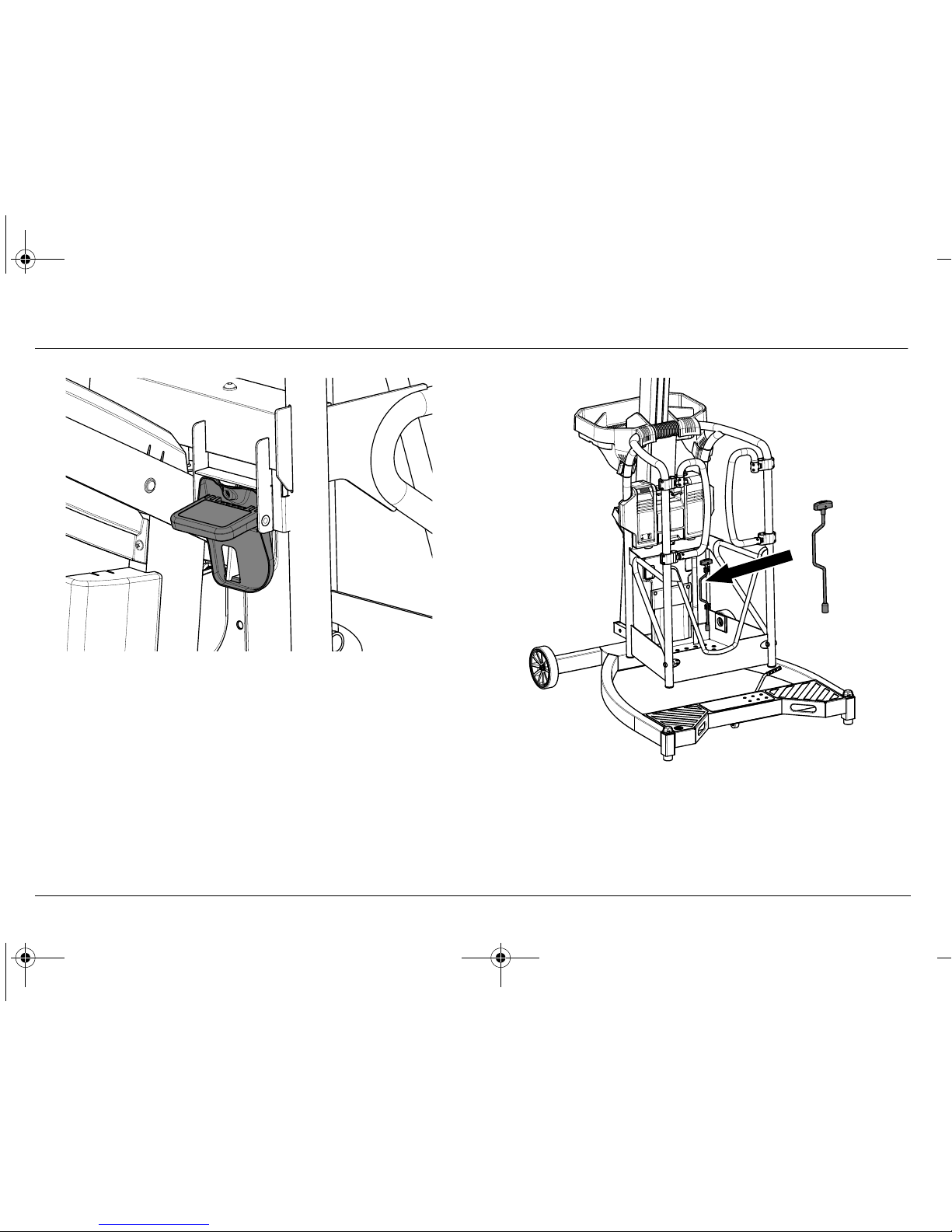
1. Remove the cordless drill and place it inside the platform. If the optional powerpack is installed, remove it
and place it sideways against the back panel in the platform (see Figure 4-1.).
2. Remove the manual descent crank from the mounting
clips inside the platform.
3. Engage the hexagon at the top of the driveshaft with the
socket end of the manual crank.
4. Push down on top of the handle to disengage the driveshaft lock and wind anti clockwise until the platform
comes to rest against the stops on the base.
Page 50

SECTION 4 - EMERGENCY PROCEDURES
1001070451 LIFTPOD by JLG 1-877-254-3876
4-2 www.liftpod.com 1-877-2-LIFTPOD
Operator Unable to Control Machine
If the platform operator is pinned, trapped or unable to operate or
control the machine other personnel should operate the machine
from ground using the manual descent crank on the lower facing
shaft stub.
Figure 4-1. Manual descent crank operation from
inside platform
Figure 4-2. Manual descent crank operation from
outside platform
Shaft Stub
FS.book Page 2 Wednesday, February 11, 2009 11:54 AM
Page 51

SECTION 4 - EMERGENCY PROCEDURES
1-877-254-3876 LIFTPOD by JLG 1001070451
1-877-2-LIFTPOD www.liftpod.com 4-3
NOTICE
IF THE OPTIONAL POWERPACK IS NOT INSTALLED, USE THE LANYARD
IN THE PLATFORM TO SECURE THE DRIVESHAFT IN A DEPRESSED
(PUSHED-IN) POSITION, RELEASING THE DRIVE INTERLOCK.
DO NOT ACTIVATE THE POWERPACK WHILE THE MANUAL DESCENT
CRANK IS ATTACHED.
Platform Caught Overhead
If the platform becomes jammed or snagged in overhead structures or equipment, rescue the platform occupant prior to freeing
the machine.
Rescue equipment can be used to remove the platform occupant.
Cranes and forklifts can be used to stabilize motion of the
machine.
Figure 4-3. Releasing the drive interlock using the
lanyard
Page 52

SECTION 4 - EMERGENCY PROCEDURES
1001070451 LIFTPOD by JLG 1-877-254-3876
4-4 www.liftpod.com 1-877-2-LIFTPOD
Rope Failure
The carriage and platform are elevated by two ropes.
Single Rope Failure
If one of the ropes fails while the platform is elevated, the other
rope will allow safe descent.
Upon failure of one of the ropes, immediately lower the platform.
Inform other personnel that the machine is out of service. Disassemble and clearly label the machine as being out of service. Contact your nearest Authorized JLG Service Center to arrange rope
replacement.
DO NOT ELEVATE PLATFORM WHEN IT IS ONLY SUPPORTED BY A SINGLE ROPE.
ROPE REPLACEMENT SHALL ONLY BE CARRIED OUT BY AN AUTHORIZED JLG SERVICE CENTER.
Double Rope Failure
If both ropes fail while the platform is elevated, the emergency
brake will activate automatically, locking the carriage to the mast.
In this condition the manual descent crank cannot be used to
lower the platform.
Operator elevated in Platform - Platform will not lower
If the operator cannot lower the platform to the support surface
call for help. The operator should then be safely removed from the
platform using suitable equipment.
DO NOT CLIMB OUT OF THE PLATFORM WHILE ELEVATED. THIS MAY
AFFECT THE MACHINE'S BALANCE, CAUSING IT TO TIP OVER. ONLY
EXIT THE PLATFORM VIA THE PLATFORM GATES. DO NOT ATTEMPT TO
CLIMB DOWN MAST.
FS.book Page 4 Wednesday, February 11, 2009 11:54 AM
Page 53

SECTION 4 - EMERGENCY PROCEDURES
1-877-254-3876 LIFTPOD by JLG 1001070451
1-877-2-LIFTPOD www.liftpod.com 4-5
4.2 INCIDENT NOTIFICATION
JLG Industries, Inc. must be notified immediately of any incident
involving a JLG product. Even if no injury or property damage is
evident, the factory should be contacted by telephone and provided with all necessary details.
Product Safety and Reliability Department
JLG Industries, Inc.
13244 Fountainhead Plaza
Hagerstown, MD 21742
USA
In USA:
Toll Free: 877-JLG-SAFE (877-554-7233)
Outside USA:
Phone: 717-485-6591
E-mail: ProductSafety@JLG.com
Failure to notify the manufacturer of an incident involving a JLG
Liftpod product within 48 hours of such an occurrence may void
any warranty consideration on that particular machine.
NOTICE
FOLLOWING ANY ACCIDENT, THOROUGHLY INSPECT THE MACHINE
AND TEST ALL FUNCTIONS. DO NOT ELEVATE PLATFORM UNTIL YOU
ARE SURE THAT ALL DAMAGE HAS BEEN REPAIRED IF REQUIRED, AND
THAT ALL CONTROLS ARE OPERATING CORRECTLY.
Page 54

SECTION 4 - EMERGENCY PROCEDURES
1001070451 LIFTPOD by JLG 1-877-254-3876
4-6 www.liftpod.com 1-877-2-LIFTPOD
This page intentionally left blank.
FS.book Page 6 Wednesday, February 11, 2009 11:54 AM
Page 55

SECTION 5 - GENERAL SPECIFICATIONS
1-877-254-3876 LIFTPOD by JLG 1001070451
1-877-2-LIFTPOD www.liftpod.com 5-1
SECTION 5. GENERAL SPECIFICATIONS
5.1 Introduction
This section of the manual provides operating specifications and
information necessary for proper maintenance of this machine.
5.2 Decal Installation
No. ANSI JLG Part Number
Replacement Decal Kit,
BASE, ANSI
100 107 1564
A1 Cr ushing Hazard-ANSI 100 107 0306
A2 Bubble Level-ANSI 100 107 0413
A3 Base Cr ush Hazard-ANSI 100 107 0438
A4 Step Plate Decal 100 107 0280
A5 General Brand 100 107 0281
A6 Max Wheel Load-ANSI 100 107 0310
A7 Barcode Base 100 107 0418
Replacement Decal Kit,
MAST/CARRIAGE, ANSI
100 107 1253
B1 Patent 100 107 0307
B2 Manual Descent-ANSI 100 107 0309
B3 Manufacturer Nameplate-ANSI 100 107 0442
B4 Mast Cap Warning-ANSI 100 107 0432
B5
Sharp Object & Mast Disassembly
Combo-ANSI
100 107 0433
B6 Cowling Side Brand 100 107 0410
B7 General Brand 100 107 0281
B8 Barcode Carriage 100 107 0419
No. ANSI JLG Part Number
Page 56

SECTION 5 - GENERAL SPECIFICATIONS
1001070451 LIFTPOD by JLG 1-877-254-3876
5-2 www.liftpod.com 1-877-2-LIFTPOD
Replacement Decal Kit,
PLATFORM, ANSI
100 107 1356
C1 Capacity-ANSI 100 107 0441
C2 Electrocution-ANSI 100 107 0303
C3 Platform Warning Chevrons 100 107 0409
C4 Platform Latch Release 100 107 0429
C5 Dril l Instructions 100 107 0445
C6 Summar y-ANSI 100 107 0302
C7 Lanyard Location-Length-ANSI 100 107 0411
C8 FS Quickstar t Guide 100 107 0415
C9 Manual 100 107 0451
C10 Barcode Platform 100 107 0417
No. ANSI JLG Part Number
Replacement Decal Kit,
POWERPACK, ANSI
100 107 1602
D1 Powerpack Socket Warning 100 107 0400
D2 E-Stop 100 107 0401
D3 Powerpack Drive Directions 100 107 0403
D4 Powerpack Battery Test 100 107 0404
D5 Powerpack Front Main Housing 100 107 0405
D6 Powerpack Instructions 100 107 0406
D7 Batter y Charger Front 100 107 0407
D8 Batter y Latch Instructions 100 107 0416
D9 Batter y Warning 100 107 0440
D10 Fast Charger Back 100 107 0443
D11 Battery Charger Branding 100 107 0408
No. ANSI JLG Part Number
FS.book Page 2 Wednesday, February 11, 2009 11:54 AM
Page 57

SECTION 5 - GENERAL SPECIFICATIONS
1-877-254-3876 LIFTPOD by JLG 1001070451
1-877-2-LIFTPOD www.liftpod.com 5-3
Table 5-1. Decal Descriptions.
D12 General Brand 100 107 0281
D13 Barcode Powerpack 100 107 0420
D14 Barcode Charger 100 107 0421
Replacement Decal Kit,
ACCESSORY TRAY, ANSI
100 107 1358
E1 Tool Tray-ANSI 100 107 0425
No. ANSI JLG Part Number
Page 58

SECTION 5 - GENERAL SPECIFICATIONS
1001070451 LIFTPOD by JLG 1-877-254-3876
5-4 www.liftpod.com 1-877-2-LIFTPOD
Figure 5-1. Base Decal Installation - ANSI
A7.
A1.
A1.
A6.
A6.
A2.
A3.
A5.
A4.
FS.book Page 4 Wednesday, February 11, 2009 11:54 AM
Page 59

SECTION 5 - GENERAL SPECIFICATIONS
1-877-254-3876 LIFTPOD by JLG 1001070451
1-877-2-LIFTPOD www.liftpod.com 5-5
Figure 5-2. Carriage/Mast Decal Installation - ANSI
B1.
B3.
B2.
B8.
B4.
B5.
B6.
B7.
B7.
Page 60

SECTION 5 - GENERAL SPECIFICATIONS
1001070451 LIFTPOD by JLG 1-877-254-3876
5-6 www.liftpod.com 1-877-2-LIFTPOD
Figure 5-3. Platform Decal Installation - ANSI
C1.
C3.
C3.
C3.
C8.
C10.
E1.
C6.
C2.
C4.
C7.
C5.
C9.
FS.book Page 6 Wednesday, February 11, 2009 11:54 AM
Page 61

SECTION 5 - GENERAL SPECIFICATIONS
1-877-254-3876 LIFTPOD by JLG 1001070451
1-877-2-LIFTPOD www.liftpod.com 5-7
Figure 5-4. Powerpack Decal Installation - ANSI
D1.
D2.
D10.
D3.
D4.
D5.
D6.
D11.
D8.
D13.
D14.
D9.
D7.
D12.
D12.
Page 62

SECTION 5 - GENERAL SPECIFICATIONS
1001070451 LIFTPOD by JLG 1-877-254-3876
5-8 www.liftpod.com 1-877-2-LIFTPOD
5.3 General Specifications
Machine Specifications (assembled)
Table 5-2. Machine Specifications (assembled)
SPECIFICATION FS80
Gross Machine Weight: (without optional tool trayor powerpack) 64.8kg (142.9 lb.)
Machine Height: 2.97m (9 ft 9 in)
Maximum Platform Floor Height: 2.32m (7 ft 7 in)
Maximum Wind Speed: 12.5m/sec (30 mph)
Maximum Working Height: (typical person) 4.32m (14 ft 4 in)
Machine Overall Footprint: 1,250mm x 1,040mm (4 ft 1 in x 3 ft 5 in)
Rated Horizontal Force 110N (24 lb.)
FS.book Page 8 Wednesday, February 11, 2009 11:54 AM
Page 63

SECTION 5 - GENERAL SPECIFICATIONS
1-877-254-3876 LIFTPOD by JLG 1001070451
1-877-2-LIFTPOD www.liftpod.com 5-9
Optional Powerpack Electrical Specifications
Table 5-3. Optional Powerpack Electrical Specifications
SPECIFICATION FS80
Batteries - Powerpack: 28.8 Volts DC
Nominal Duty Cycle: 4 cycles per 15 minutes (reduces at high and low ambient temperature)
Battery Specifications: Battery Type Nickel Metal Hydride
Voltage 28.8 Volts DC
Amp Hour (AH) Rating 4.5 Ah
Weight 2.3kg (5 lb.)
Battery Fast Charger: Input: 110/240 Volts AC - 2.2A - 50/60 Hz
FC 100 107 1675 Output: 28.8 Volts DC - 2 .5A - w/Auto Charge Sensing Circuit
Page 64

SECTION 5 - GENERAL SPECIFICATIONS
1001070451 LIFTPOD by JLG 1-877-254-3876
5-10 www.liftpod.com 1-877-2-LIFTPOD
Platform Data
Table 5-4. Platform Data
SPECIFICATION FS80
Occupants: (Persons allowed in Platform) 1
P l a t f o r m C a p a c it y : ANSI/C.S.A.: 150kg (330 lb.)
FS.book Page 10 Wednesday, February 11, 2009 11:54 AM
Page 65

SECTION 5 - GENERAL SPECIFICATIONS
1-877-254-3876 LIFTPOD by JLG 1001070451
1-877-2-LIFTPOD www.liftpod.com 5-11
Machine Component Weights
Table 5-5. Machine Component Weights
Serial Number Locations
For machine component identification, serial number barcode
decals are affixed to the various modules. The barcodes are
located as indicated in Figure 5-1. to Figure 5-4.
SPECIFICATION FS80
Base Frame 27.9kg (61.5 lb.)
Carriage/Mast 22.2kg (48.9 lb.)
Platform 14.7kg (32.4 lb.)
Optional Powerpack (inc Battery) 8kg (17.6 lb.)
Optional Tool Tray 3.6kg (7.9 lb.)
Page 66

SECTION 5 - GENERAL SPECIFICATIONS
1001070451 LIFTPOD by JLG 1-877-254-3876
5-12 www.liftpod.com 1-877-2-LIFTPOD
This page intentionally left blank.
FS.book Page 12 Wednesday, February 11, 2009 11:54 AM
Page 67

SECTION 6 - SERVICE AND MAINTENANCE
1-877-254-3876 LIFTPOD by JLG 1001070451
1-877-2-LIFTPOD www.liftpod.com 6-1
SECTION 6. SERVICE AND MAINTENANCE
6.1 INTRODUCTION - MAINTENANCE SAFETY
PRECAUTIONS
General
This section contains the general safety precautions which must
be observed during maintenance of the aerial platform. It is
important that maintenance personnel pay strict attention to these
warnings and precautions to avoid possible injury to themselves
or others or damage to the equipment. A maintenance program
must be established by a competent person and must be followed
to ensure that the machine is safe to operate.
NOTICE
JLG MAY HAVE ISSUED SAFETY BULLETINS FOR YOUR JLG PRODUCT.
CONTACT JLG OR THE LOCAL AUTHORIZED JLG SERVICE CENTRE FOR
INFORMATION CONCERNING SAFETY RELATED BULLETINS WHICH MAY
HAVE BEEN ISSUED FOR YOUR JLG PRODUCT. ALL ITEMS REQUIRED
BY THE SAFETY RELATED BULLETINS MUST BE COMPLETED ON THE
AFFECTED JLG PRODUCT.
Due to continuous product improvement, JLG reserves the right to
make specification changes without prior notification. Contact JLG
for updated information.
MODIFICATION OF THE MACHINE WITHOUT CERTIFICATION BY A
RESPONSIBLE AUTHORITY THAT THE MACHINE IS AT LEAST AS SAFE
AS ORIGINALLY MANUFACTURED IS AN OHSA SAFETY VIOLATION.
Your safety, and that of others, is the first consideration when
engaging in the maintenance of equipment. Always be conscious
of moving parts and pinch points. Do not allow heavy objects to
rest in an unstable position. When raising a portion of the equipment, ensure that adequate support is provided.
SINCE THE MACHINE MANUFACTURER HAS NO DIRECT CONTROL OVER
THE FIELD INSPECTION AND MAINTENANCE, SAFETY IN THESE AREAS
IS THE RESPONSIBILITY OF THE OWNER/OPERATOR.
Page 68

SECTION 6 - SERVICE AND MAINTENANCE
1001070451 LIFTPOD by JLG 1-877-254-3876
6-2 www.liftpod.com 1-877-2-LIFTPOD
Maintenance Safety
FAILURE TO COMPLY WITH SAFETY PRECAUTIONS LISTED IN THIS
SECTION COULD RESULT IN MACHINE DAMAGE, PERSONNEL INJURY
OR DEATH AND IS A SAFETY VIOLATION.
• REMOVE ALL RINGS, WATCHES, AND JEWELRY WHEN
PERFORMING ANY MAINTENANCE.
• DO NOT WEAR LONG HAIR UNRESTRAINED, OR LOOSE
FITTING CLOTHING AND NECKTIES WHICH ARE APT TO
BECOME CAUGHT ON OR ENTANGLED IN EQUIPMENT.
• OBSERVE AND OBEY ALL DANGER, WARNING, CAUTION
AND OTHER INSTRUCTIONS ON MACHINE AND IN OPERATION, SAFETY, SERVICE & MAINTENANCE MANUAL.
• KEEP STANDING SURFACES AND HAND HOLDS FREE OF
OIL, GREASE, WATER, ETC.
• NEVER WORK UNDER AN ELEVATED PLATFORM UNTIL
PLATFORM HAS BEEN SAFELY RESTRAINED FROM ANY
MOVEMENT BY BLOCKING OR OVERHEAD SLING.
• BEFORE MAKING ADJUSTMENTS OR PERFORMING ANY
OTHER MAINTENANCE, SHUT OFF ALL POWER CONTROLS.
• KEEP ALL SUPPORT EQUIPMENT AND ATTACHMENTS
STOWED IN THEIR PROPER PLACE.
• USE ONLY APPROVED, NONFLAMMABLE CLEANING SOLVENTS.
FS.book Page 2 Wednesday, February 11, 2009 11:54 AM
Page 69

SECTION 6 - SERVICE AND MAINTENANCE
1-877-254-3876 LIFTPOD by JLG 1001070451
1-877-2-LIFTPOD www.liftpod.com 6-3
6.2 MACHINE PREPARATION, INSPECTION AND
MAINTENANCE
General
This section provides the necessary information needed by those
personnel that are responsible to place the machine in operation
readiness and maintain its safe operating condition. For maximum
service life and safe operation, ensure that all necessary inspection and maintenance has been completed before placing the
machine into service.
Preparation, Inspection, and Maintenance
It is important to establish and conform to a comprehensive
inspection and preventive maintenance program. Table 2-1 outlines the periodic machine inspection and maintenance recommended by JLG. Consult your national, regional, or local
regulations for further requirements for aerial work platforms. The
frequency of inspection and maintenance must be increased as
environment, severity and frequency of usage requires.
Pre-Start Inspection
It is the user's or operator's primary responsibility to perform a PreStart Inspection of the machine prior to use daily or at each
change of operator. Reference Section 2 in this manual for completion procedures for the Pre-Start Inspection.
The manual must be read in its entirety and understood prior to
performing the Pre-Start Inspection.
Frequent and Pre-Delivery Inspection
The Frequent Inspection and Pre-Delivery Inspection shall be performed by a competent person or a qualified mechanic.
The Frequent Inspection and Pre-Delivery Inspection procedures
are performed in the same manner, but at different times. The PreDelivery Inspection shall be performed prior to each sale, lease, or
rental delivery. The Frequent Inspection shall be accomplished for
each machine in service for 3 months; out of service for a period of
more than 3 months; or when purchased used. The frequency of
this inspection must be increased as environment, severity and
frequency of usage requires.
Reference the appropriate areas of this manual for servicing and
maintenance procedures.
Annual Machine Inspection
The Annual Machine Inspection must be performed by a competent person or a qualified mechanic on an annual basis, no later
than thirteen (13) months from the date of the prior Annual
Machine Inspection.
Reference the Service and Maintenance Sections of this Manual
and appropriate JLG inspection form for performance of this
inspection.
Page 70

SECTION 6 - SERVICE AND MAINTENANCE
1001070451 LIFTPOD by JLG 1-877-254-3876
6-4 www.liftpod.com 1-877-2-LIFTPOD
Reference the appropriate areas of this manual for servicing and
maintenance procedures.
5 Year Machine Inspection & Rope Replacement
The mast and carriage module must be inspected and the ropes
replaced by an Authorized JLG Service Center when:
• The rope is worn beyond specification (see Figure 2-4.);
• A rope is tangled, damaged or broken;
• When the machine has been in service for 5 years.
NOTICE
IT IS IMPORTANT THAT JLG HAS UPDATED OWNERSHIP INFORMATION
FOR EACH MACHINE COMPONENT. WHEN PERFORMING EACH ANNUAL
MACHINE INSPECTION, NOTIFY JLG OF THE CURRENT MACHINE COMPONENT OWNERSHIP.
Preventive Maintenance
In conjunction with the specified inspections, maintenance shall
be performed by a competent person such as a qualified JLG
equipment mechanic.
6.3 PREVENTIVE MAINTENANCE AND
INSPECTION SCHEDULE
The preventive maintenance and inspection checks are listed and
defined in the following table. This table is divided into two basic
parts, the "AREA" to be inspected and the "INTERVAL" at which the
inspection is to take place. Under the "AREA" portion of the table,
the various systems along with the components that make up that
system are listed. The "INTERVAL" portion of the table is divided
into four columns representing the various inspection time periods. The numbers listed within the interval column represent the
applicable inspection code for which that component is to be
checked.
The checks and services listed in this schedule are not intended to
replace any local or regional regulations that may pertain to this
type of equipment nor should the lists be considered as all inclusive. Variances in interval times may occur due to climate and/or
conditions and depending on the location and use of the machine.
FS.book Page 4 Wednesday, February 11, 2009 11:54 AM
Page 71

SECTION 6 - SERVICE AND MAINTENANCE
1-877-254-3876 LIFTPOD by JLG 1001070451
1-877-2-LIFTPOD www.liftpod.com 6-5
Inspection and Maintenance Codes:
1. Check for proper and secure installation
2. No gouges, excessive wear, or dents showing
3. Visually inspect for excessive wear, damage, cracks, or
distortion
4. Check for cracked or broken welds
5. Check area is clean and free of debris
6. Check for proper adjustment
7. Check proper operation
8. Check returns to neutral or "off" position when released
9. Check for signs of leakage
10. Check for wear and/or proper routing
11. Check for proper tolerances
12. Check proper and authorized components installed
13. Verify
14. Perform
15. Replace
16. Inspect per Service and Maintenance Manual
Area on Machine Interval
Pre-Start Inspection Pre-Delivery or Frequent
Inspection
Annual (Yearly) Inspection
5 Year Inspection
Prior to use each day; or
at each operator change
Prior to each sale, lease
or delivery; in ser vice for
3 months or more; or
purchased used
Actually no later than 13
months from the date of
the prior inspection
Addition item - When
rope worn or no more
than 5 years from first
use
Mast 1, 5, 1, 2, 5 1, 2, 3, 5
Mast Stump 3, 5 3, 4, 5 3, 4, 5
Rope 10, 16 10, 16 10, 16 15
Carriage 5 3, 5 1, 3, 4, 5, 7
Gearbox 3, 9 3, 9 1, 3, 9
Page 72

SECTION 6 - SERVICE AND MAINTENANCE
1001070451 LIFTPOD by JLG 1-877-254-3876
6-6 www.liftpod.com 1-877-2-LIFTPOD
Area on Machine Pre-Start Inspection Pre-Delivery or Frequent
Inspection
Annual (Yearly) Inspection
5 Year Inspection
Manual Descent Crank 1 1, 12 1, 3, 12
Carriage Rollers 3, 7 3, 7, 11
Platform 1, 5 1, 5 1, 3, 4, 5, 7
Platform Latch 1, 7 1, 3, 6, 7 1, 3, 6, 7
Platform Gates 1, 7 1, 3, 5, 7 1, 3, 5, 7
Lanyard Anchor 3, 4 3, 4
Base Frame 3, 4, 5 3, 4, 5 3, 4, 5
Adjustable Feet 1 1, 3, 7 1, 3, 7
Bubble Level 1, 7 1, 7 1, 7
Wheels 1, 3, 7 1, 3, 7 1, 3, 7
Powerpack (optional) 1, 3 1, 3, 7 1, 3, 7
Switches & Controls 1 1, 3, 7 1, 3, 7
Speed & Safety Triggers; Battery Charge Test Button 1, 8 1, 3, 7, 8 1, 3, 7, 8
FS.book Page 6 Wednesday, February 11, 2009 11:54 AM
Page 73

SECTION 6 - SERVICE AND MAINTENANCE
1-877-254-3876 LIFTPOD by JLG 1001070451
1-877-2-LIFTPOD www.liftpod.com 6-7
Table 6-1. Preventative Maintenance & Inspection Schedule
General Pre-Start Inspection Pre-Delivery or Frequent
Inspection
Annual (Yearly) Inspection
5 Year Inspection
Operator, Safety, Service & Maintenance Manual in
Storage Pouch
13 13 13
All Decals/Placards Installed, Secure & Legible 13 13 13
Machine Inspection or Rope Replacement Due 16 16 14, 15
No Unauthorized Modifications or Additions 13 13
All Relevant Safety Publications Incorporated 13 13
General Structural Conditio n and Welds 3, 4 3, 4
All Fasteners, Pins, Shields and Covers 1, 3
Function Test of all Systems 14 14 14
Paint and Appearance 2, 5 2, 5
Record Inspection Date in Log Book 14
Notify JLG of Machine Ownership 14 (delivery) 14
Page 74

SECTION 6 - SERVICE AND MAINTENANCE
1001070451 LIFTPOD by JLG 1-877-254-3876
6-8 www.liftpod.com 1-877-2-LIFTPOD
6.4 SERVICING AND MAINTENANCE
GUIDELINES
General
The following information is provided to assist you in the use and
application of service and maintenance procedures contained in
this chapter.
WHEN AN ABNORMAL CONDITION IS NOTED AND PROCEDURES CONTAINED HEREIN DO NOT SPECIFICALLY RELATE TO THE NOTED IRREGULARITY, WORK SHOULD BE STOPPED AND TECHNICALLY QUALIFIED
GUIDANCE OBTAINED BEFORE WORK IS RESUMED.
Safety and Workmanship
Your safety, and that of others, is the first consideration when
engaging in the maintenance of equipment. Always be conscious
of moving components and pinch points. Do not allow heavy
objects to rest in an unstable position. When raising a portion of
the equipment, ensure that adequate support is provided.
Cleanliness
The most important single item in preserving the long service life
of a machine is to keep dirt and foreign materials out of the vital
components. Precautions have been taken to safeguard against
this. However, these items must be maintained on a scheduled
basis in order to function properly.
DO NOT LUBRICATE THE MACHINE. ENSURE THAT THE MAST AND
EMERGENCY BRAKE ARE CLEAN AND FREE OF DEBRIS, OIL AND
GREASE.
Component Disassembly and Reassembly
When disassembling or reassembling a component, complete the
procedural steps in sequence. Do not partially disassemble or
assemble one part, then start on another. Always recheck your
work to assure that nothing has been overlooked. Do not make
any adjustments, other than those recommended, without obtaining proper approval.
FS.book Page 8 Wednesday, February 11, 2009 11:54 AM
Page 75

SECTION 6 - SERVICE AND MAINTENANCE
1-877-254-3876 LIFTPOD by JLG 1001070451
1-877-2-LIFTPOD www.liftpod.com 6-9
6.5 REPLACEMENT KITS OVERVIEW
The following details the various replacement kits that can be
ordered from your Authorized JLG Service Center.
Figure 6-1. Replacement Kits
2.
3.
1.
4.
5.
6.
9.
13.
16.
15.
14.
11.
10.
17.
12.
7.
18.
8.
19.
20.
21.
Page 76

SECTION 6 - SERVICE AND MAINTENANCE
1001070451 LIFTPOD by JLG 1-877-254-3876
6-10 www.liftpod.com 1-877-2-LIFTPOD
1. Mast Cap Kit (JLG Part No. 1001071255)
2. Quick Start Guide Kit (JLG Part No. 1001071355)
3. Powerpack Battery (JLG Part No. 1001071635)
4. Manual Pouch Kit (JLG Part No. 1001071354)
5. Gate Assembly Kit LH (JLG Part No. 1001071351)
6. Gate Assembly Kit RH (JLG Part No. 1001071352)
7. Powerpack (JLG Part No. 1001071730)
8. Manual Descent Crank Kit
(JLG Part No. 1001071353)
9. Adjustable Foot Kit (2 feet per kit)
(JLG Part No. 1001071562)
10. Base Castor Mechanism Kit (JLG service only)
(JLG Part No. 1001071566)
11. Swivel Castor Wheel Kit (JLG Part No. 1001071561)
12. Rope (JLG service only) (JLG Part No. 1001070257)
13. Accessory Tray Kit (JLG Part No. 1001071725)
14. Plastic Cowlings Kit (JLG Part No. 1001071250)
15. Carriage Handle Kit (JLG Part No. 1001071251)
16. Fixed Wheel Kit (2 wheels per kit)
(JLG Part No. 1001071560)
17. Level Bubble Kit (JLG Part No. 1001071563)
18. Lower Rear Roller Kit (JLG Part No. 1001071252)
19. Complete Base Kit (JLG Part No. 1001071567)
20. Complete Platform Kit (JLG Part No. 1001071328)
21. Complete Mast/Carriage Kit
(JLG Part No. 1001071256)
NOTE: Following items not pictured.
22. Fast Charger - 110V (JLG Part No. 1001071675)
23. AC Lead - 110V (JLG Part No. 1001071750)
24. Charger Wall Plate Kit (JLG Part No. 1001071695)
25. Powerpack Carry Case (JLG Part No. 1001071705)
NOTE: Following items not pictured. Refer to Table 5-1 and Fig-
ure 5-1. to Figure 5-4 for replacement decal positions.
26. Decal Kit, Base, ANSI (JLG Part No. 1001071564)
27. Decal Kit, Mast/Carriage, ANSI
(JLG Part No. 1001071253)
FS.book Page 10 Wednesday, February 11, 2009 11:54 AM
Page 77

SECTION 6 - SERVICE AND MAINTENANCE
1-877-254-3876 LIFTPOD by JLG 1001070451
1-877-2-LIFTPOD www.liftpod.com 6-11
28. Decal Kit, Platform, ANSI
(JLG Part No. 1001071356)
29. Decal Kit, Powerpack, ANSI
(JLG Part No. 1001071602)
30. Decal Kit, Accessory Tray, ANSI
(JLG Part No. 1001071358)
31. Drill Strap Kit (JLG Part No. 1001071361)
32. Drill Socket Kit (JLG Part No. 1001071362)
33. Replacement Manual (JLG Part No. 1001071360)
34. Replacement Pouch Rivets (JLG Part No. 1001071339)
35. CSA Kit (JLG Part No. 1001071338)
6.6 Decal Replacement
All decals must be mounted to the machine as specified and be
clearly legible.
Please see Figure 5-1. to Figure 5-4 and refer to Table 5-1. for
positions and JLG part numbers.
To replace a damaged decal, first remove it completely, without
damaging the underlying surface.
Remove any remaining adhesive with a suitable solvent. Test solvent on inconspicuous area first, to ensure it does not mark or
damage the underlying surface finish.
NOTICE
SURFACE DAMAGE COULD RESULT IN CORROSION AND STRUCTURAL
DAMAGE.
Before applying new decal, ensure the surface is clean and dry.
Remove backing paper, apply decal along one edge then seat it
gently and evenly.
If there are any air bubbles, work them gently towards the edge
with a clean cloth.
Pressure sensitive adhesive reaches full strength after a several
days.
Page 78

SECTION 6 - SERVICE AND MAINTENANCE
1001070451 LIFTPOD by JLG 1-877-254-3876
6-12 www.liftpod.com 1-877-2-LIFTPOD
6.7 Mast Rope Inspection Procedure
NOTICE
MAST ROPES ARE TO BE INSPECTED EVERY THREE MONTHS OR MORE
FREQUENTLY AS DESCRIBED FOLLOWING.
The ropes should be inspected more frequently if used in a harsh
environment or high duty cycle applications. Inspection should be
more frequent as ropes approach the end of their useful lives. The
periodic inspection shall cover the entire length of the rope.
Only the surface of the ropes require inspection, do not attempt to
open the rope or remove any carriage covers. Any deterioration
resulting in any loss of original strength, such as described below,
shall be noted, and then a determination made if further use would
constitute a hazard.
Mast ropes must be replaced after machine has been in service
for five (5) years, regardless of rope condition, or sooner if conditions dictate. This must only be conducted by a Authorized JLG
Service Center.
Conditions such as the following shall be sufficient reason for
questioning continual use (of the rope) or increasing the frequency of inspection:
1. Rope Wear
Check rope is not frayed or damaged as per Figure 2-4. in the
Daily Walk-Around Inspection Section.
2. Rope Misaligned
With carriage lowered and the platform removed, check the following:
a. Ropes on drum should be neatly wound on adja-
cent grooves.
Figure 6-2. Drum view through inspection window
FS.book Page 12 Wednesday, February 11, 2009 11:54 AM
Page 79

SECTION 6 - SERVICE AND MAINTENANCE
1-877-254-3876 LIFTPOD by JLG 1001070451
1-877-2-LIFTPOD www.liftpod.com 6-13
b. Ropes must be parallel going into and through the
carriage, looking down the mast.
3. Rope Loose
In normal operation the rope is always taut and should never
come loose. Should the rope lose tension, say through incorrect
transport or storage, it must be corrected before next use.
Figure 6-3. Rope alignment through carriage
Incorrect, tangled - DO NOT USE
Correct - OK to use
Figure 6-4. Loose rope being re-tensioned
Page 80

SECTION 6 - SERVICE AND MAINTENANCE
1001070451 LIFTPOD by JLG 1-877-254-3876
6-14 www.liftpod.com 1-877-2-LIFTPOD
To correct a loose rope:
1. If carriage is not within 1m (3 ft) of the base of the mast
contact JLG. Otherwise assemble the mast onto the
base lifting via mast tube above carriage.
2. Check the rope is correctly on drum (Figure 6-2.).
3. Check rope is in correct location in carriage
(Figure 6-3.).
4. Connect the manual descent handle directly to the carriage drive shaft (Figure 6-4.). Press down on crank and
simultaneously rotate clockwise. You will hear a ratcheting noise and the drum will wind up the slack rope.
5. Re-check proper rope alignment (Figure 6-2. and Figure
6-3.). Both ropes must be tight. If ropes are not tight,
contact an Authorized JLG Service Center.
6. Install platform and cordless drill (or optional powerpack). Use applicable safety precautions to enter the
platform safely. Raise the platform 50mm (2 inch) to
reset the emergency brake and then lower the platform
to bottom of travel.
7. Perform all pre-operation checks before further use.
Also, remove platform and re-check rope alignment per
Figure 6-2. and Figure 6-3. after first elevation - which
should be no higher than 1m (3 ft). Ensure both ropes
are tight and remain so at all times.
FS.book Page 14 Wednesday, February 11, 2009 11:54 AM
Page 81

SECTION 7 - TROUBLESHOOTING
1-877-254-3876 LIFTPOD by JLG 1001070451
1-877-2-LIFTPOD www.liftpod.com 7-1
SECTION 7. TROUBLESHOOTING
7.1 GENERAL
This section contains troubleshooting information to be used for
locating and correcting most of the operating problems which
may develop in the aerial platform. If a problem should develop
which is not presented in this section or which is not corrected by
listed corrective actions, technically qualified guidance should be
obtained before proceeding with any maintenance.
Troubleshooting Information
The troubleshooting procedures applicable to the product are
listed and defined in Table 7-1, Troubleshooting (below).
Each malfunction within an individual group or system is followed
by a listing of probably causes which will enable determination of
the applicable remedial action. The probable causes and the
remedial action should, where possible, be checked in the order
listed in the tables.
It should be noted that there is no substitute for a thorough knowledge of the equipment and related systems.
It should be recognised that the majority of the problems arising in
the machine will be centred in the power system. For this reason,
every effort has been made to ensure that all likely problems in
these areas are given the fullest possible treatment. In the remaining machine groups, only those problems which are symptomatic
of greater problems which have more than one probable cause
and remedy are included. This means that problems for which the
probable cause and remedy may be immediately obvious are not
listed in this section.
TROUBLE PROBABLE CAUSE REMEDY
Machine does not assemble properly
Improper alignment on assembly Check each component and assembly alignment is correct.
Platform not fully engaged Check alignment and slide parts on until platform latch is properly engaged.
Page 82

SECTION 7 - TROUBLESHOOTING
1001070451 LIFTPOD by JLG 1-877-254-3876
7-2 www.liftpod.com 1-877-2-LIFTPOD
Powerpack (optional) motor does not start
Emergency stop button is engaged (PUSHED
IN) on powerpack
Disengage emergency stop button until it pops up (TURN CLOCKWISE).
Direction selector or enable trigger or speed
control trigger not activated
Select 'UP' on direction selector, then activate both the enable trigger and speed
control continuously for operation.
Battery not installed or no charge Properly install charged battery in powerpack.
Motor has overheated Wait until motor cools. The temperature cutout resets itself automatically.
Alternatively use manual descent procedure to lower platform (Section 4.1).
Platform does not lift up from bottom of travel - motor starts
Driveshaft interlock is engaged Push cordless drill on driveshaft down fir mly to disengage driveshaft safety inter-
lock.
(If using powerpack) Powerpack driveshaft not
engaged
Check powerpack is correctly fitted to platform, latch is down and drive shaft is
connected to carriage drive shaft.
Emergency brake not released from carriage
lock down latch position
E ns u re a l oa d gr e at er t ha n 5 0 kg (1 1 0 l b s .) i s i n t he p la t fo r m (1 p er s on ) a n d l if t i ng
ropes are tight. If latch has not released, attempt to lower the loaded platform
slightly then try again to lift up.
TROUBLE PROBABLE CAUSE REMEDY
FS.book Page 2 Wednesday, February 11, 2009 11:54 AM
Page 83

SECTION 7 - TROUBLESHOOTING
1-877-254-3876 LIFTPOD by JLG 1001070451
1-877-2-LIFTPOD www.liftpod.com 7-3
Platform will not move when in elevated position - motor starts
Driveshaft interlock is engaged Push cordless drill on driveshaf t down firmly to disengage driveshaft safety inter-
lock.
(If using powerpack) Powerpack shaft not
engaged
Check powerpack charged and in correctly fitted and is fully down and latched
down.
Drive shaft malfunction Lower platform using manual descent procedure (see Section 4.1). Refer to
Authorized JLG Service Center.
Ropes are loose (ropes must never be loose)
Machine was disassembled without platform
being fully lowered to engage the carriage lock
down latch. Carriage then moved up the mast
loosening the ropes
I f c a r ri a ge i s no t wi t hi n 1 m ( 3 f t) o f t h e base of the mast contact Authorized JLG
Service Center. Otherwise follow rope re-tensioning procedure detailed in Section
6.7, point 3. Ensure both ropes are tight and remain so at all times.
Machine does not wheel properly
Retractable Swivel Castor is not properly
deployed
W i t h n o l o a d i n t he p l a t f o r m o r o n t h e b a s e - lift the castor deploy handle on front of
base, adjacent to platform gate. Castor should deploy and lift front of machine off
adjustable feet to allow machine to roll easily on rear wheels and front castor.
Castor is damaged Replace castor.
TROUBLE PROBABLE CAUSE REMEDY
Page 84

SECTION 7 - TROUBLESHOOTING
1001070451 LIFTPOD by JLG 1-877-254-3876
7-4 www.liftpod.com 1-877-2-LIFTPOD
Table 7-1. Troubleshooting
Base will not level (DO NOT ELEVATE UNLESS BASE FIRM AND LEVEL)
C as t or d e pl o ye d W it h n o l o ad i n p l a tf o rm a nd pe o ple clear of adjustable feet - exert approximately
25kg pressure onto front of base. Castor should retract. Adjustable feet should
then be able to be used to level the machine on slopes less than 2 degrees front to
back. Do not use the machine on any side slope.
Machine rocks slightly side to side
Suppor t surface is not level Only use the machine on firm and level surfaces.
Adjustable feet are not BOTH in contact with
suppor ting surface
Adjust the feet so that BOTH feet are in firm contact with suppor ting surface AND
the machine is level.
Ropes are worn or a rope is broken or machine is 5 years old or machine has been in service for 5 years since previous service
Damage or wear or machine is 5 years old Deliver unit to an Authorized JLG Service Center for replacement.
Platform will not lift full rated load
Battery not fully charged Charge or replace battery.
Overload clutch is slipping Contact Authorized JLG Service Center.
TROUBLE PROBABLE CAUSE REMEDY
FS.book Page 4 Wednesday, February 11, 2009 11:54 AM
Page 85

This page intentionally left blank.
Page 86

JLG Worldwide Locations
JLG Industries (UK)
Unit 12, Southside
Bredbury Park Industrial Estate
Bredbury
Stockport
SK6 2sP
England
Phone: (44) 870 200 7700
Fax: (44) 870 200 7711
JLG Industries (Europe)
Kilmartin Place,
Tannochside Park
Uddingston G71 5PH
Scotland
Phone: (44) 1 698 811005
Fax: (44) 1 698 811055
JLG Industries (Australia)
P.O. Box 5119
11 Bolwarra Road
Port Macquarie
N.S.W. 2444
Australia
Phone: (61) 2 65 811111
Fax: (61) 2 65 810122
JLG Industries (Pty) Ltd.
Unit 1, 24 Industrial Complex
Herman Street
Meadowdale
Germiston
South Africa
Phone: (27) 11 453 1334
Fax: (27) 11 453 1342
JLG Europe B.V.
Transpolis Building
Polarisavenue 63
2132 JH HOOFDORP
The Netherlands
Phone: (31) 23 565 5665
Fax: (31) 23 557 2493
JLG Latino Americana Ltda.
Rua Eng. Carlos Stevenson,
80-Suite 71
13092-310 Campinas-SP
Brazil
Phone: (55) 19 3295 0407
Fax: (55) 19 3295 1025
JLG Polska
UI. Krolewska
00-060 Warsawa
Poland
Phone: (48) 91 4320 245
Fax: (48) 91 4358 200
JLG Industries (Sweden)
Enkopingsvagen 150
Box 704
SE - 175 27 Jarfalla
Sweden
Phone: (46) 8 506 59500
Fax: (46) 8 506 59534
JLG Deutschland GmbH
Max Planck Strasse 21
D-27721 Ritterhude/lhlpohl
Bei Bremen
Germany
Phone: (49) 421 693 500
Fax: (49) 421 693 5035
JLG Industries (Italia)
Via Po. 22
20010 Pregnana Milanese - MI
Italy
Phone: (39) 02 9359 5210
Fax: (39) 02 9359 5845
Plataformas Elevadoras
JLG Iberica, S.L.
Trapadella, 2
P.I. Castellbisbal Sur
08755 Castellbisbal
Spain
Phone: (34) 93 77 24700
Fax: (34) 93 77 11762
JLG Industries (Norge AS)
Sofeimyrveien 12
N-1412 Sofienyr
Norway
Phone: (47) 6682 2000
Fax: (47) 6682 2001
www.jlg.com
Corporate Office
JLG Industries, Inc.
13244 Fountainhead Plaza
Hagerstown, MD 21742-2678
USA
Phone 877-2-LIFTPOD (877-254-38763)
Fax (301) 745-3713
FS.book Page 2 Wednesday, February 11, 2009 11:54 AM
 Loading...