


JCB2059GES-PJCB2059GS1

GUIDE
JENN-A IR BOTTOM FREEZER R EFRIGERATOR
USER
USER
GUIDE
ABLE OF CONTENTS
T
Form No. B/10/02 Part No. 12642718 MCS No. 16021782 Printed in U.S.A.
©2002 Maytag Appliances Sales Co.
Introduction...........................................................................2
Important Safety Information............................................3
Installation Instructions...................................................4-9
How to Remove the Doors and Hinges .....................4
How to Reverse Refrigerator Door.............................5
How to Install and Remove Handles............................5
How to Replace the Doors and Hinges......................6
How to Install and Remove Panels...............................6
How to Remove and Install the Pullout Drawer.......7
How to Connect the Water Supply..............................8
How to Level Your Refrigerator ....................................9
Temperature Controls......................................................10
Fresh Food Features....................................................11-12
Water Dispenser.............................................................11
Interior Shelves................................................................11
Door Storage...................................................................11
Climate-Controlled Drawers .......................................12
Accessories .......................................................................12
Freezer Features ................................................................13
Automatic Ice Maker......................................................13
Drawers.............................................................................13
Accessories .......................................................................13
Water Filtration .................................................................14
Water Filter Data..............................................................15
Hints and Care ...................................................................16
Cleaning Instructions......................................................16
How to Remove and Replace Light Bulbs ................17
Food Storage Tips ..............................................................18
Food Storage Chart ..........................................................19
Normal Operating Sounds ..............................................20
Before You Call For Service ......................................21-22
Warranty..............................................................................23
Guide de L’Utilisateur.......................................................25
Guía del Usuario................................................................49

2
I
NTRODUCTION
Congratulations on the purchase of a Jenn-Air refrigerator!
We appreciate your purchase decision and feel confident you will be happy with this
appliance for years to come. For best results, please read this guide carefully.You will
find instructions on the proper operation and maintenance of your refrigerator.
Additionally, food storage information has been included for you.
Should you ever need our future assistance with your refrigerator,a complete model
and serial number recorded in the spaces below will be extremely helpful. These
numbers are found on a data plate inside the refrigerator compartment on the
upper surface.
Model Number ______________________________________________________
'P' Number __________________________________________________________
Serial Number________________________________________________________
Purchase Date _______________________________________________________
Dealer Name ________________________________________________________
Dealer Address _______________________________________________________
Dealer Phone ________________________________________________________
BEFORE
C
ALLING FOR
SERVICE...
If something seems unusual, please check the
“Before You Call For Service” section, which
is designed to help you solve basic problems
before calling a servicer.
WHAT IF THESE FEATURES
ARE
DIFFERENT FROM
MINE?
This book is intended to show the variety of
features that are available in the product
line. If your refrigerator does not have all the
options that are shown, many of these
options may be purchased by contacting the
Consumer Affairs Department. If you have
questions, write us (include your model
number and phone number) or call:
Maytag Appliances Sales Company
Attn: CAIR
®
Center
P.O. Box 2370
Cleveland,TN 37320-2370
U.S. and Canada 1-800-JENNAIR
(1-800-536-6247)
1-800-688-2080 (U.S.A.TTY for
hearing or speech impaired)
(Mon.-Fri., 8 am-8 pm Eastern Time)
Internet: http://www.maytag.com
CAUTION – Hazards or unsafe
practices which COULD result in
minor personal injury.
CAUTION:
3
I
MPORTANTSAFETYINFORMATION
WHAT
YOU NEED TO
KNOW
ABOUT SAFETY
INSTRUCTIONS
Warning and Important Safety
Instructions appearing in this manual are
not meant to cover all possible
conditions and situations that may occur.
Common sense, caution, and care must
be exercised when installing, maintaining,
or operating refrigerator.
Always contact your dealer, distributor,
service agent, or manufacturer about
problems or conditions you do not
understand.
S
AVE THESE INSTRUCTIONS
DANGER – Immediate hazards
which WILL result in severe
personal injury or death.
DANGER:
WARNING – Hazards or unsafe
practices which COULD result in
severe personal injury or death.
WARNING:
To reduce risk of fire, electric shock, serious injury or death when using your refrigerator, follow these basic
precautions, including the following:
WARNING:
To reduce risk of injury or death,
follow basic precautions, including
the following:
IMPORTANT: Child entrapment
and suffocation are not problems of the
past. Junked or abandoned refrigerators
are still dangerous – even if they sit out
for “just a few days.” If you are getting
rid of your old refrigerator, please
follow the instructions below to help
prevent accidents.
Before you throw away your old
refrigerator or freezer:
➢ Take off the doors.
➢ Leave the shelves in
place so children
may not easily climb
inside.
DANGER:
RECOGNIZE SAFETY
SYMBOLS,WORDS, LABELS
1. Read all instructions before using the refrigerator.
2. Observe all local codes and ordinances.
3. Be sure to follow grounding instructions.
4. Check with a qualified electrician if you are not sure this
appliance is properly grounded.
5. DO NOT ground to a gas line.
6. DO NOT ground to a cold-water pipe.
7. Refrigerator is designed to operate on a separate 103 to
126 volt, 15 amp., 60 cycle line. DO NOT modify plug on
power cord. If plug does not fit electrical outlet, have
proper outlet installed by a qualified electrician.
8. DO NOT use a two-prong adapter, extension cord or
power strip.
9. DO NOT remove warning tag from power cord.
10. DO NOT tamper with refrigerator controls.
11. DO NOT service or replace any part of refrigerator unless
specifically recommended in Owner’s Manual or published
user-repair instructions. DO NOT attempt service if
instructions are not understood or if they are beyond personal
skill level.
12. Always disconnect refrigerator from electrical supply
before attempting any service. Disconnect power cord by
grasping the plug, not the cord.
13. Install refrigerator according to Installation Instructions.All
connections for water, electrical power and grounding
must comply with local codes and be made by licensed
personnel when required.
14. Keep your refrigerator in good condition. Bumping or
dropping refrigerator can damage unit or cause unit to
malfunction or leak. If damage occurs, have refrigerator
checked by qualified service technician.
15. Replace worn power cords and/or loose plugs.
16. Always read and follow manufacturer’s storage and ideal
environment instructions for items being stored in
refrigerator.
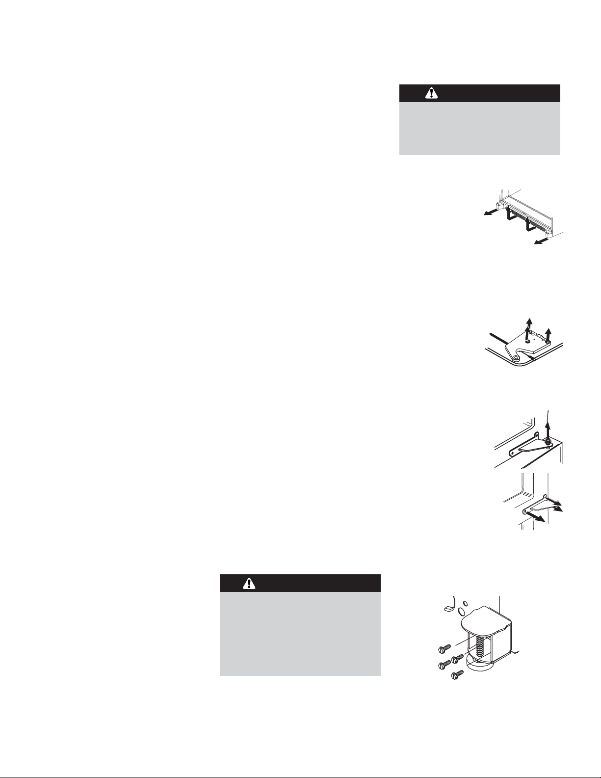
1. Unplug power cord from power
source.
2. Remove toe
grille and
bottom bracket
covers.
3. Remove the top trim of
fresh food door with Phillips
screwdriver.
• Retain screws and trim for
replacement.
4. Unscrew
5
⁄16" hex
head screws from
top hinge to
remove hinge.
• Retain all screws for later use.
5. Lift refrigerator door from center
hinge pin.
6. Remove center
hinge pin with a
5
⁄
16
"
hex nut driver.
• Retain hinge pin
for later use.
7. Remove Phillips
screws to remove
center hinge.
• Retain all screws for later use.
8. Remove both stabilizing brackets with
3
⁄
8" hex head driver.
• Retain screws for later use.
4
I
NSTALLATIONINSTRUCTIONS
These instructions were provided to aid
you in the installation of your refrigerator.
MEASURING THE
OPENING
A
1
⁄2
" of air space should be provided for
the back of the unit to allow for the
power cord and water line. When
installing your unit, measure carefully.
Subflooring or floor coverings (i.e.
carpet, tile, wood floors, rugs) may make
your opening smaller than anticipated.
Some clearance may be gained by using
the leveling procedure on page 9.
IMPORTANT: If unit is to be installed
into a recess where top of unit is
completely covered,use dimensions from
floor to top of hinge cap to verify proper
clearance.
T
RANSPORTING YOU
R
EFRIGERATOR
Follow these tips when moving the unit
to final location:
➢ NEVER transport unit on its side. If
an upright position is not possible, lay
unit on its back. Allow unit to sit
upright for approximately 30 minutes
prior to plugging unit in to assure oil
return to the compressor. Plugging
unit in immediately may cause damage
to internal parts.
➢ Use an appliance dolly when moving
unit. ALWAYS truck unit from its
side–NEVER from its front or back.
➢ Protect outside finish of unit during
transport by wrapping cabinet in
blankets or inserting padding between
the unit and dolly.
➢ Secure unit to dolly firmly with straps
or bungee cords. Thread straps
through handles when possible. DO
NOT overtighten. Overtightening
restraints may dent or damage
outside finish.
SELECTING THE
BEST
LOCATION
➢ Allow for a free flow of air through
the front base grille.
➢ Install the refrigerator where the
room temperature will not go below
55° F. With temperatures below 55° F,
the refrigerator will not run
frequently enough to maintain proper
temperature in the freezer.
➢ Locate the refrigerator away from
heat producing appliances such as the
range or dishwasher, heat vents and
direct sunlight.
➢ A minimum of
1
⁄2" clearance is required
at the back. Allow
1
⁄2" at the sides for
ease of installation. If refrigerator is
placed with the door hinge side against
a wall, you may want to allow
additional space.
➢ Use caution when installing the
refrigerator on vinyl or hardwood
floors so as not to mark or otherwise
damage the flooring. A piece of
plywood, a rug or other material
should be used to protect the floor
while positioning the refrigerator.
HOW TO REMOVE THE
DOOR AND HINGES
Some installations require door removal
to transport refrigerator to its final
location.
To remove drawer, see instructions on
page 7.
To avoid electrical shock which can
cause severe personal injury or death,
observe the following:
➢ Disconnect power to refrigerator
before removing doors. Connect
power only after replacing doors.
WARNING:
To avoid damage to walls and flooring,
protect soft vinyl or other flooring
with cardboard, rugs or other
protective material.
CAUTION:
5
HOW TO REVERSE
REFRIGERATOR DOOR
DOORS WITH TRIM AND
PANELS
1. Perform all steps listed in How to
Remove the Door and Hinges.
2. Perform removal steps listed in How
to Remove and Install Handles.
3. Transfer cabinet
plugs and screws to
opposite side of
cabinet.
4. Remove plugs with
flat blade of
screwdriver
wrapped in masking
tape.
5. Remove center mullion screws with
5
⁄16" hex head driver.
6. Locate door stop (B) and door cap (A)
on bottom edge of fresh food door.
Remove with a Phillips screwdriver.
• Retain all items for later replacement.
7. Remove side door trim (A) and
handle side trim (B) from door by
tapping bottom edges upward with a
soft rubber mallet.
• Trim will slide up approximately
3
⁄4"
and release from
door.
8. Rotate door panel
180° and tape in place.
9. Remove top door
extension with
1
⁄4" hex
head driver. Flip door
extension (A) so notched corner
turns in toward interior of door (B).
10. Retrieve alternate side door trim
shipped with refrigerator. Install trim
by aligning notches of trim with
metal mounting tabs on side of door.
• Slide trim down until piece locks
into place.
• Tap top of trim with rubber mallet
to insure snug fit.
• Repeat same procedure to install
handle side trim removed in step 7.
11. Replace bottom door cap (A)
removed in step 6. Install door stop
(B) on opposite side of door.
12. Remove tape from panels.
13. Proceed to next column to reinstall
handle.
To avoid possible injury and damage to
property, tape decorative panels (some
models) securely into place before
removing side door trim and handles.
WARNING:
%
$
$
%
%
$
$
%
Note:
When working directly on door, lay
the interior side of the door down
flat, nonabrasive surface. If using a
floor or table, prepare working
surface with rugs or towels to avoid
damage to door finish.
HOW TO
INSTALL AND
REMOVE
HANDLES
In some cases, handles may need to be
removed to transport unit through tight
spaces, reverse doors, or install panels.
Some models may come with handles
shipped separate from the refrigerator
door.
INSTALLING HANDLES
1. Retrieve handle from shipping
material (some models).
2. Locate handle
mounting posts on
face of door.
3. Position handle over mounting
posts.
4. Tighten set screws (A)
with a
3
⁄32" Allen
wrench
REMOVING HANDLES
1. Locate set screws in handle and
loosen set screws with a
3
⁄
32
" Allen
wrench.
2. Lift handle from handle mounting
posts to remove.
Note:
In cases of door
reversal, panel installation, or panel
removal, the mounting posts must be
removed. Use a
1
⁄4" hex head driver
to remove the post from the door.
$
I
NSTALLATIONINSTRUCTIONS
,
CONT
.
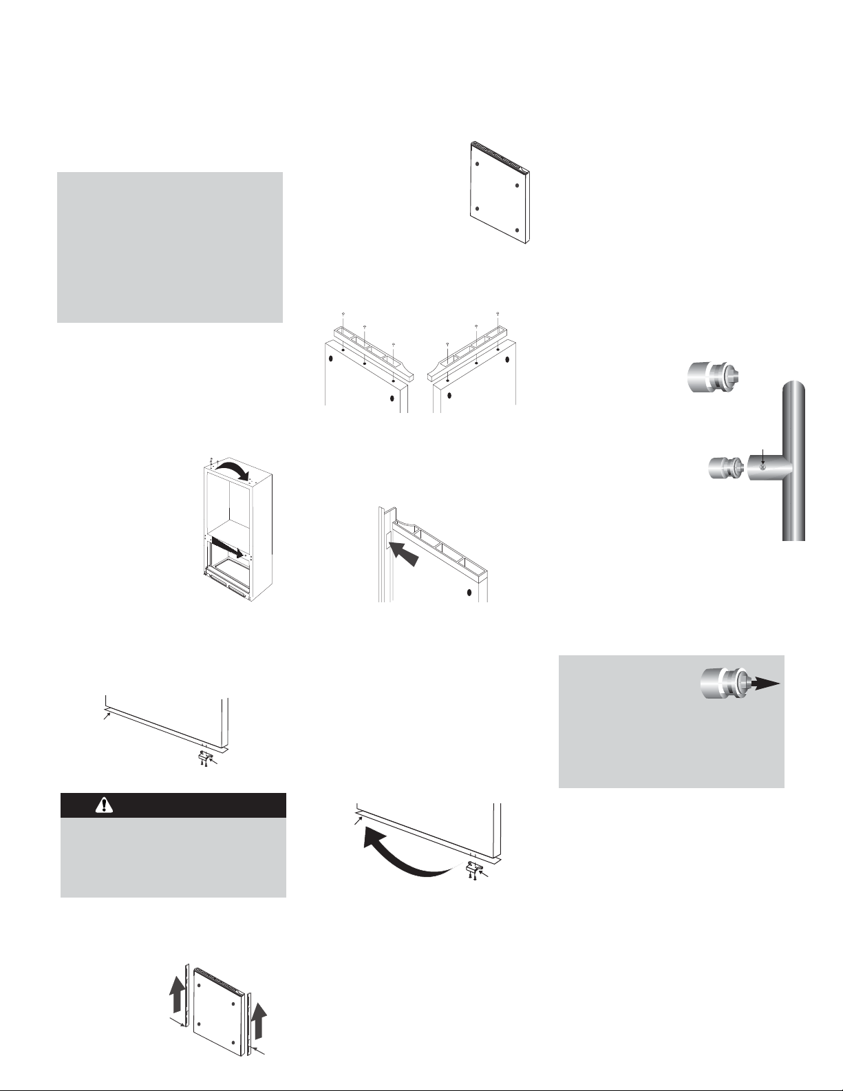
TO INSTALL PANELS:
1. Perform the handle removal
instructions in How to Install and
Remove the Handles, including
instructions to remove mounting
posts from door face.
2. Remove top door trim.
3. Remove handle side door trim.
4. Slide panel in the handle side of door,
by using grooves provided by bottom
door cap and side door trim.
5. Replace mounting posts, handles, and
trim.
TO REMOVE PANELS:
1. Perform the handle removal
instructions in How to Install and
Remove the Handles, including
instructions to remove mounting
posts from door face.
2. Remove top door trim.
3. Remove handle side door trim.
4. Slide panel out the handle side of
door.
HOW TO
REPLACE THE
DOOR AND
HINGES
1. Install center hinge with Phillips
screws.
2. Install stabilizing brackets with
3
⁄8" hex
head screws.
3. Replace center
hinge pin.
4. Place hinge side of
refrigerator door on center hinge pin.
5. While holding
refrigerator door
upright, tighten
down top hinge
with
5
⁄
16
" hex head
driver.
6. Install top door trim of fresh food
door with a Phillips screwdriver.
To avoid personal injury or property
damage, fresh food panel should not
weigh more than 30 lbs (14 kgs) and
freezer panel should not weigh more
than 15 lbs (7 kgs).
HOW TO
INSTALL AND
REMOVE
PANELS
(SOME MODELS)
WARNING:
6
Note:
If fresh food door is being reversed,
install alternate top hinge from
literature assembly.
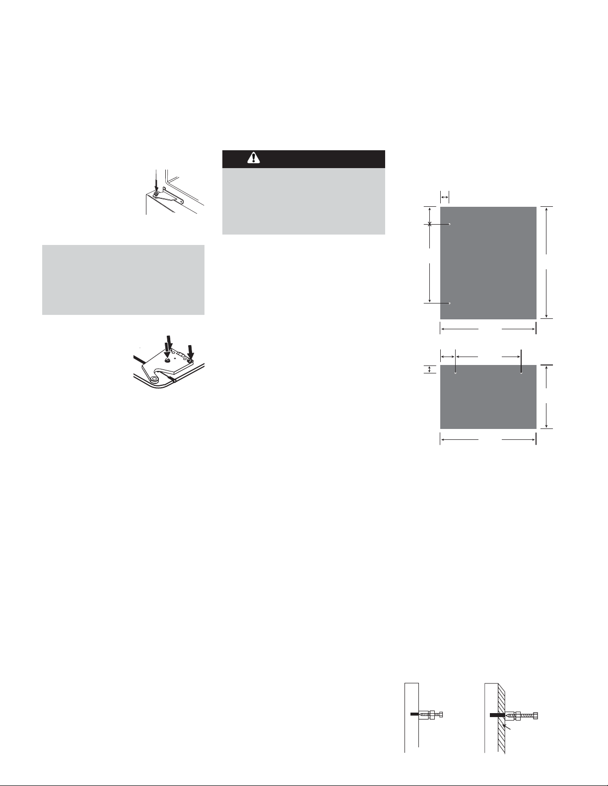
WHAT IF I AM
INSTALLING RAISED
PANELS?
Please see recommended dimensions for
paneling. All panel holes are
1
⁄4" diameter.
FP
FP
FP
FP
FP
FP
FP
FP
FP
FP
H
OW
DO
I MOUNT
H
ANDLES
ON
RAISED
P
ANELS?
The refrigerator is shipped with the
handle mounting posts attached to the
door with
1
⁄
4
" hex head screw that is
approximately 1
1
⁄2" long. This length is
necessary to safely secure the mounting
post to the door.
If handles are being mounted to a raised
surface, the factory supplied hex head
screws will have to be replaced with a
longer version. To determine how long
the replacement screw must be, add the
thickness of the raised panel to the 1
1
⁄2"
measurement. See example below.
1
1
⁄2" long 1⁄4" hex
head screw (factory
installed)
1" thick raised
panel = 2
1
⁄
2" long
1
⁄4" hex head screw
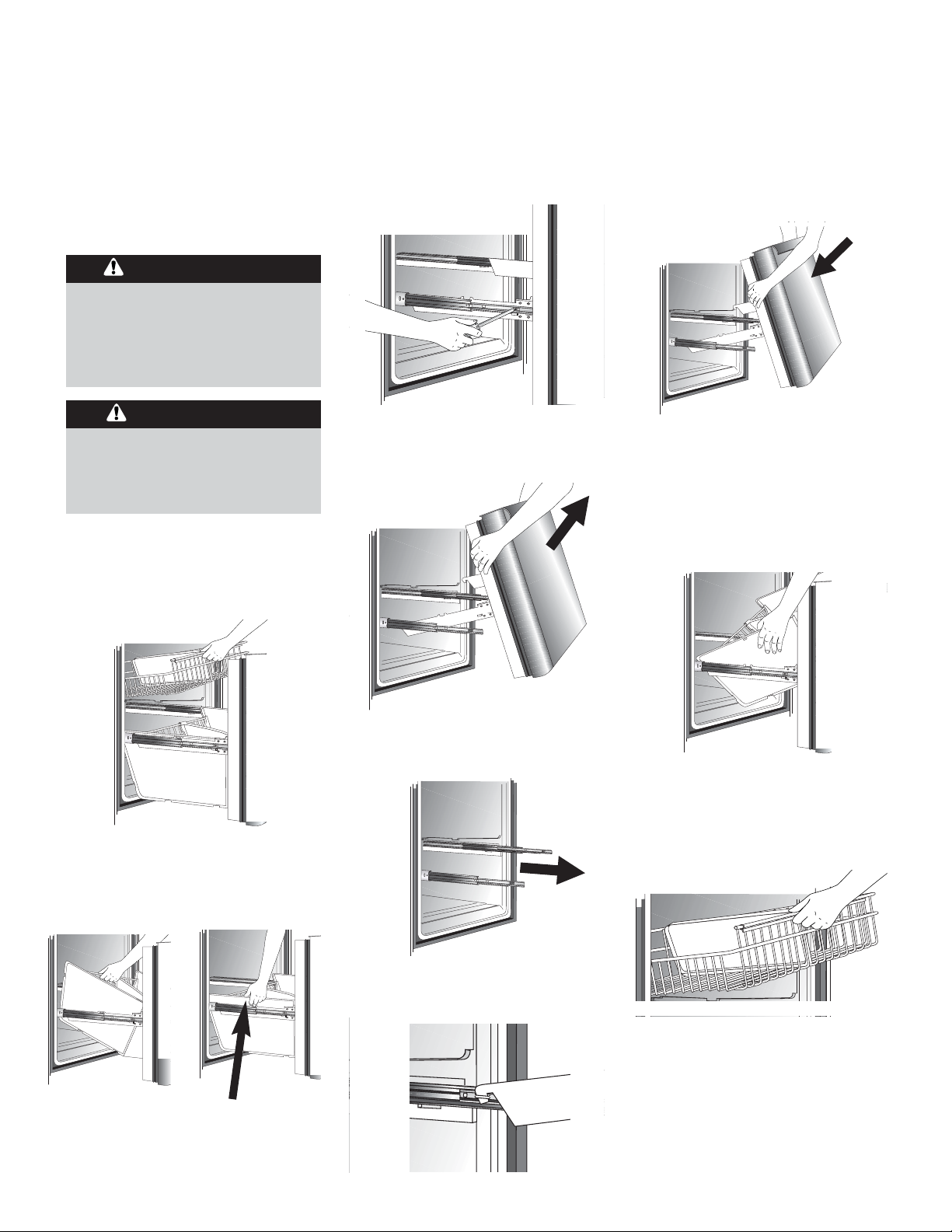
HOW TO
REMOVE AND
INSTALL THE
PULLOUT
DRAWER
To avoid electrical shock which can
cause severe personal injury or death,
disconnect power to refrigerator
before removing doors. After
replacing doors, connect power.
To avoid possible injury, product, or
property damage, you will need two
people to perform the following
instructions.
7
WARNING:
CAUTION:
3. Pull drawer open to full extension.
4. Remove Phillips screw from each side
of rail system. (Some models)
2. Remove lower basket by lifting basket
from rail system. (Model design may
vary.)
5. Lift top of door to unhook door
supports from rail system. Lift door
out to remove.
To install:
1. Pull both rails out to full extension.
5. With drawer pulled out to full
extension, insert lower basket by
aligning tabs on both sides of lower
basket with notches in rail assembly.
Verify that the basket sides are
hooked securely over the rails.
6. Slide upper basket into freezer. Make
sure that rear of basket hooks behind
rail catch.
3. Lower door into final position.
4. Replace and tighten Phillips screws
that were removed from each side of
rail system.
To remove:
1. Pull upper basket out to full extension
and lift out to remove.
2. While supporting door, hook door
supports into tabs located on inside
of rail.
Press Tab Here
(some models)
Or
I
NSTALLATIONINSTRUCTIONS
,
CONT
.
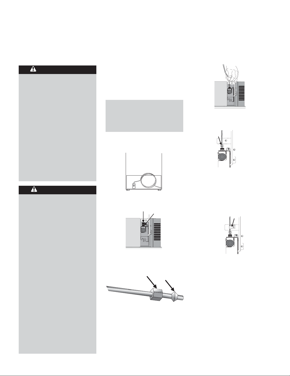
4. Place end of copper tubing into water
valve inlet port. Shape tubing slightly –
DO NOT KINK – so that tubing feeds
straight into inlet port.
5. Slide brass nut over sleeve and screw
nut into inlet port. Tighten nut with
wrench.
IMPORTANT: DO NOT overtighten.
Cross threading may occur.
6. Pull on tubing to confirm connection
is secure. Connect tubing to frame
with water tubing clamp (C) and turn
on water supply. Check for leaks and
correct, if present.
7. Monitor water connection for 24
hours. Correct leaks, if necessary.
HOW TO C
ONNECT
THE
WATER
SUPPLY
To reduce the risk of injury or
death, follow basic precautions,
including the following:
➢ Read all instructions before
installing device.
➢ DO NOT attempt installation if
instructions are not understood or
if they are beyond personal skill
level.
➢ Observe all local codes and
ordinances.
➢ DO NOT service device unless
specifically recommended in
owner’s manual or published userrepair instructions.
➢ Disconnect power to unit prior to
installing device.
To avoid property damage or
possible injury, follow basic
precautions, including the
following:
➢ Consult a plumber to connect
copper tubing to household
plumbing to assure compliance
with local codes and ordinances.
➢ Confirm water pressure to water
valve is between 20 and 100
pounds per square inch. If water
filter is installed, water pressure to
water valve must be a minimum of
35 pounds per square inch.
➢ DO NOT use a self-piercing, or
3
⁄16"
saddle valve! Both reduce water
flow, become clogged with time,
and may cause leaks if repair is
attempted.
➢ Tighten nuts by hand to prevent
cross threading. Finish tightening
nuts with pliers and wrenches. Do
not overtighten.
➢ Wait 24 hours before placing unit
into final position to check and
correct any water leaks.
MATERIALS NEEDED
➢
1
⁄4" outer diameter flexible copper
tubing
➢ Shut-off valve (requires a
1
⁄4" hole to
be drilled into water supply before
valve attachment)
➢ Adjustable wrench
➢
1
⁄4" hex nut driver
1. Create service loop with tubing using
care to avoid kinks in tubing.
2. Remove plastic cap from water valve
inlet port.
3. Place brass nut (A) and sleeve (B) on
copper tube end as illustrated.
$
%
8
WARNING:
CAUTION:
&
Note:
Add 8' to tubing length needed to
reach water supply for creation of
service loop.
 Loading...