


JB36CXFXLB00
Jenn-Air JB36CXFXLB00, JB36CXFXRB00, JB36PPFXLB00, JB36PPFXRB00, JB36SEFXLB00 Installation Guide
...
JENN-AIR_BOTTOMMOUNTBUILT-INREFRIGERATOR
CONGELADOR
ENLAPARTEINFERIORJENN-AIR_
REFRIGI_RATEURENCASTRI_AVECCONGI_LA'EUR
ENDESSOUSJENN-AII_
INSTALLATIONGUIDE
For questions about features, operation/performance, parts, accessories, or service, call:
1-800-JENNAIR (1-800-536-6247) or visit our website at www.jennair.com.
In Canada, call: 1-800-807-6777, or visit our website at www.jennair.ca.
MANUAL DEINSTALACION
Si tiene preguntas respecto alas caracteristicas, funcionamiento, rendimiento, partes, accesorios o servicio tecnico, Ilame al:
1-800-JENNAIR (1-800-536-6247) o visite nuestro sitio de internet: www.jennair.com.
En CanadA, Ilame al: 1-800-807-6777, o visite nuestro sitio de internet: www.jennair.ca.
GUIDED'INSTALLATION
Au Canada, pour assistance, installation ou service, composez le 1-800-807-6777 ou visitez notre site web & www.jennair.ca.
Table of Contents/[ndice/Table des matieres ...................................................................................... 2
_°JENN-AIRo
W10183782A
TABLEOF CONTENTS
REFRIGERATOR SAFETY ........................................................................... 3
36" MODELS ................................................................................................ 4
42" FRENCH DOOR MODELS .................................................................... 5
INSTALLATION REQUIREMENTS ............................................................. 6
Tools and Parts ......................................................................................... 6
Location Requirements ............................................................................. 6
Electrical Requirements ............................................................................ 7
Water Supply Requirements ..................................................................... 8
Tipping Radius .......................................................................................... 8
Product Dimensions ................................................................................. 9
Door Swing Dimensions ......................................................................... 10
Overlay Series Door Panel & Cabinetry Clearance
(36" [91.4 cm] Models) ............................................................................ 11
Overlay Series Door Panel & Cabinetry Clearance
(42" [106.7 cm] Models) .......................................................................... 13
Overlay Series Custom Panels ............................................................... 15
Custom Overlay Panel Dimensions ........................................................ 15
Euro-Style and Pro-Style ®Door Handle Kits .......................................... 17
Euro-Style and Pro-Style ®Custom Side Panels .................................... 17
Overlay Series Custom Side Panels ....................................................... 18
INSTALLATION INSTRUCTIONS ............................................................. 19
Unpack the Refrigerator ......................................................................... 19
Reduce Tipping Radius .......................................................................... 19
Move the Refrigerator into House .......................................................... 20
Install Anti-Tip Boards ............................................................................ 20
Connect the Water Supply ..................................................................... 21
Plug in Refrigerator ................................................................................. 22
Move Refrigerator to Final Location ....................................................... 22
Level and Align Refrigerator ................................................................... 22
Install Overlay Series Custom Panels .................................................... 23
Adjust Door(s) ......................................................................................... 24
Install Side Panel .................................................................................... 26
Install Base Grille .................................................................................... 27
Complete Installation .............................................................................. 27
Water System Preparation ..................................................................... 27
[NDICE
SEGURIDAD DEL REFRIGERADOR ........................................................ 28
MODELOS DE 36". .................................................................................... 29
MODELOS DE DOS PUERTAS CON CONGELADOR
EN LA PARTE INFERIOR, DE 42". ........................................................... 30
REQUlSlTOS DE INSTALAClON .............................................................. 31
Piezas y herramientas ............................................................................. 31
Requisitos de ubicaci6n ......................................................................... 31
Requisitos electricos ............................................................................... 32
Requisitos del suministro de agua ......................................................... 33
Arco de vuelco ........................................................................................ 33
Medidas del producto ............................................................................. 34
Medidas de oscilaci6n de lapuerta ........................................................ 35
Espacio para el panel de la puerta de la serie Overlay y
para los armarios (modelos de 36" [91,4 cm]) ....................................... 36
Espacio para el panel de la puerta de la serie Overlay
y para los armarios (modelos de 42" [106,7 cm]) ................................... 38
Paneles a la medida de la Serie Overlay ................................................ 40
Dimensiones del panel recubierto a la medida ...................................... 40
Juegos de manijas para puertas de estilo europeo y Pro-Style ®.......... 42
Paneles laterales a la medida para el estilo europeo y Pro-Style ®........ 42
Paneles laterales a la medida para la Serie Overlay .............................. 43
INSTRUCCIONES DE INSTALACION ...................................................... 44
Desempaque el refrigerador ................................................................... 44
C6mo reducir el arco de vuelco ............................................................. 45
C6mo hacer entrar el refrigerador en lacasa ........................................ 45
C6mo instalar los tableros antivuelco .................................................... 45
Conexi6n del suministro de agua ........................................................... 46
C6mo enchufar el refrigerador ............................................................... 47
C6mo mover el refrigerador a su ubicaci6n final ................................... 47
Nivelaci6n y alineamiento del refrigerador ............................................. 48
C6mo instalar los paneles a la medida para la Serie Overlay ............... 48
C6mo ajustar la(s) puerta(s) .................................................................... 50
C6mo instalar el panel lateral ................................................................. 52
C6mo instalar la rejilla de la base ........................................................... 52
C6mo terminar la instalaci6n .................................................................. 53
Preparaci6n del sistema de agua ........................................................... 53
TABLEDESMATIERES
SI_CURITI_ DU RI_FRIGI_RATEUR ........................................................... 54
MOD#LES DE 36". ..................................................................................... 55
MOD#LES AVEC PORTES A DOUBLE BATTANT DE 42". .................... 56
EXIGENCES D'INSTALLATION ................................................................ 57
Outillage et pieces .................................................................................. 57
Exigences d'emplacement ..................................................................... 57
Specifications 61ectriques ...................................................................... 58
Specifications de I'alimentation en eau.................................................. 59
Rayon de basculement ........................................................................... 59
Dimensions du produit ............................................................................ 60
Dimensions pour le pivotement des portes ........................................... 61
S6rie Overlay - Panneau de porte et placard -
dimensions et espace libre (modeles de 36" [91,4 cm]) ........................ 62
S6rie Overlay - Panneau de porte et placard -
dimensions et espace libre (modUles de 42" [106,7 cm]) ...................... 64
Panneaux personnalises de la s6rie Overlay .......................................... 66
Panneaux personnalises - Dimensions .................................................. 66
Ensembles de poignees de porte
style europeen et Pro-Style ®................................................................... 68
Panneaux lateraux personnalises
des style europ6en et Pro-Style ®............................................................ 68
Panneaux lat6raux personnalis_s de la serie Overlay ............................ 69
INSTRUCTIONS D'INSTALLATION ......................................................... 70
Deballage du refrigerateur ...................................................................... 70
Reduction du rayon de basculement ..................................................... 71
Faire entrer le refrig_rateur dans le domicile .......................................... 71
Installation de planches antibasculement .............................................. 71
Raccordement & la canalisation d'eau ................................................... 72
Brancher le r6frig6rateur ......................................................................... 73
Deplacement du r6frig_rateur a I'emplacement final ............................. 73
R6glage de I'aplomb et alignement du r6frig6rateur .............................. 74
Installation des panneaux personnalises de la serie Overlay ................ 74
Ajustement de la (des) porte(s) ............................................................... 76
Installation du panneau lat6ral ................................................................ 78
Installation de la grille de la base ........................................................... 78
Achever I'installation ............................................................................... 79
Preparation du syst_me d'eau ............................................................... 79
2
REFRIGERATORSAFETY
Your safety and the safety of others are very important.
We have provided many important safety messages in this manual and on your appliance. Always read and obey all safety
messages.
This is the safety alert symbol.
This symbol alerts you to potential hazards that can kill or hurt you and others.
All safety messages will follow the safety alert symbol and either the word "DANGER" or "WARNING."
These words mean:
You can be killed or seriously injured if you don't immediately
follow instructions.
You can be killed or seriously injured if you don't follow
instructions.
All safety messages will tell you what the potential hazard is, tell you how to reduce the chance of injury, and tell you what can
happen if the instructions are not followed.
Tip Over Hazard
Refrigerator is top heavy and tips easily when not
completely installed.
Keep doors taped closed until refrigerator is
completely installed.
Use two or more people to move and install
refrigerator.
Failure to do so can result in death or serious injury.
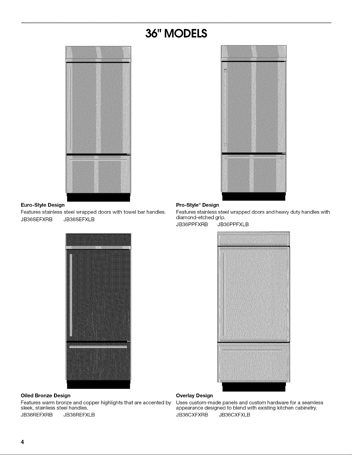
36"MODELS
Euro-Style Design
Features stainless steel wrapped doors with towel bar handles.
JB36SEFXRB JB36SEFXLB
Pro-Style s Design
Features stainless steel wrapped doors and heavy duty handles with
diamond-etched grip.
JB36PPFXRB JB36PPFXLB
Oiled Bronze Design
Features warm bronze and copper highlights that are accented by
sleek, stainless steel handles.
JB36REFXRB JB36REFXLB
Overlay Design
Uses custom-made panels and custom hardware for a seamless
appearance designed to blend with existing kitchen cabinetry.
JB36CXFXRB JB36CXFXLB
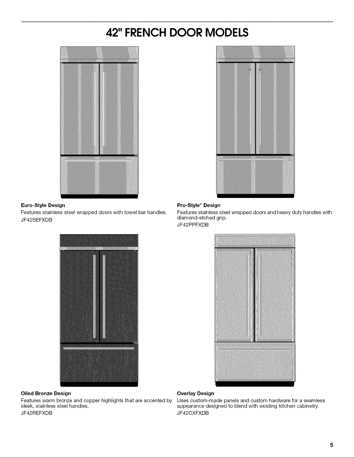
42" FRENCHDOOR MODELS
Euro-Style Design
Features stainless steel wrapped doors with towel bar handles.
JF42SEFXDB
Pro-Style s Design
Features stainless steel wrapped doors and heavy duty handles with
diamond-etched grip.
JF42PPFXDB
Oiled Bronze Design
Features warm bronze and copper highlights that are accented by
sleek, stainless steel handles.
JF42REFXDB
Overlay Design
Uses custom-made panels and custom hardware for a seamless
appearance designed to blend with existing kitchen cabinetry.
JF42CXFXDB
INSTALLATIONREQUIREMENTS
Isc nd
IMPORTANT:
• Installer: Leave Installation Instructions with the homeowner.
• Homeowner: Keep Installation Instructions for future
reference. Save these Installation Instructions for the local
electrical inspector's use.
TOOLS NEEDED:
Gather the required tools and parts before starting installation.
Read and follow the instructions provided with any tools listed
here.
• Cordless drill • Torx®tT15 and T27 screwdrivers
• Drill bits • 1V32"nut driver
• Two adjustable • 3/8",V4",and W' open-end
wrenches wrenches
• Phillips screwdriver • %2"Allen wrench
• Small level • V4" and 5Ae"socket drivers
• Appliance dolly • Tape measure
• Utility knife
PARTS NEEDED:
Six #8 x 3" (7.6 cm) wood screws (longer screws may be needed)
One or two 2" x 4" x 32" (5 cm x 10 cm x 81 cm) wood board(s)
Overlay Series: Make custom panels, or consult a qualified
cabinetmaker or carpenter to make the panels. See
"Installation Requirements" for more information.
Pro-Style ®and Euro-Style are shipped complete.
If you are connecting the water line directly to copper tubing
and not to a shutoff valve, you need a ferrule, a union, and a
V4"compression fitting.
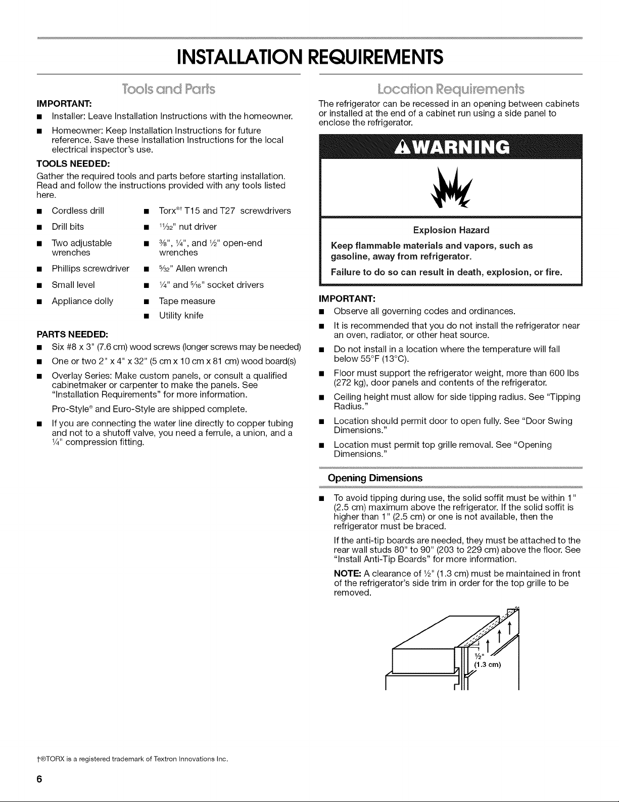
The refrigerator can be recessed in an opening between cabinets
or installed at the end of a cabinet run using a side panel to
enclose the refrigerator.
Explosion Hazard
Keep flammable materials and vapors, such as
gasoline, away from refrigerator.
Failure to do so can result in death, explosion, or fire.
IMPO RTANT:
• Observe all governing codes and ordinances.
• It is recommended that you do not install the refrigerator near
an oven, radiator, or other heat source.
• Do not install in a location where the temperature will fall
below 55°F (13°C).
• Floor must support the refrigerator weight, more than 600 Ibs
(272 kg), door panels and contents of the refrigerator.
• Ceiling height must allow for side tipping radius. See "Tipping
Radius."
• Location should permit door to open fully. See "Door Swing
Dimensions."
• Location must permit top grille removal. See "Opening
Dimensions."
Opening Dimensions
To avoid tipping during use, the solid soffit must be within 1"
(2.5 cm) maximum above the refrigerator. If the solid soffit is
higher than 1" (2.5 cm) or one is not available, then the
refrigerator must be braced.
If the anti-tip boards are needed, they must be attached to the
rear wall studs 80" to 90" (203 to 229 cm) above the floor. See
"Install Anti-Tip Boards" for more information.
NOTE: A clearance of W' (1.3 cm) must be maintained in front
of the refrigerator's side trim in order for the top grille to be
removed.
I"®TORX is a registered trademark of Textron Innovations Inc.
6
A grounded 3 prong electrical outlet should be placed within
4" (10.2 cm) of the right side cabinets or end panel. See
"Electrical Requirements" for additional information.
The water shutoff should be located in the base cabinet on
either side of the refrigerator or some other easily accessible
area. If the water shutoff valve is not in the cabinets, the
plumbing for the water line can come through the floor or the
back wall. See "Water Supply Requirements" for more specific
information.
0
831/2'' (212.1 cm) min.
843/4'' (215 cm) max.
to bottom of solid soffit
A
Width
(see chart following)
(10.2 cm)
77"
(196 cm)
6 ,I
(15.2 cm'
q--
(15.2 c
24"
(60.96 cm) min.
Model Width A (as shown above)
36 351/2"(90.2 cm)
42 411/2"(105.4 cm)
NOTE: Flooring under refrigerator must be at same level as the
room.
Electrical Shock Hazard
Plug into a grounded 3 prong outlet.
Do not remove ground prong.
Do not use an adapter.
Do not use an extension cord.
Failure to follow these instructions can result in death,
fire, or electrical shock.
Before you move your refrigerator into its final location, it is
important to make sure you have the proper electrical connection.
Recommended Grounding Method
A 115 Volt, 60 Hz., AC only, 15- or 20-amp fused, grounded
electrical supply is required. It is recommended that a separate
circuit serving only your refrigerator be provided. Use an outlet
that cannot be turned off by a switch. Do not use an
extension cord.
IMPORTANT: If this product is connected to a GFCI (Ground Fault
Circuit Interrupter) protected outlet, nuisance tripping of the
power supply may occur, resulting in loss of cooling. Food quality
and flavor may be affected. If nuisance tripping has occurred, and
if the condition of the food appears poor, dispose of it.
NOTE: Before performing any type of installation, cleaning, or
removing a light bulb, remove the top grille and turn the master
power switch to OFF or disconnect power at the circuit breaker
box.
When you are finished, turn ON the master power switch or
reconnect power at the circuit breaker box. Then reset the control
to the desired setting.
• p y
All installations must meet local plumbing code requirements.
The water shutoff should be located in the base cabinet on
either side of the refrigerator or some other easily accessible
area. The right-hand side is recommended. The access hole
through the cabinet must be within 1/2"(12.7 mm) of the rear
wall.
NOTE: If the water shutoff valve is in the back wall behind the
refrigerator, it must be at an angle so that the tube is not
kinked when the refrigerator is pushed into its final location.
+
1"
(2.54 cm)
24"
(60.96 cm) min.
6 ,I
(15.2 cm)
If the water shutoff valve is not in the cabinets, the plumbing
for the water line can come through the floor. A 1/2"(12.7 mm)
hole for plumbing should be drilled at least 6" (15.2 cm) from
the right or left hand side cabinet or panel. On the floor, the
hole should be no more than 1" (2.54 cm) away from the back
wall. See "Connect the Water Supply."
If additional tubing is needed, use copper tubing and check
for leaks. Install the copper tubing only in areas where the
household temperatures will remain above freezing.
Do not use a piercing-type or 34e"(4.76 mm) saddle valve
which reduces water flow and clogs more easily.
NOTE: Your refrigerator dealer has a kit available with a 1/4"
(6.35 mm) saddle-type shutoff valve, a union, and copper
tubing. Before purchasing, make sure a saddle-type valve
complies with your local plumbing codes.
Water Pressure
A cold water supply with water pressure between 30 and 120 psi
(207 and 827 kPa) is required to operate the water dispenser and
ice maker. Ifyou have questions about your water pressure, call a
licensed, qualified plumber.
Reverse Osmosis Water Supply
IMPORTANT: The pressure of the water supply coming out of a
reverse osmosis system going to the water inlet valve of the
refrigerator needs to be between 30 and 120 psi
(207 and 827 kPa).
If a reverse osmosis water filtration system is connected to your
cold water supply, the water pressure to the reverse osmosis
system needs to be a minimum of 40 to 60 psi (276 to 414 kPa).
If the water pressure to the reverse osmosis system is less than
40 to 60 psi (276 to 414 kPa):
• Check to see whether the sediment filter in the reverse
osmosis system is blocked. Replace the filter if necessary.
• Allow the storage tank on the reverse osmosis system to refill
after heavy usage.
• If your refrigerator has a water filter cartridge, it may further
reduce the water pressure when used in conjunction with a
reverse osmosis system. Remove the water filter cartridge.
If you have questions about your water pressure, call a licensed,
qualified plumber.
_ k,_J _,_,s;5_
Be sure there is adequate ceiling height to stand the refrigerator
upright when it is moved into place.
• The dolly wheel height must be added to the tipping radius
when a dolly is used.
• If needed, the tipping radius can be reduced. See "Reduce
Tipping Radius."
Side Tipping Radius (36" [91.4 cm] Models)
/
/
/
/
/
/
/
/
//
1
/
/
/
/
/
f
(
(
901/2''
A ......
_ -.q{-_ (229.9 cm)
A. Tip this side only.
8

SideTippingRadius(42"[106.7cm]Models)
/JJf [
/
/
/
/
/
//
//
//
/
/
/
I
/
/
93"
_-_ (236.2 cm)
.....,
A. Tip this side only.
Side View
The power cord is 84" (213 cm) long.
The water line attached to the back of the refrigerator is 5 ft
(1.5 m) long. Height dimensions are shown with leveling legs
extended 1/8"(3 mm) below the rollers.
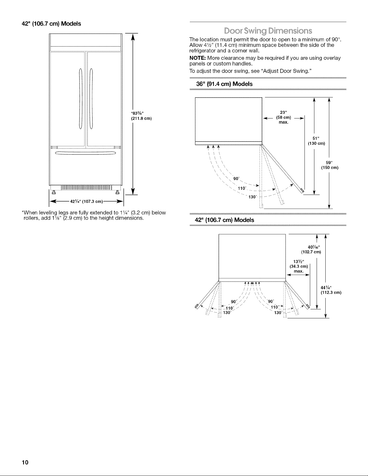
"833/8''
(211.8 cm)
T
231/2''
(59.7 cm)
84" (213.4 cm)
Power Cord
Series
Overlay Design
Euro-Style or Pro-Style ®Design
*When leveling legs are fully extended to 1V4"(3.2 cm) below
rollers, add 1V8"(2.9 cm) to the height dimensions.
"31/2'' (6.9 cm)
A
251/8"(63.8 cm)
253/8'' (64.5 cm)
TopView
36" (91.4 cm) Models
351/4"
(89.5 cm)
T
25%"
(64.5 cm)
NOTE: Add up to 21Vie'' (6.74 cm) for the handles.
42" (106.7 cm) Models
411/4" _1
<-_ (105cm) _ I
t
253/8''
(64.5 cm)
'_JLJ
NOTE: Add up to 21Vie'' (6.74 cm) for the handles.
Front View
Width dimensions were measured from trim edge to trim
edge.
Height dimensions are shown with leveling legs extended V8"
(3 mm) below the rollers.
36" (91.4 cm) Models
< >
*83%"
(211.8 cm)
361/4'' (92 cm) _1
*When leveling legs are fully extended to 11/4"(3.2 cm) below
rollers, add 1V8" (2.9 cm) to the height dimensions.
42" (106.7 cm) Models
.....ZZZZZZZZZZZZZZZ:Z--_
( )
mllllllllllll llllllllllllllll ll 16 _,,_
421/4" (107.3 cm)_ I
*When leveling legs are fully extended to 1Y4" (3.2 cm) below
rollers, add 1Y8"(2.9 cm) to the height dimensions.
Door Swnc ,g D mess o h,s
The location must permit the door to open to a minimum of 90°.
Allow 41/2'. (11.4 cm) minimum space between the side of the
refrigerator and a corner wall.
NOTE: More clearance may be required if you are using overlay
panels or custom handles.
To adjust the door swing, see "Adjust Door Swing."
36" (91.4 cm) Models
\ \ \
\ \ \
\ \ \
\ \ \
\ \ "-,
23 '1
(58 cm) -_
max.
(li l'cm)
59"
(150 cm)
42" (106.7 cm) Models
t
407/_6''
(102.7 cm)
131/2''
(34 3cm)
ax.
//:Ill ///\\ \ ,,,,,_x..\
//,,',,' i i ill \x\ ',,y\',
///./ Jl xxx \\\ ,,,, .x.
// ,,'," i', 9o°_/ \\'9o ° ',: ",', \\
? ,_ --._4 130° 130° _j _', ,',
441/4''
(112.3 cm)
10
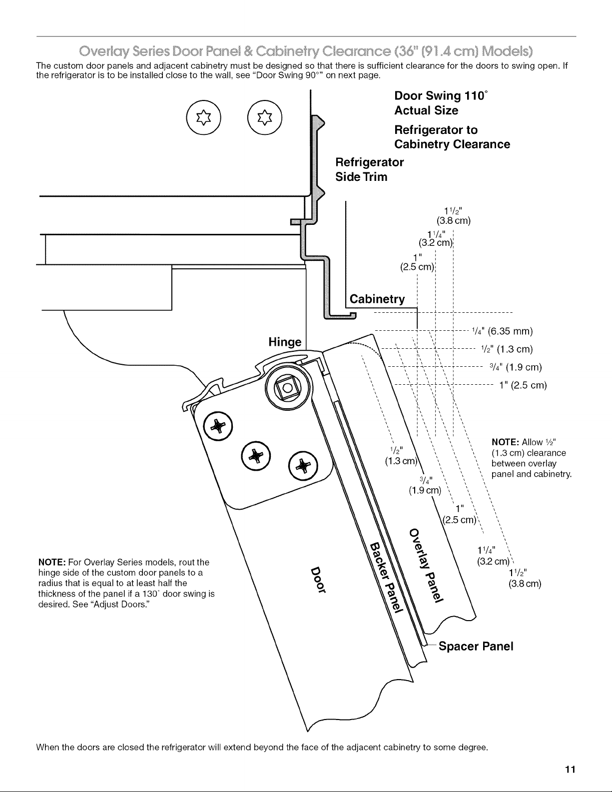
The custom door panels and adjacent cabinetry must be designed so that there is sufficient clearance for the doors to swing open. If
the refrigerator is to be installed close to the wall, see "Door Swing 90 °,' on next page.
Door Swing 110 °
Actual Size
Refrigerator to
Cabinetry Clearance
Refrigerator
Side Trim
I
Hinge
®
NOTE: For Overlay Series models, rout the
hinge side of the custom door panels to a
radius that is equal to at least half the
thickness of the panel if a 130° door swing is
desired. See "Adjust Doors."
era)\,
\
11/4"
(3.2 cm)
1/2"
(3.8 cm)
Panel
When the doors are closed the refrigerator will extend beyond the face of the adjacent cabinetry to some degree.
11
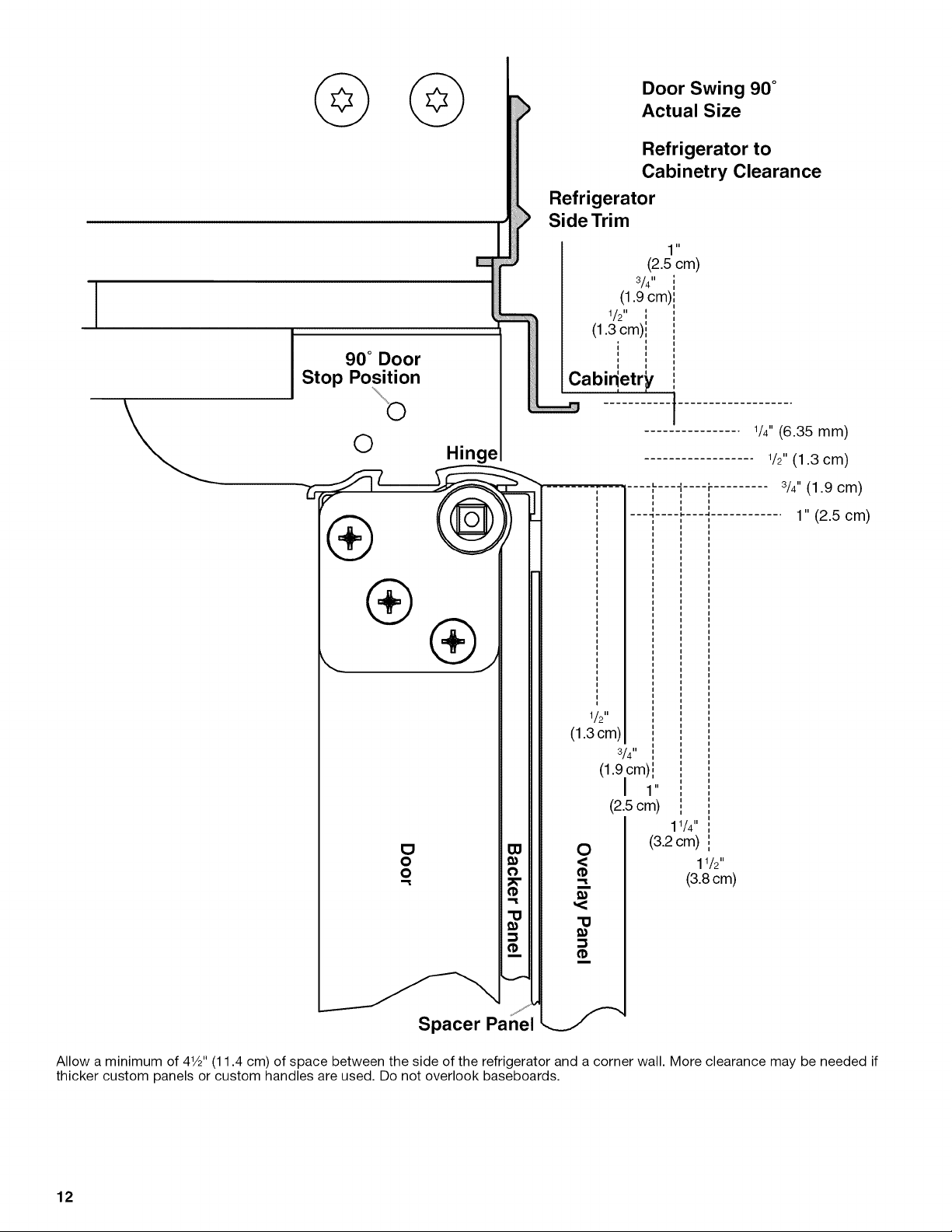
I
90 ° Door
Stop Position
O Hinge
Spacer Panel
Door Swing 90 °
Actual Size
Refrigerator to
Cabinetry Clearance
Refrigerator
Side Trim
11
(2.5 cm)
3/4"
(1.9 cm)
1/ . i
/2 ,,
(1.3 cm)',
',
i i
,, ,,
Cabidetr_
1/2"
(1.3cm)
3/4"
1/4"(6.35 mm)
1/2"(1.3 cm)
3/4"(1.9 cm)
1" (2.5 cm)
0
<
m
(1.9cm)!
I 1"
(2.5ore)
11/4"
(3.2 cm)
11/2"
(3.8ore)
Allow a minimum of 41/2"(11.4 cm) of space between the side of the refrigerator and a corner wall. More clearance may be needed if
thicker custom panels or custom handles are used. Do not overlook baseboards.
12
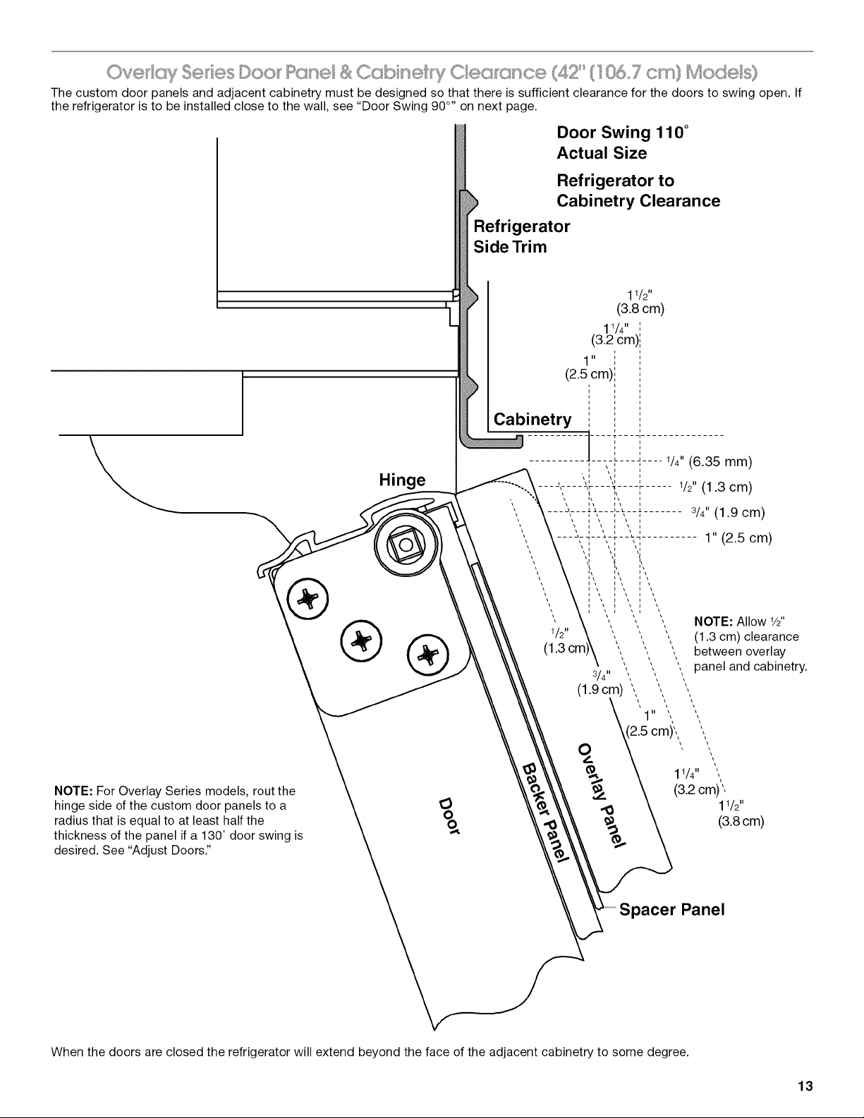
The custom door panels and adjacent cabinetry must be designed so that there is sufficient clearance for the doors to swing open. If
the refrigerator is to be installed close to the wall, see "Door Swing 90 °,' on next page.
Door Swing 110 °
Actual Size
,I
[
I
Hinge
Refrigerator to
Cabinetry Clearance
®
NOTE: For Overlay Series models, rout the
hinge side of the custom door panels to a
radius that is equal to at least half the
thickness of the panel if a 130° door swing is
desired. See "Adjust Doors."
Refrigerator
Side Trim
%
11/4"
(3.2 cm)
1" (2.5 cm)
NOTE: Allow W'
(1.3 cm) clearance
between overlay
panel and cabinetry.
1/2"
(3.8cm)
Panel
When the doors are closed the refrigerator will extend beyond the face of the adjacent cabinetry to some degree.
13
,I
[
90 ° Door
Stop Position
O Hinge
®
®
O
O
"=l
Door Swing 90 °
Actual Size
Refrigerator to
Cabinetry Clearance
Refrigerator
Side Trim
11
(2.5 cm)
3/4"
(1.9 cm)
1 II I
/2 ,,
(1.3 cm),,
; '
i
i i
,, ,,
Cabin_etr_
1/4" (6.35 mm)
1/2" (1.3 cm)
......... r......... 3/4" (1.9 cm)
i
___,a I
1/2"
(1.3 cm)
3/4"
(1.90m) i
I 1"
(2.5cm)
O
<
"=l
i
,<
"O
i
1" (2.5 cm)
11/4"
(3.2 cm)
11/2"
(3.8cm)
Allow a minimum of 41/2"(11.4 cm) of space between the side of the refrigerator and a corner wall. More clearance may be needed if
thicker custom panels or custom handles are used. Do not overlook baseboards.
14
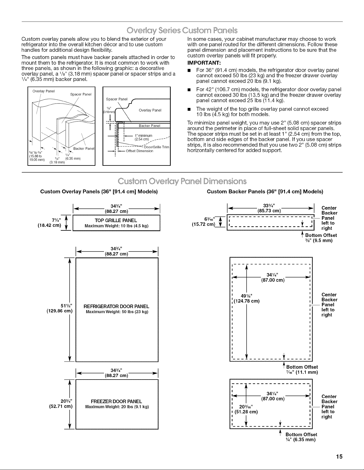
Custom overlay panels allow you to blend the exterior of your
refrigerator into the overall kitchen decor and to use custom
handles for additional design flexibility.
The custom panels must have backer panels attached in order to
mount them to the refrigerator. It is most common to work with
three panels, as shown in the following graphic: a decorative
overlay panel, a 1/8"(3.18 mm) spacer panel or spacer strips and a
I/4"(6.35 mm) backer panel.
Overlay Panel
Spacer Panel
Backer Panel
5/8,,to 3/4,,
(15.88 to W'
19.05 mm) 1/8" (6.35 mm)
(3.18 ram)
I
Spacer Panel
Overlay Panel
Backer Panel
1
1" minimum
[ (2.54 cm). ......
/"
j :DoodGrille Trim
_-_ Offset Dimension
I
J
In some cases, your cabinet manufacturer may choose to work
with one panel routed for the different dimensions. Follow these
panel dimension and placement instructions to be sure that the
custom overlay panels will fit properly.
IMPC RTANT:
• For 36" (91.4 cm) models, the refrigerator door overlay panel
cannot exceed 50 Ibs (23 kg) and the freezer drawer overlay
panel cannot exceed 20 Ibs (9.1 kg).
• For 42" (106.7 cm) models, the refrigerator door overlay panel
cannot exceed 30 Ibs (13.5 kg) and the freezer drawer overlay
panel cannot exceed 25 Ibs (11.4 kg).
• The weight of the top grille overlay panel cannot exceed
10 Ibs (4.5 kg) for both models.
To minimize panel weight, you may use 2" (5.08 cm) spacer strips
around the perimeter in place of full-sheet solid spacer panels.
The spacer strips must be set in at least 1" (2.54 cm) from the top,
bottom and side edges of the backer panel. If you use spacer
strips, it is also recommended that you use two 2" (5.08 cm) strips
horizontally centered for added support.
(.,usom Ovet;ey l: nesso ss
Custom Overlay Panels (36" [91.4 cm] Models) Custom Backer Panels (36" [91.4 cm] Models)
34a/4''(88.27 cm) _ _ 33a/4"(85.73 cm) m Center
Backer
II I 6a/,6"---_-- [ [ i Panel
71/4'' TOPGRILLEPANEL (15.72 cm)___._[, =_ ,= left to
(18.42 cm) Maximum Weight: 10 Ibs (4.5 kg) = right
_'Bottom Offset
%" (9.5 mm)
34a/4"
(88.27 cm)
511/8"
(129.86 cm)
20s/4"
(52.71 cm)
REFRIGERATOR DOOR PANEL
Maximum Weight: 50 Ibs(23 kg)
34a/4''
(88.27 cm)
FREEZER DOOR PANEL
MaximumWeight: 20 Ibs (9.1 kg)
f 3, 1 _:
< (87.00 cm)
491/8''
(124.78 cm)
--I
20sAc ''
(51.28 cm)
341/4''
(87.00 cm)
t
_ Bottom Offset
7A4'(11.1mm)
Center
Backer
.............Panel
leftto
right
Bottom Offset
[
Center
'_ Backer
Panel
' [ left to
' ! right
|
|
1/4"(6.35 mm)
15
Custom Overlay Panels (42" [106.7 cm] Models) Custom Backer Panels (42" [106.7 cm] Models)
407_6 ''
(102.7 cm)
I
7v*'TI ToPGRILU PANEL
(18.4 cm)! j Maximum Weight: 10 Ibs (4.5 kg)
l
511/4''
(130.2 cm)
20" __ __ 20"
(50.8 cm) (50.8 cm)
REFRIGERATOR
DOOR PANEL
MaximumWeight:
30 Ibs (13.5 kg)
REFRIGERATOR
DOOR PANEL
Maximum Weight:
30 Ibs(13.5 kg)
[
511/4''
(130.2 cm)
T
201/4''
(51.4 cm)
!
407/_6 ''
(102.7 cm)
FREEZER DOOR PANEL
Maximum Weight: 25 Ibs (11.4 kg)
39%"
< (100.6 cm) "_
L d ____(15.9 cm)
Side Offset _ Bottom Offset
3/8"(9.5 mm) 1/2"(1.27 cm)
Side
Offset _"
3/16 II
(4.7 mm)
19%" --_
(49.85 cm)
493/16''
(124.93 cm)
Exterior
_"""""""Panel
extends
above
door.
Bottom
Offset
1/211
(1.27 cm)
._ Side
"< Offset
| 3/16 II
I (4.7 mm)
I
Bottom
Offset _
1/211 |
(1.27 em) i
I
.... =_f= =,l
| ........ |
| I
i 40"
I (101.6 cm)
|
197/8"
(50.48 cm)
/
= = = =_=
_t
|
I
I
I
|
Offset all sides
3/16"(4.7 mm)
Spacer Panels (All models)
NOTE: Spacer panels must be at least 1" (2.54 cm) from the top, bottom, and side edges of the backer panel.
3-Piece Grille Overlay Panel Configuration
TopView Side View
I
/
A. Offset dimension
B. ¼" (6.25 mm) Backer panel
C. _" (3.18 mm) Spacer panel
D. ¾" (1.92 cm) Decorative
overlay panel
"_"J'i ..............._ C
.........B
3-Piece Door Overlay Panel Configuration
/
B C D
A. Offset dimension
B. ¼" (6.25 mm) Backer panel
C. _" (3.18 ram) Spacer panel
D. _" (1.92 cm) Decorative overlay panel
1-Piece Overlay Panel Configuration
In some cases, your cabinet manufacturer may choose to work
with one panel routed for the different dimensions. Follow these
panel dimesions and placement instructions to be sure that the
custom overlay panels will fit properly.
16
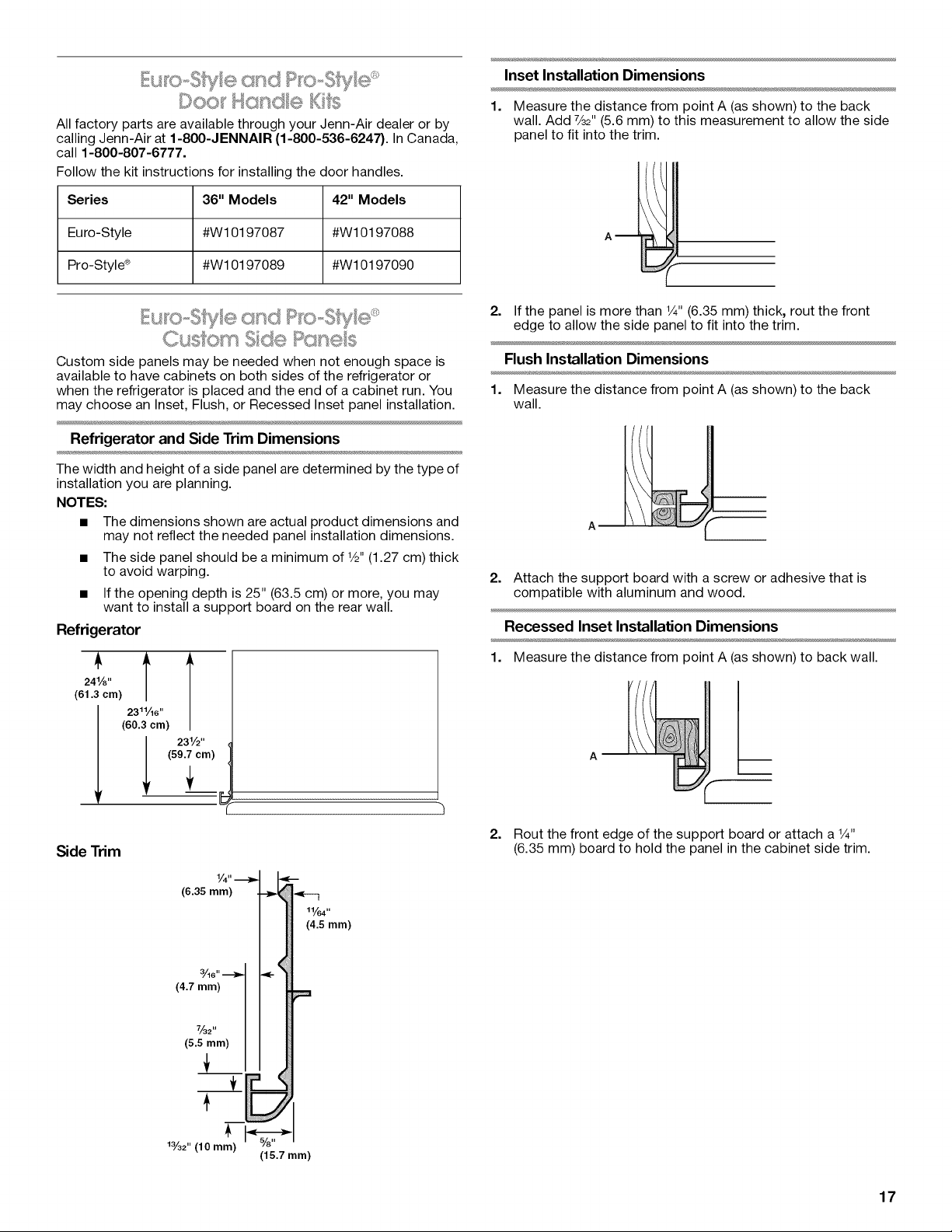
....... #, ,_ _ _-,> _v_i >
All factory parts are available through your Jenn-Air dealer or by
calling Jenn-Air at 1-800-JENNAIR (1-800-536-6247). In Canada,
call 1-800-807-6777.
Follow the kit instructions for installing the door handles.
Series 36" Models 42" Models
Euro-Style #W10197087 #W10197088
Pro-Style ® #W10197089 #W10197090
I:U 0-o I({_ CII'¢;'./;J. y o
Custom side panels may be needed when not enough space is
available to have cabinets on both sides of the refrigerator or
when the refrigerator is placed and the end of a cabinet run. You
may choose an Inset, Flush, or Recessed Inset panel installation.
Refrigerator and Side Trim Dimensions
The width and height of a side panel are determined by the type of
installation you are planning.
NOTES:
• The dimensions shown are actual product dimensions and
may not reflect the needed panel installation dimensions.
• The side panel should be a minimum of %" (1.27 cm) thick
to avoid warping.
• If the opening depth is 25" (63.5 cm) or more, you may
want to install a support board on the rear wall.
Refrigerator
241/8''
(61.3 cm)
(60.3 cm)
231/2,,
(59.7 cm)
Side Trim
Inset Installation Dimensions
1. Measure the distance from point A (as shown) to the back
wall. Add 7/3_"(5.6 mm) to this measurement to allow the side
panel to fit into the trim.
2. If the panel is more than V4"(6.35 mm) thick, rout the front
edge to allow the side panel to fit into the trim.
Flush Installation Dimensions
1. Measure the distance from point A (as shown) to the back
wall.
A m
2.
Attach the support board with a screw or adhesive that is
compatible with aluminum and wood.
Recessed Inset Installation Dimensions
1.
Measure the distance from point A (as shown) to back wall.
2. Rout the front edge of the support board or attach a V4"
(6.35 mm) board to hold the panel in the cabinet side trim.
(6.35 mm)
3/16"
(4.7 mm)
7_2"
(5.5 mm)
t
_3/32"(10 mm)
11/64"
(4.5 mm)
(15.7 mm)
17
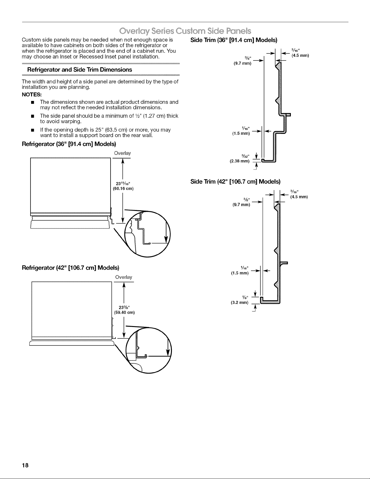
Custom side panels may be needed when not enough space is Side Trim (36" [91.4 cm] Models)
available to have cabinets on both sides of the refrigerator or
when the refrigerator is placed and the end of a cabinet run. You
may choose an Inset or Recessed Inset panel installation.
Refrigerator and Side Trim Dimensions
3/8"
(9.7 mm)
The width and height of a side panel are determined by the type of
installation you are planning.
NOTES:
• The dimensions shown are actual product dimensions and
may not reflect the needed installation dimensions.
The side panel should be a minimum of W' (1.27 cm) thick
to avoid warping.
If the opening depth is 25" (63.5 cm) or more, you may
want to install a support board on the rear wall.
1/16"
(1.5 mm)
Refrigerator (36" [91.4 cm] Models)
Overlay
T
2311/16 ''
(60.16 cm)
Side Trim (42" [106.7 cm] Models)
3/8"
(9.7 mm)
Refrigerator (42" [106.7 cm] Models)
Overlay
233/8''
(59.40 cm)
3
(1.5 mm)
1/8"
(3.2 mm)
3_6"
(4.5 mm)
18
InsetInstallationDimensions
36" [91.4 cm] Models
1. Measure the distance from point A (asshown) to the back
wall. Add 1/32"(0.8 mm) to this measurement to allow the side
panel to fit into the trim.
(-
2. If the panel is more than 3/8"(9.5 mm) thick, rout the front edge
to allow the side panel to fit into the trim
42" [106.7 cm] Models
1. Measure the distance from point A (asshown) to the back
wall. Add 1/32"(0.8 mm) to this measurement to allow the side
panel to fit into the trim.
2. If the panel is more than 3/8"(9.5 mm) thick, rout the front edge
to allow the side panel to fit into the trim.
Recessed Inset Installation Dimensions
36" [91.4 cm] Models
1. Measure the distance from point A (asshown) to back wall.
A
2. Rout the front edge of the support board or attach a 3/8"
(9.5 mm) board to hold the panel in the cabinet side trim.
42" [106.7 cm] Models
1. Measure the distance from point A (as shown) to back wall.
2=
A m
Rout the front edge of the support board or attach a 3/8"
(9.5 mm) board to hold the panel in the cabinet side trim.
INSTALLATIONINSTRUCTIONS
ge ot
Tip Over Hazard
Refrigerator is top heavy and tips easily when not
completely installed.
Keep doors taped closed until refrigerator is
completely installed.
Use two or more people to move and install
refrigerator.
Failure to do so can result in death or serious injury.
IM PORTANI"."
• Do not remove the film until the refrigerator is in its operating
position.
• All four leveling legs must contact the floor to support and
stabilize the full weight of the refrigerator.
• Keep the cardboard shipping piece or plywood under the
refrigerator until it is installed in the operating position.
1=
Remove and save the literature package bag taped to the side
of the refrigerator and the parts bag behind the grille. Remove
the four brackets (two on each side) that attach the shipping
base to the refrigerator bottom.
NOTE: Do not remove tape and door bracing until the
refrigerator is in its final location.
2=
If necessary, reduce the tipping radius. See "Tipping Radius"
for ceiling height requirements or "Reduce Tipping Radius" for
step-by-step instructions. If you do not need to reduce the
tipping radius, proceed to "Move the Refrigerator into House."
; ec (,ce ?ppng F{!<csds
Before bringing the refrigerator into the home, be sure there is
adequate ceiling height to stand the refrigerator upright. See
"Tipping Radius" in the "Installation Requirements" section for
more information.
If you do not have adequate ceiling height to stand the refrigerator
upright, the tipping radius can be reduced by removing the top
grille and side trims (see the following chart).
Model Reduced Tipping Radius
36 88" (223.5 cm)
42 881/2"(224.8 cm)
1. Grasp both ends of the top grille.
19
2. Push the top grille straight up; then pull straight out. Lay the 42" (106.7 cm) Models
grille on a soft surface.
3.
B A B
A. Top grille
B. Cabinet side trim
Remove the six screws attaching each cabinet side trim to the
refrigerator and remove the side trims.
Tip Over Hazard
Refrigerator is top heavy and tips easily when not
completely installed.
Keep doors taped closed until refrigerator is
completely installed.
Use two or more people to move and install
refrigerator.
Failure to do so can result in death or serious injury.
1=
Place an appliance dolly under the left side of the refrigerator
as shown. Be sure to protect the side trims and handles. Place
the corner posts from the packing materials over the trims and
handles as appropriate. Slowly tighten the strap.
NOTE: Pass the dolly strap under the handles.
36" (91.4 cm) Models
2. Place pieces of the shipping carton on the floor when rolling
the dolly and refrigerator into the house. Move the refrigerator
close to the built-in opening.
3. Place top of cardboard carton or plywood under refrigerator.
4. Stand the refrigerator up. First, place the left bottom edge of
the refrigerator on the floor, stand the refrigerator upright and
then lower the right-hand side of the refrigerator to the floor.
Do not remove film or cover.5=
6.
Reassemble the trim and top grille after the dolly has been
removed from the refrigerator.
£sslctl A s,- Boc cs
.......... b
IMPO R'rAN1":
To avoid tipping during use, the solid soffit must be within 1"
(2.5 cm) maximum above the refrigerator. If the solid soffit is
higher than 1" (2.5 cm) or one is not available, then the
refrigerator must be braced.
• It is recommended that board(s) be installed before the
refrigerator is installed.
• Board(s) must be long enough to fully cover the width of the
compressor cover.
• Locate the board(s) so the bottom surface(s) of the board(s)
is(are) 84" (213 cm) from the floor.
During installation, raise the refrigerator up so there is 1/4"
(6.35 mm) maximum between the top of the refrigerator and
the bottom of the anti-tip board(s). Do not crush the
compressor cover when raising the rear leveling legs.
To Install Anti-tip Boards
1. Mark the stud locations on rear wall 80" to 90" (203 cm to
229 cm) above floor.
2. Securely attach one or two 2" x 4" x 32" (5 cm x 10 cm x
81 cm) boards to wall studs behind refrigerator. Use six
#8 x 3" (7.6 cm) (or longer) wood screws. The wood screws
must be screwed into the studs at least 11/2"(3.8 cm). The
board(s) must overlap the compressor cover.
20
A
...... o o o
2" (5 cm)
B
C
e
D
A. Center board ¼" (6.35 mm) max. above refrigerator
B. Two 2" x 4" x 32" (5 cm x 10 cm x 81 cm) boards
C. Attach to studs with six #8 x 3" (7.6 cm) screws
D. Compressor cover
.... ..... ...._ e W_''__< _ ' "_ _'
Read all directions before you begin.
IMPORTANT: If you turn the refrigerator on before the water line is
connected, turn the ice maker OFE
Style I - Shutoff Valve Connection
NOTE: If your water line connection does not look like Style 1, see
"Style 2 - Copper Line Connection."
1. Unplug refrigerator or disconnect power supply.
IMPORTANT: Before attaching the tubing to shutoff valve, flush
the main water supply line to remove particles and air in the water
line. Allow enough flow so that water becomes clear. Flushing the
water line may help avoid filters and/or water valves from
becoming clogged.
2. Remove the shipping tape from the gray, coiled water tubing
on the rear of the refrigerator.
3. Remove the short, black plastic tube from the end of the water
line inlet. This tube protects the fitting during shipping only.
4. Thread the provided nut onto the shutoff valve as shown.
................ C
A.Bulb
B.Nut
C. Water tubing
5. Turn shutoff valve ON.
6. Check for leaks. Tighten any nuts or connections (including
connections at the valve) that leak.
7. Plug in the refrigerator or reconnect power.
8. Flush the water system. See "Water System Preparation."
NOTE: Allow 24 hours to produce the first batch of ice. Discard
the first three batches of ice produced. Allow 3 days to completely
fill ice container.
Style 2 - Copper Line Connection
Connecting to Water Line
NOTE: If existing water line meets the "Water System
Requirements," see "Connecting to Refrigerator."
1. Unplug refrigerator or disconnect power.
2. Turn OFF main water supply. Turn ON nearest faucet long
enough to clear line of water.
3. Locate a 1/2"to 1V4"(1.25 cm to 3.18 cm) vertical cold water
pipe near the refrigerator.
IM PORTANT:
• Make sure it is a cold water pipe.
• Horizontal pipe will work, but drill on the top side of the
pipe, not the bottom. This will help keep water away from
the drill and normal sediment from collecting in the valve.
4. Determine the length of copper tubing you need. Measure
from the connection on the lower left rear of refrigerator to the
water pipe. Add 7 ft (2.1 m) to allow for cleaning. Use V4"
(6.35 mm) O.D. (outside diameter) copper tubing. Be sure both
ends of copper tubing are cut square.
5. Using a cordless drill, drill a V4"(6.35 mm) hole in the cold
water pipe you have selected.
A. Cold water pipe
B. Pipe clamp
C. Copper tubing
D. Compression nut
E. Compression sleeve
F. Shutoff valve
G. Packing nut
6. Fasten the shutoff valve to the cold water pipe with the pipe
clamp. Be sure the outlet end is solidly in the V4"(6.35 mm)
drilled hole in the water pipe and that the washer is under the
pipe clamp. Tighten the packing nut. Tighten the pipe clamp
screws slowly and evenly so washer makes a watertight seal.
Do not overtighten, or you may crush the copper tubing.
7. Slip the compression sleeve and compression nut on the
copper tubing as shown. Insert the end of the tubing into the
outlet end squarely as far as it will go. Screw compression nut
onto outlet end with adjustable wrench. Do not overtighten the
clamp or the sleeve. This will crush the copper tubing.
IMPORTANT: Before attaching the tubing to shutoff valve, flush
the main water supply line to remove particles and air in the water
line. Allow enough flow so that water becomes clear. Flushing the
water line may help avoid filters and/or water valves from
becoming clogged.
8. Turn off the shutoff valve on the water pipe. Coil the copper
tubing.
9. Check for leaks around the saddle valve.
21
Connecting to Refrigerator
1. Unplug the refrigerator or disconnect power.
2. Remove the shipping tape from the gray, coiled water tubing
on the rear of the refrigerator.
3. Remove the short, black plastic tube from the end of the water
line inlet. This tube protects the fitting during shipping only.
4. Measure the distance from the shutoff valve to the opening in
which the refrigerator will be located. Tubing must be
extended from the shutoff valve into the refrigerator opening
following specific guidelines. See "Water Supply
Requirements."
5. A 1/4"x 1/4"(6.35 mm to 6.35 mm) coupling is needed in order
to connect the water tubing to an existing household water
line. Thread the provided nut onto the coupling on the end of
the copper tubing.
A B
A. Water tubing
B. Nut
C. Bulb
D. Coupfing (purchased)
6. Turn shutoff valve ON.
C D E F G
E. Ferrule (purchased)
F Nut (purchased)
G. Household water line (as
connected in previous section)
7. Check for leaks. Tighten any nuts or connections (including
connections at the valve) that leak.
8. Plug in the refrigerator or reconnect power.
9. Flush the water system. See "Water System Preparation."
NOTE: Allow 24 hours to produce the first batch of ice. Discard
the first three batches of ice produced. Allow 3 days to completely
fill ice container.
Electrical Shock Hazard
Plug into a grounded 3 prong outlet.
Do not remove ground prong.
Do not use an adapter.
Do not use an extension cord.
Failure to folow these instructions can result in death,
fire, or electrical shock.
1. Set control switch at top of cabinet to the OFF position.
2. Plug into a grounded 3 prong outlet.
Tip Over Hazard
Refrigerator is top heavy and tips easily when not
completely installed.
Keep doors taped closed until refrigerator is
completely installed.
Use two or more people to move and install
refrigerator.
Failure to do so can result in death or serious injury.
IMPORTANT: To avoid floor damage, make sure levelers are
raised (not touching floor) and refrigerator is on rollers before
moving.
1. Place top of cardboard carton or plywood under refrigerator.
Remove dolly.
Do not remove film or cover.2.
3.
Move the refrigerator straight back and evenly into the
opening. Be sure that the refrigerator side trims are not
interfering with the door opening. Also, be sure that the water
tubing is not kinked and the power supply cord is on top of the
refrigerator.
A ; ef ge ot
Tip Over Hazard
Refrigerator is top heavy and tips easily when not
completely installed.
Keep doors taped closed until refrigerator is
completely installed.
Use two or more people to move and install
refrigerator.
Failure to do so can result in death or serious injury.
IMPORTANT: All four leveling legs must contact the floor to
support and stabilize the full weight of refrigerator. Rollers are for
moving refrigerator and not for permanent support.
22
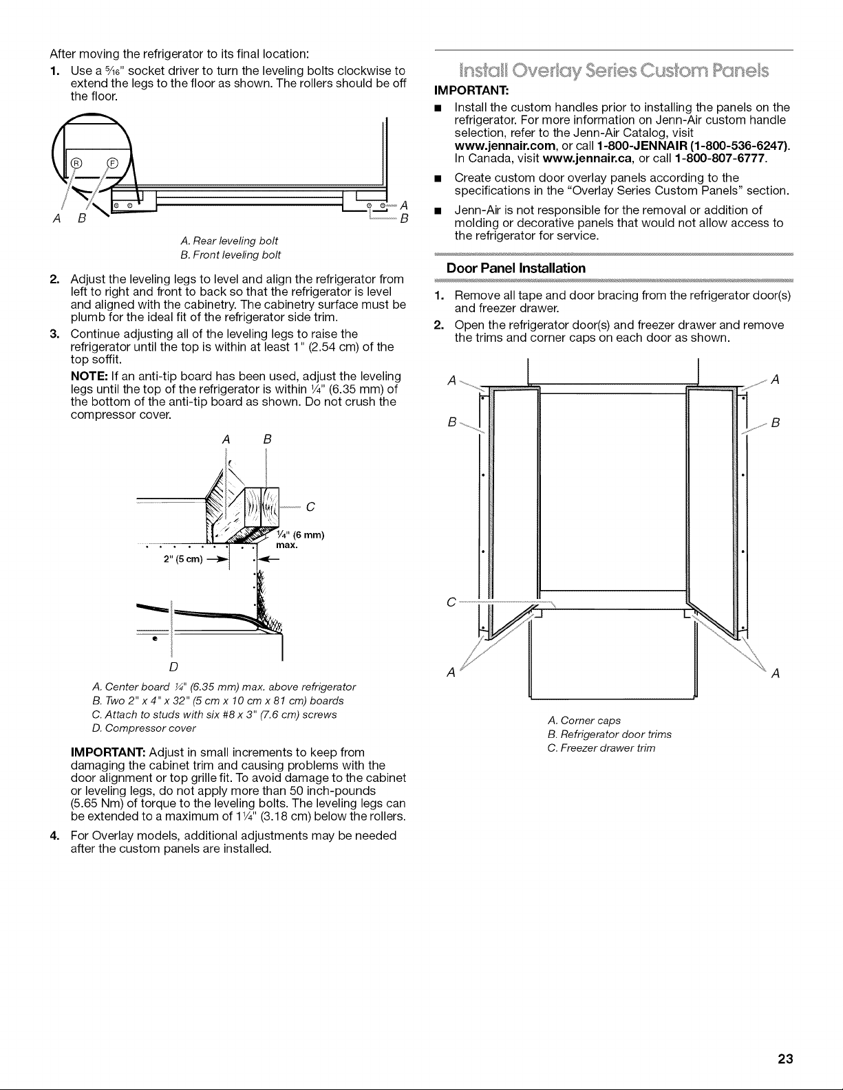
After moving the refrigerator to its final location:
1. Use a 5Ae"socket driver to turn the leveling bolts clockwise to
extend the legs to the floor as shown. The rollers should be off
the floor.
2,
3,
A. Rear leveling bolt
B. Front leveling bolt
Adjust the leveling legs to level and align the refrigerator from
left to right and front to back so that the refrigerator is level
and aligned with the cabinetry. The cabinetry surface must be
plumb for the ideal fit of the refrigerator side trim.
Continue adjusting all of the leveling legs to raise the
refrigerator until the top is within at least 1" (2.54 cm) of the
top soffit.
NOTE: If an anti-tip board has been used, adjust the leveling
legs until the top of the refrigerator is within 1/4"(6.35 mm) of
the bottom of the anti-tip board as shown. Do not crush the
compressor cover.
A B
2" (5 cm)
C
/4" (6 mm)
max.
4,
D
A. Center board _" (6.35 mm) max. above refrigerator
B. Two 2" x 4" x 32" (5 cm x 10 cm x 81 cm) boards
C. Attach to studs with six #8 x 3" (7.6 cm) screws
D. Compressor cover
IMPORTANT: Adjust in small increments to keep from
damaging the cabinet trim and causing problems with the
door alignment or top grille fit. To avoid damage to the cabinet
or leveling legs, do not apply more than 50 inch-pounds
(5.65 Nm) of torque to the leveling bolts. The leveling legs can
be extended to a maximum of 11/4"(3.18 cm) below the rollers.
For Overlay models, additional adjustments may be needed
after the custom panels are installed.
IM PORTANT:
Install the custom handles prior to installing the panels on the
refrigerator. For more information on Jenn-Air custom handle
selection, refer to the Jenn-Air Catalog, visit
www.jennair.com, or call 1-800-JENNAIR (1-800-536-6247).
In Canada, visit www.jennair.ca, or call 1-800-807-6777.
• Create custom door overlay panels according to the
specifications in the "Overlay Series Custom Panels" section.
• Jenn-Air is not responsible for the removal or addition of
molding or decorative panels that would not allow access to
the refrigerator for service.
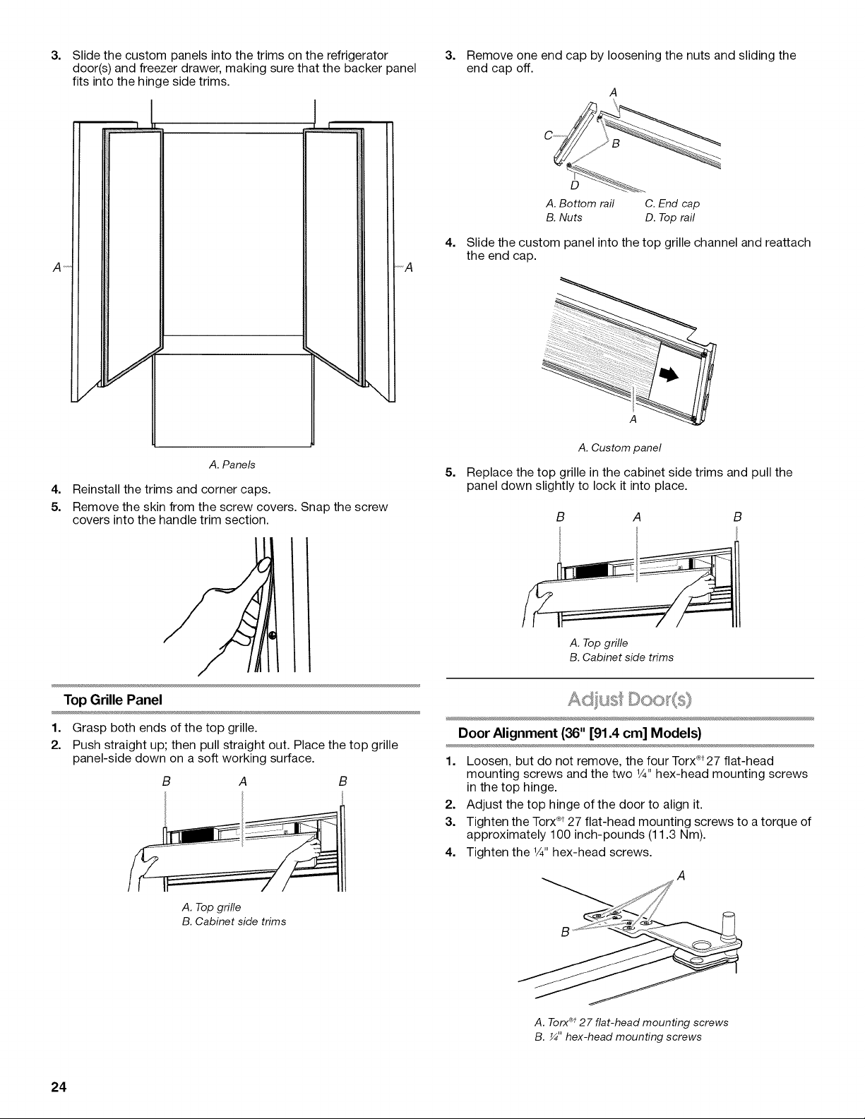
Door Panel Installation
1. Remove all tape and door bracing from the refrigerator door(s)
and freezer drawer.
2. Open the refrigerator door(s) and freezer drawer and remove
the trims and corner caps on each door as shown.
! , A
S .............
B
A iiii_A
A. Corner caps
B. Refrigerator door trims
C. Freezer drawer trim
23
3=
A _
4=
5.
Slide the custom panels into the trims on the refrigerator
door(s) and freezer drawer, making sure that the backer panel
fits into the hinge side trims.
............................L ..........
A. Panels
Reinstall the trims and corner caps.
Remove the skin from the screw covers. Snap the screw
covers into the handle trim section.
3. Remove one end cap by loosening the nuts and sliding the
end cap off.
A
C ...........
A.Bottom rail C.End cap
B.Nuts D. Toprail
4. Slide the custom panel into the top grille channel and reattach
the end cap.
5=
A. Custom panel
Replace the top grille in the cabinet side trims and pull the
panel down slightly to lock it into place.
B A B
A. Top grille
B. Cabinet side trims
Top Grille Panel
1. Grasp both ends of the top grille.
2. Push straight up; then pull straight out. Place the top grille
panel-side down on a soft working surface.
B A B
Door Alignment (36" [91.4 cm] Models)
1. Loosen, but do not remove, the four Torx®t27 flat-head
mounting screws and the two 1/4"hex-head mounting screws
in the top hinge.
2. Adjust the top hinge of the door to align it.
3. Tighten the Torx®t27 flat-head mounting screws to a torque of
approximately 100 inch-pounds (11.3 Nm).
4. Tighten the 1/4"hex-head screws.
A. Top grille
B. Cabinet side trims
A. Torx®t27 flat-head mounting screws
B. _" hex-head mounting screws
24
 Loading...