


Jenn-Air JB36NXFXLE, JB36NXFXRE, W10663562, JBBFR36NHL, JBBFL36NHL Owner's Manual
...
iNstaLl
BOTTOM MOUNT BUILT-IN REFRIGERATOR
RÉFRIGÉRATEUR ENCASTRÉ AVEC CONGÉLATEUR EN BAS
For questions about features, operation/performance, parts, accessories, or service, call:
1-800-JENNAIR (1-800-536-6247) or visit our website at www.jennair.com.
In Canada, call: 1-800-JENNAIR (1-800-536-6247), or visit our website at www.jennair.ca.
Pour des questions à propos des caractéristiques, du fonctionnement/rendement, des pièces, accessoires ou service, composer le : 1 800 JENNAIR (1 800 536-6247) ou visiter notre site Web au www.jennair.com.
Au Canada, composer le : 1 800 JENNAIR (1 800 536-6247) ou visiter notre site Web au www.jennair.ca.
W10735232B
TABLE OF CONTENTS |
|
INTRODUCTION |
|
Refrigerator Safety....................................................................................... |
3 |
VARIANTS AND ACCESSORIES |
|
36" Single-Door Models ........................................................................... |
4 |
36" and 42" French Door Models ...................................................... |
5 |
INSTALLATION REQUIREMENTS |
|
Tools and Parts............................................................................................... |
6 |
Location Requirements............................................................................ |
7 |
Electrical Requirements.......................................................................... |
8 |
Water Supply Requirements................................................................ |
9 |
Product Dimensions................................................................................... |
9 |
Door Swing Dimensions.......................................................................... |
11 |
PERMISSIBLE Installation Options................................................... |
12 |
Stainless Steel Panel Kit |
|
Installation Requirements...................................................................... |
12 |
Custom Wood Panel Dimensions and Installation |
|
Requirements................................................................................................. |
12 |
INSTALLATION INSTRUCTIONS |
|
Unpack the Refrigerator.......................................................................... |
13 |
Move the Refrigerator into House.................................................... |
13 |
Install Anti-Tip Boards............................................................................... |
14 |
Connect the Water Supply..................................................................... |
14 |
Plug in Refrigerator.................................................................................... |
16 |
Install Side Trims........................................................................................... |
16 |
Move Refrigerator to |
|
Final Location.................................................................................................. |
17 |
Level and Align Refrigerator................................................................. |
17 |
Install Panels.................................................................................................... |
18 |
Install Base Grille........................................................................................... |
18 |
Complete Installation................................................................................ |
19 |
TABLE DES MATIÈRES |
|
INTRODUCTION |
|
Sécurité du réfrigérateur......................................................................... |
20 |
VARIANTES ET ACCESSOIRES |
|
Modèle avec porte simple de 36 po ................................................ |
21 |
Modèles avec porte à double battant de 36 po et 42 po .22 |
|
EXIGENCES D’INSTALLATION |
|
Outils et pièces............................................................................................... |
23 |
Exigences d’emplacement.................................................................... |
24 |
Spécifications électriques...................................................................... |
25 |
Spécifications de l’alimentation en eau....................................... |
26 |
Dimensions du produit............................................................................ |
26 |
Dimensions pour l’ouverture des portes...................................... |
28 |
OPTIONS D’INSTALLATIONS PERMISE.......................................... |
29 |
Exigences d’installation de l’ensemble de panneaux en |
|
acier inoxydable............................................................................................. |
29 |
Exigences d’installation et dimensions des panneaux de |
|
bois personnalisés........................................................................................ |
29 |
INSTRUCTIONS D’INSTALLATION |
|
Déballage du réfrigérateur.................................................................... |
30 |
Déplacement du réfrigérateur dans le domicile.................... |
30 |
Installation de planches antibasculement................................. |
31 |
Raccordement à la canalisation d’eau........................................... |
31 |
Brancher le réfrigérateur........................................................................ |
33 |
Installation des garnitures latérales................................................. |
34 |
Déplacement du réfrigérateur à son emplacement |
|
définitif................................................................................................................. |
34 |
Réglage de l’aplomb et alignement du réfrigérateur........ |
35 |
Installation des panneaux...................................................................... |
35 |
Installation de la grille de la base...................................................... |
36 |
Terminer l’installation................................................................................ |
36 |
2
INTRODUCTION
REFRIGERATOR SAFETY
Your safety and the safety of others are very important.
many important safety messages in this manual and on your appliance. Always read and obey all safety
safety alert symbol.
alerts you to potential hazards that can kill or hurt you and others.
messages will follow the safety alert symbol and either the word “DANGER” or “WARNING.” mean:
 DANGER
  WARNING
You can be killed or seriously injured if you don't immediately follow instructions.
You can be killed or seriously injured if you don't follow instructions.
All safety messages will tell you what the potential hazard is, tell you how to reduce the chance of injury, and tell you what can happen if the instructions are not followed.
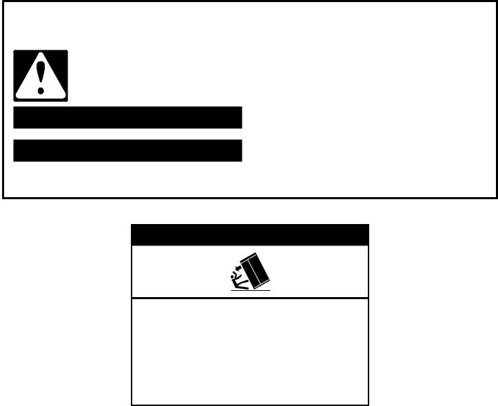
 WARNING
Tip Over Hazard
Refrigerator is top heavy and tips easily when not completely installed.
Keep doors taped closed until refrigerator is completely installed.
Use two or more people to move and install refrigerator.
Failure to do so can result in death or serious injury.
3
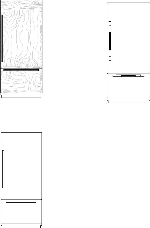
VARIANTS AND ACCESSORIES
36" SINGLE-DOOR MODELS
Custom-Made Panel Design
Features custom-made panels and custom hardware provided by the cabinetmaker for a seamless appearance designed to blend with existing kitchen cabinetry.
Base Model Numbers: JB36NXFXLE, JB36NXFXRE
ARMOIRE KIT NUMBER: W10663562
NOIR™ Stainless Design
Features stainless steel wrapped doors and new NOIR™ handles.
Base Model Numbers: JB36NXFXLE, JB36NXFXRE Panel Kit Model Number: JBBFR36NHM, JBBFL36NHM
RISE™ Stainless Design
Features stainless steel wrapped doors and new RISE™ handles.
Base Model Numbers: JB36NXFXLE, JB36NXFXRE Panel Kit Model Number: JBBFR36NHL, JBBFL36NHL
ACCESSORIES
All factory parts are available through JennAir dealer or by calling JennAir® at 1-800-JENNAIR (1-800-536-6247). In Canada, call 1-800-536-6247.
DOOR HANDLE KITS
For custom wood overlay panels only, handle kits can be ordered. Follow the kit instructions for installation.
Handle Kits contain 2 handles per Kit.
IMPORTANT: These handle kits are not intended for use with stainless steel door panel kits.
RISE™ Stainless Steel—BM—W11231245
NOIR™ Stainless Steel—BM—W11194767
ARMOIRE-STYLE DOOR PANEL KIT
Refer to the installation instructions that come with the Armoire kit, for custom wood overlay panel dimensions and installation details.
36" Model — W10663562
4

36" AND 42" FRENCH DOOR MODELS
Custom-Made Panel Design
Features custom-made panels and custom hardware provided by the cabinetmaker for a seamless appearance designed to blend with existing kitchen cabinetry.
Base Model Numbers: JF42NXFXDE, JF36NXFXDE ARMOIRE KIT NUMBER: W10663562, W10663564
NOIR™ Stainless Design
Features stainless steel wrapped doors and new NOIR™ handles.
Base Model Numbers: JF42NXFXDE, JF36NXFXDE Panel Kit Model Number: JBFFS42NHM, JBFFS36NHM
RISE™ Stainless Design
Features stainless steel wrapped doors and new RISE™ handles.
Base Model Numbers: JF42NXFXDE, JF36NXFXDE Panel Kit Model Number: JBFFS42NHL, JBFFS36NHL
ACCESSORIES
All factory parts are available through JennAir dealer or by calling JennAir® at 1-800-JENNAIR (1-800-536-6247). In Canada, call 1-800-536-6247.
DOOR HANDLE KITS
For custom wood overlay panels only, handle kits can be ordered. Follow the kit instructions for installation.
Handle Kits contain 3 handles per Kit.
IMPORTANT: These handle kits are not intended for use with stainless steel door panel kits.
RISE™ Stainless Steel—36" FDBM—W11231247 NOIR™ Stainless Steel—36" FDBM—W11194768 RISE™ Stainless Steel—42" FDBM—W11296021 NOIR™ Stainless Steel— 42" FDBM—W11194769
ARMOIRE-STYLE DOOR PANEL KIT
Refer to the installation instructions that come with the Armoire kit, for custom wood overlay panel dimensions and installation details.
36" Model — W10663562
42" Model — W10663564
5
INSTALLATION REQUIREMENTS
TOOLS AND PARTS
IMPORTANT:
Installer: Leave Installation Instructions with the homeowner.
Homeowner: Keep Installation Instructions for future reference. Save these Installation Instructions for the local electrical inspector’s use.
TOOLS NEEDED:
Gather the required tools and parts before starting installation.
Read and follow the instructions provided with any tools listed here.
Cordless drill
Drill bits
Adjustable wrenches (2)
Phillips screwdriver
Small level
3/32" hex key (panel kits only)
11/32" nut driver
PARTS NEEDED:
3/8" and 1/2" open-end wrenches
5/32" and 3/16" hex key
1/4" and 5/16" socket drivers
Tape measure
Utility knife
Tape (painters)
Appliance dolly
#8 x 3" (7.6 cm) wood screws (longer screws may be needed) (6)
2" x 4" x 32" (5 cm x 10 cm x 81 cm) wood boards (2)
Custom wood overlay panels—consult a qualified cabinetmaker or carpenter to make the custom wood panels.
See “Custom Wood Overlay Panels” for more information.
OR
Panel kit—See “Variants and Accessories” for panel kit information.
Flexible, codes-approved water supply tubing, a ferrule, a union and a 1/4" (6.35 mm) compression fitting.
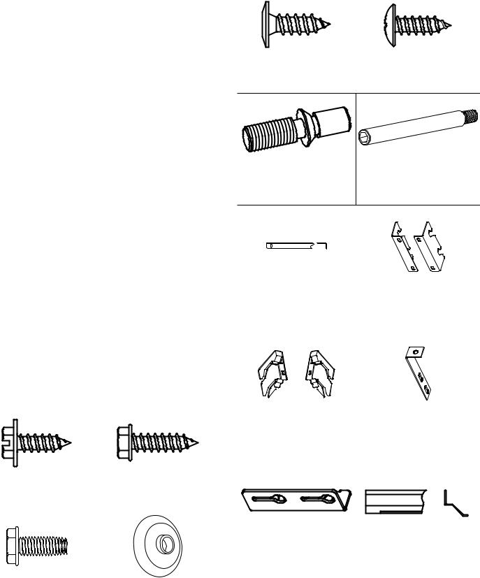
Slotted Hex-head Screw |
Hex-head Pointed Screw |
W10141645 (21) |
W10141189 (8) |
|
|
Hex-head Blunt Screw |
Shoulder Washer (use with |
W10142233 (4) |
hex-head pointed screw) |
|
W10471946 (4) |
Phillips-head Flat Screw |
Round-head Screw |
8281252 (28) |
1163283 (24) |
|
|
Door Adjustment Pin |
Door Stop Pin |
(preinstalled) |
W10234202 (2) |
W10234194 (2) |
|
Drawer Panel Bracket |
Standard Integrated Grille |
W10606815 (2) |
Bracket |
|
W10182743—Left (1) |
|
W10182741—Right (1) |
|
|
Fully Integrated Grille |
Filler Board “L” Bracket |
Bracket |
W10234199 (2) |
W10260890—Left (1) |
|
W10260891—Right (1) |
|
|
|
Panel Top Bracket |
Top Grille Lower Trim |
W10667450 (2) |
W10634858—36" BM (1) |
|
W10606812—42" BM, SxS (1) |
|
|
6

RC Hinge Cover Trim |
FC Hinge Cover Trim |
W10648975—36" BM |
W10611107—36" BM (Left) |
(Right) |
W10582015—36" FDBM |
W10564251—36" FDBM |
(Left) |
(Right) |
W10606808—42" FDBM |
W10606804—42" FDBM |
(Left) |
(Right) |
|
Panel Templates |
Handle Side Door Trim |
W10222281—SxS |
W10611106—BM (Left) |
W10488115—36" BM |
W10648977—BM (Right |
W10704869—36" FDBM |
W10606802—FDBM (Right |
W10488118—42" FDBM |
W10606806—FDBM (Left) |
W10489178—Grille |
|
|
|
|
|
|
|
|
|
|
|
|
|
|
|
|
|
|
|
|
|
|
|
|
|
|
|
|
|
|
|
|
|
|
|
|
|
|
|
|
|
|
|
|
|
|
|
|
|
|
|
|
|
|
|
|
|
|
|
|
|
Installation Block |
Grille—Bottom / Skirt— |
|||||||||||||
W10234156 |
Grille |
|||||||||||||
|
|
|
|
|
|
|
|
|
|
|
|
|
W10189198 / W10188549— |
|
|
|
|
|
|
|
|
|
|
|
|
|
|
42" BM |
|
|
|
|
|
|
|
|
|
|
|
|
|
|
W10189196 / W10188547— |
|
|
|
|
|
|
|
|
|
|
|
|
|
|
36" BM |
|
|
|
|
|
|
|
|
|
|
|
|
|
|
|
|
LOCATION REQUIREMENTS
 WARNING
Explosion Hazard
Keep flammable materials and vapors, such as gasoline, away from refrigerator.
Failure to do so can result in death, explosion, or fire.
IMPORTANT: This refrigerator is designed for indoor, household use only.
This appliance is intended to be used in household and similar applications such as:
Staff kitchen areas in shops, offices and other working environments.
Farm houses and by clients in hotels, motels and other residential type environments.
Bed and breakfast type environments.
Catering and similar non-retail applications.
NOTE: The refrigerator is intended for use in a location where the temperature ranges from a minimum of 55°F (13°C) to a maximum of 110°F (43°C). The preferred room temperature range for optimum performance, which reduces electricity usage and provides superior cooling, is between 60°F (15°C) and 90°F (32°C). It is recommended that you do not install the refrigerator near a heat source, such as an oven or radiator.
IMPORTANT:
Observe all governing codes and ordinances.
Floor must support the refrigerator weight, more than 600 lbs (272 kg), door panels and contents of the refrigerator. Flooring under refrigerator must be at same level as the room. Face of cabinetry must be plumb.
Location should permit door to open fully. See “Door Swing Dimensions.”
Location must permit top grille removal. See “Opening Dimensions.”
OPENING DIMENSIONS
IMPORTANT:
The width of the opening (Width A), from side to side, must be as specified for your model, for at least
2" (5.08 cm) back from the face of the cabinet.
NOTE: If your opening does not meet this requirement, you will need to make modifications.
A solid soffit or wall cabinet must be installed 84" (213.4 cm) above the floor. If the solid soffit is higher than 84" (213.4 cm) or one is not available, then the refrigerator must be braced.
If anti-tip boards are needed, they must be attached to the rear wall studs so that there is 84" (213.4 cm) from the bottom of the anti-tip board to the floor. See “Install AntiTip Boards” for more information.
NOTES:
A clearance of 1/2" (1.3 cm) must be maintained above the top grille so that the top grille can be removed.
Do not remove the foam gasket from the top of the compressor cover unless removal is necessary to fit the unit under a soffit. Removal of the gasket will cause loss in cooling efficiency.
7
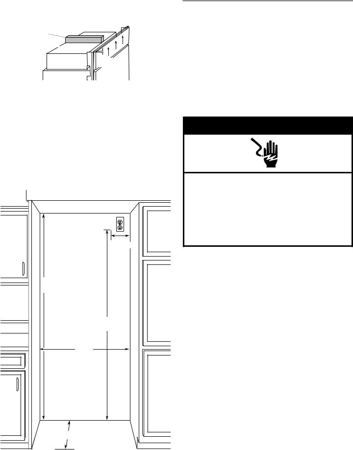
If installing under a solid soffit, after installation raise the leveling legs so that the gasket is pressed snugly against the soffit.
A
B 
1/2" (1.3 cm)
A.Gasket
B.Compressor cover
A grounded 3 prong electrical outlet should be located within a specified number of inches from the right-hand side cabinets or end panel. See the chart following the graphic for the number of inches required for your model. For more information, see “Electrical Requirements.”
The water shutoff should be located in the base cabinet on either side of the refrigerator or some other easily accessible area. If the water shutoff valve is not in the cabinets, the plumbing for the water line can come through the floor. See “Water Supply Requirements” for more information.
B
Dimension
84" (213.4 cm)
to bottom of solid soffit
77"
(196 cm)
A
Width
(see chart following)
C Depth
8
|
WIDTH A |
DIMENSION B |
|
MODEL |
(AS SHOWN |
||
(AS SHOWN ABOVE) |
|||
|
ABOVE) |
||
|
|
||
36 |
36" (91.4 cm) |
4" (10.2 cm) |
|
42 |
42" (106.7 cm) |
7¹⁄ " (19.1 cm) |
|
|
|
|
|
|
|
|
|
INSTALLATION TYPE |
DEPTH C |
||
(AS SHOWN ABOVE) |
|||
|
|
||
Standard Flush |
25" (63.5 cm) minimum |
||
(new installation) |
|
||
Retrofit Installations |
24" (60.9 cm) minimum |
||
|
|
|
|
ELECTRICAL REQUIREMENTS
 WARNING
Electrical Shock Hazard Plug into a grounded 3 prong outlet. Do not remove ground prong.
Do not use an adapter.
Do not use an extension cord.
Failure to follow these instructions can result in death, fire, or electrical shock.
Before you move your refrigerator into its final location, it is important to make sure that you have the proper electrical connection.
RECOMMENDED GROUNDING METHOD
A 115 V, 60 Hz, AC only, 15 or 20 A fused, grounded electrical supply is required. It is recommended that a separate circuit serving only your refrigerator be provided. Use an outlet that cannot be turned off by a switch. Do not use an extension cord.
If the supply cord is damaged, it must be replaced by the manufacturer or its service agent or a similarly qualified person. Do not use a cord that shows cracks or abrasion damage along its length or at either the plug or connector end.
IMPORTANT: If this product is connected to a GFCI (Ground Fault Circuit Interrupter) protected outlet, nuisance tripping of the power supply may occur, resulting in loss of cooling. Food quality and flavor may be affected. If nuisance tripping has occurred, and if the condition of the food appears poor, dispose of it.
NOTE: Before performing any type of installation or cleaning, remove the top grille and turn the master power switch to OFF or disconnect power at the circuit breaker box.
When you are finished, turn ON the master power switch or reconnect power at the circuit breaker box. Then reset the control to the desired setting.

WATER SUPPLY REQUIREMENTS
IMPORTANT:
All installations must meet local plumbing code requirements.
Connect to potable water supply only.
Do not use with water that is microbiologically unsafe or of unknown quality without adequate disinfection before or after the system. Systems certified for cyst reduction may be used on disinfected waters that may contain filterable cysts.
There is not enough clearance to achieve a flush installation if a water shutoff valve is located in the wall behind the refrigerator.
The water shutoff should be located in the base cabinet on either side of the refrigerator or some other easily accessible area. The water supply line, however, must come up through the floor in the gray shaded area shown.
6" (15.2 cm)
6" |
1" |
6" |
|
(2.54 cm) |
|||
(15.2 cm) |
(15.2 cm) |
||
|
A 1/2" (12.7 mm) hole for plumbing should be drilled on the floor at least 6" (15.2 cm) from the rightor lefthand side cabinet and should be no more than
1" (2.54 cm) away from the back wall. See “Connect the Water Supply.”
The water supply connection is made at the front of the refrigerator.
If additional tubing is needed, use copper tubing and check for leaks. Install the copper tubing only in areas where the household temperatures will remain above freezing.
Do not use a piercing-type or 3/16" (4.76 mm) saddle valve which reduces water flow and also clogs more easily.
NOTE: JennAir® refrigerator dealer has a kit available with a 1/4" (6.35 mm) saddle-type shutoff valve, a union, and copper tubing. Before purchasing, make sure that a saddle-type valve complies with your local plumbing codes.
WATER PRESSURE
A cold water supply with water pressure between 30 and 120 psi (207 and 827 kPa) is required to operate the water dispenser and ice maker. If you have questions about your water pressure, call a licensed, qualified plumber.
REVERSE OSMOSIS WATER SUPPLY
IMPORTANT: The pressure of the water supply coming out of a reverse osmosis system going to the water inlet valve of the refrigerator needs to be between
30 and 120 psi (207 and 827 kPa).
If a reverse osmosis water filtration system is connected to your cold water supply, the water pressure to the reverse osmosis system needs to be a minimum of
40 to 60 psi (276 to 414 kPa).
If the water pressure to the reverse osmosis system is less than 40 to 60 psi (276 to 414 kPa):
Check to see whether the sediment filter in the reverse osmosis system is blocked. Replace the filter if necessary.
Allow the storage tank on the reverse osmosis system to refill after heavy usage.
If your refrigerator has a water filter, it may further reduce the water pressure when used in conjunction with a reverse osmosis system. Remove the water filter cartridge.
If you have questions about your water pressure, call a licensed, qualified plumber.
PRODUCT DIMENSIONS
IMPORTANT:
The depth from the front face of the doors to the back of the refrigerator cabinet is 24" (60.96 cm) without panels.
The power cord is 84" (213 cm) long.
The water supply connection is made at the bottom front of the refrigerator.
36" SINGLE-DOOR AND 36" FRENCH DOOR BOTTOM MOUNT
TOP VIEW
24" (61.0 cm)
35³⁄ " (90.8 cm)
9
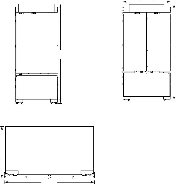
FRONT VIEW
Width dimensions were measured from hinge edge to clip edge.
When leveling legs are fully extended to 1¹⁄ " (3.2 cm) below rollers, add 1¹⁄ " (3.2 cm) to the height dimension.
35³⁄ "  (90.8 cm)

83¹⁄ " (211.1 cm)
FRONT VIEW
Width dimensions were measured from hinge edge to hinge edge.
When leveling legs are fully extended to 1¹⁄ " (3.2 cm) below rollers, add 1¹⁄ " (3.2 cm) to the height dimension.
41³⁄ " (106.1 cm)
83¹⁄ " (211.1 cm)
42" FRENCH DOOR BOTTOM MOUNT
TOP VIEW
24" (61.0 cm)
41³⁄ " (106.1 cm)
10
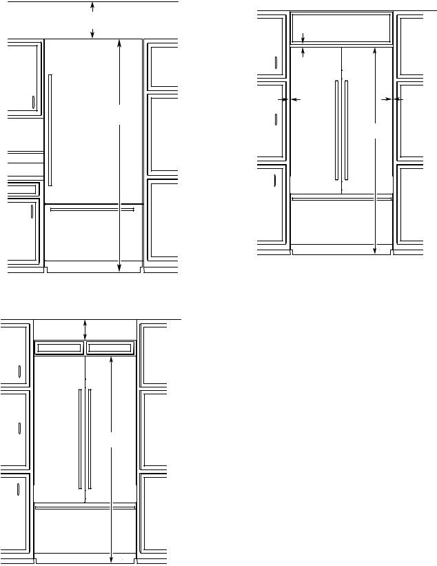
DOOR SWING DIMENSIONS
The location must permit both doors to open to a minimum of 90°.
Allow 4¹⁄ " (11.4 cm) minimum space between the side of the refrigerator and a corner wall.
NOTE: More clearance may be required if you are using custom wood overlay panels, custom handles or extended handles.
36" (91.4 CM) SINGLE-DOOR MODELS
B
A
90º
110º
36" (91.4 CM) AND 42" (106.6 CM) FRENCH DOOR MODELS
A B |
C D |
90˚ |
90˚ |
110˚ |
110˚ |
MODEL |
A |
B |
C |
D |
36 |
58³⁄ " |
56 ⁄ " |
56 ⁄ " |
58³⁄ " |
|
(149.2 cm) |
(143.8 cm) |
(143.8 cm) |
(149.2 cm) |
36 FD |
41" |
39³⁄ " |
39³⁄ " |
41" |
|
(104 cm) |
(101 cm) |
(101 cm) |
(104 cm) |
42 FD |
44" |
42³⁄ " |
42³⁄ " |
44" |
|
(111.8 cm) |
(108.6 cm) |
(108.6 cm) |
(111.8 cm) |
11
PERMISSIBLE INSTALLATION OPTIONS
OPTION 1—OPEN TO CEILING
6" (15.24 cm) min.
84" (213.4 cm)
OPTION 2—FALSE FRONT (CABINET FACE ONLY)
6" (15.24 cm) min.
OPTION 3—CLOSED SOFFIT
1/8" (3.2 mm) gap
1/8" (3.2 mm) gap |
1/8" (3.2 mm) gap |
84" (213.4 cm)
STAINLESS STEEL PANEL KIT INSTALLATION REQUIREMENTS
Refer instructions received with full height door panel kit.
CUSTOM WOOD PANEL DIMENSIONS AND INSTALLATION REQUIREMENTS
Refer instructions received with Armoire kit.
84" (213.4 cm)
12
 Loading...