


 BASS550
Powered Subwoofer
120 Volt & 230 Volt Versions
SERVICE MANUAL
JBL Consumer Products Inc.
80 Crossways Park West
Woodbury, N.Y. 11797
1-800-336-4JBL in the USA
A Harman International Company
Part No.: 1112-JBLBASS550

Powered Subwoofer  BASS550
TABLE OF CONTENTS
Specifications ................................................................. |
1 |
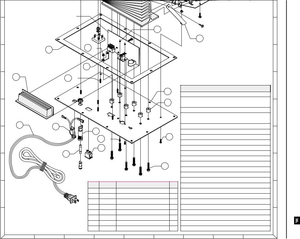
Amplifier Exploded View ................................................ |
6 |
Features.......................................................................... |
2 |
Parts Lists....................................................................... |
7 |
Powered Sub Test Setup............................................... |
2 |
Revisions ...................................................................... |
10 |
Test Procedure............................................................... |
2 |
Printed Circuit Boards ................................................. |
11 |
Block Diagram ................................................................ |
4 |
Integrated Circuit Diagrams ......................................... |
15 |
Cabinet Assembly Exploded View................................. |
5 |
Schematic Diagrams ................................................... |
16 |
Packaging Exploded View ............................................. |
5 |
|
|
SPECIFICATIONS
Amplifier Power (RMS)* . . . . . . . . 250 Watts Total
35 x 3 @ 0.1% THD
23 x 1 @ 0.1% THD
100 x 1 @ 0.1% THD
Low Frequency Woofer (2) . . . . . . . |
SE6H 6-1/2" Poly-Cone Woofer |
|
Design . . . . . . . . . . . . . . |
Bass Reflex Enclosure |
|
Inputs . . . . . . . . . . . . . . |
RCA Phono plugs at “Source”; |
|
|
13 pin Din plug to Subwoofer |
|
Outputs . . . . . . . . . . . . . |
(4) |
Full range Speaker; |
|
(1) |
Subwoofer |
Crossover Frequency Subwoofer (-6dB) . . . |
150Hz |
|
Frequency Response (-6dB)
System . . . . . . . . . . . . . 35Hz - 20kHz
Subwoofer . . . . . . . . . . . . 35Hz - 150Hz
External Dimensions |
|
|
Height |
. . . . . . . . . . . . . |
15-3/4" (400mm) |
Width |
. . . . . . . . . . . . . |
8-1/2" (216mm) |
Depth |
. . . . . . . . . . . . . |
20" (508mm) |
Weight . |
. . . . . . . . . . . . . |
40 lbs. (18.2 kg) |
JBL continually strives to improve its products. New materials, production methods and design refinements are introduced into existing models without notice as a routine expression of our design philosophy. For this reason, the Bass550 Subwoofer may differ in some respect from its published specifications and descriptions, but will always equal or exceed the original specifications unless otherwise stated.
1
Powered Subwoofer |
|
BASS550 |
|
|
|
FEATURES
The Bass550 powered subwoofer is part of the ESC550 System.
Amplifiers for five satellite speakers and subwoofer.
100 watt output.
Line level input exclusively from the “Source”.
User friendly “auto on” circuit. Signal sensing automatically turns the subwoofer on so you don't have to; the subwoofer is meant to be left “on” without continually using the power switch.
Variable level control.
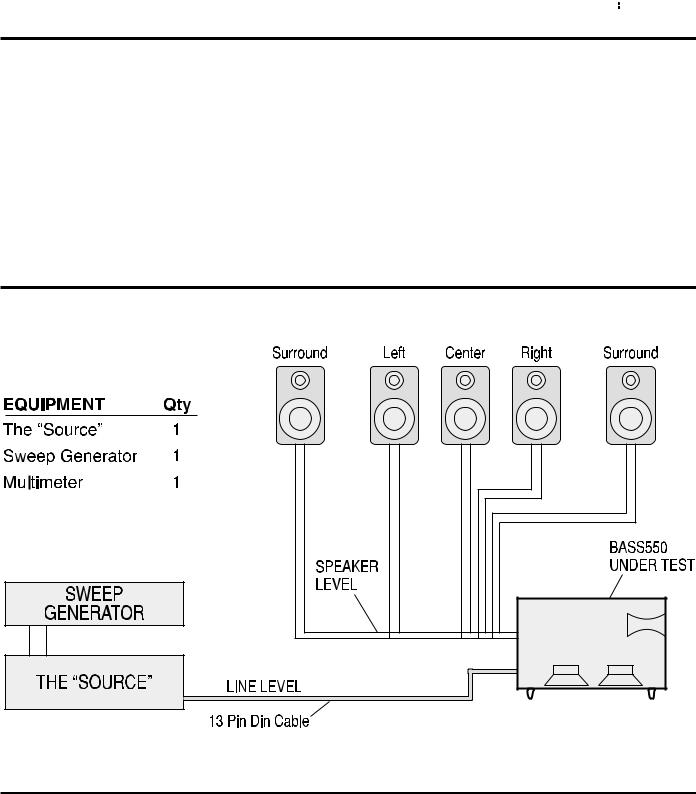
BASS550 POWERED SUBWOOFER TEST SETUP
TEST PROCEDURE
Equipment needed:
The “Source” AM/FM turner/CD player w/ remote control.
Function/signal generator/sweep generator.
Multimeter.
Cable - Phono plugs (RCA) and speaker cables.
RCA Y-cable
Subwoofer, General Function
1)Connect both right and left phono jack (RCA) inputs to signal generator and the “Source” Tape/Aux. input jacks. Use Y-cable if necessary from mono source.
2)Connect Bass550 subwoofer to the “Source” with supplied 13 pin Din cable.
2

Powered Subwoofer
3)Plug in subwoofer, turn power switch on; red LED should light.
4)Turn on generator, adjust to 100 mV, 50 Hz.
5)Push “power” button on the “Source”, (display should now be active); press “Tape/Aux” button, adjust volume (on Source) so display reads “VOLUME 30”.
6)Turn up level control on subwoofer full clockwise.
7)LED on subwoofer should cycle to green; bass response should be heard and felt from port tube opening.
Subwoofer, Sweep Function
1)Follow steps 1-7 above, using a sweep generator as a signal source.
2)Sweep generator from 20Hz to 300Hz. Listen to the cabinet and drivers for any rattles, clicks, buzzes or any other noises. If any unusual noises are heard, remove driver and test.
Subwoofer, Driver Function
1)Remove one or both drivers from cabinet; remove + and - wire clips.
2)Check DC resistance of driver; it should be approximately 5.8 ohms.
3)Connect a pair of speaker cables to driver terminals. Cables should be connected to an integrated amplifier fed by a signal generator. Turn on generator and adjust so that speaker level output is 4.0V.
4)Sweep generator from 20Hz to 1kHz. Listen to driver for any rubbing, buzzing, or other unusual noises.
BASS550
System, General Function
1)Connect Bass550 subwoofer to the “Source” with supplied 13 pin Din cable.
2)Attach all five satellite speakers to the supplied speaker cables, terminating in a molex connector plugged into the subwoofer.
3)Plug in Bass550 subwoofer, turn power switch on; red LED should light.
4)Push “power” button on the “Source”; (display should now be active).
5)Toggle “surround mode” button on front panel or with remote control until “NORMAL” appears.
6)Toggle “rear speaker”button on front panel until “REAR SPEAKERS” is displayed in upper left corner.
7)Adjust volume (on Source) so display reads “VOLUME 30”.
8)Using remote control, press “TONE” button.
9)White noise should be heard, cycling from Left, Center, Right and Rear speakers in succession.
10)Press “TONE” button again to halt test.
3
Powered Subwoofer |
|
BASS550 |
|
|
|
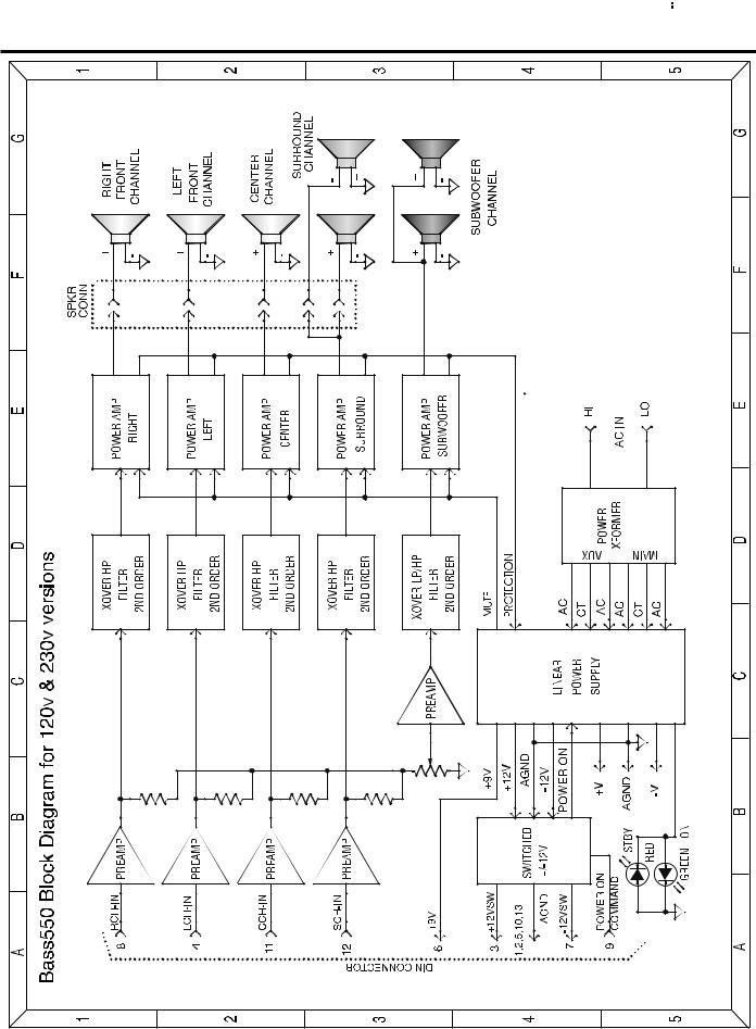
BASS550 (120v US & 230v European Versions) BLOCK DIAGRAM
4
Powered Subwoofer |
|
BASS550 |
|
|
|
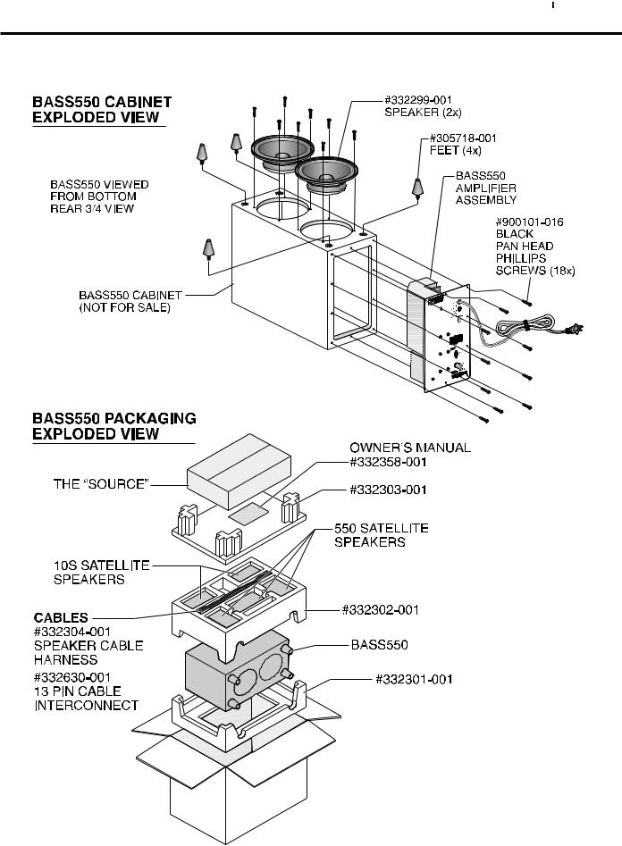
BASS550 CABINET ASSEMBLY & PACKAGING EXPLODED VIEWS
5
6
A B C D E F G H I
1 |
|
|
|
|
|
|
|
31 2x |
1 |
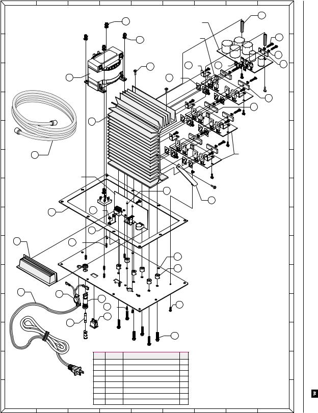
Bass550 Amplifier |
20 5x |
|
|
Power Supply PCB |
|
|
|||
|
|
|
|
|
|
||||
|
|
|
|
|
|
|
|
||
|
Exploded View |
|
|
|
|
|
|
|
|
|
|
22 |
5x |
Power Amp Subwoofer |
|
|
26 8x |
||
|
|
|
PCB 1166 |
|
|
|
|
||
2 |
|
|
|
|
|
|
|
2 |
|
|
|
|
|
|
|
|
|
||
|
|
BL |
|
|
|
|
|
|
21 10x |
|
|
1733 |
|
|
|
|
|
|
|
|
|
- |
|
|
|
|
|
|
|
|
|
|
27 17x |
3 |
6x |
30 3x |
|
7 |
|
|
|
|
|
|
|||||
3 |
12 |
|
|
|
29 12x |
|
|
|
3 |
|
|
|
|
|
|
|
|
1 |
4x |
4 |
|
|
|
|
|
|
2 |
2x |
4 |
|
|
11 |
|
|
|
|
|
|
|
5 |
|
|
|
|
|
|
|
|
5 |
32
6
Preamp & Crossover PCB
7
16
8
17 |
25 6x |
9
10
10 |
23 |
|
11
8
12
13
14
Power Amp PCB 1165
18 2x
4
19 2x
5
|
|
|
6 |
|
|
|
13 6x |
9 |
|
|
|
|
24 2x |
|
26 6x |
|
|
|
|
|
14 |
|
|
|
|
28 6x |
|
Ref # |
Part No. |
Description |
Qty. |
1 |
BR1187 |
Alum. Bar 4.8x12.7x40mm |
4 |
2 |
BR1386 |
Transistor Bar TO-218 |
2 |
3 |
BR1395 |
Bracket Power Support |
6 |
4 |
BR1411 |
Bracket Support 60 Deg |
1 |
5 |
BR1421 |
Bracket "L" 0.9"x0.9" |
1 |
6 |
BR1423 |
Front Plate |
1 |
7 |
BR1495 |
Alum. Bar |
1 |
8 |
FS1078 |
Fuse 6A 250V 3AG Slow Blow |
1 |
Ref # |
Part No. |
|
Description |
Qty. |
|
9 |
FH1002 |
|
Fuse Holder 1/4x1-1/4 |
1 |
|
10 |
XX1174 |
|
AG AC Cord 6ft. UL/CSA aprov. 120v |
1 |
|
|
WI1597 |
|
AG AC Cord 6ft. UL/CSA aprov. 230v |
1 |
|
11 |
HS1142 |
|
Heatsink Internal |
1 |
|
12 |
MI1151 |
|
AG Power Transformer 120v |
1 |
|
|
M1159 |
|
AG Power Transformer 230v |
1 |
|
13 |
ST1025 |
|
Round Spacer 1/2x3/8 length |
6 |
|
14 |
SW1075 |
|
JR Switch Rocker 2P2T Snap-I |
1 |
|
15 |
XX1259 |
|
Knob Black (not shown) |
1 |
|
16 |
XX1269 |
|
Gasket |
1 |
|
17 |
XX1276 |
|
Plastic Cover |
1 |
|
18 |
NU1059 |
|
Nut 4-40 Keps-Thr. Hexag. Zinc |
2 |
|
19 |
NU1057 |
|
Nut 6-32 Keps Zinc Hexag. |
2 |
|
20 |
NU1049 |
|
Nut 8-32x1/4 Keps Hexag. |
5 |
|
21 |
WA1049 |
|
Washer Ext. Tooth #6 Zinc |
10 |
|
22 |
WA1080 |
|
Washer Flat #8 Steel Zinc |
5 |
|
23 |
XX1250 |
|
Strain Relief SPT-1 Black |
1 |
|
24 |
SC1253 |
|
Screw 4-40x3/8 Pan Phillips |
2 |
|
25 |
SC1274 |
|
Screw 5-20x1/4 Thread Form. Z. |
6 |
|
26 |
SC1192 |
|
Screw 6-32x3/4 Cutt-Thr. Hex. |
8 |
|
27 |
SC1194 |
|
Screw 6-32x3/8 Tapt-Thr Hex. |
17 |
|
28 |
SC1282 |
|
Screw 10-32x7/8 Pan-Torx Hd. |
6 |
|
29 |
SP1073 |
|
Sil Pad TO-3P 1/0"x0.75" |
12 |
|
30 |
SP1072 |
|
Sil Pad TO-220 0.750" |
3 |
|
31 |
ST1024 |
|
1/4 Hex Fem. Standoff 1-1 |
2 |
|
32 |
332630-001 |
|
13 Pin Interconnect Cable |
1 |
|
6
7
8
9
10
11
12
13
14
A B C D E F G H I
Subwoofer Powered
View Exploded Amplifier Bass550
Bass550

|
A |
B |
C |
|
D |
E |
|
F |
|
G |
H |
|
|
I |
|
Powered |
|
|
|
|
|
|
|
|
|
|
|
|
31 |
2x |
|
|
|
1 |
|
|
|
|
|
|
|
|
|
|
|
|
1 |
Subwoofer |
||
Bass550 Amplifier |
|
|
20 5x |
|
|
Power Supply PCB |
|
|
|
|
|
|||||
|
|
|
|
|
|
|
|
|
|
|
||||||
|
Exploded View |
|
|
|
|
|
|
|
|
|
|
|
||||
|
|
|
|
|
|
|
|
|
|
|
|
|
|
|||
|
|
|
|
|
|
|
|
|
|
|
|
|
|
|
|
|
|
|
|
|
|
22 |
5x |
Power Amp Subwoofer |
|
|
|
|
26 8x |
|
|
||
|
|
|
|
|
|
PCB 1166 |
|
|
|
|
|
|
|
|
||
2 |
|
|
|
|
|
|
|
|
|
|
|
|
|
2 |
|
|
|
|
|
|
|
|
|
|
|
|
|
|
|
|
|
||
|
|
|
|
1 |
|
|
|
|
|
|
|
|
|
|
|
|
|
|
|
|
15 |
|
|
|
|
|
|
|
|
|
|
|
|
|
|
|
|
BL |
42 |
|
|
|
|
|
|
|
|
21 10x |
|
|
|
|
|
|
- |
|
|
|
|
|
|
|
|
|
|
||
|
|
|
|
IN |
S |
|
|
|
|
|
|
|
|
|
|
|
|
|
|
0 |
1733.Y. WOOD, |
IGNAL21 |
|
|
|
|
|
|
|
|
|
|
|
|
|
|
11096 |
0 |
|
|
|
|
|
|
|
|
|
|
||
|
|
|
|
TRANSFORMER |
|
|
|
|
|
|
|
|
|
|
|
|
|
|
|
|
84 |
|
|
|
|
|
|
|
|
|
|
|
|
|
|
|
|
42 |
|
|
|
|
|
|
|
|
|
|
|
|
|
|
|
|
0 |
|
|
|
|
|
|
|
|
|
7 |
|
|
|
|
|
|
|
|
27 17x |
3 |
6x |
30 3x |
|
|
|
|
|||
3 |
|
|
12 |
|
|
|
|
29 12x |
|
|
|
|
|
|
3 |
|
|
|
|
|
|
|
|
|
|
|
|
|
|
1 |
4x |
|
|
4 |
|
|
|
|
|
|
|
|
|
|
2 |
2x |
|
|
4 |
|
|
|
|
11 |
|
|
|
|
|
|
|
|
|
|
|
|
|
5 |
|
|
|
|
|
|
|
|
|
|
|
|
|
|
5 |
|
|
|
32 |
|
|
|
|
|
|
|
|
Power Amp PCB 1165 |
|
Bass550 |
|||
6 |
|
|
|
|
|
|
|
|
|
|
|
|
|
|
6 |
|
|
|
Preamp & Crossover PCB |
|
|
|
|
|
|
|
|
|
|
|
|
||
|
|
|
|
|
|
|
|
|
|
|
|
|
|
|
|
|
7 |
|
|
|
|
|
|
|
18 2x |
|
|
|
|
|
|
7 |
Amplifier |
|
|
|
|
|
|
|
|
|
|
4 |
|
|
|
|
|
|
|
|
16 |
19 2x |
|
|
|
|
|
|
|
|
|
|
|
||
|
|
|
|
|
|
|
|
|
|
|
|
|
Exploded |
|||
|
|
|
|
|
|
|
|
|
|
|
|
|
|
|
||
8 |
|
|
|
|
|
|
|
|
|
|
|
|
|
|
8 |
|
|
|
|
5 |
|
|
|
|
|
|
|
|
|
|
|
|
|
|
17 |
|
25 6x |
|
|
|
|
|
|
|
|
|
|
|
|
|
|
|
|
|
|
|
|
|
|
|
|
|
|
|
View |
||
9 |
|
|
|
|
|
|
|
|
Ref # |
Part No |
Description |
|
|
Qty |
9 |
|
|
|
|
|
|
|
|
|
|
|
|
|
|||||
6
6
Preamp & Crossover PCB
7 |
|
18 2x |
|
16 |
19 2x |
|
|
|
8 |
|
|
|
|
5 |
17 |
|
25 6x |
9 |
|
|
6
13 6x
10
|
10 |
23 |
|
|
|
|
|
|
|
|
|
|
|
9 |
|
|
|
11 |
|
|
24 2x |
|
26 6x |
|
|
|
|
||
|
|
|
14 |
|
|
|
|
8 |
|
|
|
12 |
|
|
|
28 6x |
|
|
|
Ref # |
Part No. |
Description |
Qty. |
13 |
|
1 |
BR1187 |
Alum. Bar 4.8x12.7x40mm |
4 |
|
2 |
BR1386 |
Transistor Bar TO-218 |
2 |
|
|
|
||||
|
|
3 |
BR1395 |
Bracket Power Support |
6 |
|
|
4 |
BR1411 |
Bracket Support 60 Deg |
1 |
|
|
5 |
BR1421 |
Bracket "L" 0.9"x0.9" |
1 |
|
|
6 |
BR1423 |
Front Plate |
1 |
14 |
|
7 |
BR1495 |
Alum. Bar |
1 |
|
|
||||
|
|
8 |
FS1078 |
Fuse 6A 250V 3AG Slow Blow |
1 |
4
Ref # |
Part No. |
|
Description |
Qty. |
|
9 |
FH1002 |
|
Fuse Holder 1/4x1-1/4 |
1 |
|
10 |
XX1174 |
|
AG AC Cord 6ft. UL/CSA aprov. 120v |
1 |
|
|
WI1597 |
|
AG AC Cord 6ft. UL/CSA aprov. 230v |
1 |
|
11 |
HS1142 |
|
Heatsink Internal |
1 |
|
12 |
MI1151 |
|
AG Power Transformer 120v |
1 |
|
|
M1159 |
|
AG Power Transformer 230v |
1 |
|
13 |
ST1025 |
|
Round Spacer 1/2x3/8 length |
6 |
|
14 |
SW1075 |
|
JR Switch Rocker 2P2T Snap-I |
1 |
|
15 |
XX1259 |
|
Knob Black (not shown) |
1 |
|
16 |
XX1269 |
|
Gasket |
1 |
|
17 |
XX1276 |
|
Plastic Cover |
1 |
|
18 |
NU1059 |
|
Nut 4-40 Keps-Thr. Hexag. Zinc |
2 |
|
19 |
NU1057 |
|
Nut 6-32 Keps Zinc Hexag. |
2 |
|
20 |
NU1049 |
|
Nut 8-32x1/4 Keps Hexag. |
5 |
|
21 |
WA1049 |
|
Washer Ext. Tooth #6 Zinc |
10 |
|
22 |
WA1080 |
|
Washer Flat #8 Steel Zinc |
5 |
|
23 |
XX1250 |
|
Strain Relief SPT-1 Black |
1 |
|
24 |
SC1253 |
|
Screw 4-40x3/8 Pan Phillips |
2 |
|
25 |
SC1274 |
|
Screw 5-20x1/4 Thread Form. Z. |
6 |
|
26 |
SC1192 |
|
Screw 6-32x3/4 Cutt-Thr. Hex. |
8 |
|
27 |
SC1194 |
|
Screw 6-32x3/8 Tapt-Thr Hex. |
17 |
|
28 |
SC1282 |
|
Screw 10-32x7/8 Pan-Torx Hd. |
6 |
|
29 |
SP1073 |
|
Sil Pad TO-3P 1/0"x0.75" |
12 |
|
30 |
SP1072 |
|
Sil Pad TO-220 0.750" |
3 |
|
31 |
ST1024 |
|
1/4 Hex Fem. Standoff 1-1 |
2 |
|
32 |
|
|
|
13 Pin Interconnect Cable |
1 |
332630-001 |
|
||||
|
|
|
|
|
|
A B C D E F G H I
6
7
8
9
10
11
12
13
14
View Exploded Amplifier Bass550
Bass550
 Loading...