


 BASS20
Powered Subwoofer
SERVICE MANUAL
JBL Consumer Products Inc.
80 Crossways Park West
Woodbury, N.Y. 11797
1-800-336-4JBL in the USA
A Harman International Company
Part No.: 1112-JBLBASS20

Powered Subwoofer  BASS20
TABLE OF CONTENTS
Specifications ................................................................. |
1 |
Cabinet Assembly Exploded View |
.................................7 |
Features.......................................................................... |
1 |
Parts Lists....................................................................... |
8 |
Powered Sub Test Setup............................................... |
2 |
Packaging View............................................................ |
10 |
Test Procedure............................................................... |
3 |
Printed Circuit Boards ................................................. |
11 |
Important Service Note .................................................. |
4 |
Integrated Circuit Diagram ........................................... |
13 |
Block Diagram ................................................................ |
5 |
Schematic Diagrams ................................................... |
14 |
Amplifier Exploded View ................................................ |
6 |
|
|
SPECIFICATIONS
Amplifier Power (RMS) . . . . . . . 150 Watts
Low Frequency Woofer (2) . . . . . . 8 1/2"
Design. . . . . . . . . . . . . Bass reflex enclosure, Grey or White
Inputs . . . . . . . . . . . . . Line Level and Speaker Level
Outputs . . . . . . . . . . . . Full Range Speaker
Crossover Frequency . . . . . . . . 120Hz
Frequency Response . . . . . . . . 40Hz - 120Hz (+/-3dB)
External Dimensions (Inches)
Height . . . . . . . . . . . . . 17-3/4"
Width . . . . . . . . . . . . . 10"
Depth . . . . . . . . . . . . . 24"
External Dimensions (mms)
Height . . . . . . . . . . . . . 451
Width . . . . . . . . . . . . . 254
Depth . . . . . . . . . . . . . 610
Weight. . . . . . . . . . . . . 42lbs (19.1kg)
FEATURES
The Bass20 powered subwoofer is part of the SCS120 or |
Line level or Speaker level inputs, outputs for full range |
|
|
MUSIC 20 System. |
satellite speakers. |
|
150 watt output. |
User friendly “auto on” circuit. Signal sensing |
|
|
automatically turns the subwoofer on so you don't have |
|
Variable level control. |
to; the subwoofer is meant to be left “on” without |
|
|
continual use of the power switch. |
1

Powered Subwoofer |
|
BASS20 |
|
|
|
BASS 20 POWERED SUB WOOFER TEST SETUP
JBL continually strives to improve its products. New materials, production methods and design refinements are introduced into existing models without notice as a routine expression of our design philosophy. For this reason, Bass Series loudspeakers may differ in some respect from their published specifications and descriptions, but will always equal or exceed the original specifications unless otherwise stated.
2

Powered Subwoofer |
|
BASS20 |
|
|
|
TEST PROCEDURE
Equipment Needed:
Function generator/signal generator/sweep generator
Integrated Amplifier
Multimeter
Cables - Line level (RCA) and Speaker cables
UUT = Unit Under Test
General Function
1.Connect both left and right line level inputs (RCA) to signal generator and UUT. Use Y-cable if necessary from mono source.
2.Turn on generator and adjust to 100mV, 50 Hz.
3.Plug in UUT; red LED should be ON. Turn power switch to the ON or AUTO position and turn LEVEL control full clockwise.
4.Green LED should light, immediate bass response should be heard and felt from port tube openings.
5.Turn off generator, turn unit to OFF, disconnect RCA cables.
6.Connect two pairs of speaker cables to high level input terminal on UUT. Cables should be connected to an integrated amplifier fed by the signal generator. Observe polarity of speaker cables.
7.Turn on generator and adjust so that speaker level output is 2.5V, 50 Hz.
8.Turn power switch to the ON or AUTO position and turn LEVEL control full clockwise.
9.Green LED should light, immediate bass response should be heard and felt from port tube opening.
Sweep Function
1.Follow steps 1-4 above, using a sweep generator as a signal source.
2.Sweep generator from 20Hz to 300Hz. Listen to the cabinet and drivers for any rattles, clicks, buzzes or any other noises. If any noises are heard, remove driver and test.
Driver Function
1.Remove one or both drivers from cabinet; remove + and - wire clips.
2.Check DC resistance of driver; it should be 4.2 ohms.
3.Connect a pair of speaker cables to driver terminals. Cables should be connected to an integrated amplifier fed by a signal generator. Turn on generator and adjust so that speaker level output is 5.0V.
4.Sweep generator from 20Hz to 1kHz. Listen to driver for any rubbing, buzzing or other unusual noises.
SERVICE NOTE (120v Version only)
Even though the Bass20 seems to have an on/off power switch, in fact the switch does not switch the main power off to the amp assembly, even in the OFF position. All AC and DC voltages within the amplifier are still active, so for safety concerns the AC power cord should be unplugged before any servicing begins.
3
Powered Subwoofer |
|
BASS20 |
|
|
|
IMPORTANT SERVICE NOTE:
Amplifier assemblies with serial numbers less than 11757 should be modified for safe operation. Examine amplifier as follows (serial #11756 or lower) to determine if a factory modification has taken place:
1.Unplug and remove amp assembly; (12) #8 x 3/4" screws.
2.Lift and examine the main (large) amp board, solder (green) side of the board.
3.Look for the presence of two large resistors (1k, 3 Watt or 470 ohm, 1Watt) directly underneath the two large filter caps on the opposite side of the board.
4.If these resistors are present, the unit has been modified.
5.If they are missing, the unit should be modified before future use, regardless of what the initial service concern was. To continue without modification may result in a hazardous condition.
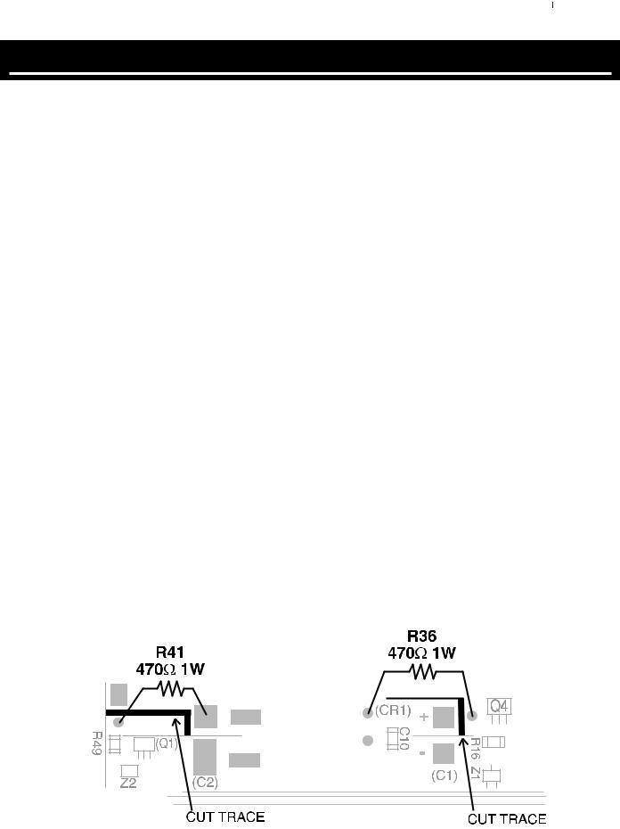
MODIFICATION:
1.Cut tie wraps to bundled wire assemblies for easier access. Circuit board does not have to be removed from heatsink.
2.R36: See drawing: cut trace connecting Q4 collector and main C1 (+) pad.
3.Create solderable surface on PCB, (on Q4 side of cut) by scraping the green mask from board with Exacto knife or similar tool.
4.Attach R36, 470 1W resistor (JBL #RS2180) to new surface and cathode side of CR1. Resistor should "stand off" from PCB; secure with RTV or epoxy if desired.
5.R41: See drawing; cut trace connecting Q1 collector and main C2 (-) pad.
6.Create solderable surface on PCB, (just above R49) by scaping the green mask from the board with Exacto knife or similar tool.
7.Attach R41, 470W 1W resistor (JBL #RS2180) to new surface and C1 (-) pad. Resistor should "stand off" from PCB; secure with RTV or epoxy if desired.
8.Retie cables with tie wraps.
9.Cut and insert two in-line fuse holders (JBL #155020A) with 4A fuses (JBL #312004); one in each positive wire leading to woofer terminal, close to the amplifier assembly.
10.Replace amp assembly in cabinet.
4
 Loading...