


 Loading...
Owners Manual
305PMKII |
306PMKII |
308PMKII |
LSR310S |
5" Powered |
6" Powered |
8" Powered |
10" Powered |
Studio Monitor |
Studio Monitor |
Studio Monitor |
Studio Subwoofer |

Product Registration
Thank you for your purchase of JBL 3 Series Studio Monitors
To receive important information as it becomes available, please take a moment to register your 3 Series speakers at www.jblpro.com/registration.
2

Table of Contents |
|
Section 1: Important Safety Instructions ............................................................................................................... |
4 |
Section 2: Introduction ........................................................................................................................................... |
5 |
JBL Linear Spatial Reference (LSR) Design ................................................................................................... |
5 |
Image Control Waveguide .............................................................................................................................. |
5 |
305P, 306P, and 308P MkII Features .............................................................................................................. |
5 |
LSR310S Powered Studio Subwoofer Features............................................................................................. |
6 |
JBL Professional Reliability ............................................................................................................................ |
6 |
Section 3: Setting Up Your System ........................................................................................................................ |
7 |
Each 3 Series Carton Includes the Following Items: ...................................................................................... |
7 |
Unpacking....................................................................................................................................................... |
7 |
Placement....................................................................................................................................................... |
7 |
Audio Connections ......................................................................................................................................... |
9 |
LSR310S Powered Studio Subwoofer Connections ...................................................................................... |
9 |
Power Connections ........................................................................................................................................ |
9 |
Making Sound................................................................................................................................................. |
9 |
Section 4: 305P, 306P, and 308P MkII Powered Studio Monitors....................................................................... |
10 |
Features........................................................................................................................................................ |
10 |
Input Panel.................................................................................................................................................... |
11 |
Audio Connections ....................................................................................................................................... |
11 |
Section 5: LSR310S Powered Studio Subwoofer................................................................................................ |
12 |
Features........................................................................................................................................................ |
12 |
Input Panel.................................................................................................................................................... |
13 |
Audio Connections ....................................................................................................................................... |
14 |
Setting the Subwoofer Level ........................................................................................................................ |
14 |
Placement and Polarity Setting .................................................................................................................... |
14 |
Crossover Settings and Bass Management ................................................................................................ |
15 |
Surround Sound Systems and LFE .............................................................................................................. |
15 |
Section 6: System Connections ........................................................................................................................... |
16 |
Two Channel Systems .................................................................................................................................. |
16 |
Surround Sound Systems............................................................................................................................. |
17 |
Section 7: Troubleshooting................................................................................................................................... |
18 |
Section 8: Specifications ...................................................................................................................................... |
19 |
Section 9: JBL Service Contact Information........................................................................................................ |
20 |
Section 10: Product Warranty Information .......................................................................................................... |
21 |
3
Section 1: Important Safety Instructions
1.READ these instructions.
2.KEEP these instructions.
3.HEED all warnings.
4.FOLLOW all instructions.
5.DO NOT use this apparatus near water.
6.CLEAN ONLY with dry cloth.
7.DO NOT block any ventilation openings. Install in accordance with the manufacturer’s instructions.
8.DO NOT install near any heat sources such as radiators, heat registers, stoves, or other apparatus (including ampliiers) that produce heat.
9.DO NOT defeat the safety purpose of the polarized or grounding type plug. A polarized plug has two blades with one wider than the other. A grounding type plug has two
blades and a third grounding prong. The wider blade or the third prong are provided for your safety. If the provided plug does not it into your outlet, consult an electrician for replacement of the obsolete outlet.
10.PROTECT the power cord from being walked on or pinched, particularly at plugs, convenience receptacles, and the point where they exit from the apparatus.
11.ONLY USE attachments/accessories speciied by the manufacturer.
USE ONLY with a cart, stand, tripod, bracket, or table speciied by the
12.manufacturer, or sold with the apparatus. When a cart is used, use caution when moving the cart/apparatus combination to avoid injury from tip-over.
13.UNPLUG this apparatus during lightning storms or when unused for long periods of time.
14.REFER all servicing to qualiied service personnel. Servicing is required when the apparatus has been damaged in any way, such as power-supply cord or plug is damaged, liquid has been spilled or objects have fallen into the apparatus, the apparatus has been exposed to rain or moisture, does not operate normally, or has been dropped.
15.DO NOT expose this apparatus to dripping or splashing and ensure that no objects illed with liquids, such as vases, are placed on the apparatus.
16.To completely disconnect this apparatus from the AC Mains, disconnect the power supply cord plug from the AC receptacle.
17.Where the mains plug or an appliance coupler is used as the disconnect device, the disconnect device shall remain readily operable.
18.DO NOT overload wall outlets or extension cords beyond their rated capacity as this can cause electric shock or ire.
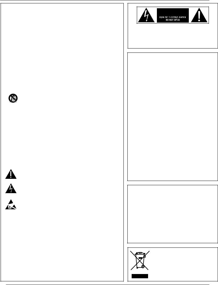
The exclamation point, within an equilateral triangle, is intended to alert the user to the presence of important operating and maintenance (servicing) instructions
in the literature accompanying the product.
The lightning lash with arrowhead symbol within an equilateral triangle is
intended to alert the user to the presence of uninsulated “dangerous voltage” within the product’s enclosure that may be of suficient magnitude to constitute
a risk of electrical shock to persons.
ESD Warning: The icon to the left indicates text regarding potential danger
associated with the discharge of static electricity from an outside source (such as human hands) into an integrated circuit, often resulting in damage to the
circuit.
WARNING: To reduce the risk of ire or electrical shock, do not expose this apparatus to rain or moisture.
WARNING: No naked lame sources – such as lighted candles – should be placed on the product.
WARNING: Equipment shall be connected to a MAINS socket outlet with a protective earthing connection.
CAUTION: To reduce the risk of electric shock, grounding of the center pin of this plug must be maintained.
WARNING: This product is intended to be operated ONLY from the voltages listed on the back panel or the recommended, or included, power supply of the product. Operation from other voltages other than those indicated may cause irreversible damage to the product and void the products warranty. The use of AC Plug Adapters is cautioned because it can allow the product to be plugged into voltages in which the product was not designed to operate. If you are unsure of the correct operational voltage, please contact your local distributor and/or
retailer. If the product is equipped with a detachable power cord, use only the type provided, or speciied, by the manufacturer or your local distributor.
WARNING: Do Not Open! Risk of Electrical Shock. Voltages in
this equipment are hazardous to life. No user-serviceable parts inside. Refer all servicing to qualiied service personnel.
Place the equipment near a main power supply outlet and make sure that you can easily access the power breaker switch.
FCC AND CANADA EMC COMPLIANCE
INFORMATION:
This device complies with part 15 of the FCC Rules. Operation is subject to the following two conditions:
(1)This device may not cause harmful interference, and
(2)this device must accept any interference received, including
interference that may cause undesired operation.
NOTE: This equipment has been tested and found to comply with the limits for a Class B digital device, pursuant to part 15 of the FCC Rules. These limits are designed to provide reasonable protection against harmful interference in a residential installation. This equipment generates, uses and can radiate radio frequency energy and, if not installed and used in accordance with the instructions, may cause harmful interference to radio communications. However, there is no guarantee that interference will not occur in a particular installation. If this equipment does cause harmful interference to radio or television reception, which can be determined by turning the equipment off and on, the user is encouraged to try to correct the interference by one or more of the following measures:
•Reorient or relocate the receiving antenna.
•Increase the separation between the equipment and receiver.
•Connect the equipment into an outlet on a circuit different from that to which the receiver is connected.
•Consult the dealer or an experienced radio/TV technician for help.
Approved under the veriication provision of FCC Part 15 as a Class
B Digital Device.
CAUTION: Changes or modiications not expressly approved by the manufacturer could void the user’s authority to operate this device.
CAN ICES-3 (B)/NMB-3(B)
EU COMPLIANCE INFORMATION:
Hereby, Harman Professional declares that the equipment type JBL 305P MKII, 306P MKII, 308P MKII, are in compliance with the following:
•European Union Low Voltage Directive 2014/35/EU
•European Union EMC Directive 2014/30/EU
•European Union Restriction of Hazardous Substances Recast
(RoHS2) Directive 2011/65/EU
•European Union Registration, Evaluation, Authorization and
Restriction of Chemicals (REACH) Directive 1907/2006
The full text of the EU declaration of conformity is available at the following Internet address: http://www.jblpro.com/www/productsupport/downloads
WEEE NOTICE:
This appliance is labeled in accordance with
European Directive 2012/19/EU concerning waste of electrical and electronic equipment (WEEE).
This label indicates that this product should not be disposed of with household waste. It should be deposited at an appropriate facility to enable recovery and recycling.
4

Section 2: Introduction
Congratulations on your purchase of JBL Professional 3 Series Studio Monitors. The 3 Series meet JBL’s high standards for accuracy and long-term reliability in demanding professional applications. All 3 Series models incorporate JBL Professional transducer and network technologies to provide accurate frequency response, exceptional low frequency extension and high SPL capability. JBL Linear Spatial Reference (LSR) design ensures greater accuracy at the mix position in acoustically varied workspaces and production environments. Additionally, each speaker is equipped to interface with a range of signal sources, including high-output professional audio equipment.
JBL LINEAR SPATIAL REFERENCE (LSR) DESIGN
Because listening environments vary, JBL designed the 3 Series system using Linear Spatial Reference design criteria that improve accuracy at the listening position in a broad range of rooms. The key to accuracy is ensuring that not only the on-axis sound is neutral, but also the relected sound reaching the mix position is neutral.
While most manufacturers take only a single on-axis measurement of the speaker’s performance, Linear Spatial Reference design criteria requires 72 measurements, taken 360 degrees around the speaker, yielding 1,200 times more data. This data is used in the design of critical system components, enabling JBL to engineer complete systems that deliver smooth off-axis response. The result: clear, accurate sound at the listening position in any room.
IMAGE CONTROL WAVEGUIDE
JBL’s revolutionary Image Control Waveguide gives the 3 Series Powered Studio Monitors remarkable imaging, a wide soundstage, and a solid “phantom center”. Subtle details can be heard, even in a dense mix. As an added beneit, the Image Control Waveguide provides a broad “sweet spot”, so you don’t have to be seated directly in front of the speakers to hear accurate and natural and open sound.
305P, 306P, AND 308P MKII FEATURES
3 Series MkII models include a range of features to meet the needs of demanding audio production applications:
•The magnetically-shielded low frequency transducers in MkII models, equipped with 1.5" voice coils and robust motor structures ine tuned for increased linearity, deliver excellent low frequency performance. By reducing thermal-related effects, the 3 Series MkII Studio Monitors and LSR310S Subwoofer sound the same at low, medium, and high levels. The woofers are magnetically shielded to prevent interference with magnetically sensitive displays and equipment. The woofer’s self-repairing dust dome is resistant to dents caused by ingers or external objects.
•JBL’s patented Slip Stream™ low frequency port design works in concert with the woofer to produce deep bass response at any playback level. The double-lared shape of the port is precisely engineered for greater low frequency extension and reduced turbulence.
•The bi-ampliied design, with individual power ampliiers for the low frequency and high frequency transducers, uses eficient high-output Class-D integrated power ampliiers to provide high SPL (sound pressure level).
•Magnetically-shielded soft dome high frequency transducers with optimally damped materials improve transient response and minimize distortion. By reducing distortion in the lower operating range, where the ear is most sensitive, these transducers reduce ear fatigue.
•Balanced XLR and ¼" input connectors.
•+4dBu / -10dBV INPUT SENSITIVITY switch allows connection to consumer-grade or high-output professional equipment without danger of input overload.
•Detented VOLUME attenuator allows ine adjustment of levels for a broad range of signal sources.
•HIGH FREQUENCY TRIM control to adjust the high frequency response to taste or compensate for acoustically relective or absorptive listening environments.
•BOUNDARY EQ switch compensates for low-frequency acoustic anomalies that can occur when loudspeakers are in close proximity to walls.
5

LSR310S POWERED STUDIO SUBWOOFER FEATURES
Producing extended low frequency response into the 20Hz region, the LSR310S is the perfect match for the 3 Series MkII studio monitors. The LSR310S feature set includes:
•A Magnetically-shielded low frequency transducer, equipped with a 1.5" voice coil and robust motor structure for excellent low frequency performance. By reducing thermal-related effects, the 3 Series MkII Studio Monitors and LSR310S Subwoofer sound the same at low, medium, and high levels. The woofer is magnetically shielded to prevent interference with magnetically sensitive displays and equipment. The woofer’s self-repairing dust dome is resistant to dents caused by ingers or external objects.
•A custom-designed down-iring, high-excursion 10" woofer with additional bucking magnet.
•A 200 watt Class-D power ampliier with abundant output and dynamic headroom for the most demanding production styles.
•The patented Slip Stream low frequency port, designed to work in concert with the 3 Series MkII woofers for accurate bass response at all playback levels.
•A detented VOLUME control, making it easy to balance the LSR310S with the studio monitor system.
•Balanced XLR and ¼" input connectors.
•Two XLR output connectors to add the LSR310S to any studio monitor system and extend its low frequency response.
•A +4dBu / -10dBV INPUT SENSITIVITY switch for connection to consumer or high-output professional equipment without danger of input overload.
•Three CROSSOVER settings:
•80Hz – This setting implements highand low-pass ilters to create a seamless blend of the LSR310S with the 3 Series MkII studio monitors or other speaker system.
•XLF – This special setting activates a 120Hz high-pass ilter in conjunction with a low frequency tuning that approximates the tuning used in club playback systems. Using this setting, the bass output more than doubles.
•External – The external setting bypasses all iltering, allowing use of an external active crossover.
•A protective limiting circuit allows the subwoofer to operate continuously at full output without failure.
JBL PROFESSIONAL RELIABILITY
Prior to becoming a production-ready design, each 3 Series model is subjected to JBL’s tough 100-hour power test, in which the speaker is required to play continually at full output for 100 hours without failure. This demanding test ensures the 3 Series speakers will deliver years of reliable performance. To get the most out of the JBL 3 Series, please review this owner’s manual and keep it on hand for future reference. Also, please register your new speakers at www.jblpro.com/registration.
6

Section 3: Setting Up Your System
EACH 3 SERIES CARTON INCLUDES THE FOLLOWING ITEMS:
•One 3 Series MkII studio monitor or 3 Series subwoofer
•One power cord
•Quick setup guide
•Four peel-off rubber pads (305P, 306P, and 308P MkII models only)
UNPACKING
When removing a speaker from its packaging, we recommend the following procedure, which will prevent damage of the high frequency transducer:
305P, 306P, and 308P MkII models:
1.Remove the outer shipping carton, if one exists.
2.Place the inner carton on the loor with the top facing upwards.
3.Open the top of the box.
4.Without removing the internal packaging end-cap, gently rotate the carton so the open end rests on the loor and the bottom of the carton is facing you.
5.Gently lift the carton and allow the speaker and protective end-cap to slide out of the carton and remain on the loor.
6.Save the cartons and use the above procedure in reverse when you want to repack the units for shipment.
LSR310S subwoofer – The subwoofer weighs 19 kg (42 lbs). Unpacking the subwoofer does not require you to lift the subwoofer. However, you will need to rotate the subwoofer in the carton. If you are unable to perform the following steps without assistance, please request help from another person.
1.Remove the outer shipping carton, if one exists.
2.Place the carton on the loor with the bottom facing upward.
3.Open the bottom laps of the carton and remove any protective packing materials from the bottom of the subwoofer. Open the bag that protects the subwoofer to expose the subwoofer’s four feet.
4.Gently rotate the carton so the bottom is facing the loor and the four feet of the subwoofer are in contact with the loor.
5.Gently lift the carton and allow the subwoofer and protective packing materials to slide out and remain on the loor.
6.Remove the protective packing materials and documentation from the top of the subwoofer. Save the carton and use the above procedure in reverse when you want to repack the unit for shipment.
PLACEMENT
3 Series MkII Studio Monitors are designed to deliver exceptional imaging in any room. To get the most out of your speakers, follow these recommendations:
•Locate the four self-adhesive rubber pads supplied with the 305P, 306P, and 308P MkII speakers. Position and attach these to the bottom surface of the speaker close to each corner.
•Position each 305P, 306P, or 308P MkII Studio Monitor in a vertical orientation with the tweeter on top. Vertical orientation eliminates phase shift and acoustic cancellation of frequencies that can occur when the distance of the woofer to the ear is different from the distance of the tweeter to the ear.
•Angle the speakers so the high-frequency transducer in each speaker is aimed directly towards the ear of the listener.
7
Loading...