


TECHNICAL SPECIFICATIONS
Cinema ProPack 600 System
General |
|
Power Requirement: |
AC 120V 60Hz |
Contents: |
DCR600, DVD600, Programmable Master Remote Control, |
|
SCS135S speaker system, basic hookup wiring |
Carton Dimensions: |
Width: 37 inches (940mm) |
|
Height: 18 inches (457mm) |
|
Depth: 23 inches (584mm) |
Shipping Weight: |
95 lbs. (43.2kg) |
All features and specifications are subject to change without notice.
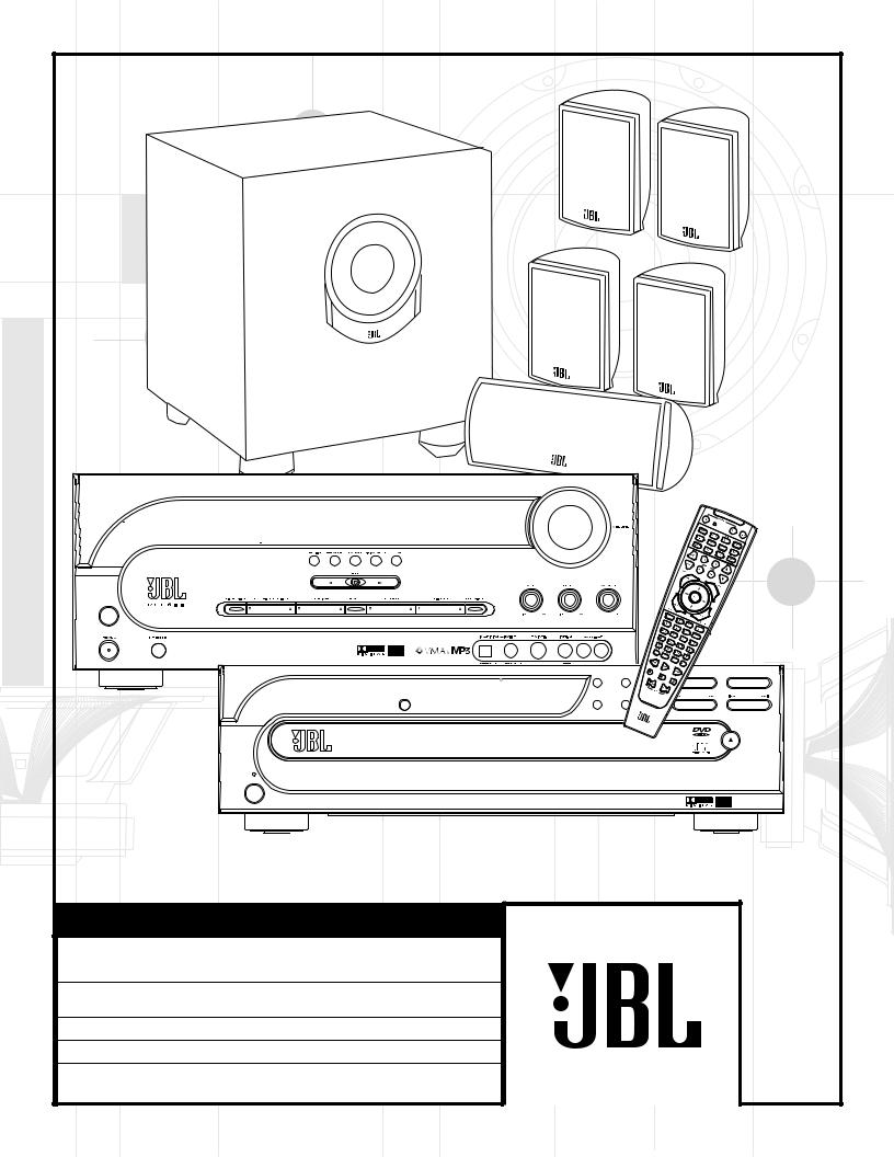
O W N E R ’ S G U I D E
M O D E L N U M B E R : C I N E M A P R O P A C K ™ 6 0 0
I n c l u d e s : D C R 6 0 0 , D V D 6 0 0 A N D S C S 1 3 5 S
D E S I G N G O A L : Re-create the excitement of the movies using high-performance separate components in one convenient package.
A U D I O / V I D E O R E C E I V E R : DCR600 with Dolby* Digital, DTS®, Logic 7®, VMAx® and MP3 Decoding
S O U R C E U N I T: DVD600 Five-Disc Carousel DVD/CD/CD-RW/VCD Changer
L O U D S P E A K E R S : SCS135S Six-Piece Home-Cinema Speaker System with 4 Satellites, 1 Center and 100-Watt Powered Subwoofer
P R O S O U N D
C O M E S H O M E ™
JBL Consumer Products
250 Crossways Park Drive, Woodbury, NY 11797
8500 Balboa Boulevard, Northridge, CA 91329
800-336-4JBL (4525) (USA only) www.jbl.com
©2001 JBL, Incorporated. JBL is a registered trademark of JBL, Incorporated.
Part No. ai5115
X+
0 +
Y2
0
M H Z
1
Dimmer |
4 |
D V D 6 0 0
power
X + 0 + Y 2 0 M H Z ” X + 0 +
 Y 2
Y 2
0
O W N E R ’ S G U I D E
M O D E L N U M B E R : C I N E M A P R O P A C K ™ 6 0 0
I n c l u d e s : D C R 6 0 0 , D V D 6 0 0 A N D S C S 1 3 5 S
D E S I G N G O A L : Re-create the excitement of the movies using high-performance separate components in one convenient package.
A U D I O / V I D E O R E C E I V E R : DCR600 with Dolby* Digital, DTS®, Logic 7®, VMAx® and MP3 Decoding
S O U R C E U N I T: DVD600 Five-Disc Carousel DVD/CD/CD-RW/VCD Changer
L O U D S P E A K E R S : SCS135S Six-Piece Home-Cinema Speaker System with 4 Satellites, 1 Center and 100-Watt Powered Subwoofer

|
|
|
|
|
|
|
|
|
|
|
|
|
|
|
|
|
|
|
|
|
|
|
|
|
|
|
|
|
|
|
|
|
|
|
|
|
|
|
|
|
|
4 |
SAFETY INFORMATION and UNPACKING |
|
53 |
|
|
|
Dolby Digital |
|
|
|
||||
|
|
|
|
5 |
GETTING STARTED |
|
53 |
|
|
|
DTS |
|
|
|
||||
|
|
|
|
5 |
|
What’s Included |
|
53 |
|
|
|
Selecting a Digital Source |
|
|
|
|||
|
|
|
|
5 |
|
Installing and Connecting the Equipment |
|
54 |
|
|
|
Digital Status Indicators |
|
|
|
|||
|
|
|
|
5 |
|
What We Recommend |
|
54 |
|
|
|
Night Mode |
|
|
|
|||
|
|
|
|
6 |
|
Quick Installation Diagrams |
|
54 |
|
|
|
Important Notes on Digital Playback |
|
|
|
|||
|
|
|
|
9 |
|
Where to Place the Speakers |
|
55 |
|
|
|
PCM Audio Playback |
|
|
|
|||
|
|
|
|
9 |
|
Speaker Mounting Options |
|
55 |
|
|
|
MP3 Audio Playback |
|
|
|
|||
|
|
|
|
10 |
|
Connecting the Speakers |
|
55 |
|
|
|
Operating the Tuner |
|
|
|
|||
|
|
|
|
10 |
|
Making the Audio Connections |
|
55 |
|
|
|
Station Selection |
|
|
|
|||
|
|
|
|
11 |
|
Making the Video Connections |
|
|
55 |
|
|
|
Preset Tuning |
|
|
|
||
|
|
|
|
11 |
|
Completing Setup |
|
56 |
|
|
|
Recalling Preset Stations |
|
|
|
|||
|
|
|
|
12 |
|
Quick Guide to Using the JBL Cinema ProPack 600 |
|
56 |
|
|
|
Tape Recording |
|
|
|
|||
|
|
|
|
13 |
|
DCR600 Front Panel Controls |
|
|
57 |
|
|
|
Operating the DVD600 DVD Changer |
|
|
|
||
|
|
|
|
15 |
|
DCR600 Front Panel Information Display |
|
57 |
|
|
|
Loading Discs |
|
|
|
|||
|
|
|
|
16 |
|
DCR600 Rear Panel Connections |
|
57 |
|
|
|
Playback Basics |
|
|
|
|||
|
|
|
|
|
|
|
|
|
|
|
|
|||||||
|
|
|
|
18 |
|
DVD600 Front Panel Controls |
|
58 |
|
|
|
Using the DVD Disc’s Menu |
|
|
|
|||
|
|
|
|
19 |
|
DVD600 Front Panel Information Display |
|
59 |
|
|
|
Using the Menu Bar |
|
|
|
|||
|
|
|
|
|
|
|
|
|
|
|
|
|
|
|
|
|
|
|
|
|
|
20 |
|
DVD600 Rear Panel Connections |
|
|
59 |
|
|
|
Menus and Controls |
|
|
|
|||
|
|
|
|
21 |
|
Remote Control |
|
59 |
|
|
|
Selecting Titles and Chapters |
|
|
|
|||
|
|
|
|
25 |
|
Remote Control Function Grid |
|
59 |
|
|
|
Changing Languages |
|
|
|
|||
|
|
|
|
27 |
|
Remote Control Code Tables |
|
60 |
|
|
|
Changing Camera Angles |
|
|
|
|||
|
|
|
|
37 |
|
SCS135S Subwoofer Rear Panel |
|
60 |
|
|
|
Playing CDs |
|
|
|
|||
|
|
|
|
38 |
|
Configuring the DCR600 Receiver |
|
61 |
|
|
|
Selecting a Track |
|
|
|
|||
|
|
|
|
38 |
|
Memory Backup |
|
61 |
|
|
|
Using IntroScan |
|
|
|
|||
|
|
|
|
38 |
|
Configuring the Speakers |
|
61 |
|
|
|
Time Display Selection |
|
|
|
|||
|
|
|
|
39 |
|
Adjusting the Output Levels |
|
62 |
|
|
|
Programmed Play |
|
|
|
|||
|
|
|
|
40 |
|
Setting Delay Times |
|
62 |
|
|
|
Random Play |
|
|
|
|||
|
|
|
|
42 |
|
Remote Control Functions |
|
62 |
|
|
|
Repeat Play |
|
|
|
|||
|
|
|
|
42 |
|
Programming the Remote Control |
|
62 |
|
|
|
Repeat A~B |
|
|
|
|||
|
|
|
|
|
|
|
|
|
||||||||||
|
|
|
|
42 |
|
Entering Product Codes |
|
62 |
|
|
|
Programmed Play |
|
|
|
|||
|
|
|
|
42 |
|
Auto-Searching for Product Codes |
|
63 |
|
|
|
Notes on Programmed Play |
|
|
|
|||
|
|
|
|
42 |
|
|
Reading Back the Programmed Code |
|
63 |
|
|
|
` Bookmarks |
|
|
|
||
|
|
|
|
|
|
|
|
|
|
|
|
|
|
|||||
|
|
|
|
43 |
|
|
Programming Macros |
|
64 |
|
|
|
DVD Language Codes |
|
|
|
||
|
|
|
|
44 |
|
|
Erasing Macro Commands |
|
65 |
|
|
|
Operating the SCS135S |
|
|
|
||
|
|
|
|
44 |
|
|
Device Functions |
|
66 |
|
|
|
Troubleshooting |
|
|
|
||
|
|
|
|
44 |
|
|
Notes on Using the Remote With Other Devices |
|
69 |
|
|
|
Technical Specifications |
|
|
|
||
|
|
|
|
44 |
|
|
Volume Punch-Through |
|
|
|
|
|
|
|
|
|
||
|
|
|
|
|
|
|
|
|
|
|
|
|
|
|
||||
|
|
|
|
45 |
|
|
Channel Control Punch-Through |
|
|
Typographical Conventions |
|
|||||||
|
|
|
|
45 |
|
|
Transport Control Punch-Through |
|
|
In order to help you use this manual with the remote control, front panel |
|
|||||||
|
|
|
|
45 |
|
|
Reassigning Devices |
|
|
controls and rear panel connections, certain conventions have been used. |
|
|||||||
|
|
|
|
45 |
|
|
Resetting the Remote Memory |
|
|
EXAMPLE – (bold type) indicates a specific remote control or front panel button, |
|
|||||||
|
|
|
|
46 |
|
Configuring |
the DVD600 DVD Changer |
|
|
|
||||||||
|
|
|
|
46 |
|
DVD |
Compatibility & Terminology |
|
|
|
or rear panel connection jack |
|
||||||
|
|
|
|
|
|
|
|
|
|
|
|
|
|
|||||
|
|
|
|
47 |
|
Using |
the Remote Control |
|
|
|
EXAMPLE – (OCR type) indicates a message that is visible on the front panel |
|
||||||
|
|
|
|
47 |
|
Selecting Audio Output Languages |
|
|
|
information display |
|
|||||||
|
|
|
|
47 |
|
Selecting Subtitle Languages |
|
|
|
1– (number in a square) indicates a specific front panel control |
|
|||||||
|
|
|
|
48 |
|
|
|
|
|
|
|
|
||||||
|
|
|
|
|
Selecting Menu Languages |
|
|
|
|
|
|
on the DCR600 receiver |
|
|||||
|
|
|
|
48 |
|
Parental Lock and Passwords |
|
|
¡ – (number in a circle) indicates a rear panel connection |
|
||||||||
|
|
|
|
48 |
|
Password Selection and Control Lock |
|
|
|
|
||||||||
|
|
|
|
|
|
|
|
|
|
on the DCR600 receiver |
|
|||||||
|
|
|
|
49 |
|
Clearing Passwords |
|
|
|
|
|
|
|
|||||
|
|
|
|
|
|
|
|
|
|
– (number followed by a capital “D” in a rectangle) indicates a specific |
|
|||||||
|
|
|
|
49 |
|
Changing the Password |
|
|
|
|
1D |
|
||||||
|
|
|
|
50 |
|
Setting the Aspect Ratio |
|
|
|
|
|
|
front panel control on the DVD600 DVD changer |
|
|
|||
|
|
|
|
|
|
|
|
|
|
|
|
|
|
|||||
|
|
|
|
50 |
|
Setting the Dynamic Range |
|
|
|
|
– (number followed by a capital “D” in a circle) indicates a rear panel |
|
|
|||||
|
|
|
|
51 |
|
Using the Digital Audio Output |
|
|
|
|
|
connection on the DVD600 DVD changer |
|
|
||||
|
|
|
|
52 |
|
Operating the DCR600 Receiver |
|
|
a– (number in an oval) indicates a button or indicator on the remote |
|
|
|||||||
|
|
|
|
52 |
|
Surround Mode Chart |
|
|
|
|
|
|||||||
|
|
|
|
|
|
|
A– (letter in a square) indicates an indicator in the front panel display |
|
|
|||||||||
|
|
|
|
|
|
|
|
|
|
|
|
|
|
|||||
|
|
|
|
53 |
|
Selecting a Surround Mode |
|
|
|
|
||||||||
|
|
|
|
|
|
|
|
|
|
on the DCR600 receiver. |
|
|||||||
|
|
|
|
53 |
|
Using Digital Sources |
|
|
|
|
|
|
|
|||||
|
|
|
|
|
|
|
|
|
|
|
|
|
|
|||||
|
|
|
|
|
|
|
|
|
|
|
|
|
|
– (letter with a prime in a square) indicates an indicator in the |
|
|||
|
|
|
|
|
|
|
|
|
|
|
|
|
|
|
||||
|
|
|
|
|
|
|
|
|
|
|
|
|
|
|
front panel display on the DVD600 DVD changer. |
|
||
|
|
|
2 |
|
|
|
|
|
|
|
|
|
1 – (number in a triangle) indicates a specific indicator or control on the |
|
||||
|
|
|
|
|
|
|
|
|
|
|
|
|
|
|
rear panel of the SCS135S subwoofer. |
|
||
|
|
|
|
|
|
|
|
|
|
|
|
|
|
|
|
|
|
|
|
|
|
|
|
|
|
|
|
|
|
|
|
|
|
|
|
|
|
|
|
|
|
|
|
|
|
|
|
|
|
|
|
|
|
|
|
|

|
|
|
|
|
|
|
|
|
|
|
|
|
|
|
|
|
|
|
|
|
|
|
|
|
|
|
|
|
|
|
|
|
|
|
|
|
|
|
|
|
|
|
|
|
|
|
|
|
|
|
|
|
|
|
|
|
|
|
|
|
read |
|
first! |
Important Safety Precautions! |
|
|
|
||||||||||||||||
|
|
|
|
|
|
|
|
|
|||||||||||||||||||
|
|
|
|
|
|
|
|
|
|||||||||||||||||||
|
|
|
|
|
|
CAUTION |
|
12. Polarization. This product may be equipped with a |
b. Objects have fallen onto, or liquid has been spilled |
|
|
|
|||||||||||||||
|
|
|
|
|
|
|
blade wider than the other). This plug will fit into the |
c. The product has been exposed to rain or water; or |
|
|
|
||||||||||||||||
|
|
|
|
|
|
|
|
|
|
|
|
polarized alternating-current-line plug (a plug having one |
into, the product; or |
|
|
|
|||||||||||
|
|
|
|
|
RISK OF ELECTRIC SHOCK |
|
|
power outlet only one way. This is a safety feature. If you |
d. The product does not operate normally when follow- |
|
|
|
|||||||||||||||
|
|
|
|
|
|
DO NOT OPEN |
|
|
are unable to insert the plug fully into the outlet, try |
ing the operating instructions. Adjust only those controls |
|
||||||||||||||||
|
|
|
|
|
|
|
|
reversing the plug. If the plug should still fail to fit, con- |
that are covered by the operating instructions, as an |
|
|
|
|||||||||||||||
|
|
|
|
|
|
|
|
|
|
|
|
|
|
|
|||||||||||||
|
|
|
CAUTION: To prevent electric shock, |
|
tact your electrician to replace your obsolete outlet. Do |
improper adjustment of other controls may result in dam- |
|
||||||||||||||||||||
|
|
|
|
not defeat the safety purpose of the polarized plug. |
age and will often require extensive work by a qualified |
|
|
|
|||||||||||||||||||
|
|
|
|
|
|
do not use this (polarized) |
|
|
|
|
|||||||||||||||||
|
|
|
|
|
|
|
13. Power-Cord Protection. Power-supply cords should |
technician to restore the product to its normal operation; |
|
||||||||||||||||||
|
|
|
|
|
plug with an extension cord, |
|
|
||||||||||||||||||||
|
|
|
|
|
|
be routed so that they are not likely to be walked on or |
or |
|
|
|
|||||||||||||||||
|
|
|
|
|
|
receptacle or other outlet |
|
|
|
|
|||||||||||||||||
|
|
|
|
|
|
|
pinched by items placed upon or against them, paying par- |
e. The product has been dropped or damaged in any |
|
|
|
||||||||||||||||
|
|
|
|
|
|
unless the blades can |
|
|
|
|
|||||||||||||||||
|
|
|
|
|
|
|
ticular attention to cords at plugs, convenience recepta- |
way; or |
|
|
|
||||||||||||||||
|
|
|
|
|
|
be fully inserted to |
|
|
|
|
|||||||||||||||||
|
|
|
|
|
|
|
cles, and the point where they exit from the product. |
f. The product exhibits a distinct change in performance; |
|
||||||||||||||||||
|
|
|
|
|
|
prevent blade exposure. |
|
|
|||||||||||||||||||
|
|
|
|
|
|
|
14. Nonuse Periods. The power cord of the product |
this indicates a need for service. |
|
|
|
||||||||||||||||
|
|
|
|
|
|
|
|
|
|
|
|
|
|
|
|||||||||||||
|
|
|
|
|
|
The lightning flash with arrowhead symbol, |
|
should be unplugged from the outlet when left unused for |
22. Replacement Parts. When replacement parts are |
|
|||||||||||||||||
|
|
|
|
|
|
within an equilateral triangle, is intended to |
|
long periods of time. |
required, be sure the service technician has used replace- |
|
|||||||||||||||||
|
|
|
|
|
|
alert the user to the presence of uninsulated |
|
15. Outdoor Antenna Grounding. If an outside |
ment parts specified by the manufacturer or that have the |
|
|||||||||||||||||
|
|
|
|
|
|
dangerous voltage |
within the product s |
|
|
||||||||||||||||||
|
|
|
|
|
|
|
antenna or cable system is connected to the product, be |
same characteristics as the original part. Unauthorized |
|
|
|
||||||||||||||||
|
|
|
enclosure that may be of sufficient magnitude to constitute a |
|
|
|
|
||||||||||||||||||||
|
|
|
risk of electric shock to persons. |
|
|
|
|
sure the antenna or cable system is grounded so as to |
substitutions may result in fire, electric shock or other |
|
|
|
|||||||||||||||
|
|
|
|
|
|
|
|
|
|
||||||||||||||||||
|
|
|
|
|
|
The exclamation point within an equilateral |
|
provide some protection against voltage surges and built- |
hazards. |
|
|
|
|||||||||||||||
|
|
|
|
|
|
triangle is intended to alert the user to the |
|
up static charges. Article 810 of the National Electrical |
23. Safety Check. Upon completion of any service or |
|
|
|
|||||||||||||||
|
|
|
|
|
|
presence of important operating and |
|
Code, ANSI/NFPA 70, provides information with regard to |
repairs to this product, ask the service technician to per- |
|
|||||||||||||||||
|
|
|
|
|
|
maintenance (servicing) instructions in the |
|
|
|||||||||||||||||||
|
|
|
|
|
|
|
proper grounding of the mast and supporting structure, |
form safety checks to determine that the product is in |
|
|
|
||||||||||||||||
|
|
|
literature accompanying the appliance. |
|
|
|
|
||||||||||||||||||||
|
|
|
|
|
|
|
|
|
|
|
|
grounding of the lead-in wire to an antenna discharge |
proper operating condition. |
|
|
|
|||||||||||
|
|
1. Read |
Instructions. |
All the safety and operating |
unit, size of grounding conductors, location of antenna- |
24. Wall or Ceiling Mounting. The product should be |
|
||||||||||||||||||||
|
|
discharge unit, connection to grounding electrodes, and |
mounted to a wall or ceiling only as recommended by the |
|
|||||||||||||||||||||||
|
|
instructions |
should be |
read before the product is operated. |
|
||||||||||||||||||||||
|
|
requirements for the grounding electrode. See Figure A. |
manufacturer. |
|
|
|
|||||||||||||||||||||
|
|
2. Retain |
Instructions. The safety and operating |
|
|
|
|||||||||||||||||||||
|
|
16. Lightning. For added protection for this product |
25. Heat. The product should be situated away from |
|
|
|
|||||||||||||||||||||
|
|
instructions |
should be retained for future reference. |
|
|
|
|||||||||||||||||||||
|
|
during a lightning storm, or when it is left unattended and |
heat sources such as radiators, heat registers, stoves or |
|
|
|
|||||||||||||||||||||
|
|
3. Heed |
Warnings. All warnings on the product and in |
|
|
|
|||||||||||||||||||||
|
|
unused for long periods of time, unplug it from the wall |
other products (including amplifiers) that produce heat. |
|
|
|
|||||||||||||||||||||
|
|
the operating instructions should be adhered to. |
|
|
|
||||||||||||||||||||||
|
|
outlet and disconnect the antenna or cable system. This |
|
|
|
|
|
|
|
|
|||||||||||||||||
|
|
4. Follow Instructions. All operating and use instruc- |
|
|
|
|
|
|
|
|
|||||||||||||||||
|
|
will prevent damage to the product due to lightning and |
|
|
|
|
|
|
|
|
|||||||||||||||||
|
|
tions should be followed. |
|
|
|
|
NOTE: This player is designed and manufactured for com- |
|
|||||||||||||||||||
|
|
|
|
|
|
power-line surges. |
|
||||||||||||||||||||
|
|
5. Cleaning. Unplug this product from the wall outlet |
|
||||||||||||||||||||||||
|
|
17. Power Lines. An outside antenna system should |
patibility with Region Management Information that is |
|
|
|
|||||||||||||||||||||
|
|
before cleaning. Do not use liquid cleaners or aerosol |
|
|
|
||||||||||||||||||||||
|
|
not be located in the vicinity of overhead power lines or |
encoded on most DVD discs. This player is designed only |
|
|||||||||||||||||||||||
|
|
cleaners. Use a damp cloth for cleaning. |
|
||||||||||||||||||||||||
|
|
other electric light or power circuits, or where it can fall |
for playback of discs with Region Code 1, or for discs that |
|
|||||||||||||||||||||||
|
|
|
|
|
|
|
|
|
|
|
|
|
|||||||||||||||
|
|
6. Attachments. Do not use attachments not |
into such power lines or circuits. When installing an out- |
do not contain Region Code information. If there is any |
|
|
|
||||||||||||||||||||
|
|
recommended by the product manufacturer, as they may |
|
|
|
||||||||||||||||||||||
|
|
side antenna system, extreme care should be taken to |
other Region Code on a disc, that disc will not play on the |
|
|||||||||||||||||||||||
|
|
cause hazards. |
|
|
|
|
|
||||||||||||||||||||
|
|
|
|
|
|
keep from touching such power lines or circuits, as con- |
DVD600. |
|
|
|
|||||||||||||||||
|
|
7. Water and Moisture. Do not use this product near |
|
|
|
||||||||||||||||||||||
|
|
tact with them might be fatal. |
|
|
|
|
|
|
|
|
|||||||||||||||||
|
|
water – for example, near a bathtub, wash bowl, kitchen |
|
|
|
|
|
|
|
|
|||||||||||||||||
|
|
18. Overloading. Do not overload wall outlets, exten- |
|
|
|
|
|
|
|
|
|||||||||||||||||
|
|
sink or laundry tub; in a wet basement; near a swimming |
|
|
|
|
|
|
|
|
|||||||||||||||||
|
|
sion cords, or integral convenience receptacles, as this |
|
|
|
|
|
|
|
|
|||||||||||||||||
|
|
pool; or the like. |
|
|
|
|
|
|
|
|
|
|
|
|
|||||||||||||
|
|
|
|
|
|
can result in a risk of fire or electric shock. |
|
|
|
|
|
|
|
|
|||||||||||||
|
|
8. Accessories. Do not place this product on an unsta- |
|
|
|
|
|
|
|
|
|||||||||||||||||
|
|
19. Object and Liquid Entry. Never push objects of |
|
|
|
|
|
|
|
|
|||||||||||||||||
|
|
ble cart, stand, tripod, bracket or table. The product may |
|
|
|
|
|
|
|
|
|||||||||||||||||
|
|
any kind into this product through openings, as they may |
|
|
|
|
|
|
|
|
|||||||||||||||||
|
|
fall, causing serious injury to a child or adult, and serious |
|
|
|
|
|
|
|
|
|||||||||||||||||
|
|
touch dangerous voltage points or short-out parts that |
1 |
|
|
|
|
|
|
||||||||||||||||||
|
|
damage to the product. Use only with a cart, stand, tripod, |
|
|
|
|
|
|
|||||||||||||||||||
|
|
could result in a fire or electric shock. Never spill liquid of |
|
|
|
|
|
|
|||||||||||||||||||
|
|
bracket or table recommended by the manufacturer, or sold |
|
|
|
|
|
|
|||||||||||||||||||
|
|
any kind on the product. |
|
|
|
|
|
|
|||||||||||||||||||
|
|
with the product. Any mounting of the product should follow |
|
|
|
|
|
|
|||||||||||||||||||
|
|
20. Servicing. Do not attempt to service this product |
|
|
|
|
|
|
|||||||||||||||||||
|
|
the manufacturer’s instructions, and should use a mounting |
|
|
|
|
|
|
|||||||||||||||||||
|
|
yourself, as opening or removing covers may expose you |
|
|
|
|
|
|
|||||||||||||||||||
|
|
accessory recommended by the manufacturer. |
|
|
|
|
|
|
|||||||||||||||||||
|
|
to dangerous voltage or other hazards. Refer all servicing |
|
|
|
|
|
|
|||||||||||||||||||
|
|
9. A Product and Cart Combination Should Be |
|
|
|
|
|
|
|||||||||||||||||||
|
|
to qualified service personnel. |
|
|
|
|
|
|
|||||||||||||||||||
|
|
Moved with Care. Quick stops, excessive force and |
|
|
|
|
|
|
|||||||||||||||||||
|
|
21. Damage Requiring Service. Unplug this product |
|
|
|
|
|
|
|||||||||||||||||||
|
|
uneven surfaces may cause the product and cart |
from the wall outlet and refer servicing to qualified serv- |
|
|
|
|
|
|
|
|
||||||||||||||||
|
|
combination to overturn. |
|
|
|
|
|
|
|
|
|
|
|
|
|||||||||||||
|
|
|
|
|
|
ice personnel under the following conditions: |
|
|
|
|
|
|
|
|
|
||||||||||||
|
|
10. Ventilation. Slots and openings in the cabinet are |
|
|
|
|
|
|
|
|
|
||||||||||||||||
|
|
a. The power-supply cord or the plug has been damaged; |
|
|
|
|
|
|
|
|
|
||||||||||||||||
|
|
provided for ventilation and to ensure reliable operation |
|
|
|
|
|
|
|
|
|
||||||||||||||||
|
|
or |
|
|
|
|
|
|
|
|
|
||||||||||||||||
|
|
of the product and to protect it from overheating, and |
|
|
|
|
|
|
|
|
|
||||||||||||||||
|
|
|
|
|
|
|
|
|
|
|
|
|
|
|
|
|
|
||||||||||
|
|
these openings must not be blocked |
Figure A. |
|
|
|
|
|
|
|
|
|
|||||||||||||||
|
|
or covered. The openings should |
|
|
|
|
|
|
|
|
|
||||||||||||||||
|
|
Example of Antenna Grounding as per |
|
|
|
|
|
|
|
|
|
||||||||||||||||
|
|
never be blocked by placing the |
|
|
|
|
|
|
|
|
|
||||||||||||||||
|
|
National Electrical Code ANSI/NFPA 70 |
|
|
|
|
|
|
|
|
|||||||||||||||||
|
|
product on a bed, sofa, rug or |
|
|
|
|
|
Antenna Lead-In Wire |
|
|
|
||||||||||||||||
|
|
|
|
|
|
|
|
|
|
|
|
|
|
|
|
|
|
||||||||||
|
|
other similar surface. This prod- |
|
|
|
|
|
|
|
|
|
|
|
|
|||||||||||||
|
|
|
|
|
|
|
|
|
|
|
|
|
|
|
|
|
|
||||||||||
|
|
uct should not be placed in a built-in installation, such as |
|
|
|
|
|
|
|
|
|
Ground Clamp |
|
|
|
||||||||||||
|
|
a bookcase or rack, unless proper ventilation is provided |
|
|
|
|
|
|
|
|
|
Antenna Discharge Unit (NEC Section 810-20) |
|
|
|
||||||||||||
|
|
or the manufacturer’s instructions have been adhered to. |
|
|
|
|
|
|
|
|
|
|
|
|
|||||||||||||
|
|
|
|
|
|
|
|
|
|
|
|
|
|
|
|
|
|
||||||||||
|
|
11. Power Sources. This product should be operated |
|
|
|
|
|
|
|
|
|
Grounding Conductors (NEC Section 810-21) |
|
|
|
||||||||||||
|
|
only from the type of power source indicated on the |
|
|
|
|
|
|
|
|
|
Electric Service Equipment |
|
|
|
||||||||||||
|
|
marking label. If you are not sure of the type of power |
|
|
|
|
|
|
|
|
|
|
|
|
|||||||||||||
|
|
supply to your home, consult your product dealer or local |
|
|
|
|
|
|
|
|
|
Ground Clamps |
|
|
|
||||||||||||
|
|
power company. For products intended to operate from |
|
|
|
|
|
|
|
|
|
|
|
|
|||||||||||||
|
|
|
|
|
|
|
|
|
|
|
|
|
|
|
|
|
|
||||||||||
|
|
battery power, or other sources, refer to the operating |
|
|
|
|
|
|
|
|
|
|
|
|
|
||||||||||||
|
|
|
|
|
|
|
|
|
|
Power Service Grounding Electrode System |
|
3 |
|
|
|||||||||||||
|
|
instructions. |
|
|
|
|
|
|
|
|
|
|
|
|
|
(NEC Art. 250, Part H) |
|
|
|
||||||||
|
|
|
|
|
|
|
|
|
|
|
|
|
|
|
|
|
|
|
|
|
|
|
|
|
|
|
|
|
|
|
|
|
|
|
|
|
|
|
|
|
|
|
|
|
|
|
|
|
|
|
|
|
|
|
|
|
|
|
|
|
|
|
|
|
|
|
|
|
|
|
|
|
|
|
|
|
|
|
|
|
|
|
|

|
|
Important |
Safety Information |
|||
Verify Line Voltage Before Use |
that the cable ground shall be connected to the |
The limits are designed to provide reasonable |
||||
Your JBL Cinema ProPack 600 home-theater |
grounding system of the building, as close to |
protection against harmful interference in a |
||||
system has has been designed for use with |
the point of cable entry as possible. |
residential installation. This equipment gener- |
||||
120-volt AC current. Connection to a line voltage |
Installation Location |
ates, uses and can radiate radio-frequency energy |
||||
and, if not installed and used in accordance |
||||||
other than that for which it is intended can |
■ To ensure proper operation, particularly of |
|||||
create a safety and fire hazard and may |
with the instructions, may cause harmful inter- |
|||||
the precision laser transport mechanism and |
||||||
damage the system. |
ference to radio communication. However, |
|||||
carousel tray in the DVD600, and to avoid |
||||||
|
|
|
there is no guarantee that harmful interference |
|||
If you |
have any questions about the voltage |
the potential for safety hazards, place the |
||||
will not occur in a particular installation. If this |
||||||
requirements for your specific model, or about |
components on a firm and level surface. |
|||||
equipment does cause harmful interference to |
||||||
the line voltage in your area, contact your selling |
When placing the components on a shelf, be |
|||||
radio or television reception (which can be |
||||||
dealer |
before plugging the components into a |
certain that the shelf and any mounting |
||||
determined by turning the equipment off and |
||||||
wall outlet. |
hardware can support the weight of the |
|||||
on), the user is encouraged to try to correct the |
||||||
|
|
|
product. |
|||
|
Do Not Use Extension Cords |
interference by one or more of the following |
||||
|
■ Make certain that proper space is provided |
|||||
To avoid safety hazards, use only the power |
measures: |
|||||
both above and below each component for |
||||||
|
||||||
cord attached to your components. We do not |
■ Reorient or relocate the receiving antenna. |
|||||
ventilation. If this product will be installed |
||||||
recommend that extension cords be used with |
||||||
in a cabinet or other enclosed area, make |
■ Increase the separation between the equip- |
|||||
this product. As with all electrical devices, do |
||||||
certain that there is sufficient air movement |
ment and receiver. |
|||||
not run power cords under rugs or carpets or |
||||||
within the cabinet. Under some circum- |
■ Connect the equipment into an outlet on a |
|||||
place heavy objects on them. Damaged power |
||||||
stances, a fan may be required. |
circuit different from that to which the |
|||||
cords should be replaced immediately by an |
||||||
■ Make certain that there is enough room in |
receiver is connected. |
|||||
authorized service depot with a cord meeting |
||||||
front of the DVD600 for the disc tray to open |
■ Consult the dealer or an experienced |
|||||
factory specifications. |
||||||
fully, and that there is enough space above |
radio/TV technician for help. |
|||||
Handle the AC Power Cord Gently |
||||||
the unit so that discs may easily be inserted. |
This device complies with Part 15 of the FCC |
|||||
When disconnecting the power cord from an |
■ Do not place the components directly on a |
|||||
Rules. Operation is subject to the following |
||||||
AC outlet, always pull the plug – never pull the |
carpeted surface. |
|||||
two conditions: (1) this device may not cause |
||||||
cord. If you do not intend to use the system for |
■ Avoid installation in extremely hot or cold |
|||||
harmful interference, and (2) this device must |
||||||
any |
considerable length of time, disconnect the |
|||||
locations, or in an area that is exposed to |
||||||
accept interference received, including interfer- |
||||||
plugs from the AC outlet. |
||||||
direct sunlight or heating equipment. |
||||||
ence that may cause undesired operation. |
||||||
|
|
|
||||
|
Do Not Open the Cabinet |
■ Avoid moist or humid locations. |
||||
|
NOTE: Changes or modifications may |
|||||
|
of Any |
Components |
■ Do not obstruct the ventilation slots on the |
|||
|
cause this system to fail to comply |
|||||
There are no user-serviceable components |
top of any component, or place objects |
|||||
with Part 15 of the FCC Rules and may |
||||||
inside this product. Opening the cabinets may |
directly over them. |
|||||
void the user’s authority to operate the |
||||||
present a shock hazard, and any modification |
■ Do not place the DVD600 in a location that |
|||||
equipment. |
||||||
to the product will void your guarantee. If water |
is subject to direct sunlight or extreme |
|||||
|
||||||
or any metal object such as a paper clip, wire or |
heat or cold, as these conditions may |
Unpacking |
||||
a staple accidentally falls inside, disconnect it |
damage the discs used in the player, or |
The carton and shipping materials used to pro- |
||||
from the AC power source immediately, and |
the player itself. |
|||||
tect your new home theater system during |
||||||
consult an authorized service station. |
|
Cleaning |
||||
|
shipment were specially designed to cushion it |
|||||
CATV or Antenna Grounding |
|
|||||
When the system gets dirty, wipe it with a |
from shock and vibration. We suggest that you |
|||||
If an outside antenna or cable system is |
clean, soft, dry cloth. If necessary, wipe it with a |
save the carton and packing materials for use |
||||
connected to this product, be certain that it |
soft cloth dampened with mild soapy water, |
in shipping if you move, or should the system |
||||
is grounded so as to provide some protection |
then a fresh cloth with clean water. Wipe dry |
ever need repair. |
||||
against voltage surges and static charges. |
immediately with a dry cloth. NEVER use ben- |
To minimize the size of the carton in storage, |
||||
Section 810 of the National Electrical Code, |
zene, aerosol cleaners, thinner, alcohol or any |
|||||
you may wish to flatten it. This is done by |
||||||
ANSI/NFPA No. 70-1984, provides information |
other volatile cleaning agent. Do not use |
|||||
carefully slitting the tape seams on the bottom |
||||||
with respect to proper grounding of the mast |
abrasive cleaners, as they may damage the fin- |
|||||
and collapsing the carton. Other cardboard |
||||||
and supporting structure, grounding of the lead-in |
ish of metal parts. Avoid spraying insecticide |
|||||
inserts may be stored in the same manner. |
||||||
wire to an antenna discharge unit, size of grounding |
near the components. |
|||||
Packing materials that cannot be collapsed |
||||||
conductors, location of antenna discharge |
Moving the Components |
|||||
should be saved along with the carton in a |
||||||
unit, connection to grounding electrodes and |
||||||
Before moving the components, be certain to |
plastic bag. |
|||||
requirements of the grounding electrode. |
||||||
disconnect any interconnection cords with |
|
|||||
|
NOTE TO CATV SYSTEM |
If you do not wish to save the packaging mate- |
||||
|
other components, and make certain that you |
|||||
|
rials, please note that the carton and other |
|||||
|
INSTALLER: |
disconnect the unit from the AC outlet. |
||||
|
sections of the shipping protection are recycla- |
|||||
This |
reminder is provided to call the CATV |
|
|
|||
|
|
|
||||
|
|
Important Information for the User |
ble. Please respect the environment and dis- |
|||
(Cable TV) system installer’s attention to article |
||||||
This equipment has been tested and found to |
card those materials at a local recycling center. |
|||||
820-40 of the NEC that provides guidelines for |
||||||
comply with the limits for a Class-B digital |
|
|||||
proper grounding and, in particular, specifies |
|
|||||
device, pursuant to Part 15 of the FCC Rules. |
|
|||||
|
|
|
|
|||
4
GETTING STARTED
Thank You for Choosing JBL
For more than 50 years, JBL has been involved |
that you expected – and that when you think |
our latest advancements, and helps us to better |
|
in every aspect of music and film recording and |
about purchasing additional audio equipment |
understand our customers and build products |
|
reproduction, from live performances to the |
for your home, car or office, you will once again |
that meet their needs and expectations. |
|
recordings you play in your home, car or office. |
choose JBL. |
JBL Consumer Products |
|
|
|
|
|
We’re confident that the JBL system you have |
Please take a moment to complete the enclosed |
|
|
chosen will provide every note of enjoyment |
profile card. It enables us to keep you posted on |
|
|
|
|
|
|
|
|
What‘s Included |
|
|
|
|
|
Your JBL Cinema |
ProPack 600 Home-Theater |
One 15-foot, single-lead RCA patch cord with |
composite video and analog audio outputs from |
System includes |
everything you need to connect |
brown connectors for connecting the receiver’s |
the receiver to your television |
the system to your |
television and begin enjoying |
subwoofer output to the subwoofer |
One single-lead mini phone jack for connecting |
the cinema experience in your own home: |
Five two-conductor, color-coded speaker cables |
||
|
|
the remote-out jack on the receiver to the |
|
One DCR600 Audio/Video Receiver with Dolby |
(three 40-foot and two 20-foot) for connecting |
remote-in jack on the DVD changer |
|
|
|
||
Digital, DTS, Logic |
7, VMAx and MP3 Decoding |
the receiver to the four satellites and center |
The pages that follow describe in detail the |
One DVD600 Five-Disc Carousel DVD Changer |
speaker |
||
|
various controls and displays on the system |
||
One SCS135S Six-Piece Loudspeaker System |
One 3-foot, single-lead coaxial digital cable |
components. Feel free to read them now, or |
|
with orange connectors for connecting the |
review them at a later time. Please go to the |
||
with four satellites and wall-mount brackets, |
digital audio output of the DVD changer to the |
section labeled Where To Place the Speakers |
|
one center and a 100-watt powered subwoofer |
receiver |
on page 9 to begin setting up your JBL Cinema |
|
One universal, programmable, 8-device remote |
One 3-foot, single-lead RCA patch cord with |
ProPack 600 system. |
|
|
|||
control with three AAA batteries |
|
||
yellow connectors for connecting the composite |
|
||
One FM antenna cable |
video output of the DVD changer to the receiver |
|
|
|
|
||
One AM loop antenna |
One 5-foot, triple-lead RCA patch cord with red, |
|
|
white and yellow connectors for connecting the |
|
||
|
|
|
|
Installing and Connecting the Equipment
When making connections to audio source equipment or speakers, it is |
Refer to the attached Quick Installation diagrams and the Rear Panel |
always a good practice to unplug the unit from the AC wall outlet. This |
Connections diagrams for the DCR600 and DVD600 on pages 16 and 20 |
prevents any possibility of accidentally sending audio or transient signals |
when connecting your equipment. |
to the speakers that may damage them. |
|
What We Recommend |
|
|
We recommend a simple connection of your system components to each |
Important Note: Any |
cables run inside walls should be CL3/FT4 rated, or |
other, plus a video connection to your television. After you have made |
carry any other certification that is required by the NEC or state and local |
|
these connections, you may wish to read further in this owner’s manual for |
building and electrical codes. To avoid interference, audio and speaker |
|
information on connecting other components, such as external tape or dig- |
cables should not be parallel to, or run in the same conduits or path with, |
|
ital recorders, CD players, laserdisc players, cable television boxes, |
AC cables. If you have any questions about wiring, consult your dealer or |
|
satellite dishes, video games or other devices. |
electrical contractor. |
|
5
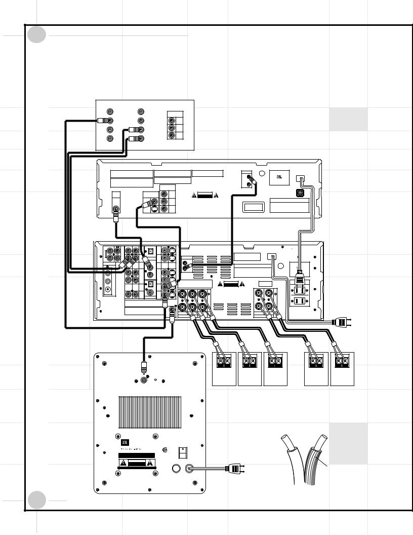
Quick Installation Diagrams
BASIC INSTALLATION: Your TV must at a minimum have a composite video input (this connector usually has a yellow-colored core), and Left (usually has a white-colored core) and Right (red-colored core) Stereo audio preamp-level
RCA outputs. All wires for this hookup are included.
S-VIDEO IN |
S-VIDEO OUT |
COMPONENT |
TV |
Yellow |
|
||
|
VIDEO IN |
|
|
|
|
|
|
VIDEO IN |
VIDEO OUT |
Pr |
|
L |
L |
Pb |
|
|
|
||
AUDIO IN |
AUDIO OUT |
Y |
|
|
|
|
|
R |
R |
|
|
White |
|
|
|
|
|
|
|
|
|
|
|
|
|
|
|
|
|
|
|
Red |
|
|
|
|
|
|
|
|
|
|
|
|
|
|
|
|
|
|
|
|
|
|
|
|
|
|
|
|
|
|
|
|
|
|
|
DVD600 |
|
Manufactured under license from Dolby Laboratories. |
Apparatus Claims of |
U.S. Patent Nos. 4,631,603, |
"DTS" and "DTS Digital Out" are trademarks |
REMOTE |
|
U® L |
|
|
|
|
|
AC INPUT |
|||||
|
"Dolby", "Pro Logic" and the double-D symbols are trademarks |
4,577,216, |
4,819,098, and |
4,907,093 licensed for |
|
|
MODEL NO. DVD 600 |
~120V/60Hz 25W |
||||||||||
|
of Dolby Laboratories. Confidential Unpublished Works. |
limited viewing uses only. |
|
of Digital Theater Systems, Inc. |
|
IN |
C |
US |
|
|||||||||
|
' 1992-1997 Dolby Laboratories, Inc. All rights reserved. |
|
|
|
|
|
|
|
LISTED |
|
|
|
|
|
|
|||
|
This device complies with part 15 of the FCC rules. Operation is |
CERTIFIFICATION - THIS PRODUCT COMPLIES WITH DHHS |
|
|
|
|
E206909 |
|
|
NORTHRIDGE |
|
|
||||||
|
|
RULES 21 CFR, SUBCHAPTER J, PART |
|
|
|
|
7H57 |
|
|
|
|
|||||||
|
subject to the following two conditions; (1) This device may not |
|
1040 AT DATE OF MANUFACTURE |
|
|
|
AUDIO/VIDEO |
CALIFORNIA, USA |
|
|||||||||
|
cause harmful interference, and (2) This device must accept any |
|
|
|
|
|
|
OUT |
EQUIPMENT |
|
|
|
|
|
||||
|
interference received, including interference that may cause |
|
|
|
|
|
|
|
|
|
|
|
|
|
|
|||
|
undesired operation. |
|
|
COMPONENT |
|
|
|
|
|
|
|
|
|
|
|
|
||
|
|
|
|
|
|
|
|
|
|
|
|
|
|
|
|
|||
|
|
|
|
|
VIDEO OUT |
|
|
|
|
|
|
|
|
|
|
|
|
|
|
DIGITAL |
|
VIDEO OUT |
|
|
Pr |
|
CAUTION |
|
|
|
|
|
|
|
|
|
1 |
|
OUT |
|
|
|
|
|
RISK OF ELECTRIC SHOCK |
|
|
|
|
|
|
|
|
|
|
|
|
|
|
|
|
|
|
DO NOT OPEN |
|
|
|
|
|
|
|
|
|
|
|
|
|
|
|
|
|
|
|
AVIS : RISQUE DE CHOC |
|
|
|
|
|
|
|
|
SERIAL NO. |
|
|
COAXIAL |
|
VIDEO |
|
|
Pb |
|
ÉLECTRIQUE–NE PAS OUVRIR |
|
|
|
|
|
|
|
|||
|
|
|
|
|
|
|
|
|
|
|
|
|
|
|||||
|
|
|
|
|
|
|
WARNING: TO REDUCE THE RISK OF FIRE OR ELECTRIC SHOCK, |
|
CLASS 1 |
|
|
|
|
|
|
|
||
|
|
|
|
|
|
|
DO NOT EXPOSE THIS APPLIANCE TO RAIN OR MOISTURE. |
|
|
|
|
|
|
|
|
|||
|
|
|
S-VIDEO |
|
|
Y |
AVERTISSEMENT: POUR PRÉVENIR LES RISQUES D'INCENDIE |
LASER PRODUCT |
|
|
|
|
|
|
||||
|
|
|
|
|
|
|
OU DE CHOC ÉLECTRIQUE, ÉVITER D'EXPOSER CET APPAREIL |
|
|
|
|
|
|
|
|
|
||
|
|
|
|
|
|
|
A LA PLUIE OU A L'HUMIDITÉ. |
|
|
|
|
|
|
|
|
|
|
|
|
|
Yellow |
|
|
|
|
|
|
Black |
|
|
|
|
|
|
|
||
|
Orange |
|
|
|
|
|
|
|
|
|
|
|
|
|
|
|
|
|
L |
R |
|
OPTICAL |
|
|
|
|
|
|
|
|
|
|
|
|
|
|
DCR600 |
VID 3 |
VID 3 |
|
|
|
|
|
|
|
|
|
AC INPUT |
|
|
|
|
|||
|
IN |
|
|
|
|
|
|
|
|
|
|
|
|
|
|
|||
|
|
|
|
|
|
|
|
|
|
|
~120V/60Hz |
A |
|
|
|
|||
|
|
IN |
|
IN |
|
|
|
|
|
|
|
|
|
|
|
|
||
|
TAPE |
|
|
|
|
|
|
|
U.S. Patent Nos. |
|
|
|
|
|
|
|
|
|
|
|
VID 2 |
|
VID 2 |
|
|
REMOTE |
|
4,893,342, |
4,910,779, |
4,975,954 |
|
|
|
|
|
|
|
|
OUT |
DIGITAL IN |
|
|
|
5,034,983, |
5,136,651, |
and 5,333,200 |
|
|
|
|
|
|
|
|||
|
|
IN |
IN |
|
|
|
|
Cooper Bauck Transaural Stereo |
|
|
|
|
|
|
|
|||
ANTENNA |
|
COAXIAL |
|
|
|
IN |
|
|
|
SERIAL NO. |
|
|
|
|
U® L |
|
MODEL NO. DCR 600 |
|
|
L |
R |
|
|
VIDEO |
S-VIDEO |
|
|
|
|
|
|
|
|
|
|||
|
1 |
|
OUT |
|
|
|
|
|
|
C |
US |
|
||||||
|
|
|
(DVD) |
|
|
|
|
|
|
|
|
|
|
|
LISTED |
|
|
|
|
|
|
|
|
|
|
|
|
|
|
|
|
|
|
|
E191351 |
|
NORTHRIDGE |
|
AM |
IN |
|
IN |
|
|
|
|
|
|
|
|
|
|
|
40KK |
|
|
|
|
VID 1 |
2 |
VID 1 |
|
|
|
|
|
|
|
|
|
|
AUDIO EQUIPMENT |
CALIFORNIA, USA |
||
|
|
|
|
|
|
|
|
|
|
|
|
|
|
|
|
|
||
|
GND |
OUT |
|
OUT |
|
|
This device complies with part 15 of the FCC rules. Operation is |
|
|
|
|
|
|
|
|
|
AC OUTLETS |
|
|
|
|
|
|
|
|
subject to the following two conditions: (1) This device may not |
CAUTION |
|
|
|
|
|
|
|
|
||
|
|
|
OPT |
|
|
cause harmful interference, and (2) This device must accept any |
RISK OF ELECTRIC SHOCK |
|
|
|
|
|
|
|
|
~120V/60Hz |
||
|
|
|
|
|
interference received, including interference that may cause |
|
|
|
|
|
|
|
|
UNSWITCHED/100W, 1A MAX |
||||
|
L |
R |
|
DVD |
|
|
undesired operation. |
|
DO NOT OPEN |
|
|
|
|
|
|
|
|
|
|
FM |
|
|
IN |
|
|
|
|
AVIS : RISQUE DE CHOC |
|
|
|
|
|
|
|
|
|
|
75Ω |
|
|
|
|
|
|
|
ÉLECTRIQUE-NE PAS OUVRIR |
|
|
|
|
|
|
|
|
|
|
|
CD |
|
MON. |
|
|
|
|
WARNING: TO REDUCE THE RISK OF FIRE OR ELECTRIC SHOCK, |
|
|
|
|
|
|
|
||
|
|
IN |
|
OUT |
|
|
|
|
DO NOT EXPOSE THIS APPLIANCE TO RAIN OR MOISTURE. |
|
|
|
|
|
|
|
SWITCHED/50W, 0.5A MAX |
|
|
|
|
|
|
|
|
AVERTISSEMENT: POUR PRÉVENIR LES RISQUES D'INCENDIE |
|
|
|
|
|
|
|||||
|
|
|
DIGITAL OUT |
|
|
|
|
|
|
|
|
|
|
|
||||
|
|
|
|
|
|
|
|
|
OU DE CHOC ÉLECTRIQUE, ÉVITER D'EXPOSER CET APPAREIL |
|
|
|
|
|
|
|
||
|
Manufactured under license from Digital Theater Systems, Inc. US Pat. |
|
|
|
|
A LA PLUIE OU A L'HUMIDITÉ. |
|
|
|
|
|
|
|
|
CONNECT TO |
|||
|
Copyright 1996 Digital Theater Systems, Inc. All Rights Reserved. |
|
|
|
|
|
|
|
|
|
|
|
|
|
||||
|
No 5,451,942 and other world-wide patents issued and pending. "DTS", |
|
|
|
|
|
|
|
|
|
|
|
|
|
|
|||
|
"DTS Digital Surround", are trademarks of Digital Theater Systems, Inc. |
|
|
|
|
|
|
|
|
|
|
|
|
|
|
|||
Manufactured under license from Dolby Laboratories. |
|
|
|
|
|
|
|
|
|
|
|
AC OUTLET |
|
"Dolby", "Pro Logic" and the double-D symbols are trademarks |
|
|
|
|
|
|
|
|
|
|
|
||
of Dolby Laboratories. Confidential Unpublished Works. |
LFE/ |
RIGHT |
LEFT |
CENTER |
|
|
RIGHT |
LEFT |
|
|
|
||
' 1992-1997 Dolby Laboratories, Inc. All rights reserved. |
|
|
|
|
|
|
|
||||||
|
SUBWOOFER |
FRONT SPKRS (8Ω ) |
SPKR (8Ω ) |
|
|
SURR. SPKRS |
(8Ω ) |
|
|
|
|
|
|
Brown |
|
|
|
|
|
|
|
|
|
|
|
|
|
|
|
|
|
Red |
White |
Green |
Yellow |
Blue |
|||||
|
|
|
|
– |
+ |
– |
+ |
– |
+ |
– |
+ |
– |
+ |
LFE |
|
|
|
|
|
|
|
|
|
|
|
|
|
|
|
|
|
RIGHT FRONT |
LEFT FRONT |
CENTER |
RIGHT SURROUND |
LEFT SURROUND |
|||||
GREEN: ON |
|
|
|
SPEAKER |
SPEAKER |
SPEAKER |
SPEAKER |
SPEAKER |
|||||
RED: STAND-BY |
|
|
|
|
|
|
|
|
|
|
|
|
|
NOTES:
1. CONNECT “RIDGED” WIRE TO (+) RED ON DCR600 AND SPEAKERS.
2. WIRE COLOR CODES ARE FOR EASE OF CONNECTION.
THE SPEAKER WIRES CAN BE INTERCHANGED IF NECESSARY.
(—) |
(+) |
SUB135S |
|
POWER |
JBL, Incorporated |
|
CONNECT TO |
|
NRTL/C |
|
This area is designed to become quite warm |
CSA 22-2 No.1 |
AC OUTLET |
during normal operation |
UL 1492 |
|
CAUTION |
|
|
RISK OF ELECTRIC SHOCK |
2.5A/250V |
Ridges |
DO NOT OPEN |
||
AVIS: RISQUE DE CHOC ELECTRIQUE-NE PAS OUVRIR |
FUSE |
|
|
|
|
|
TYPE T |
|
|
"WARNING: FOR CONTINUED |
AC 120V~60Hz |
|
PROTECTION AGAINST RISK |
|
"WARNING: TO REDUCE THE RISK OF FIRE OR ELECTRIC SHOCK, |
OR FIRE, REPLACE ONLY WITH |
200 Watts |
DO NOT EXPOSE THIS APPLIANCE TO RAIN OR MOISTURE." |
SAME TYPE 2.5A, 250 VOLT |
|
"AVERTISSEMENT: POUR PR VENIR LES RISQUES D’INCENDIE OU |
"AVERTISSEMENT: UTILISEZ UN |
|
DE CHOC LECTRIQUE, VITER D’EXPOSER CET APPAREIL A LA |
FUSIBLE DE RECHANGE DE MEME |
|
PLUIE OU A L’HUMIDIT . " |
TYPE 2.5A, 250V" |
|
6 |
SCS135S |
|
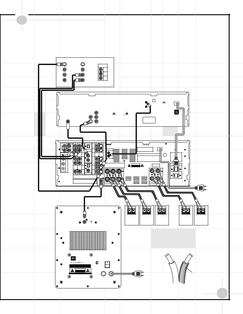
Quick Installation Diagrams (Continued)
ALTERNATE INSTALLATION FOR BETTER PICTURE QUALITY: Your TV must have an S-Video input, and Left (usually has a white-colored core) and Right (red-colored core) Stereo audio preamp-level RCA outputs. Two pieces of S-Video cable are not included and should be purchased separately.
S-Video cable not included
S-VIDEO IN |
S-VIDEO OUT |
COMPONENT |
TV |
|
|
||
|
|
VIDEO IN |
|
VIDEO IN |
VIDEO OUT |
Pr |
|
L |
L |
Pb |
|
|
|
||
AUDIO IN |
AUDIO OUT |
Y |
|
|
|
|
|
R |
R |
|
|
White
Red
DVD600
|
Manufactured under license from Dolby Laboratories. |
|
|
Apparatus Claims of U.S. Patent Nos. 4,631,603, |
|
"DTS" and "DTS Digital Out" are trademarks |
|
REMOTE |
C U® L US |
|
|
AC INPUT |
||||||||||||||
|
"Dolby", "Pro Logic" and the double-D symbols are trademarks |
4,577,216, 4,819,098, and 4,907,093 licensed for |
|
MODEL NO. DVD 600 |
|
~120V/60Hz 25W |
||||||||||||||||||||
|
|
of Digital Theater Systems, Inc. |
|
|
|
|
||||||||||||||||||||
|
of Dolby Laboratories. Confidential Unpublished Works. |
limited viewing uses only. |
|
|
|
|
|
|
|
|
||||||||||||||||
|
' 1992-1997 Dolby Laboratories, Inc. All rights reserved. |
|
|
|
|
|
|
|
|
|
|
IN |
|
LISTED |
|
|
|
|
||||||||
|
|
|
|
|
|
|
|
|
|
|
|
|
|
|
|
|
|
|
|
|
|
|
|
|
||
|
This device complies with part 15 of the FCC rules. Operation is |
CERTIFIFICATION - THIS PRODUCT COMPLIES WITH DHHS |
|
|
|
|
|
|
|
E206909 |
NORTHRIDGE |
|
|
|
||||||||||||
|
subject to the following two conditions; (1) This device may not |
|
RULES 21 CFR, SUBCHAPTER J, PART |
|
|
|
|
|
|
|
|
7H57 |
|
|
|
|||||||||||
|
|
1040 AT DATE OF MANUFACTURE |
|
|
|
|
|
|
|
|
AUDIO/VIDEO |
CALIFORNIA, USA |
|
|
|
|||||||||||
|
cause harmful interference, and (2) This device must accept any |
|
|
|
|
|
|
|
|
|
|
OUT |
|
EQUIPMENT |
|
|
|
|
||||||||
|
interference received, including interference that may cause |
|
|
|
|
|
|
|
|
|
|
|
|
|
|
|||||||||||
|
undesired operation. |
|
|
|
COMPONENT |
|
|
|
|
|
|
|
|
|
|
|
|
|
|
|
||||||
|
|
|
|
|
|
|
|
|
|
VIDEO OUT |
|
|
|
|
|
|
|
|
|
|
|
|
|
|
|
|
|
|
DIGITAL |
|
|
VIDEO OUT |
|
|
Pr |
|
|
|
|
CAUTION |
|
|
|
|
|
|
|
|
|
|
|||
|
|
|
OUT |
|
|
|
|
|
|
|
|
|
RISK OF ELECTRIC SHOCK |
|
|
|
|
|
|
|
|
|
|
|||
|
|
|
|
|
|
|
|
|
|
|
|
|
|
DO NOT OPEN |
|
|
|
|
|
|
|
|
|
|
||
|
|
|
|
|
|
|
|
|
|
|
|
|
|
|
AVIS : RISQUE DE CHOC |
|
|
|
|
|
SERIAL NO. |
|
||||
|
|
COAXIAL |
|
|
VIDEO |
|
|
|
Pb |
|
|
|
ÉLECTRIQUE–NE PAS OUVRIR |
|
|
|
|
|
|
|||||||
|
|
|
|
|
|
|
|
WARNING: TO REDUCE THE RISK OF FIRE OR ELECTRIC SHOCK, |
|
|
|
|
|
|
|
|
||||||||||
|
|
|
|
|
|
|
|
|
|
|
|
|
|
DO NOT EXPOSE THIS APPLIANCE TO RAIN OR MOISTURE. |
|
CLASS 1 |
|
|
|
|
|
|||||
|
|
|
|
|
|
|
|
|
|
|
Y |
|
AVERTISSEMENT: POUR PRÉVENIR LES RISQUES D'INCENDIE |
|
LASER PRODUCT |
|
|
|
|
|
||||||
|
|
|
|
|
|
|
|
|
|
|
|
|
OU DE CHOC ÉLECTRIQUE, ÉVITER D'EXPOSER CET APPAREIL |
|
|
|
|
|
|
|
|
|||||
|
|
|
|
|
|
|
|
|
|
|
|
|
|
A LA PLUIE OU A L'HUMIDITÉ. |
|
|
|
|
|
|
|
|
||||
|
|
|
|
|
|
|
|
|
|
|
|
|
|
|
|
|
|
|
|
|
|
|
|
|
|
|
|
|
|
|
|
|
Black |
|
|
|
Orange S-Video cable not included |
|
|
|
|
|||
L |
R |
OPTICAL |
|
|
|
|
|
DCR600 |
|
|
|
|
AC INPUT |
|
|||
|
IN |
VID 3 |
VID 3 |
|
|
|
|
|
|
|
|
|
~120V/60Hz |
A |
|||
|
|
IN |
IN |
|
|
|
||
|
TAPE |
|
|
|
U.S. Patent Nos. |
|
|
|
|
|
|
VID 2 |
REMOTE |
4,893,342, |
4,910,779, |
4,975,954 |
|
|
|
IN |
5,034,983, |
5,136,651, |
and 5,333,200 |
|
||
|
|
IN |
|
Cooper Bauck Transaural Stereo |
|
|||
ANTENNA |
|
|
|
IN |
|
|
|
|
|
|
VIDEO |
S-VIDEO |
|
|
SERIAL NO. |
|
|
|
|
1 |
|
|
|
|||
|
|
|
OUT |
|
|
|
|
|
|
|
(DVD) |
|
|
|
|
|
|
AM |
|
IN |
IN |
|
|
|
|
|
|
|
2 |
VID 1 |
|
|
|
|
|
|
|
VID 1 |
|
|
|
|
|
|
GND |
|
OUT |
OUT |
device complies with part 15 of the FCC rules. Operation is |
|
|
|
|
|
|
|
|
to the following two conditions: (1) This device may not |
CAUTION |
|
|
|
|
|
OPT |
|
harmful interference, and (2) This device must accept any |
RISK OF ELECTRIC SHOCK |
|
|
|
|
|
|
DVD |
interference received, including interference that may cause |
DO NOT OPEN |
|
|
|
|
L |
R |
operation. |
AVIS : RISQUE DE CHOC |
|
|
|
|
FM |
|
|
IN |
|
|
|
|
|
75Ω |
|
|
|
|
ÉLECTRIQUE-NE PAS OUVRIR |
|
|
|
|
|
CD |
MON. |
|
WARNING: TO REDUCE THE RISK OF FIRE OR ELECTRIC SHOCK, |
|
||
|
|
IN |
OUT |
|
DO NOT EXPOSE THIS APPLIANCE TO RAIN OR MOISTURE. |
|
|
|
|
|
DIGITAL OUT |
|
|
AVERTISSEMENT: POUR PRÉVENIR LES RISQUES D'INCENDIE |
|
||
|
|
|
|
|
OU DE CHOC ÉLECTRIQUE, ÉVITER D'EXPOSER CET APPAREIL |
|
||
|
Manufactured under license from Digital Theater Systems, Inc. US Pat. |
|
A LA PLUIE OU A L'HUMIDITÉ. |
|
|
CONNECT TO |
||
|
Copyright 1996 Digital Theater Systems, Inc. All Rights Reserved. |
|
|
|
|
|||
|
No 5,451,942 and other world-wide patents issued and pending. "DTS", |
|
|
|
|
|
||
|
"DTS Digital Surround", are trademarks of Digital Theater Systems, Inc. |
|
|
|
|
|
||
Manufactured under license from Dolby Laboratories. |
|
|
AC OUTLET |
"Dolby", "Pro Logic" and the double-D symbols are trademarks |
|
|
|
of Dolby Laboratories. Confidential Unpublished Works. |
|
|
|
' 1992-1997 Dolby Laboratories, Inc. All rights reserved. |
LFE/ |
RIGHT |
RIGHT |
|
FRONT |
SURR. |
|
|
|
Brown |
|
|
|
|
|
|
Red |
White |
Green |
Yellow |
Blue |
|
RIGHT FRONT |
LEFT FRONT |
CENTER |
RIGHT SURROUND |
LEFT SURROUND |
GREEN: ON |
SPEAKER |
SPEAKER |
SPEAKER |
SPEAKER |
SPEAKER |
RED: STAND-BY |
|
|
|
|
|
NOTES:
1. CONNECT “RIDGED” WIRE TO (+) RED ON DCR600 AND SPEAKERS.
2. WIRE COLOR CODES ARE FOR EASE OF CONNECTION.
THE SPEAKER WIRES CAN BE INTERCHANGED IF NECESSARY.
(—) |
(+) |
SUB135S |
|
POWER |
|
JBL, Incorporated |
|
CONNECT TO |
|
|
NRTL/C |
||
This area is designed to become quite warm |
AC OUTLET |
||
CSA 22-2 No.1 |
|||
during normal operation |
UL 1492 |
||
CAUTION |
|
|
|
RISK OF ELECTRIC SHOCK |
2.5A/250V |
Ridges |
|
DO NOT OPEN |
|||
AVIS: RISQUE DE CHOC ELECTRIQUE-NE PAS OUVRIR |
FUSE |
|
|
|
|
||
|
TYPE T |
|
|
"WARNING: FOR CONTINUED |
AC 120V~60Hz |
|
PROTECTION AGAINST RISK |
|
"WARNING: TO REDUCE THE RISK OF FIRE OR ELECTRIC SHOCK, |
OR FIRE, REPLACE ONLY WITH |
200 Watts |
DO NOT EXPOSE THIS APPLIANCE TO RAIN OR MOISTURE." |
SAME TYPE 2.5A, 250 VOLT |
|
"AVERTISSEMENT: POUR PR VENIR LES RISQUES D’INCENDIE OU |
"AVERTISSEMENT: UTILISEZ UN |
|
DE CHOC LECTRIQUE, VITER D’EXPOSER CET APPAREIL A LA |
FUSIBLE DE RECHANGE DE MEME |
|
PLUIE OU A L’HUMIDIT . " |
TYPE 2.5A, 250V" |
|
SCS135S |
7 |
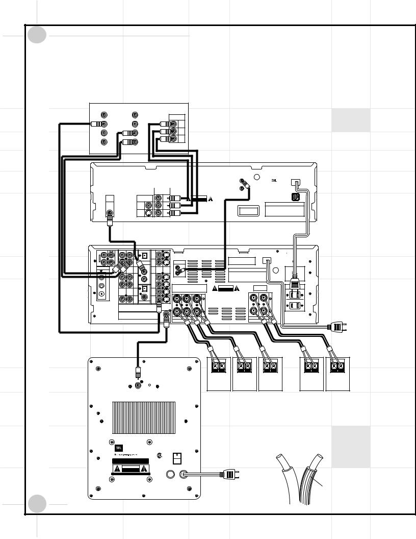
Quick Installation Diagrams (Continued)
ALTERNATE INSTALLATION FOR BEST PICTURE QUALITY: Your TV must have Y/Pr/Pb component video inputs (three separate RCA connectors with red-, blueand green-colored cores), and Left (usually has a white-colored core) and Right (red-colored core) Stereo audio preamp-level RCA outputs. The composite video cable is not included and should be purchased separately. This setup requires that the TV s own video switching is utilized to access DVD picture. All other video switching is still done through the DCR600.
S-VIDEO IN |
S-VIDEO OUT |
COMPONENT |
TV |
Yellow |
|
VIDEO IN |
|
|
|
|
|
VIDEO IN |
VIDEO OUT |
Pr |
|
L |
L |
Pb |
|
|
|
||
AUDIO IN |
AUDIO OUT |
Y |
|
|
|
|
|
R |
R |
|
|
White |
|
|
|
|
Red |
|
|
DVD600
Manufactured under license from Dolby Laboratories. |
Apparatus Claims of U.S. Patent Nos. 4,631,603, |
"DTS" and "DTS Digital Out" are trademarks |
|
REMOTE |
|
U® L US |
|
AC INPUT |
||
"Dolby", "Pro Logic" and the double-D symbols are trademarks |
4,577,216, 4,819,098, and 4,907,093 licensed for |
|
|
MODEL NO. DVD 600 |
~120V/60Hz 25W |
|||||
of Dolby Laboratories. Confidential Unpublished Works. |
limited viewing uses only. |
of Digital Theater Systems, Inc. |
|
|
C |
|
||||
' 1992-1997 Dolby Laboratories, Inc. All rights reserved. |
|
|
|
|
|
IN |
|
LISTED |
|
|
|
|
|
|
|
|
|
|
|
||
This device complies with part 15 of the FCC rules. Operation is |
CERTIFIFICATION - THIS PRODUCT COMPLIES WITH DHHS |
|
|
|
|
E206909 |
NORTHRIDGE |
|
||
subject to the following two conditions; (1) This device may not |
|
RULES 21 CFR, SUBCHAPTER J, PART |
|
|
|
|
7H57 |
|
||
|
1040 AT DATE OF MANUFACTURE |
|
|
|
AUDIO/VIDEO |
CALIFORNIA, USA |
|
|||
cause harmful interference, and (2) This device must accept any |
|
|
|
|
|
|
EQUIPMENT |
|
|
|
interference received, including interference that may cause |
|
|
|
|
OUT |
|
|
|||
undesired operation. |
|
COMPONENT |
|
|
|
|
|
|
|
|
|
|
VIDEO OUT |
|
|
|
|
|
|
|
|
|
DIGITAL |
VIDEO OUT |
|
Pr |
CAUTION |
|
|
|
|
|
OUT |
|
|
RISK OF ELECTRIC SHOCK |
|
|
|
|
|
|
|
|
|
DO NOT OPEN |
|
|
|
|
|
|
|
|
|
|
AVIS : RISQUE DE CHOC |
|
|
|
SERIAL NO. |
|
COAXIAL |
VIDEO |
|
Pb |
ÉLECTRIQUE–NE PAS OUVRIR |
|
|
||
|
|
|
|
|
|||||
|
|
|
|
|
WARNING: TO REDUCE THE RISK OF FIRE OR ELECTRIC SHOCK, |
|
CLASS 1 |
|
|
|
|
|
|
|
DO NOT EXPOSE THIS APPLIANCE TO RAIN OR MOISTURE. |
|
|
||
|
|
S-VIDEO |
|
Y |
AVERTISSEMENT: POUR PRÉVENIR LES RISQUES D'INCENDIE |
LASER PRODUCT |
|
||
|
|
|
OU DE CHOC ÉLECTRIQUE, ÉVITER D'EXPOSER CET APPAREIL |
|
|
|
|||
|
|
|
|
|
|
|
|
||
|
|
|
|
|
A LA PLUIE OU A L'HUMIDITÉ. |
|
|
|
|
|
|
|
|
|
|
|
Black |
|
|
|
Orange |
|
|
|
|
|
|
|
|
L |
R |
OPTICAL |
|
|
|
|
|
|
DCR600 |
|
|
|
|
|
AC INPUT |
|
|||
|
IN |
VID 3 |
VID 3 |
|
|
|
|
|
|
|
|
|
|
|
~120V/60Hz |
A |
|||
|
|
IN |
IN |
|
|
|
|
||
|
TAPE |
|
|
|
|
U.S. Patent Nos. |
|
|
|
|
|
|
VID 2 |
|
REMOTE |
4,893,342, |
4,910,779, |
4,975,954 |
|
|
|
IN |
|
5,034,983, |
5,136,651, |
and 5,333,200 |
|
||
|
|
IN |
|
|
Cooper Bauck Transaural Stereo |
|
|||
ANTENNA |
|
VIDEO |
S-VIDEO |
IN |
|
|
SERIAL NO. |
|
|
|
|
1 |
|
|
|
|
|||
|
|
|
|
OUT |
|
|
|
|
|
|
|
(DVD) |
|
|
|
|
|
|
|
|
|
|
|
|
|
|
|
|
|
|
AM |
IN |
IN |
|
|
|
|
|
|
|
|
2 |
VID 1 |
|
|
|
|
|
|
|
|
VID 1 |
|
|
|
|
|
|
|
|
GND |
OUT |
OUT |
|
This device complies with part 15 of the FCC rules. Operation is |
|
|
|
|
|
|
|
|
|
subject to the following two conditions: (1) This device may not |
CAUTION |
|
|
|
|
|
OPT |
|
|
cause harmful interference, and (2) This device must accept any |
RISK OF ELECTRIC SHOCK |
|
|
|
|
|
|
DVD |
|
interference received, including interference that may cause |
DO NOT OPEN |
|
|
|
|
L |
R |
|
undesired operation. |
AVIS : RISQUE DE CHOC |
|
|
|
|
|
FM |
|
IN |
|
|
|
|
|
|
|
75Ω |
|
|
|
|
ÉLECTRIQUE-NE PAS OUVRIR |
|
|
|
|
|
CD |
MON. |
|
|
WARNING: TO REDUCE THE RISK OF FIRE OR ELECTRIC SHOCK, |
|
||
|
|
IN |
OUT |
|
|
DO NOT EXPOSE THIS APPLIANCE TO RAIN OR MOISTURE. |
|
|
|
|
|
DIGITAL OUT |
|
|
|
AVERTISSEMENT: POUR PRÉVENIR LES RISQUES D'INCENDIE |
|
||
|
|
|
|
|
|
OU DE CHOC ÉLECTRIQUE, ÉVITER D'EXPOSER CET APPAREIL |
|
||
|
Manufactured under license from Digital Theater Systems, Inc. US |
|
|
A LA PLUIE OU A L'HUMIDITÉ. |
|
|
CONNECT TO |
||
|
Copyright 1996 Digital Theater Systems, Inc. All Rights Reserved. |
|
|
|
|
|
|||
|
No 5,451,942 and other world-wide patents issued and pending. "DTS", |
|
|
|
|
|
|
||
|
"DTS Digital Surround", are trademarks of Digital Theater Systems, |
|
|
|
|
|
|
||
Manufactured under license from Dolby Laboratories. |
|
|
AC OUTLET |
"Dolby", "Pro Logic" and the double-D symbols are trademarks |
|
|
|
of Dolby Laboratories. Confidential Unpublished Works. |
|
|
|
' 1992-1997 Dolby Laboratories, Inc. All rights reserved. |
LFE/ |
RIGHT |
RIGHT |
|
FRONT |
SURR. |
|
|
|
Brown |
|
|
|
|
|
|
Red |
White |
Green |
Yellow |
Blue |
|
RIGHT FRONT |
LEFT FRONT |
CENTER |
RIGHT SURROUND |
LEFT SURROUND |
GREEN: ON |
SPEAKER |
SPEAKER |
SPEAKER |
SPEAKER |
SPEAKER |
RED: STAND-BY |
|
|
|
|
|
NOTES:
1. CONNECT “RIDGED” WIRE TO (+) RED ON DCR600 AND SPEAKERS.
2. WIRE COLOR CODES ARE FOR EASE OF CONNECTION.
THE SPEAKER WIRES CAN BE INTERCHANGED IF NECESSARY. 3. MUST USE VIDEO SWITCHING THROUGH TV TO ACCESS COMPONENT VIDEO.
SUB135S |
|
POWER |
|
(—) |
(+) |
JBL, Incorporated |
|
|
CONNECT TO |
||
|
NRTL/C |
|
|
|
|
This area is designed to become quite warm |
|
AC OUTLET |
|
|
|
CSA 22-2 No.1 |
|
|
|
||
during normal operation |
UL 1492 |
|
|
|
|
CAUTION |
|
|
|
|
|
RISK OF ELECTRIC SHOCK |
|
|
|
|
|
DO NOT OPEN |
|
|
|
|
|
AVIS: RISQUE DE CHOC ELECTRIQUE-NE PAS OUVRIR |
FUSE |
|
|
|
|
2.5A/250V |
|
|
|
|
|
|
TYPE T |
|
|
|
|
|
"WARNING: FOR CONTINUED |
AC 120V~60Hz |
|
|
|
|
PROTECTION AGAINST RISK |
|
|
Ridges |
|
"WARNING: TO REDUCE THE RISK OF FIRE OR ELECTRIC SHOCK, |
OR FIRE, REPLACE ONLY WITH |
200 Watts |
|
|
|
DO NOT EXPOSE THIS APPLIANCE TO RAIN OR MOISTURE." |
SAME TYPE 2.5A, 250 VOLT |
|
|
||
DE CHOC LECTRIQUE, VITER D’EXPOSER CET APPAREIL A LA |
FUSIBLE DE RECHANGE DE MEME |
|
|
|
|
"AVERTISSEMENT: POUR PR VENIR LES RISQUES D’INCENDIE OU |
"AVERTISSEMENT: UTILISEZ UN |
|
|
|
|
PLUIE OU A L’HUMIDIT . " |
TYPE 2.5A, 250V" |
|
|
|
|
8
SCS135S
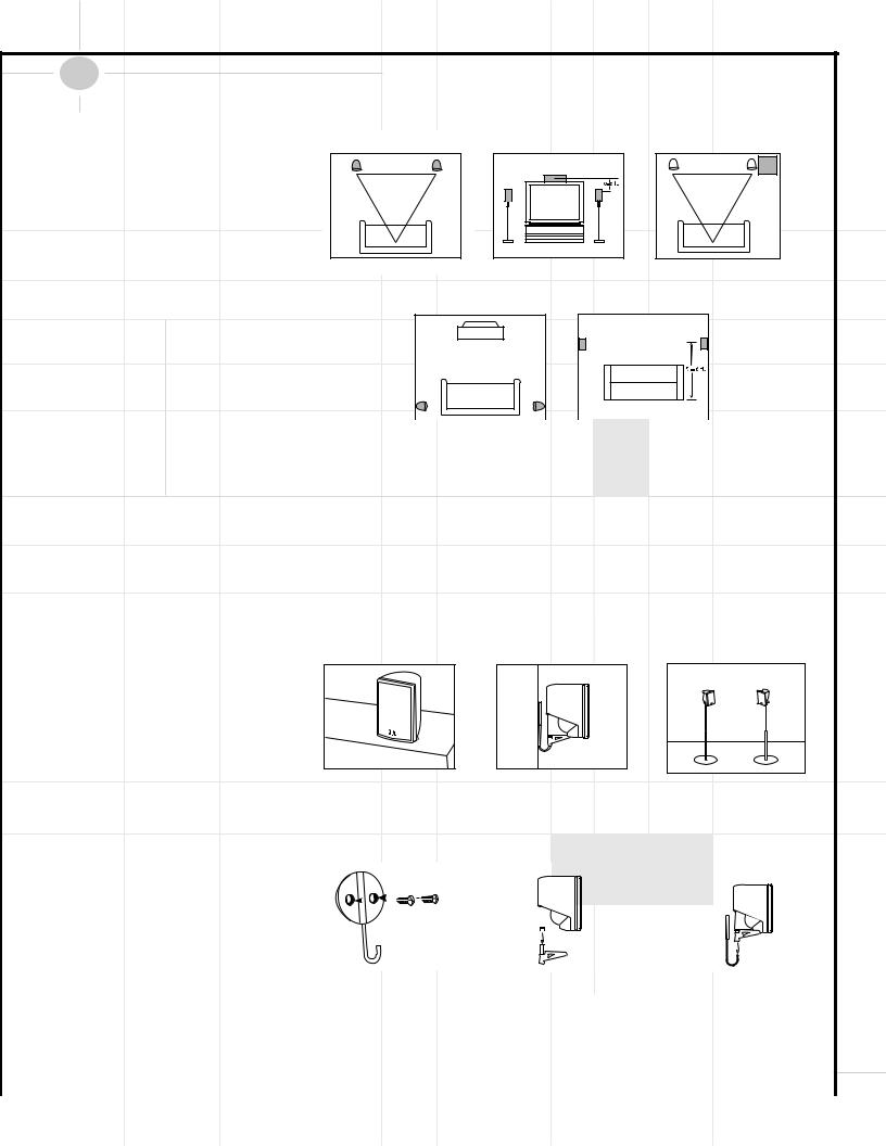
Where to Place the Speakers |
|
||
The front speakers should be placed the same |
Front Speakers |
Center-Channel Speaker |
Subwoofer |
distance from each other as they are from the |
|
|
|
listening position. They should be placed at |
|
|
|
about the same height from the floor as the |
|
|
|
listeners’ ears will be, or they may be angled |
|
|
|
toward the listeners. |
|
|
|
The center-channel speaker should be placed |
|
|
|
slightly behind the front left and right speakers, |
|
|
|
and no more than two feet above or below the |
|
|
|
tweeters of the left and right speakers. It is |
|
Surround Speakers |
|
often convenient to set the center speaker on |
|
|
|
top of the television set, as shown in the drawing. |
|
|
|
Use the supplied support leg to aim it toward |
|
|
|
the listener by screwing the leg in to angle the |
|
|
|
speaker up, or unscrewing the leg slightly to |
|
|
|
angle the speaker down. |
|
|
|
The two surround speakers should be placed |
|
|
|
|
|
|
|
|
|
|
|
|
|
|
|
slightly behind the listening position and, ideally, |
|
|
|
|
|
|
|
should face each other and be at a level higher |
The low-frequency material reproduced by the |
in the listening |
position and moving around the |
||||
than the listeners’ ears. If that is not possible, |
subwoofer is mostly omnidirectional, and this |
room until the |
bass reproduction is best. Place |
||||
they may be placed on a wall behind the listening |
speaker may be placed in a convenient location |
the subwoofer |
in that location. |
||||
position, facing forward. The surround speakers |
in the room. However, the best reproduction of |
|
|
|
|
||
should not call attention to themselves. |
bass will be heard when the subwoofer is |
|
|
|
|
||
Experiment with their placement until you hear a |
placed in a corner along the same wall as the |
|
|
|
|
||
diffuse, ambient sound accompanying the main- |
front speakers. Experiment with subwoofer |
|
|
|
|
||
program material heard in the front speakers. |
placement by temporarily placing the subwoofer |
|
|
|
|
||
Mounting Options
Satellites and Surrounds
On shelves. |
On the wall. Wall brackets |
On optional stands (FS300). |
|
are included. |
|
Wall-Mounting
|
|
|
|
|
|
|
|
|
|
|
|
|
|
|
|
|
|
|
|
|
|
|
|
|
|
|
|
|
|
|
|
|
|
|
|
|
|
|
|
|
|
|
|
|
|
|
|
|
|
|
|
|
|
|
|
|
|
|
|
|
|
|
|
|
|
|
|
|
|
|
|
|
|
|
|
|
|
|
|
|
|
|
|
|
|
|
|
|
|
|
|
|
|
|
|
|
|
|
|
|
|
|
|
|
|
|
|
|
|
|
|
|
|
|
|
|
|
|
|
|
|
|
|
|
|
|
|
|
|
|
|
|
|
|
|
|
|
|
|
|
|
|
|
|
|
|
|
|
|
|
|
|
|
|
|
|
|
|
|
|
|
|
|
|
|
|
|
|
|
|
|
|
|
|
|
Attach plate |
|
to wall. The |
|
|
Slide speaker onto support. |
|
Place speaker and sup- |
||||||||||||||||
The customer is responsible for proper |
brackets should be placed, if |
|
|
|
|
|
|
port on wall plate. |
||||||||||||||||
possible, so that the screws |
|
|
|
|
|
|
|
|
|
|
|
|
|
|
|
|
||||||||
selection and use of mounting hardware, |
|
|
|
|
|
|
|
|
|
|
|
|
|
|
|
|
||||||||
|
|
|
|
|
|
|
|
|
|
|
|
|
|
|
|
|||||||||
will fasten into a wooden wall |
|
|
|
|
|
|
|
|
|
|
|
|
|
|
|
|
||||||||
available through hardware stores, to prop- |
|
|
|
|
|
|
|
|
|
|
|
|
|
|
|
|
||||||||
stud. If that is not possible, use |
|
|
|
|
|
|
|
|
|
|
|
|
|
|
|
|
||||||||
erly and safely wall-mount the speakers. |
|
|
|
|
|
|
|
|
|
|
|
|
|
|
|
|
||||||||
|
properly selected wall anchors. |
|
|
|
|
|
|
|
|
|
|
9 |
|
|
|
|||||||||
|
|
|
|
|
|
|
|
|
|
|
|
|
|
|
|
|
|
|
|
|
|
|
|
|
|
|
|
|
|
|
|
|
|
|
|
|
|
|
|
|
|
|
|
|
|
|
|
|
|
|
|
|
|
|
|
|
|
|
|
|
|
|
|
|
|
|
|
|
Connecting the Speakers |
|
|||
|
|
|
Separate and strip |
Left Front: White Wire |
Finally, connect one end of the single-lead RCA |
||
|
|
|
|||||
|
|
|
the ends of the |
Center: Green Wire |
cable with brown connectors to the LFE/Subwoofer |
||
|
|
|
speaker wire as |
output ⁄ on the back of the DCR600 receiver, |
|||
|
|
|
Right Front: Red Wire |
||||
|
|
|
shown. Speakers |
and the other end to the LFE Input 1 on the |
|||
|
|
|
and electronics ter- |
Right Rear: Yellow Wire |
back of the SCS135S subwoofer. |
||
|
|
|
minals have |
|
|
|
|
|
|
|
Left Rear: Blue Wire |
|
|
|
|
|
|
|
corresponding (+) |
|
|
|
|
|
|
|
|
|
|
|
|
|
|
|
and (–) terminals. |
|
|
|
|
|
|
|
|
|
|
||
|
Most manufacturers of speakers and electronics, |
Colors shown in parentheses are wiring color codes. |
|
|
|
||
|
including JBL, use red to denote the (+) terminal |
|
|
|
|||
|
|
|
|
|
|||
|
and |
black for the (–) terminal. |
|
|
|
|
|
|
|
|
|
|
|||
|
The (+) lead of the speaker wire is noted with a |
|
|
|
|
||
|
|
|
|
|
|||
|
|
. |
|
|
|||
|
stripe. It is important to connect both speakers |
|
|
|
|||
|
|
|
|
|
|||
|
identically: (+) on the speaker to (+) on the |
|
|
|
|
||
|
receiver and (–) on the speaker to (–) on the |
. |
|
|
|
||
|
receiver. Wiring “out of phase” results in thin |
|
|
|
|||
|
|
|
|
|
|||
|
sound, weak bass and a poor stereo image. |
|
|
|
|
||
With the advent of multichannel surround-sound systems, connecting all of the speakers in your system with the correct polarity remains equally important in order to preserve the proper ambience and directionality of the program material.
The wires for the three front speakers should all be of the same length even if the speakers will be placed at varying distances from the DCR600. The same applies to the two rear speakers. To make sure that you use the correct wires for each speaker, we have color-coded them, as shown in the diagram:
Making the Audio Connections |
|||
|
2. Connect the supplied 75-ohm FM antenna to |
4. In order to obtain the best possible sound |
|
|
the FM terminal § on the back of the DCR600. |
reproduction when watching your television, con- |
|
|
Note that if you use an optional external FM |
nect the left and right analog audio outputs of |
|
|
antenna with 300-ohm twin-lead cable, you |
your TV to the Video 2 Audio inputs h on the |
|
|
must use a 300-ohm-to-75-ohm adaptor (not |
DCR600 using the red (right) and white (left) |
|
|
supplied) to make the connection. |
leads of the supplied triple-lead RCA cable. |
|
1. Assemble the supplied AM Loop Antenna as |
3. Connect one end of the supplied single-lead |
|
|
shown above. Connect it to the AM and GND |
coaxial digital cable with orange connectors to |
|
|
terminals ¢ on the back of the DCR600. |
the COAX1 (upper) digital input gon the receiver, |
|
|
|
and connect the other end to the coaxial digital |
|
|
|
output |
on the DVD changer. |
|
10
|
|
|
|
|
|
|
|
|
|
|
|
|
|
|
|
|
|
|
|
Making the Video Connections |
|||||||||
|
|
IMPORTANT NOTE: The DCR600 and DVD600 |
nectors to the Video Monitor composite video |
If you will not be connecting additional equip- |
||||||||||
|
|
offer both S-Video and composite video inputs |
output ‚ on the receiver, and the other end to |
ment to your system just yet, you may plug in |
||||||||||
|
|
and outputs. However, you must choose one |
the composite video input jack on your television. |
the receiver, DVD changer and subwoofer. The |
||||||||||
|
|
type of connection or the other for all connec- |
This jack is often color-coded yellow; however, if |
DVD600 may be plugged into the Unswitched |
||||||||||
|
|
tions in your system. This will depend on the |
you have any questions about which jack to use, |
Accessory Outlet fl on the rear of the |
||||||||||
|
|
type of connections on your television. If both |
consult your television’s owner’s manual or your |
receiver. The receiver has a master power |
||||||||||
|
|
types of connections are available, we recom- |
dealer for assistance. |
|
|
switch 1which must be pressed in first, and a |
||||||||
|
|
mend that you purchase S-Video cables and |
OR |
|
|
|
|
|
power switch 2, which should be pressed sec- |
|||||
|
|
make those connections for superior picture |
|
|
|
|
|
ond. The last source selection will appear in the |
||||||
|
|
Connect one end of a second S-Video cable |
||||||||||||
|
|
quality. The composite video connections will |
receiver’s information display. |
|||||||||||
|
|
(not supplied) to the Video Monitor S-Video |
||||||||||||
|
|
also provide excellent results. However, the |
|
|
|
|||||||||
|
|
output ‚ on the receiver, and the other end |
The DCR600 is set at the factory to a default |
|||||||||||
|
|
DCR600 will not convert from one type of signal |
||||||||||||
|
|
to the other. |
|
to the S-Video input jack on your television. |
configuration for use with small satellite speak- |
|||||||||
|
|
1. Connect one end of the single-lead RCA cable |
3. If your television is equipped with component |
ers and a powered subwoofer such as the JBL |
||||||||||
|
|
SCS135S. If other speakers are used, then the |
||||||||||||
|
|
video (Y/Pr/Pb) inputs, in addition to the above |
||||||||||||
|
|
with yellow connectors to the composite video |
speaker configurations may need to be changed. |
|||||||||||
|
|
connections, you may use a triple-lead compo- |
||||||||||||
|
|
output |
on the DVD600 and the other end |
|
|
|
||||||||
|
|
nent video cable (not supplied) to connect the |
Although the DCR600 is set to the correct speaker |
|||||||||||
|
|
to the DVD composite video input ª on the |
||||||||||||
|
|
receiver. |
|
|
component video outputs |
on the DVD600 to |
configuration settings for the speakers supplied |
|||||||
|
|
OR |
|
|
the inputs on your television. |
|
|
with this system at the factory, you will need |
||||||
|
|
|
|
4. Connect one end of the black 1/8" mini phone |
to adjust the output levels of the speakers to |
|||||||||
|
|
Connect one end of an S-Video cable (not sup- |
customize the system to your speaker placement |
|||||||||||
|
|
plied) to the S-Video output |
on the DVD600 |
cord to the Remote IR Output ° on the |
and room acoustics. |
|||||||||
|
|
to the DVD S-Video input ª on the receiver. |
DCR600, and the other end to the Remote IR |
|
|
|
||||||||
|
|
|
|
|
|
Input |
on the DVD600. |
|
|
|
|
|
||
|
|
2. Connect one of the yellow ends of the triple- |
|
|
|
|
|
|
|
|
|
|||
|
|
lead RCA cable with red, white and yellow con- |
|
|
|
|
|
|
|
|
|
|||
|
Completing Setup |
|
|
|
|
Connect all components as per the Quick Setup |
The Power Indicator 3will turn green to |
4. If any other speaker sounds too loud or soft |
|||
Guide, or as per pages 6 thru 8 of this manual. |
confirm that the unit is on, and the |
in comparison to the front left speaker, adjust |
|||
Remove the protective plastic films from the |
Information Display Úwill also light up. |
its output level by pressing the ⁄/¤ Buttons |
|||
|
y |
on the remote, or the Selector |
|||
front panel displays of the DCR600 and DVD600. |
Setting the output levels correctly is the key to |
Buttons 5on the receiver’s front panel. |
|||
1. Plug the Power Cord ‡ into an unswitched |
preserving the enveloping surround sensation |
This will cause the test tone to pause at that |
|||
that the artists of your favorite movies intended |
speaker to allow you to make the adjustment. |
||||
AC outlet. |
|||||
for you to experience. |
When you are satisfied with the level of that |
||||
|
|||||
2. Press the Main Power Switch 1in so that |
1. Make sure the Balance Control * is in |
speaker, press the Set Button Ô |
to |
||
store the setting. The tone will continue to |
|||||
it latches in and is flush with the front panel. |
|||||
the “12 o‘clock” position, and put the DCR600 |
|||||
circulate after about 15 seconds. |
|
||||
Note that the Power Indicator 3will turn |
|
||||
amber, indicating that the unit is in the |
in Dolby Pro Logic* mode by pressing the |
5. If you are using a sound pressure level (SPL) |
|||
Surround Mode Selector t7repeat- |
|||||
Standby mode. |
|||||
edly until PRO LOGIC appears in the |
meter for precise level adjustment, start by |
||||
|
|||||
|
setting the volume so that the meter reads |
||||
3. Install the three supplied AAA batteries in the |
Main Information Display W, and the |
||||
75dB, C-Weighting, Slow. |
|
||||
remote as shown. Be certain to follow the (+) |
PRO LOGIC indicator Flights. |
|
|||
|
|
|
|||
and (–) polarity indicators that are on the bot- |
2. Press the Test Button qto start a test |
6. When you are finished adjusting the levels |
|||
tom of the battery compartment. |
for all speakers (except the subwoofer, which |
||||
tone circulating from speaker to speaker, |
|||||
|
is not adjustable using this procedure), press |
||||
|
starting with the front left speaker (indicated |
||||
|
the Test Button qto end the test tone. |
||||
|
by FL in the display), and going around |
||||
|
|
|
|
||
|
clockwise. Let it circulate once to check that |
For most installations, your DCR600 receiver |
|||
|
your speakers have been connected correctly. |
||||
|
should now be ready for use. If you would like |
||||
|
|
||||
|
is to obtain the same output level |
further information on making other, advanced |
|||
|
settings, please see the section titled |
|
|||
|
each speaker. Use the front left speaker |
|
|||
|
“Configuring the DCR600 Receiver”. |
|
|||
4. Turn the DCR600 on, either by pressing the |
as your reference, adjusting the Volume |
|
|||
|
|
|
|||
System Power Control 2on the front |
Control Óswuntil the sound coming |
|
|
|
|
panel, or by pressing an Input Selector |
from the front left speaker is at a comfortable |
|
|
11 |
|
ijklmnoon the remote. |
level. |
|
|
|
|
Quick Setup Guide to Using the JBL Cinema ProPack 600
|
The DVD600 can play discs in the following |
the Set Button |
to select this choice. You |
You can also program play lists of selected |
|
||||||||||||||||||||||||
|
formats: |
|
|
|
|
|
|
|
|
|
do not need to reset the audio output for other |
tracks or chapters. |
|
|
|
|
|||||||||||||
|
• Both 5-inch (12cm) and 3-inch (8cm) discs |
formats. The DCR600 and DVD600 will automat- |
1. Select the DVD600 by pressing the DVD |
|
|||||||||||||||||||||||||
|
• CD audio discs |
|
|
• DTS audio discs |
ically process PCM, Dolby Digital and DTS sig- |
|
|||||||||||||||||||||||
|
|
|
Button d, and press the Program Button |
||||||||||||||||||||||||||
|
|
|
nals correctly. Press the Menu Button zto |
||||||||||||||||||||||||||
|
• CD-RW audio discs |
• DVD movie discs |
46 to bring up the Program Edit Screen. |
||||||||||||||||||||||||||
|
exit the menu screen. If you press the Menu |
||||||||||||||||||||||||||||
|
• VCD video compact discs |
Button zwhile the disc is playing, you can |
2. Use the ⁄/ ¤ y |
keys to select a disc |
|||||||||||||||||||||||||
|
|
|
|
|
|
|
|
|
|
|
|
|
|
access the disc’s menu to choose the DTS for- |
|||||||||||||||
|
However, it cannot play: |
number, and press either Set |
or › |
|
|||||||||||||||||||||||||
|
mat there as well. |
|
|
|
|
||||||||||||||||||||||||
|
|
|
|
to enter the selection and move to the next |
|||||||||||||||||||||||||
|
• DVD discs with a Region Code other than "1" |
|
|
|
|
|
|
|
|
|
|
||||||||||||||||||
|
You may wish to experiment with surround |
option. |
|
|
|
|
|
||||||||||||||||||||||
|
or "All" |
|
|
|
|
|
|
|
|
|
|
|
|
|
|
|
|||||||||||||
|
|
|
|
|
|
|
|
|
|
modes other than Dolby Digital and DTS using |
3. Use the ⁄/ ¤ y |
keys to select a track |
|||||||||||||||||
|
• DVD discs using PAL format video |
||||||||||||||||||||||||||||
|
the DCR600’s functions. Press the Surround |
||||||||||||||||||||||||||||
|
(for a CD) or title (for a DVD), and press either |
||||||||||||||||||||||||||||
|
• DVD-ROM data discs |
|
|
|
|
|
|
|
Mode Selector t7to scroll through such |
||||||||||||||||||||
|
|
|
|
|
|
|
|
Set |
or › |
|
to enter the selection and |
||||||||||||||||||
|
• DVD-RAM discs |
|
|
• CD-R discs |
choices as Dolby Pro Logic, Dolby 3 Stereo, |
move to the next option. If “99” appears, it |
|||||||||||||||||||||||
|
|
|
5-Channel Stereo, Hall, Theater, VMAx, Logic 7 |
||||||||||||||||||||||||||
|
• CD-I discs |
|
|
• CD-G discs |
means the DVD600 has not read the disc yet |
||||||||||||||||||||||||
|
|
|
or Surround Off (Stereo). See page 52 for |
||||||||||||||||||||||||||
|
|
|
to determine whether it is a CD or DVD. |
|
|||||||||||||||||||||||||
|
• SVCD discs |
|
|
• Photo CD discs |
descriptions of these modes. |
|
|||||||||||||||||||||||
|
|
|
|
|
|
|
|
|
|||||||||||||||||||||
|
• MP3 audio discs |
|
|
|
|
|
|
|
Press the Stop Button |
|
61 once to enter |
4. For DVDs only, use the same procedure to |
|||||||||||||||||
|
|
|
|
|
|
|
|
8D |
enter a chapter. |
|
|
|
|
||||||||||||||||
|
|
|
|
|
|
|
|
|
|
|
|
|
|
|
|
|
|
||||||||||||
|
Press the DVD600’s Power Switch |
|
|
|
so |
Resume mode, in which play will resume from |
|
|
|
|
|||||||||||||||||||
|
|
|
|
|
|
|
|
|
|
||||||||||||||||||||
|
1D |
|
|
|
|
|
|
||||||||||||||||||||||
|
the point where it was stopped. Pressing the |
5. The next choice is to add the selection to the |
|||||||||||||||||||||||||||
|
that it latches and the Status Indicator |
|
|
|
|
||||||||||||||||||||||||
|
|
|
2D |
|
|||||||||||||||||||||||||
|
|
|
|
Stop Button |
|
|
|
|
|
61 twice will cause play to |
play list by pressing the Set Button |
. |
|||||||||||||||||
|
turns amber, indicating that the unit is |
in the |
|
8D |
|||||||||||||||||||||||||
|
resume from the |
beginning of the disc, or the |
|
|
|
|
|
|
|||||||||||||||||||||
|
Standby mode. Turn the unit on by pressing |
6. Repeat Steps 2–5 to enter up to 25 selections |
|||||||||||||||||||||||||||
|
disc’s main menu. |
|
|
|
|||||||||||||||||||||||||
|
either the Power On Button bon the |
|
|
|
|||||||||||||||||||||||||
|
|
|
|
|
|
|
|
|
|
|
into the play list. |
|
|
|
|||||||||||||||
|
remote or the Open/Close Button |
|
|
|
|
or |
|
|
|
|
|
|
|
|
|
|
|
|
|
||||||||||
|
6D |
|
You may wish to listen to the tracks of a CD, or |
|
|
|
|||||||||||||||||||||||
|
|
|
|
|
|
|
|
||||||||||||||||||||||
|
Play Button |
|
on the front panel. |
The |
|
|
|
|
|
|
|||||||||||||||||||
|
10D |
view the chapters of a DVD, in a different order |
7. Play the list by using the arrow keys to high- |
||||||||||||||||||||||||||
|
|
|
|
|
|
|
|
|
|
|
|
|
|
||||||||||||||||
|
Status Indicator |
|
2D |
will turn green. |
|
|
|
|
than they appear on the disc. |
light the Play selection, and the Set Button |
|||||||||||||||||||
|
|
|
|
|
|
|
|
|
|
|
|
|
|
||||||||||||||||
|
Open the DVD600’s drawer, and insert |
up to |
The Random function will play all of the tracks |
to begin play. Press the Stop Button |
|||||||||||||||||||||||||
|
61 twice to stop playback of the list. To |
||||||||||||||||||||||||||||
|
5 discs in the tray locations, using the |
Disc |
|||||||||||||||||||||||||||
|
on one CD, or all of the chapters on one DVD, in |
cancel the list, press the Clear Button |
47 . |
||||||||||||||||||||||||||
|
Skip Button 51 |
|
|
|
|
|
|
|
|
|
|||||||||||||||||||
|
|
4D |
to rotate the |
carousel |
a random order selected by the DVD600. The |
|
|
|
|
|
|
||||||||||||||||||
|
to access all locations. |
Make sure each |
disc is |
8. To delete a selection, highlight the item to be |
|||||||||||||||||||||||||
|
DVD600 does not randomly play selections from |
||||||||||||||||||||||||||||
|
loaded with the label side up, and that |
it is |
|||||||||||||||||||||||||||
|
all five discs inserted in its tray, since this might |
deleted, press the Set Button |
, and then |
||||||||||||||||||||||||||
|
seated correctly in its location. |
|
|
|
|
||||||||||||||||||||||||
|
|
|
|
|
result in the odd experience of alternating among |
use the ⁄/ ¤ y |
keys to choose the |
||||||||||||||||||||||
|
|
|
|
|
|
|
|
|
|
|
|
|
|
||||||||||||||||
|
When you close the drawer, the DVD600 will |
audio tracks and disjointed video selections. |
Delete Button. Press the Set Button |
|
|||||||||||||||||||||||||
|
Simply press the Random Button 50 once to |
again to delete it. Alternatively, highlight the |
|||||||||||||||||||||||||||
|
automatically start playing the first disc it rec- |
||||||||||||||||||||||||||||
|
start random play, and press it again to return to |
item and press the Clear Button 47 to |
|||||||||||||||||||||||||||
|
ognizes, whether it is a CD or DVD disc. |
||||||||||||||||||||||||||||
|
standard play, using the disc’s main menu. |
delete it. |
|
|
|
|
|
||||||||||||||||||||||
|
However, whichever type of disc is playing, |
|
|
|
|
|
|||||||||||||||||||||||
|
|
|
|
|
|
|
|
|
|
|
|
|
|
|
|
|
|||||||||||||
|
make sure that you have selected DVD as the |
The DVD600 offers several variations of Repeat |
9. Insert an entry by highlighting the item in the |
||||||||||||||||||||||||||
|
input source on the DCR600 by pressing don |
||||||||||||||||||||||||||||
|
Play: Repeat All discs in the unit once; Repeat |
play list at the point of insertion, pressing the |
|||||||||||||||||||||||||||
|
the |
remote, or !on the front panel of the |
|||||||||||||||||||||||||||
|
1 Disc until play is manually stopped; Repeat |
Set Button |
, and using the ¤ |
key |
|||||||||||||||||||||||||
|
receiver until DVD is indicated. |
||||||||||||||||||||||||||||
|
Title on a DVD disc until play is manually |
once to select the Insert option. Follow Steps |
|||||||||||||||||||||||||||
|
|
|
|
|
|
|
|
|
|
|
|
|
|
||||||||||||||||
|
For most discs, the DVD600 and DCR600 will |
stopped; Repeat Track/Chapter on either a CD |
2 through 5 above to enter the new selection. |
||||||||||||||||||||||||||
|
or DVD disc until play is manually stopped; and |
You may also edit an entry by pressing the |
|||||||||||||||||||||||||||
|
automatically select the correct surround mode. |
||||||||||||||||||||||||||||
|
Repeat A–B, which repeats a programmed |
Check Button |
53 |
twice to step through |
|||||||||||||||||||||||||
|
To make sure that audio in the DTS audio format |
||||||||||||||||||||||||||||
|
selection until play is manually stopped. |
the items in a play list. Use the ‹/› ` |
|||||||||||||||||||||||||||
|
is correctly processed, you must choose that for- |
||||||||||||||||||||||||||||
|
|
|
|
|
|
|
|
|
|
|
keys to choose a disc, track or chapter to be |
||||||||||||||||||
|
mat as the default in the DVD600’s setup menu. |
Press the Repeat Button 55 to scroll through |
|||||||||||||||||||||||||||
|
edited, and the ⁄/ ¤ y |
keys to make |
|||||||||||||||||||||||||||
|
Simply stop play of the disc, and enter the setup |
||||||||||||||||||||||||||||
|
the repeat choices. Repeat play can be stopped |
a change. |
|
|
|
|
|
||||||||||||||||||||||
|
menu by pressing zon the remote. Use the |
|
|
|
|
|
|||||||||||||||||||||||
|
by pressing the Repeat Button 55 until |
|
|
|
|
|
|
||||||||||||||||||||||
|
⁄/ ¤ Buttons y |
to scroll down to |
This completes the quick setup and operation of |
||||||||||||||||||||||||||
|
Repeat Off is selected, or by pressing the Stop |
||||||||||||||||||||||||||||
|
Digital Audio Output. Press the Set Button |
||||||||||||||||||||||||||||
|
Button 61 |
|
|
|
|
|
|
|
|
your JBL Cinema ProPack 600 system. Additional |
|||||||||||||||||||
8D |
|
twice. |
|||||||||||||||||||||||||||
|
|
to select this option, and a screen will pop |
|
||||||||||||||||||||||||||
|
|
|
|
|
|
|
|
|
|
|
|
information is provided in the following sections |
|||||||||||||||||
|
up, allowing you to choose from PCM, Dolby |
|
|
|
|
|
|
|
|
|
|
||||||||||||||||||
|
Program the Repeat A–B function while a disc is |
for those users with additional components, or who |
|||||||||||||||||||||||||||
|
Digital |
or DTS outputs. Use the ⁄/ ¤ |
playing. Press the Repeat A–B Button 56 at |
wish to make other, more advanced adjustments |
|||||||||||||||||||||||||
|
Buttons y |
to highlight DTS, then press |
|||||||||||||||||||||||||||
|
the start of the passage to be repeated, and |
to their system. |
|
|
|
|
|||||||||||||||||||||||
|
|
|
|
|
|
|
|
|
|
|
|
|
|
|
|
|
|
||||||||||||
|
|
|
|
|
|
|
|
|
|
|
|
|
|
press it again at the end of the passage. The |
|
|
|
|
|
|
|||||||||
12 |
|
|
|
|
|
|
|
|
|
|
|
|
passage will continue to play until the Stop |
|
|
|
|
|
|
||||||||||
|
|
|
|
|
|
|
|
|
|
|
|
Button 61 |
|
|
|
|
|
|
|
|
|
|
|
|
|
|
|
||
|
|
|
|
|
|
|
|
|
|
|
|
|
8D |
|
is pressed. |
|
|
|
|
|
|
||||||||
|
|
|
|
|
|
|
|
|
|
|
|
|
|
|
|
|
|
|
|
|
|
||||||||
|
|
|
|
|
|
|
|
|
|
|
|
|
|
|
|
|
|
|
|
|
|
|
|
|
|
|
|
|
|
|
|
|
|
|
|
|
|
|
|
|
|
|
|
|
|
|
|
|
|
|
|
|
|
|
|
|
|
|
|
|
|
|
|
|
|
|
|
|
|
|
|
|
|
|
|
|
|
|
|
|
|
|
|
|
|
|
|
|
|
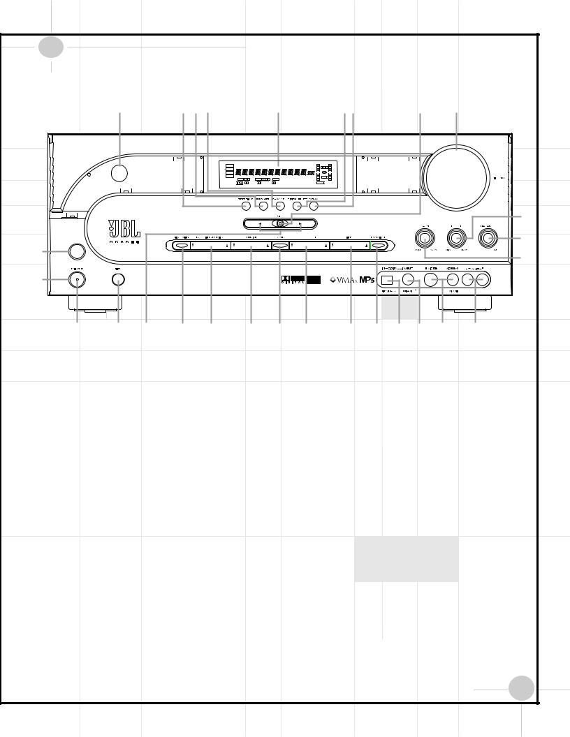
DCR600 Front Panel Controls
|
ˆ |
ı Ù Û |
|
|
Ú |
|
|
|
Ò |
Ô Ó |
|
|
DTS |
MUTE |
|
AUTO TUNED ST MEMORY PRESET O |
|
|
O |
|
|
|
|
DOLBY D |
|
|
|
SLEEP L |
0 |
C 0 |
R |
|
|
|
|
|
|
O |
|
|
O |
|
|
|
|
PCM |
|
|
|
O |
|
|
O |
|
|
|
MP3 |
|
|
|
|
|
|
||
|
|
|
|
|
LS |
|
LFE |
RS |
|
|
|
|
|
OPTICAL 1 |
2 |
COAXIAL 1 2 3 ANALOG VMAx NF 5.1 LOGIC 7 CM |
O |
|
|
O |
|
|
|
|
|
DIGITAL |
PRO LOGIC 3-STEREO 5 CH STEREO HALL 1 |
THEATER NIGHT |
|
|
|
|
|
|
|
|
|
|
|
|
|
|
( |
|
|
|
|
|
|
|
|
|
|
* |
1 |
|
|
|
|
|
|
|
|
|
& |
|
|
|
|
|
|
|
|
|
|
|
2 |
|
|
|
|
|
|
|
|
|
|
3 |
4 5 |
6 7 |
|
8 9 º) ! @ # $ % ^ |
||||||
1Main Power Switch: Press this button to |
of headphones. Be certain that the headphones |
are not always available. (See page 52 for |
||||
apply power to the DCR600. When the switch |
have a standard 1/4" stereo phone plug. Note |
more information about surround modes.) |
||||
is pressed in, the unit is placed in a Standby |
that the main room speakers will automatically |
8Tuning Selector: Press the left side of the |
||||
mode, as indicated by the amber Power |
be turned off when the headphone jack is in use. |
|||||
Indicator 3surrounding the System Power |
|
button to tune lower-frequency stations and |
||||
5Selector Buttons: When you are estab- |
the right side of the button to tune higher- |
|||||
Control 2. This button MUST be pressed in |
||||||
lishing the DCR600’s configuration settings, |
frequency stations. When a station with a strong |
|||||
to operate the unit. To turn the unit off and |
||||||
use these buttons to select from the choices |
signal is reached, the TUNED indicator Uwill |
|||||
prevent the use of the remote control, this |
||||||
available, as shown in the Main Information |
be illuminated in the Main Information |
|||||
switch should be pressed until it pops out from |
||||||
Display Ú. |
Display Ú. |
|||||
the front panel so that the word “OFF” may be |
||||||
|
|
|
|
|
||
read at the top of the switch. |
6Tone Mode: Pressing this button enables |
To tune manually, tap the button lightly and |
||||
|
||||||
|
|
|
|
|
||
NOTE: |
or disables the Bass and Treble tone controls. |
note that the tuner will step up one frequency |
||||
This switch is normally left in the “ON” position. |
When the button is pressed so that the words |
increment per button press. When the button is |
||||
TONE IN appear in the Main Information |
held for a few seconds you will note that the |
|||||
|
||||||
2System Power Control: When the Main |
Display Ú, the settings of the Bass &and |
unit will quickly search the |
frequency band. |
|||
Power Switch 1is “ON,” press this button |
Treble (controls may be used to adjust the |
Release it once the fast tuning starts; the tuner |
||||
to turn on the DCR600; press it again to turn |
output signals. When the button is pressed so |
will automatically scan for the next station |
||||
the unit off. Note that the Power Indicator |
that the words TONE OUT appear in the Main |
with an acceptable signal and then stop. |
||||
3in the center of the switch will turn green |
Information Display Ú, the output signal |
|
|
|
|
|
when the unit is on. |
will be “flat,” without any bass or treble alter- |
9Tuner Band Selector: Pressing this button |
||||
|
ation, no matter how the actual Bass and |
will automatically switch the DCR600 to the |
||||
3Power Indicator: This LED will be illumi- |
Treble &(controls are adjusted. |
Tuner mode. Pressing it again will switch |
||||
nated in amber when the unit is in the Standby |
7Surround Mode Selector: Press this but- |
between the AM and FM frequency bands. |
||||
mode to signal that the unit is ready to be |
)Preset Stations Selector: Press this |
|||||
turned on. When the unit is in operation, the |
ton to change the surround mode by scrolling |
|||||
indicator will turn green. |
through the list of available modes. Note that |
button to scroll up or down through the list or |
||||
|
depending on the type of input, some modes |
stations that have been entered into the preset |
|
|
||
|
|
|||||
4Headphone Jack: This jack may be used |
|
memory. |
|
|
||
to listen to the DCR600’s output through a pair |
|
|
|
|
|
|
|
|
|
|
|
||
13
!Input Source Selector: Press this button |
&Bass Control: Turn this control to modify |
normal brightness. When HALF appears, the |
|||||||
to change the input by scrolling up or down |
the low-frequency output of the left/right |
display is at half the normal brightness level. |
|||||||
through the list of input sources. When an |
channels by as much as ±10dB. Set this control |
When OFF appears, all of the indicators in |
|||||||
audio source is selected, the last video input |
to a suitable position for your taste or room |
the Main Information Display Úwill go |
|||||||
used remains routed to the Video 1 Output a |
acoustics. |
dark. Note, however, that the Power |
|||||||
and Video Monitor Output ‚. This permits |
*Balance Control: Turn this control to |
Indicator 3will always remain lit to remind |
|||||||
you to simultaneously view and listen to |
you that the unit is turned on. |
||||||||
different sources. |
|
|
|
change the relative volume for the front |
Once the desired brightness level is selected, |
||||
|
|
|
|
|
left/right channels. |
||||
@FM Mode Selector: Press this button to |
|
it will remain in effect until it is changed again |
|||||||
select |
Auto or Manual tuning. When the but- |
NOTE: |
or until the unit is turned off. |
||||||
ton is pressed so that the AUTO indicator V |
|
|
|
||||||
lights, the tuner will search for the next station |
For proper operation of the surround modes |
Delay: Press this button to begin the |
|||||||
with |
an acceptable signal when the Tuning |
this control should be at the midpoint, or |
sequence of steps required to enter delay time |
||||||
Selector 8 |
49 is pressed. When the |
“12 o’clock,” position. |
settings. |
||||||
button |
is pressed so that the AUTO indicator |
(Treble Control: Turn this control to modify |
ÒDigital Input Selector: When playing a |
||||||
Vis not lit, each press of the Tuning Selector |
|||||||||
the high-frequency output of the left/right |
source that has a digital output, press this |
||||||||
8 |
49 will increase the frequency. |
||||||||
channels by as much as ±10dB. Set this control |
button to select between the Optical #e |
||||||||
|
|
|
|
|
|||||
NOTE: When the FM reception of a station is |
to a suitable position for your taste or room |
and Coaxial $f Digital inputs. |
|||||||
weak, audio quality will be increased by |
acoustics. |
ÚMain Information Display: This display |
|||||||
switching to Mono mode by pressing the |
ÓVolume Control: Turn this knob clockwise |
||||||||
delivers messages and status indications to |
|||||||||
FM (Tuning) Mode Button @ |
until the |
||||||||
to increase the volume, counterclockwise to |
help you operate the receiver. |
||||||||
STEREO Indicator Tgoes out. |
|
||||||||
|
decrease the volume. If the DCR600 is muted, |
|
|
|
|||||
|
|
|
|
|
ÛChannel Select Button: Press this button |
||||
#Digital Optical 2 Input: Connect the |
adjusting the volume control will automatically |
||||||||
optical digital output of an audio or video |
release the unit from the silenced condition. |
to begin the process of trimming the channel |
|||||||
product to this jack. When the Input is not in |
ÔSet Button: When making choices during |
output levels using an external audio source. |
|||||||
|
|
|
|||||||
use, be certain to keep the plastic cap installed |
ÙSpeaker Select Button: Press this button |
||||||||
to avoid dust contamination that might |
the setup and configuration process, press this |
||||||||
button to enter the desired setting as shown in |
to begin the process of selecting the speaker |
||||||||
degrade future performance. |
|
||||||||
|
the Main Information Display Úinto the |
positions that are used in your listening room. |
|||||||
|
|
|
|
|
|||||
$Digital Coax 3 Jack: This jack is used for |
DCR600’s memory. The Set button may also be |
ıTest Tone Selector: Press this button |
|||||||
connection to the output |
of portable audio |
used to change the display brightness, to avoid |
|||||||
devices, video game consoles or other products |
interfering with video presentations: |
to begin the process of adjusting the channel |
|||||||
output levels using the internal test tone as |
|||||||||
that have a coax digital jack. |
|
|
|||||||
|
Press and hold the Set Button Ôon the front |
a reference. |
|||||||
|
|
|
|
|
|||||
%Video 4 Video Input Jacks: These jacks |
panel for three seconds until the message in |
ˆRemote Sensor Window: The sensor |
|||||||
may be used for temporary connection to the |
the Main Information Display Úreads |
||||||||
behind this window receives infrared signals |
|||||||||
composite or S-Video output of video games, |
VFD FULL. Within five seconds, press the |
||||||||
from the remote control. Aim the remote at |
|||||||||
camcorders or other portable video products. |
front panel Selector Buttons 5until the |
||||||||
this area and do not block or cover it unless an |
|||||||||
|
|
|
|
|
desired brightness display level is shown. |
||||
|
|
|
|
|
external remote sensor is installed. |
||||
^Video 4 Audio Input Jacks: These |
Press the Set Button Ôagain to enter the |
||||||||
|
|
|
|||||||
audio/video jacks may be used for temporary |
setting. |
|
|
|
|||||
connection to video games or portable |
|
|
|
|
|||||
audio/video products such as camcorders and |
When FULL appears in the Main |
|
|
|
|||||
|
|
|
|
|
|
|
|||
portable audio players. |
|
Information Display Ú, the display is at its |
|
|
|
||||
|
|
|
|
|
|
|
|
|
|
|
|
|
|
|
|
|
|
|
|
|
|
|
|
|
|
|
|
|
|
14
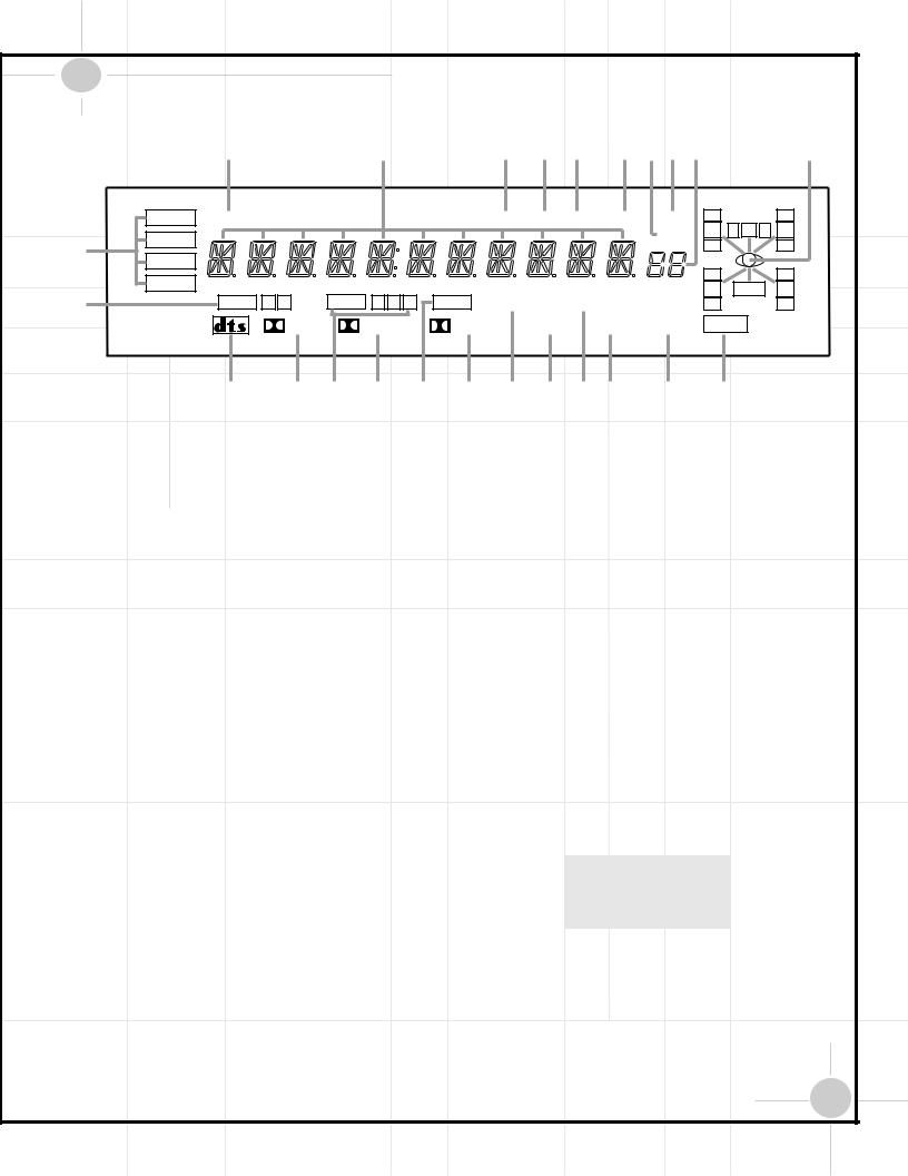
|
|
DCR600 Front Panel Information Display |
|
|
|
|
|
||||
|
|
X |
|
W |
V U T |
SRQP |
|
|
|
O |
|
|
DTS |
MUTE |
|
|
AUTO TUNED ST |
MEMORY PRESET |
O |
|
|
|
O |
|
|
|
L |
0 |
C |
0 |
R |
||||
|
DOLBY D |
|
|
|
|
SLEEP |
|||||
A |
|
|
|
|
|
O |
|
|
|
O |
|
PCM |
|
|
|
|
|
|
|
|
|
|
|
|
|
|
|
|
|
O |
|
|
|
O |
|
|
MP3 |
|
|
|
|
|
|
|
|
||
|
|
|
|
|
|
LS |
|
LFE |
|
RS |
|
B |
|
OPTICAL 1 |
2 |
COAXIAL 1 2 3 |
ANALOG VMAx NF 5.1 LOGIC 7 CM |
|
|
||||
|
O |
|
|
|
O |
||||||
|
|
|
DIGITAL |
PRO LOGIC |
3-STEREO 5 CH STEREO |
HALL THEATER |
NIGHT |
|
|
|
|
|
|
C D E F G H I J KL M N |
|
|
|
||||||
ABitstream Indicators: When the input is |
KLogic 7 Mode: Indicates that the Logic 7 |
PPreset Number/Sleep Timer: In Tuner |
||
a digital source, these indicators display the |
mode is in use. LOGIC 7C appears for the |
mode these numbers indicate the preset mem- |
||
specific type of data signal. |
Cinema version of Logic 7; LOGIC 7M |
ory location in use. In Sleep function mode it |
||
BOptical Source: Indicates an Optical |
appears for the Music version of Logic 7. |
shows the number of minutes remaining before |
||
|
|
the unit goes into the Standby mode. |
||
Digital Input has been selected. |
LHall Mode: Lights when the Hall mode |
|||
QPreset Indicator: This indicator lights |
||||
|
||||
CDTS: Indicates a DTS-encoded source. |
has been selected. |
|||
|
|
when the tuner is in use to show that the |
||
|
MTheater Mode: Indicates that the Theater |
|||
DDolby Digital: Indicates a Dolby Digital |
Preset Number/Sleep Timer Pis showing |
|||
mode has been selected. |
||||
source. |
the station’s preset memory number. |
|||
|
|
|||
ECoaxial Source: Indicates a Coaxial |
NNight Mode: Indicates that the DCR600 |
RSleep Indicator: This indicator lights |
||
is in the Night mode, which preserves the |
||||
Digital Input. |
when the Sleep function is in use. |
|||
dynamic range of digital program material |
||||
|
|
|||
FDolby Pro Logic: Indicates the Dolby |
at low volume levels. |
SMemory: Flashes when entering presets |
||
Pro Logic mode has been selected. |
OSpeaker/Channel Input: These indicators |
and other information into the tuner’s memory. |
||
|
|
|||
GAnalog Input: Indicates an analog input |
are multipurpose, indicating either the speaker |
TStereo: Lights when an FM station is |
||
source. |
type selected for each channel or the incoming |
being tuned in stereo. |
||
NOTE: Analog audio input is not available |
data-signal configuration. The left, center, |
UTuned: Lights when a station is being |
||
right, right surround and left surround speaker |
||||
when the DVD input is in use. |
indicators are composed of three boxes, while |
received with sufficient signal strength to pro- |
||
|
vide acceptable listening quality. |
|||
HDolby 3 Stereo Indicator: This indicator |
the subwoofer is a single box. The center box |
|||
|
||||
lights when the Dolby 3 Stereo Mode has been |
lights when a “Small” speaker is selected, and |
VAuto: Lights when the tuner is in Auto |
||
selected. |
all three boxes light when “Large” speakers |
mode. |
||
|
|
|
|
|
IVMAx Mode: Lights when the VMAx |
are selected. When none of the boxes are lit |
|
WMain Information Display: Shows mes- |
|
for the center, surround or subwoofer channels, |
|
|||
mode is in use. VMAx F appears when the |
no speaker has been selected for one of those |
|
sages relating to the status, input source, sur- |
|
Far Field VMAx mode is selected; VMAx N |
|
round mode, tuner, volume level or other |
||
positions. The letters inside each of the center |
|
|||
appears when the Near Field VMAx mode is |
|
aspects of operation. |
||
boxes display active input channels. For stan- |
|
|||
|
|
|
||
selected. |
dard analog inputs, only the L and R will light, |
XMute: Lights to indicate that the unit has |
||
|
||||
J5-Channel Stereo: Lights when the 5- |
indicating a stereo input. When a digital |
been put in Mute by pressing the Mute |
||
Channel Stereo mode has been selected. |
source is playing, the indicators will light to |
Button c. Press the Mute button again to |
||
|
display the channels being received at the digi- |
return to the previously selected output level. |
||
|
tal input. When the letters flash, the digital |
|
||
|
input has been interrupted. |
|
||
15

DCR600 Rear Panel Connections
27 26
L |
R |
VID 3 |
OPTICAL |
VID 3 |
|
|
IN |
|
|
||
|
|
IN |
|
IN |
|
|
TAPE |
|
|
|
|
|
OUT |
VID 2 |
DIGITAL IN |
VID 2 |
|
|
|
IN |
IN |
|
|
ANTENNA |
L |
R |
COAXIAL |
VIDEO |
S-VIDEO |
|
1 |
||||
|
|
|
|
|
|
|
|
|
(DVD) |
|
|
AM |
|
IN |
|
IN |
|
|
|
VID 1 |
2 |
VID 1 |
|
|
|
|
|
||
GND |
|
OUT |
|
OUT |
|
|
|
|
OPT |
|
|
FM |
L |
R |
|
DVD |
|
|
|
|
IN |
|
|
75Ω |
|
|
|
|
|
|
|
CD |
|
MON. |
|
|
|
IN |
DIGITAL OUT |
OUT |
|
|
|
|
|
|
Manufactured under license from Digital Theater Systems, Inc. US Pat. No 5,451,942 and other world-wide patents issued and pending. "DTS", "DTS Digital Surround", are trademarks of Digital Theater Systems, Inc. Copyright 1996 Digital Theater Systems, Inc. All Rights Reserved.
Manufactured under license from Dolby Laboratories.
"Dolby", "Pro Logic" and the double-D symbols are trademarks of Dolby Laboratories. Confidential Unpublished Works.
' 1992-1997 Dolby Laboratories, Inc. All rights reserved. LFE/
SUBWOOFER
REMOTE
IN
OUT
This device complies with part 15 of the FCC rules. Operation is subject to the following two conditions: (1) This device may not cause harmful interference, and (2) This device must accept any interference received, including interference that may cause undesired operation.
RIGHT |
LEFT |
CENTER |
FRONT SPKRS (8Ω ) |
SPKR (8Ω ) |
|
|
|
|
AC INPUT |
|
|
|
|
~120V/60Hz A |
|
U.S. Patent Nos. |
|
|
|
|
4,893,342, |
4,910,779, |
4,975,954 |
|
|
5,034,983, |
5,136,651, |
and 5,333,200 |
|
|
Cooper Bauck Transaural Stereo |
|
|
||
|
|
SERIAL NO. |
C U® L US |
MODEL NO. DCR 600 |
|
|
|
||
|
|
|
|
|
|
|
|
LISTED |
|
|
|
|
E191351 |
NORTHRIDGE |
|
|
|
40KK |
|
|
|
|
AUDIO EQUIPMENT |
CALIFORNIA, USA |
CAUTION |
|
|
|
AC OUTLETS |
|
|
|
~120V/60Hz |
|
RISK OF ELECTRIC SHOCK |
|
|
|
UNSWITCHED/100W, 1A MAX |
DO NOT OPEN |
|
|
|
|
AVIS : RISQUE DE CHOC |
|
|
|
|
ÉLECTRIQUE-NE PAS OUVRIR |
|
|
|
|
WARNING: TO REDUCE THE RISK OF FIRE OR ELECTRIC SHOCK, |
|
|
||
DO NOT EXPOSE THIS APPLIANCE TO RAIN OR MOISTURE. |
|
SWITCHED/50W, 0.5A MAX |
||
AVERTISSEMENT: POUR PRÉVENIR LES RISQUES D'INCENDIE |
|
|||
|
|
|||
OU DE CHOC ÉLECTRIQUE, ÉVITER D'EXPOSER CET APPAREIL |
|
|
||
A LA PLUIE OU A L'HUMIDITÉ. |
|
|
|
|
|
|
RIGHT |
LEFT |
|
|
|
SURR. SPKRS |
(8Ω ) |
|
|
|
|
|
IMPORTANT NOTES: |
¡ Tape Inputs: Connect to PLAY/OUT jacks |
•Digital Audio Outputs: |
Connect to the |
|
|||
|
|
A. The AC plug connections should always be |
of an audio recorder. |
same type digital input connector on a CD-R or |
|||||||
|
|
the last connections made when installing an |
™ Tape Outputs: Connect to RECORD/INPUT |
MiniDisc recorder. |
|||||||
|
|
A/V system. When making subsequent connec- |
|
|
|
||||||
|
|
jacks of an audio recorder. |
ª DVD Video Inputs: Connect to composite |
||||||||
|
|
tions to audio source equipment or speakers, it |
|||||||||
|
|
|
|
|
or S-Video output jacks on a DVD. |
||||||
|
|
is always a good practice to unplug the unit |
£ Video 1 Audio Inputs: Connect jacks to |
||||||||
|
|
|
|
|
|||||||
|
|
from the AC wall outlet. This prevents the pos- |
|
|
|
||||||
|
|
the PLAY/OUT audio jacks on a VCR or other |
‚ Video Monitor Outputs: Connect to com- |
||||||||
|
|
sibility of sending audio or transient signals to |
|||||||||
|
|
video source. |
posite or S-Video input of a TV monitor or |
||||||||
|
|
the speakers that may damage them. |
|||||||||
|
|
|
|
|
video projector. |
||||||
|
|
|
|
|
|
¢ AM Antenna: Connect to the AM loop |
|||||
|
|
B. Connect devices as per the Quick Setup |
|
|
|
||||||
|
|
antenna supplied. If an external AM antenna is |
⁄ LFE/Subwoofer Output: Connect to the |
||||||||
|
|
Guide or per pages 6 through 8 of this manual. |
|||||||||
|
|
used, make connections to the AM and GND |
LFE or line-level input of a powered subwoofer. |
||||||||
|
|
|
|
|
|
||||||
|
|
C. The DCR600 offers both composite and S- |
terminals |
in |
accordance with the instructions |
¤ Front Speaker Outputs: Connect to |
|||||
|
|
supplied |
with the antenna. |
||||||||
|
|
Video inputs and outputs. However, either S |
|||||||||
|
|
|
|
|
matching + and – terminals on front left/right |
||||||
|
|
or composite input/output connections should |
|
|
|
||||||
|
|
Video 1 Audio Outputs: Connect to the |
speakers. |
||||||||
|
|
be used throughout the system in order for it to |
|||||||||
|
|
RECORD/INPUT audio jacks on a VCR or |
|||||||||
|
|
function properly. Do not use S-Video and com- |
‹ Center Speaker Outputs: Connect to |
||||||||
|
|
other video recorder. |
|||||||||
|
|
posite video connections interchangeably. |
|
|
|
matching + and – terminals on center speaker. |
|||||
|
|
|
|
|
|
|
|
|
|||
|
|
D. The digital outputs are active only when a |
§ FM Antenna: Connect to the supplied |
› Surround Speaker |
Outputs: Connect |
to |
|||||
|
|
indoor, or an optional external, FM antenna. |
|||||||||
|
|
digital signal is present, and they do not con- |
|||||||||
|
|
|
|
|
matching + and – terminals |
on left and right |
|
||||
|
|
vert an analog input to a digital signal, or |
|
|
|
|
|||||
|
|
¶ CD Inputs: Connect to output of a CD player. |
surround speakers. |
|
|
||||||
|
|
change the format of the digital signal. In |
|
|
|
|
|
|
|||
|
|
addition, any digital recorder used must be |
NOTE: When the CD player has both fixed and |
NOTE: When making speaker connections |
|
||||||
|
|
compatible with the output signal. For exam- |
variable audio outputs, it is best to use the |
always make certain to maintain correct |
|
||||||
|
|
ple, |
the PCM digital input from a CD player |
fixed output unless you find that the input to |
polarity by connecting the red (+) terminals |
on |
|||||
|
|
|
|
||||||||
|
|
may be recorded on a CD-R or MiniDisc, but |
the receiver is so low that the sound is noisy, |
the DCR600 to the red (+) terminals on the |
|||||||
|
|
Dolby Digital or DTS signals may not. |
or so high that the signal is distorted. |
speakers and the black (–) terminals on the |
|||||||
|
|
|
|
|
|
|
|
|
DCR600 to the black (–) terminals on the |
||
|
|
|
|
|
|
|
|
|
speakers. |
||
|
|
16 |
|
|
|
|
|
|
|||
|
|
|
|
|
|
|
|
|
|
|
|
|
|
|
|
|
|
|
|
|
|
|
|
|
|
|
|
|
|
|
|
|
|
|
|

|
|
|
|
|
|
|
|
|
|
|
fi |
Switched AC Accessory Outlet: Used to |
a Video 1 Video Outputs: Connect to |
|
|
||||
|
|||||||||
|
power any device you wish to have turned on |
RECORD/INPUT composite or S-Video jack on |
|
|
|||||
|
|||||||||
|
when the receiver is turned on with the |
a VCR or other video receiver. |
|
|
|||||
|
System Power Control 2switch. |
bVideo 1 Video Inputs: Connect to |
|
|
|
||||
|
|
|
|
|
|
||||
|
NOTE: Many audio and video products go into |
PLAY/OUT composite or S-Video jacks on a |
|
|
|||||
|
a Standby mode when they are used with |
VCR or other video source. |
|
|
|||||
|
switched outlets, and cannot be fully turned on |
c Video 3 Video Inputs: Connect to |
|
|
|
||||
|
using the outlet alone without a remote control |
|
|
||||||
|
command. The JBL Cinema ProPack 600 remote |
PLAY/OUT composite or S-Video jacks on a |
|
|
|||||
|
offers ALL OFF and ALL ON commands. If a |
VCR or other video source. |
|
|
|||||
|
device is programmed into the remote, do not |
d Video 2 Video Inputs: Connect to |
|
|
|
||||
|
use the switched outlet to power the device. |
|
|
||||||
|
PLAY/OUT composite or S-Video jacks on a |
|
|
|
|||||
|
|
|
|
|
|
||||
|
fl Unswitched AC Accessory Outlet: Used |
VCR or other video source. |
|
|
|||||
|
to power any AC |
device. The power will |
e Optical Digital Input: Connect to optical |
|
|
|
|||
|
remain on at this |
outlet regardless of whether |
|
|
|||||
|
digital output of a digital source. The signal |
|
|
|
|||||
|
the receiver is on |
or off. |
|
|
|||||
|
may be either a Dolby Digital signal, a DTS sig- |
|
|
|
|||||
|
|
|
|
|
|
||||
|
NOTE: The total |
power consumption of all |
nal or a standard PCM digital source. |
|
|
||||
|
devices connected |
to the accessory outlets |
f Coaxial Digital Inputs: Connect to coax |
|
|
|
|
||
|
should not exceed |
100 watts. |
|
|
|
||||
|
digital output of a digital source. The signal |
|
|
|
|
||||
|
|
|
|
|
|
|
|||
|
‡ AC Power Cord: Connect the AC plug to |
may be either a Dolby Digital signal, DTS sig- |
|
|
|
||||
|
an unswitched AC wall output. |
nal or a standard PCM digital source. Do not |
|
|
|
||||
|
connect the RF digital output of an LD player to |
|
|
|
|
||||
|
|
|
|
|
|
|
|||
|
° Remote IR Output: Permits the IR sensor |
these jacks. |
|
|
|
||||
|
|
||||||||
|
in the receiver to serve other remote-controlled |
g Video 3 Audio Inputs: Connect to |
|
|
|
||||
|
devices. Connect this jack to the “IR IN” jack |
|
|
||||||
|
PLAY/OUT audio jacks on a VCR or other |
|
|
|
|||||
|
on the DVD600 or other compatible equipment. |
|
|
||||||
|
|
|
|
video source. |
|
|
|||
|
· Remote IR Input: If the DCR600’s front |
h Video 2 Audio Inputs: Connect to |
|
|
|
||||
|
panel IR sensor is blocked due to cabinet doors |
|
|
||||||
|
|
|
|
|
|
|
|||
|
or other obstructions, an external IR sensor |
PLAY/OUT audio jacks on a VCR or other |
|
|
|||||
|
video source. |
|
|
|
|||||
|
may be used. Connect the output of the sensor |
|
|
||||||
|
|
|
|
|
|
|
|||
|
to this jack. |
|
|
|
|
|
|
||
|
|
|
|
|
|
|
|
|
|
|
|
|
|
|
|
|
|
|
|
|
|
|
|
|
|
|
|
|
|
17
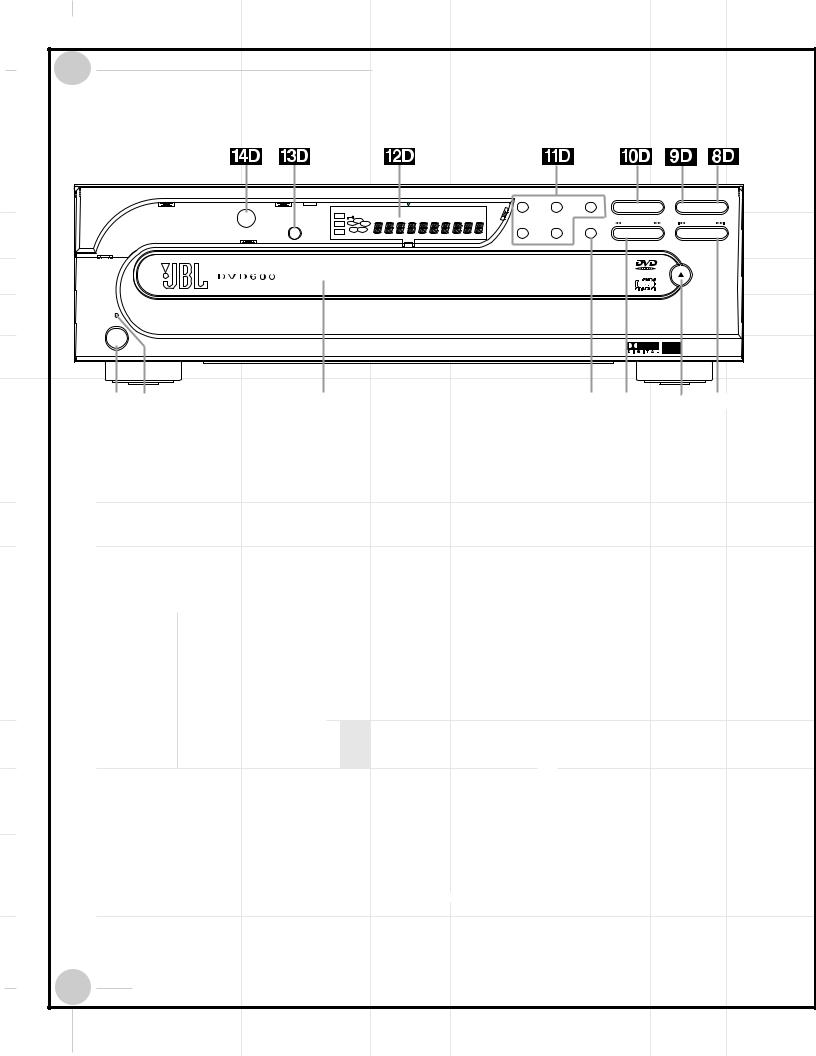
DVD600 Front Panel Controls
|
|
|
|
|
|
|
|
|
|
1 |
2 |
3 |
play |
pause |
stop |
|
DVD |
|
—±‚ RESUME |
RANDOM REPEAT |
1ALL |
DISC |
A – B |
PROG. |
|
|
|
|
|
|
|
|
|
1 |
TITLE |
CHAPTER TRACK |
HOUR |
|
MIN |
INTRO |
SEC |
|
|
|
|
|
|
|
|
|
|
|
disc skip |
search |
|
skip |
|||||||
Dimmer |
CD |
5 |
2 |
|
|
|
|
|
4 |
5 |
|
||||
DISC |
|
|
|
|
|
|
|||||||||
|
VCD |
4 |
|
3 |
|
|
|
|
|
|
|
|
|
|
|
|
|
|
|
|
|
|
|
|
|
|
|
|
|
|
|
|
|
|
|
|
|
|
|
|
|
|
|
|
|
|
open/close |
power |
|
|
|
|
|
|
|
|
|
|
|
|
|
|
|
|
|
|
|
|
|
|
|
|
|
|
|
|
|
|
|
|
|
|
|
|
|
|
|
|
|
|
|
|
|
|
|
|
|
|
|
|
Power Switch: Press to apply power to |
on-screen display. Once you have selected the |
picture will be displayed when the button is |
||||||||||||||||||||||||||||
|
1D |
||||||||||||||||||||||||||||||||
the |
DVD600. When the |
|
unit is first turned on, |
desired speed, release the button and the disc |
pressed. |
||||||||||||||||||||||||||||
|
|||||||||||||||||||||||||||||||||
the Status Indicator |
|
2D |
will turn amber, |
will continue to search at fast speed. To |
|
|
Play: Press to begin playback of a disc, |
||||||||||||||||||||||||||
indicating that it is in |
|
Standby mode. To turn |
resume normal playback speed, press the Play |
|
10D |
||||||||||||||||||||||||||||
|
|
|
|||||||||||||||||||||||||||||||
the unit on, press the |
|
Open/Close Button |
button. |
or to resume playback after the Pause Button |
|||||||||||||||||||||||||||||
|
|
|
|
|
|
|
|
|
|
|
|
|
|
|
|
|
|
|
|
|
|
|
9D |
has been pressed. |
|||||||||
|
6D |
|
or Play Button |
10D |
|
, or use the remote |
|
|
|
|
|
|
|
|
|
|
|||||||||||||||||
|
|
|
|
|
|
|
|
|
|
|
|||||||||||||||||||||||
control to select DVD d, and then power the |
|
6D |
Open/Close Button: Press to open or |
|
|
|
|
|
|
|
|
|
|
|
|
||||||||||||||||||
|
|
|
|
|
|
|
|
|
|
|
|
|
|
||||||||||||||||||||
unit on b. |
close the Disc Tray |
3D |
. |
|
11D |
Direct Access Buttons: Press one of |
|||||||||||||||||||||||||||
|
|
|
|||||||||||||||||||||||||||||||
|
|
|
|
|
|
|
|
|
|
|
|
|
|
|
|
|
|
|
|
|
|
these buttons to play any of the five discs |
|||||||||||
|
|
|
|
Status Indicator: When the DVD600 is |
|
7D |
Skip Forward/Reverse: Press to move |
loaded in the Disc Tray. |
|||||||||||||||||||||||||
|
2D |
|
|||||||||||||||||||||||||||||||
|
|
||||||||||||||||||||||||||||||||
in the On mode, this indicator will glow green. |
forward or backward through the music tracks |
|
|
|
Information Display: This display con- |
||||||||||||||||||||||||||||
When the unit is in Standby, the indicator will |
or chapters on a disc. |
|
12D |
||||||||||||||||||||||||||||||
|
|
||||||||||||||||||||||||||||||||
glow amber. |
|
|
|
Stop: Press once to place the disc in the |
tains a variety of indicators that provide infor- |
||||||||||||||||||||||||||||
|
|
|
|
|
|
|
|
|
|
|
|
|
|
8D |
|
mation about the status of the DVD600 and the |
|||||||||||||||||
|
|
|
|
|
|
|
|
|
|
|
|
|
|
|
|||||||||||||||||||
|
|
|
|
|
|
|
|
|
|
|
|
|
|
|
|
||||||||||||||||||
|
|
|
|
Disc Tray: Holds up to five DVD or CD |
Resume mode, which means that playback will |
disc currently playing. |
|||||||||||||||||||||||||||
|
3D |
||||||||||||||||||||||||||||||||
discs that can be played one at a time in the |
stop, but (as long as the tray is not opened or |
|
|
|
Display Dim: Press this button to adjust |
||||||||||||||||||||||||||||
DVD600. |
the disc changed) DVD playback will continue |
|
13D |
|
|||||||||||||||||||||||||||||
|
|
||||||||||||||||||||||||||||||||
|
|
|
|
|
|
|
|
|
|
|
|
|
from the same point on the disc when the Play |
the brightness of the Information Display by |
|||||||||||||||||||
|
|
|
|
Disc Skip: Press to change the disc |
button is pressed again. Resume will also work |
50% or to turn the display off completely in the |
|||||||||||||||||||||||||||
|
4D |
||||||||||||||||||||||||||||||||
being played. Each press of the button will |
if the unit was turned off. To stop a disc and |
following order: FULL BRIGHTNESS HALF |
|||||||||||||||||||||||||||||||
move the tray forward to the next occupied |
have play start from the beginning, press the |
BRIGHTNESS OFF FULL BRIGHTNESS. |
|||||||||||||||||||||||||||||||
|
|
|
|
|
|
|
|
|
|
|
|
|
|
|
|
|
|
|
|
|
|
|
|
|
|
|
|
|
|
|
|
|
|
position in the tray, skipping over the empty |
button twice. |
|
|
|
Remote Sensor: The sensor that |
||||||||||||||||||||||||||||
disc positions. |
|
|
|
|
|
|
|
|
|
|
14D |
|
|||||||||||||||||||||
|
|
|
Pause: Press to momentarily pause |
|
|
||||||||||||||||||||||||||||
|
|
|
|
|
|
|
|
|
|
|
|
|
|
9D |
receives the infrared commands from the |
||||||||||||||||||
|
|
|
|
|
|
|
|
|
|
|
|
|
|
|
|||||||||||||||||||
|
|
|
|
Search Forward/Reverse: Press to |
playback. To resume playback, press the button |
remote control is behind this area. Do not |
|||||||||||||||||||||||||||
|
5D |
||||||||||||||||||||||||||||||||
move forward or backward through a disc at |
again, or press the Play Button |
10D |
. If a |
cover or obscure this part of the front panel, in |
|||||||||||||||||||||||||||||
|
|||||||||||||||||||||||||||||||||
one of four speeds. Each press and release will |
DVD is playing, action will freeze and a still |
order to avoid a malfunction with the remote. |
|||||||||||||||||||||||||||||||
increase the search speed, as indicated in the |
|
|
|
|
|
|
|
|
|
|
|
|
|
|
|
|
|
|
|
|
|
||||||||||||
18
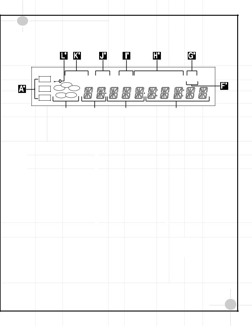
DVD600 Front Panel Information Display
DVD |
|
—±‚ RESUME |
RANDOM REPEAT |
1ALL |
DISC |
A – B |
PROG. |
|
|
|
TITLE |
CHAPTER |
TRACK |
HOUR |
|
MIN |
INTRO |
SEC |
|
|
|
|
|||||||
CD |
|
1 |
|
|
|
|
|
|
|
5 |
2 |
|
|
|
|
|
|
|
|
|
4 |
DISC |
|
|
|
|
|
|
|
VCD |
3 |
|
|
|
|
|
|
|
|
|
|
|
|
|
|
|
|
|
|
|
|
|
|
|
|
|
|
|
|
|
|
|
|
|
|
|
|
|
|
|
|
|
|
|
|
|
|
|
|
|
|
|
|
|
|
|
|
|
|
|
|
|
|
|
|
|
|
|
|
|
|
|
|
|
|
|
|
|
|
|
|
Disc Type: Lights to show the type of disc |
|
|
Intro: Lights when the Intro Scan function |
disc plays at 16x normal speed. For CDs, only |
|||||||||||||
|
|
|
|
||||||||||||||||
|
|
|
|
||||||||||||||||
currently being played. |
is active. |
the first three Fast Search modes are available. |
|||||||||||||||||
|
|
Disc Number: Shows if a disc is loaded |
|
|
Program: Lights during programming. |
›±Lights when the disc is paused. |
|||||||||||||
|
|
|
|
||||||||||||||||
|
|
|
|
||||||||||||||||
in a tray position. The indicator for the disc in |
|
|
|
|
|
|
‹‹Lights when the disc is in the Fast Search |
||||||||||||
play flashes. Note that if a disc is added to, or |
|
|
Repeat: Lights to indicate any of the |
||||||||||||||||
|
|
||||||||||||||||||
removed from, the tray while a disc is playing, |
Repeat modes. |
Reverse mode. For DVDs, when both triangles |
|||||||||||||||||
the indicator will not show the change until all |
|
|
|
|
|
|
glow steadily, the disc plays at 2x normal |
||||||||||||
discs are cycled. |
|
|
Random: Lights when the unit is in the |
speed. When the left triangle is flashing, the |
|||||||||||||||
|
|
||||||||||||||||||
|
|
|
|
|
|
|
Random Play mode. |
disc plays at 4x normal speed. When the right |
|||||||||||
|
|
Title: Shows the DVD title number cur- |
|
|
|
|
|
|
triangle is playing, the disc plays at 8x normal |
||||||||||
|
|
|
|
|
|
|
|
||||||||||||
rently playing. |
|
|
Resume: Lights when the Stop button has |
speed. When both triangles are flashing, the |
|||||||||||||||
|
|
||||||||||||||||||
|
|
|
|
|
|
|
been pressed once to put the unit in the |
disc plays at 16x normal speed. For CDs, only |
|||||||||||
|
|
Chapter/Track Number: Shows the |
Resume mode. |
the first three Fast Search modes are available. |
|||||||||||||||
|
|
||||||||||||||||||
current chapter (DVD) or current track |
|
|
|
|
|
|
|
|
Parental Lock Indicator: This indicator |
||||||||||
number (CD). |
|
|
Playback Mode: Lights to show the cur- |
|
|
||||||||||||||
|
|
|
|
|
|
|
rent playback mode: |
lights when the parental-lock system is |
|||||||||||
|
|
Program Time: Shows the running time |
|
|
|
|
|
|
engaged in order to prevent anyone from |
||||||||||
|
|
|
|
|
|
|
|
||||||||||||
of a DVD or current track time, time remaining |
›Lights when a disc is playing in the Normal |
|
changing the rating level without a code. |
||||||||||||||||
in the current track, or the total remaining time |
|
|
|
|
|
|
|
|
|||||||||||
mode. |
|
|
|
|
|
|
|
|
|||||||||||
of a CD. |
|
|
|
|
|
|
|
|
|
|
|
|
|
||||||
|
|
|
|
|
|
|
››Lights when the disc is in the Fast Search |
|
|
|
|
|
|
|
|
||||
NOTE: The Program Time Indicators will also |
Forward mode. For DVDs, when both triangles |
|
|
|
|
|
|
|
|
||||||||||
|
|
|
|
|
|
|
|
|
|
|
|
|
|
|
|
|
|
||
display text messages about the DVD600’s sta- |
glow steadily, the disc plays at 2x normal |
|
|
|
|
|
|
|
|
||||||||||
tus, including Reading when a disc is |
speed. When the right triangle is flashing, the |
|
|
|
|
|
|
|
|||||||||||
loading, Bye when the unit is turned off, and |
disc plays at 4x normal speed. When the left |
|
|
|
|
|
|
|
|||||||||||
Disc Error when a disc not compatible |
triangle is flashing, the disc plays at 8x normal |
|
|
|
|
|
|
|
|||||||||||
with the DVD600 is put into the play position. |
speed. When both triangles are flashing, the |
|
|
|
|
|
|
|
|||||||||||
19
DVD600 Rear Panel Connections
Manufactured under license from Dolby Laboratories. |
|
|
Apparatus Claims of U.S. Patent Nos. |
4,631,603, |
|
|
"DTS" and "DTS Digital Out" are trademarks |
|
|||||||||||
"Dolby", "Pro Logic" and the double-D symbols are trademarks |
|
|
4,577,216, 4,819,098, and 4,907,093 licensed for |
|
|
|
|||||||||||||
|
|
|
|
of Digital Theater Systems, Inc. |
|
||||||||||||||
of Dolby Laboratories. Confidential Unpublished Works. |
|
|
limited viewing uses only. |
|
|
|
|
||||||||||||
|
|
|
|
|
|
|
|
|
|||||||||||
' 1992-1997 Dolby Laboratories, Inc. All rights reserved. |
|
|
|
|
|
|
|
|
|
|
|
|
|
|
|
||||
|
|
|
|
|
|
|
|
|
|
|
|
|
|
|
|||||
This device complies with part 15 of the FCC rules. Operation is |
|
|
CERTIFIFICATION - THIS PRODUCT COMPLIES WITH DHHS |
|
|
|
|
|
|
||||||||||
|
|
|
|
|
RULES 21 CFR, SUBCHAPTER J, PART |
|
|
|
|
|
|
||||||||
subject to the following two conditions; (1) This device may not |
|
|
|
|
|
|
|
|
|
|
|
||||||||
|
|
|
|
|
1040 AT DATE OF MANUFACTURE |
|
|
|
|
|
|
||||||||
cause harmful interference, and (2) This device must accept any |
|
|
|
|
|
|
|
|
|
|
|
||||||||
interference received, including interference that may cause |
|
|
|
|
|
|
|
|
|
|
|
|
|
|
|
||||
undesired operation. |
|
|
|
|
|
|
|
COMPONENT |
|
|
|
|
|
|
|
|
|||
|
|
|
|
|
|
|
|
|
|
VIDEO OUT |
|
|
|
|
|
|
|
|
|
|
DIGITAL |
|
VIDEO OUT |
|
|
|
|
Pr |
|
|
|
|
|
CAUTION |
|
|
|||
|
OUT |
|
|
|
|
|
|
|
|
|
|
|
RISK OF ELECTRIC SHOCK |
|
|
||||
|
|
|
|
|
|
|
|
|
|
|
|
|
|
|
|
DO NOT OPEN |
|
|
|
|
|
|
|
|
|
|
|
|
|
|
|
|
|
|
|
AVIS : RISQUE DE CHOC |
|||
|
COAXIAL |
|
VIDEO |
|
|
|
|
|
|
|
Pb |
|
|
|
|
ÉLECTRIQUE–NE PAS OUVRIR |
|||
|
|
|
|
|
|
|
|
|
|
|
|
|
WARNING: TO REDUCE THE RISK OF FIRE OR ELECTRIC SHOCK, |
||||||
|
|
|
|
|
|
|
|
|
|
|
|
|
|
DO NOT EXPOSE THIS APPLIANCE TO RAIN OR MOISTURE. |
|||||
|
|
|
S-VIDEO |
|
|
|
|
|
|
|
Y |
|
AVERTISSEMENT: POUR PRÉVENIR LES RISQUES D'INCENDIE |
||||||
|
|
|
|
|
|
|
|
|
|
|
OU DE CHOC ÉLECTRIQUE, ÉVITER D'EXPOSER CET APPAREIL |
||||||||
|
|
|
|
|
|
|
|
|
|
|
|
|
|
A LA PLUIE OU A L'HUMIDITÉ. |
|||||
REMOTE |
|
U® L US |
|
AC INPUT |
|
MODEL NO. DVD 600 |
~120V/60Hz 25W |
||
|
C |
|||
IN |
|
|||
|
LISTED |
|
|
|
|
|
E206909 |
NORTHRIDGE |
|
|
|
7H57 |
|
|
|
AUDIO/VIDEO |
CALIFORNIA, USA |
|
|
OUT |
EQUIPMENT |
|
|
|
|
|
|
|
|
1
SERIAL NO.
CLASS 1
LASER PRODUCT
6 |
7 |
|
|
|
Coaxial Digital Output: Connect this jack |
|
Component Video Outputs: If your TV or |
panel Remote Sensor |
14D |
is blocked. This |
|||||
|
|
||||||||||
to the coaxial digital input of an A/V receiver |
video projector has component video inputs, |
jack may also be used with compatible IR |
|||||||||
or surround processor for Dolby Digital, DTS or |
you may connect these output jacks to the set |
remote control-based automation systems. |
|||||||||
PCM |
audio playback. |
for the highest video quality available. Note |
AC Power Cord: Connect this plug to |
||||||||
|
|
that the component video inputs may be |
|||||||||
NOTE: The coaxial digital output should only |
labeled as Y/Pr/Pb or Y/Cr/Cb but, for connec- |
an AC outlet. If the outlet is controlled by a |
|||||||||
be connected to a digital input. Even though it |
tion purposes, they are the same. The outputs |
switch, make certain that it is in the ON |
|||||||||
is the same RCA-type connector as standard |
of these jacks should NOT be connected to a |
position. |
|||||||||
analog audio connections, DO NOT connect it |
standard composite video input. |
|
|
|
|
|
|||||
to a conventional analog input jack. |
|
|
|
|
|
|
|
|
|
|
|
|
|
|
Remote Control Output: Connect this |
|
|
|
|
|
|||
Composite Video Output: Connect this |
jack to the infrared (IR) input jack of another |
|
|
|
|
|
|||||
jack to the video input on a television or video |
JBL or other compatible remote-controlled |
|
|
|
|
|
|||||
projector, or to a video input on an A/V receiver |
product to have the built-in Remote Sensor |
|
|
|
|
|
|||||
or processor if you are using that type of |
|
|
on the DVD600 provide IR signals to |
|
|
|
|
|
|||
|
14D |
|
|
|
|
|
|||||
device |
|
|
|
|
|
|
|
|
|
|
|
for video input switching. |
other |
compatible |
products. |
|
|
|
|
|
|||
S-Video Output: Connect this jack to the |
|
Remote |
Control Input: Connect the out- |
|
|
|
|
|
|||
S-Video input on a television or video projector, |
put of a remote |
infrared sensor, or the remote |
|
|
|
|
|
||||
or to an S-Video input on an A/V receiver or |
control output of another JBL or other compati- |
|
|
|
|
|
|||||
processor if you are using that type of device |
ble product, to this jack. This will enable the |
|
|
|
|
|
|||||
for S-Video input switching. |
remote control to operate even when the front |
|
|
|
|
|
|||||
|
|
|
|
|
|
|
|
|
|
|
|
|
|
|
|
|
|
|
|
|
|
|
|
20

Remote Control Functions
IMPORTANT NOTE: The JBL Cinema ProPack 600 remote control may be programmed to control up to eight devices, including the DCR600 and DVD600. It is helpful to think of the remote as being organized into “pages,” with one page for each device. Depending on which device has been selected, the buttons on that device’s page will perform different functions, as listed starting on the next page. These functions may vary from the labels on the remote, and from one device to the next. Some buttons may perform no function at all for a given device.
In order to go to the page for a particular device, such as the DVD600, you will need to press the Input Selector button for that device
(DVD in this case), located in a grouping just below the power buttons. The remote will then function as if it were dedicated to the DVD600.
If you would like to make an adjustment that affects the DCR600 receiver, such as turning the volume up or down, you must first go to the page for the DCR600 by pressing its Input
Selector button. This button is labeled "Main" on the remote. The exception to this rule is that the DVD600’s transport functions – Play, Forward and Reverse Search, Stop, Pause, and Previous and Next Chapter/Track Skip – may be accessed from the "Main" page, without
having to jump to the DVD page.
21
 Loading...