


TECHNICAL BULLETIN
Poor Hot Start – Tank Pressure
Control Valve – Check Operation
MODEL XJS Range 1995-96 MY
VIN 194775 - 226645
Remove and destroy Bulletin 17-8, dated 5/96.
Replace with this Bulletin.
Revisions are marked with a bar and in
ISSUE:ISSUE:
ISSUE:
ISSUE:ISSUE:
When investigating a customer complaint of poor “hot start” on 1995-96 MY XJS
Range vehicles within the above VIN range, verify that the fuel tank pressure
control valve (Rochester valve) is operating properly.
ACTION:ACTION:
ACTION:
ACTION:ACTION:
After verifying a customer complaint of poor “hot start” (extended cranking) on
1995-96 MY XJS Range vehicles within the above VIN range, check the fuel tank
pressure control valve as follows:
1. Raise vehicle on hoist.
2. Remove the left front wheel.
3. Remove the liner from the wheel well.
DATE 5/96
bold textbold text
bold text.
bold textbold text
17-8
Amended
1/97
4. Disconnect the vacuum hose from the control valve.
5. Connect a vacuum tester to the pressure control valve fitting.
6. Apply a vacuum of
be held
7. Disconnect the vacuum tester from the control valve.
8. If the valve held vacuum, reconnect the vacuum hose and lower the vehicle.
9. If the valve is faulty, cut the retaining strap from the fuel tank vent hose.
Remove the retaining clip and disconnect the vent hose of fuel tank from the
valve.
10. Loosen the retaining clip and disconnect the hose of the carbon canister from
the valve.
11. Remove the defective valve.
12. Check a new valve by applying a vacuum of
as in step 4.
13. Install the new valve after checking.
14. Reconnect the hose of the carbon canister to the valve.
15. Reconnect the vent hose of the fuel tank to the valve. Install a new tie strap.
for 2-3 seconds for 2-3 seconds
for 2-3 seconds, the valve is faulty.
for 2-3 seconds for 2-3 seconds
2.94-14.7 in. Hg. (0.1-0.5 bar)2.94-14.7 in. Hg. (0.1-0.5 bar)
2.94-14.7 in. Hg. (0.1-0.5 bar). If this vacuum cannot
2.94-14.7 in. Hg. (0.1-0.5 bar)2.94-14.7 in. Hg. (0.1-0.5 bar)
2.94-14.7 in. Hg. (0.1-0.5 bar)2.94-14.7 in. Hg. (0.1-0.5 bar)
2.94-14.7 in. Hg. (0.1-0.5 bar)
2.94-14.7 in. Hg. (0.1-0.5 bar)2.94-14.7 in. Hg. (0.1-0.5 bar)
Bulletin Number 17-8 Date of issue 1/97 Page 1 of 2

16. Reconnect the vacuum hose.
17. Reinstall the wheel well fender liner.
18. Reinstall the left front wheel and lower the vehicle.
PP
ARAR
TS INFORMATS INFORMA
P
AR
TS INFORMA
PP
ARAR
TS INFORMATS INFORMA
TION:TION:
TION:
TION:TION:
DESCRIPTIONDESCRIPTION
DESCRIPTION
DESCRIPTIONDESCRIPTION
Fuel tank pressure control valve CBC 7714 1
Tie strap ADU 9028 1
WW
ARRANARRAN
W
ARRAN
WW
ARRANARRAN
FF
AA
ULUL
F
A
UL
FF
AA
ULUL
CODECODE
CODE
CODECODE
BK BB HM 17.15.48 Remove & install fuel tank 0.55 hrs.
TY INFORMATY INFORMA
TY INFORMA
TY INFORMATY INFORMA
TT
T
TT
TION:TION:
TION:
TION:TION:
R.O.R.O.
R.O.
R.O.R.O.
NUMBERNUMBER
NUMBER
NUMBERNUMBER
DESCRIPTIONDESCRIPTION
DESCRIPTION
DESCRIPTIONDESCRIPTION
pressure control valve
PP
ARAR
T NUMBERT NUMBER
P
AR
T NUMBER
PP
ARAR
T NUMBERT NUMBER
QTYQTY
QTY
QTYQTY
TIMETIME
TIME
TIMETIME
ALLALL
ALL
ALLALL
OO
O
OO
WW
ANCEANCE
W
ANCE
WW
ANCEANCE
Page 2 of 2 Date of issue 1/97 Bulletin Number 17-8
TECHNICAL BULLETIN
AIR Pump Clutch –
Intermittent Operation –
17-9
Amended
Service Action S458
MODEL 1993-94 MY 4.0L Sedan & XJS DATE 5/97
Remove and destroy Bulletin 17-9, dated 5/97.
Replace with this Bulletin.
Revisions are marked with a bar and in
ISSUE:ISSUE:
ISSUE:
ISSUE:ISSUE:
Some 1993-94 MY Sedan (4.0L) Range and XJS (4.0L) Range vehicles may
experience intermittent operation of the AIR pump. The operation of the AIR pump
clutch is controlled by a relay located in the engine compartment. The contacts of
this relay may become contaminated by the entry of water or cleaning solutions
containing silicones.
Jaguar Cars will contact all customers with 1993-94 MY Jaguar vehicles within the
above VIN ranges to advise them to make dealer service appointments to verify
proper operation of the relay.
bold textbold text
bold text.
bold textbold text
8/97
AA
CTION:CTION:
A
CTION:
AA
CTION:CTION:
The 1993-94 MY Sedan (4.0L) Range and XJS (4.0L) Range vehicles must be
checked as described below.
For vehicles registered in states
AIR pump clutch as described below.
For vehicles serviced and/or registered
relay with a sealed unit and verify the operation of the AIR pump clutch as
described on the following page.
VEHICLES REGISTERED AND SERVICED OUTSIDE CALIFORNIA
1. Open hood and observe the AIR pump clutch while an assistant starts the
engine. The clutch should engage as cranking begins.
On a hot engine, the clutch should disengage after a few seconds.
On a cold engine, more time will elapse until the clutch disengages at a
coolant temperature of 34°C (95°F). Do not wait until the clutch disengages.
2. If proper operation is observed, no further action is required. Stop the engine
and close the hood.
3. If the AIR pump clutch does not engage, follow normal diagnostic procedures
(refer to AJ6 4.0L Engine Management System/OBD I Diagnostic Guide) and
repair. Submit a claim under normal warranty procedures.
other than Californiaother than California
other than California, verify the operation of the
other than Californiaother than California
in Californiain California
in California, replace the AIR pump clutch
in Californiain California
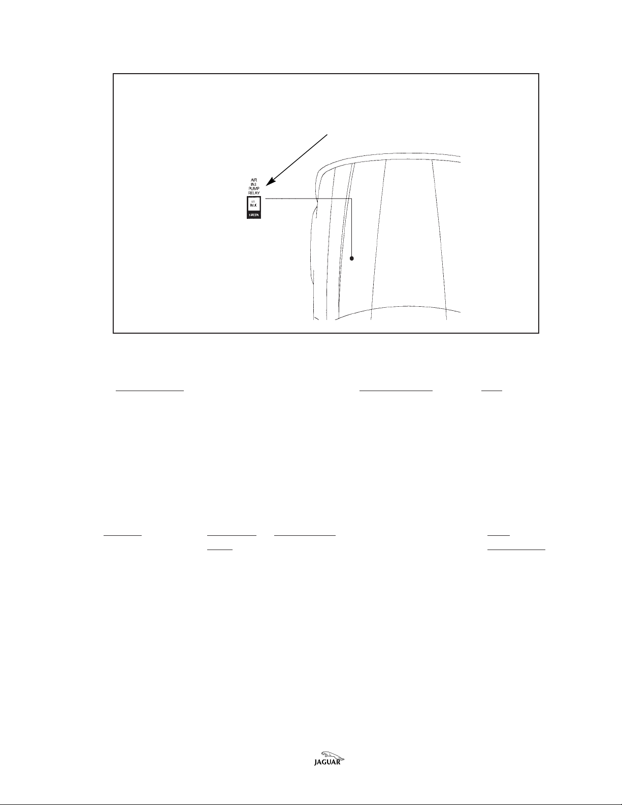
If diagnosis shows that the AIR pump relay
green mounting base on XJS)green mounting base on XJS)
green mounting base on XJS) is defective, install a sealed relay part no. LHF
green mounting base on XJS)green mounting base on XJS)
Bulletin Number 17-9 Amended 8/97 Date of issue 5/97 Page 1 of 5
(red mounting base on S(red mounting base on S
(red mounting base on S
(red mounting base on S(red mounting base on S
edan;edan;
edan;
edan;edan;

6703AA under the terms of this service action.
VEHICLES SERVICED OR REGISTERED IN CALIFORNIA
1. Open hood and replace the AIR pump relay
green mounting base on XJSgreen mounting base on XJS
green mounting base on XJS) with a sealed relay part no. LHF 6703AA.
green mounting base on XJSgreen mounting base on XJS
(red mounting base on S(red mounting base on S
(red mounting base on S
(red mounting base on S(red mounting base on S
edan;edan;
edan;
edan;edan;
2. Observe the AIR pump clutch while an assistant starts the engine. The clutch
should engage as cranking begins.
On a hot engine, the clutch should disengage after a few seconds.
On a cold engine, more time will elapse until the clutch disengages at a
coolant temperature of 34°C (95°F). Do not wait until the clutch disengages.
2. If proper operation is observed, no further action is required. Stop the engine
and close the hood.
3. If the AIR pump clutch does not engage, follow normal diagnostic procedures
(refer to AJ6 4.0L Engine Management System/OBD I Diagnostic Guide) and
repair. Submit a claim under normal warranty procedures.
LL
OCAOCA
TION OF SEDTION OF SED
L
OCA
TION OF SED
LL
OCAOCA
TION OF SEDTION OF SED
FRONFRON
FRON
FRONFRON
AN (4.0L) RANGE AN (4.0L) RANGE
AN (4.0L) RANGE
AN (4.0L) RANGE AN (4.0L) RANGE
T OF T OF
VEHICLEVEHICLE
T OF
VEHICLE
T OF T OF
VEHICLEVEHICLE
11
993 MY993 MY
1
993 MY
11
993 MY993 MY
AIR PUMP RELAAIR PUMP RELA
AIR PUMP RELA
AIR PUMP RELAAIR PUMP RELA
ILLUSTRA TION 1
YY
Y
YY
FRONFRON
FRON
FRONFRON
T OF T OF
T OF
T OF T OF
VEHICLEVEHICLE
VEHICLE
VEHICLEVEHICLE
11
1
11
994 MY994 MY
994 MY
994 MY994 MY
Page 2 of 5 Date of issue 5/97 Bulletin Number 17-9 Amended 8/97
LL
OCAOCA
TION OF XJS (4.0L) RANGE TION OF XJS (4.0L) RANGE
L
OCA
TION OF XJS (4.0L) RANGE
LL
OCAOCA
TION OF XJS (4.0L) RANGE TION OF XJS (4.0L) RANGE
AIR PUMP RELAAIR PUMP RELA
AIR PUMP RELA
AIR PUMP RELAAIR PUMP RELA
YY
Y
YY
AIR PUMP RELAAIR PUMP RELA
AIR PUMP RELA
AIR PUMP RELAAIR PUMP RELA
YY
Y
YY
FRONFRON
T OF T OF
T OF
T OF T OF
VEHICLEVEHICLE
VEHICLE
VEHICLEVEHICLE
FRON
FRONFRON
ILLUSTRA TION 2
PP
ARAR
TS INFORMATS INFORMA
P
AR
TS INFORMA
PP
ARAR
TS INFORMATS INFORMA
DESCRIPTIONDESCRIPTION
DESCRIPTION
DESCRIPTIONDESCRIPTION
TION:TION:
TION:
TION:TION:
PP
ARAR
T NUMBERT NUMBER
P
AR
T NUMBER
PP
ARAR
T NUMBERT NUMBER
Sealed relay LHF 6703AA 1
QTYQTY
QTY
QTYQTY
WW
ARRANARRAN
W
ARRAN
WW
ARRANARRAN
TY INFORMATY INFORMA
TY INFORMA
TY INFORMATY INFORMA
TION:TION:
TION:
TION:TION:
Service Action S458
VEHICLEVEHICLE
VEHICLE
VEHICLEVEHICLE
CALIFORNIACALIFORNIA
CALIFORNIA
CALIFORNIACALIFORNIA
4.0L 1 993-94 MY ST Replace AIR pump relay 0.10 hrs.
Sedan -without drive-in/out time
MODEL CODE (performed with another repair)
4064, 4082
4.0L 1993-94 MY
XJS MODEL CODE
2000, 2030, 3000,
3030, 4234, 4235
Bulletin Number 17-9 Amended 8/97 Date of issue 5/97 Page 3 of 5
SUMMARSUMMAR
SUMMAR
SUMMARSUMMAR
CODECODE
CODE
CODECODE
YY
DESCRIPTIONDESCRIPTION
Y
DESCRIPTION
YY
DESCRIPTIONDESCRIPTION
TIMETIME
TIME
TIMETIME
ALLALL
ALL
ALLALL
OO
O
OO
WW
ANCEANCE
W
ANCE
WW
ANCEANCE

VEHICLEVEHICLE
VEHICLE
VEHICLEVEHICLE
SUMMARSUMMAR
SUMMAR
SUMMARSUMMAR
CODECODE
CODE
CODECODE
YY
DESCRIPTIONDESCRIPTION
Y
DESCRIPTION
YY
DESCRIPTIONDESCRIPTION
TIMETIME
TIME
TIMETIME
ALLALL
ALL
ALLALL
OO
O
OO
WW
W
WW
ANCEANCE
ANCE
ANCEANCE
4.0L 1 993-94 MY SU Replace AIR pump relay 0.25 hrs.
Sedan -with drive-in/out time
MODEL CODE
4064, 4082
4.0L 1993-94 MY
XJS MODEL CODE
2000, 2030, 3000,
3030, 4234, 4235
EXC. CALIFORNIAEXC. CALIFORNIA
EXC. CALIFORNIA
EXC. CALIFORNIAEXC. CALIFORNIA
4.0L 1993-94 MY SW Check operation of AIR pump relay 0.10 hrs.
Sedan no fault found
MODEL CODE -without drive-in/out time
4064, 4082 (performed with another repair)
4.0L 1993-94 MY
XJS MODEL CODE
2000, 2030, 3000,
3030, 4234, 4235
4.0L 1993-94 MY SX Check operation of AIR pump relay 0.25 hrs.
Sedan no fault found
MODEL CODE -with drive-in/out time
4064, 4082
4.0L 1993-94 MY
XJS MODEL CODE
2000, 2030, 3000,
3030, 4234, 4235
4.0L 1993-94 MY SY Check operation of AIR pump relay 0.20 hrs.
Sedan fault determined, replace relay
MODEL CODE -without drive-in/out time
4064, 4082 (performed with another repair)
4.0L 1993-94 MY
XJS MODEL CODE
2000, 2030, 3000,
3030, 4234, 4235
Page 4 of 5 Date of issue 5/97 Bulletin Number 17-9 Amended 8/97

VEHICLEVEHICLE
VEHICLE
VEHICLEVEHICLE
4.0L 1993-94 MY SZ Check operation of AIR pump relay 0.35 hrs.
Sedan fault determined, replace relay
MODEL CODE -with drive-in/out time
4064, 4082
4.0L 1993-94 MY
XJS MODEL CODE
2000, 2030, 3000,
3030, 4234, 4235
NONO
TE:TE:
NO
TE: California dealerships must claim either summary code
NONO
TE:TE:
SUMMARSUMMAR
SUMMAR
SUMMARSUMMAR
CODECODE
CODE
CODECODE
YY
DESCRIPTIONDESCRIPTION
Y
DESCRIPTION
YY
DESCRIPTIONDESCRIPTION
TIMETIME
TIME
TIMETIME
ALLALL
ALL
ALLALL
OO
O
OO
WW
ANCEANCE
W
ANCE
WW
ANCEANCE
‘ST’ or ‘SU’ regardless of vehicle’s state of registration. NonCalifornia dealerships must claim either summary code ‘ST’ or
‘SU’ on vehicles registered in the state of California.
CLAIM SUBMISSION PROCEDURE:
Warranty summary codes have been assigned to this service action in order to
simplify claim submission. The dealership will be reimbursed the parts and labor
time allowance as indicated.
DCS DEALERS
Submit claims using the appropriate summary code for the vehicle model and
work performed. Follow standard campaign submission procedures.
NON-DCS DEALERS
Submit claims on the Recall Campaign Summary form W-25. Enter the appropriate summary code for the vehicle model and work performed in the Repair Code
column. Do not use the W-1 warranty claim form.
Bulletin Number 17-9 Amended 8/97 Date of issue 5/97 Page 5 of 5
TECHNICAL BULLETIN
Insufficent AIR Flow – AIR Pump
(AIRP) – Diagnosis
MODEL
ISSUE:ISSUE:
ISSUE:
ISSUE:ISSUE:
A revised AIR pump which is more heat resistant is now available.
The pump can be identified by a Julian date code of 002/*/96 or later. (The * in
the date code indicates the shift during which the pump was assembled which is
not relevant to the design of the pump.)
This technical bulletin provides a diagnostic procedure to aid diagnosis when DTC
P0411 has been flagged. Replacing the ECM will not solve the complaint of
flagging DTC P0411.
AA
CTION:CTION:
A
CTION:
AA
CTION:CTION:
In case of a customer complaint on a XJS (4.0L) Range vehicle, within the above
VIN range, of MIL illumination, with DTC P0411 flagged, follow the diagnostic
flowcha rt located on the last page of this bulletin. The following text provides
additional information.
The statements in boxes correspond to boxes in the flow chart.
Perform diagnosis with the engine at normal operating temperature to ensure that
the HO2S feedback is operating.
1995-96 MY XJS (4.0L) Range
VIN 194775-199152
DATE 8/97
17-10
Does AIR pump operate?
The pump can be heard running and a light vibration can be felt.
The AIR pump operates for a short period of time following every engine start. It
typically operates for approximately 10-20 seconds at normal operating
temperatures, then switches off for approximately 5-10 seconds, and then restarts
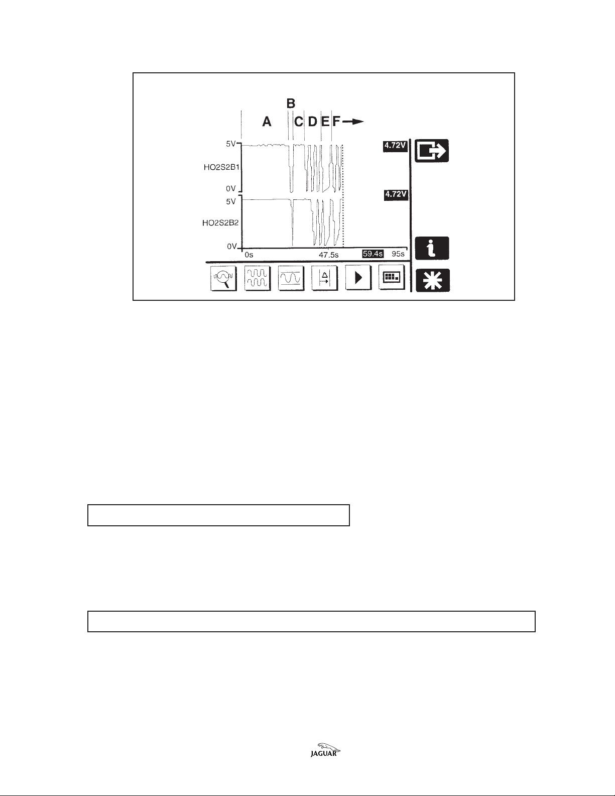
to allow the system diagnostic check to occur. This check also takes approximately
5-10 seconds. See Illustration 1, sample of PDU trace. This complete cycle takes
place each time the engine is started.
cc
harhar
t.t.
c
har
t.
cc
harhar
t.t.
Bulletin Number 17-10 Date of issue 8/97 Page 1 of 5
This is the re-test referThis is the re-test refer
This is the re-test refer
This is the re-test referThis is the re-test refer
red to in the flowred to in the flow
red to in the flow
red to in the flowred to in the flow
PDU PDU
PDU
PDU PDU
TRATRA
TRA
TRATRA
CE SHOCE SHO
CE SHO
CE SHOCE SHO
WING CORRECT WING CORRECT
WING CORRECT
WING CORRECT WING CORRECT
AIR PUMP OPERAAIR PUMP OPERA
AIR PUMP OPERA
AIR PUMP OPERAAIR PUMP OPERA
ILLUSTRA TION 1
TIONTION
TION
TIONTION
JSI-3154
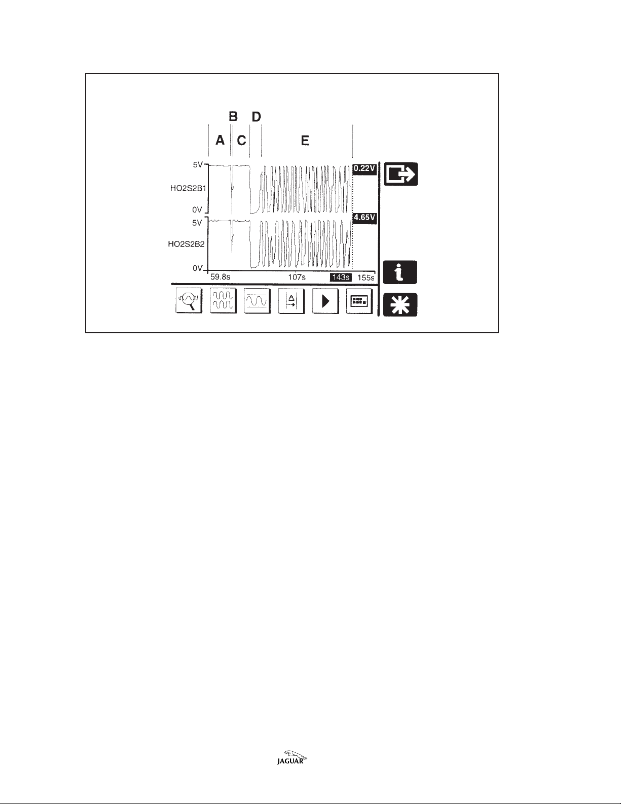
Zone ‘A’ shows the initial operation of the air pump (air flow causes lean reading).
Zone ‘B’ shows the pump switched off, prior to the diagnostic test (stopping air
flow causes rich reading).
Zone ‘C’ shows the pump operating during the diagnostic test cycle.
Zone ‘D’ shows the pump switched off when the test is complete.
Zone ‘E’ shows the lambda voltage switching under normal lambda operation.
Page 2 of 5 Date of issue 8/97 Bulletin Number 17-10
PDU PDU
TRATRA
PDU
PDU PDU
TRA
TRATRA
CE SHOCE SHO
CE SHO
CE SHOCE SHO
WING INADEQWING INADEQ
WING INADEQ
WING INADEQWING INADEQ
UAUA
TE TE
AIR FLAIR FL
UA
TE
UAUA
TE TE
ILLUSTRA TION 2
AIR FL
AIR FLAIR FL
OO
O
OO
WW
W
WW
JSI-3155
Illustration 2 shows a PDU trace where there is inadequate air flow from the air
pump.
Zone ‘A’ shows the initial operation of the air pump (air flow causes lean reading).
Zone ‘B’ shows the pump switched off, prior to the diagnostic test (stopping air
flow causes rich reading).
Zone ‘C’ shows the pump operating during the diagnostic test cycle.
Zone ‘D’ shows the lambda voltage switching to normal feedback, as there is
insufficient air flow to sustain the voltage at 5v.
Zone ‘E’ shows the air pump switched off at the end of the diagnostic cycle.
Zone ‘F’ shows the lambda voltage switching under normal lambda operation.
Check outlet port of pump for strong air flow
The air flow from the air pump should be strong enough to almost prevent the
palm of the hand from staying pressed against the outlet port of the pump. In
situations where DTC P0411 is flagged, the air flow from the pump outlet will be
very weak.
Check ports of pump for signs of overheating or excessive build-up of carbon.
This check should be performed when the voltage trace is correct, in case of
intermittent operation of the pump. Look for excessive buildup of carbon on the
outlet port, and check if the foam filter in the inlet port has melted or is out of
position. In such cases, replace the outlet check valve also.
Bulletin Number 17-10 Date of issue 8/97 Page 3 of 5

Follow electrical diagrams in XJS Electrical Guide
If the AIR pump does not operate as described on page 1, refer to Fig. 25 of the
XJS Range 1995/6 Electrical Guide.
Is “bleed nipple” hose fitted?
On vehicles from VIN 194775 - 199153, check that the hose between the air pump
and check valve is the type incorporating an anti-vacuum bleed nipple, as
introduced in production from VIN 199154 (refer to Technical Bulletin 18-47
Amended 4/95.) If not, install the appropriate later-design hose.
PP
ARAR
TS INFORMATS INFORMA
P
AR
TS INFORMA
PP
ARAR
TS INFORMATS INFORMA
DESCRIPTIONDESCRIPTION
DESCRIPTION
DESCRIPTIONDESCRIPTION
Air Injection Pump LHE 1545A C 1
Check V alve EBC 1 1499 1
Hose, pump to check valve, Normally aspirated NBC 4798AA 1
WW
ARRANARRAN
W
ARRAN
WW
ARRANARRAN
FF
AA
ULUL
F
A
UL
FF
AA
ULUL
CODECODE
CODE
CODECODE
BG BB ** 17.25.07 Air pump - renew 0.60 hours
TY INFORMATY INFORMA
TY INFORMA
TY INFORMATY INFORMA
TT
T
TT
TION:TION:
TION:
TION:TION:
PP
ARAR
T NUMBERT NUMBER
P
AR
T NUMBER
PP
ARAR
T NUMBERT NUMBER
TION:TION:
TION:
TION:TION:
R.OR.O
..
R.O
.
R.OR.O
..
NUMBERNUMBER
NUMBER
NUMBERNUMBER
17.25.21 Check valve - renew 0.20 hours
86.99.01 Read and clear DTCs. 0.50 hours
DESCRIPTIONDESCRIPTION
DESCRIPTION
DESCRIPTIONDESCRIPTION
(including diagnostic time)
Fill out Form S93.
TIMETIME
TIME
TIMETIME
ALLALL
ALL
ALLALL
OO
O
OO
WW
W
WW
ANCEANCE
ANCE
ANCEANCE
QTYQTY
QTY
QTYQTY
Page 4 of 5 Date of issue 8/97 Bulletin Number 17-10
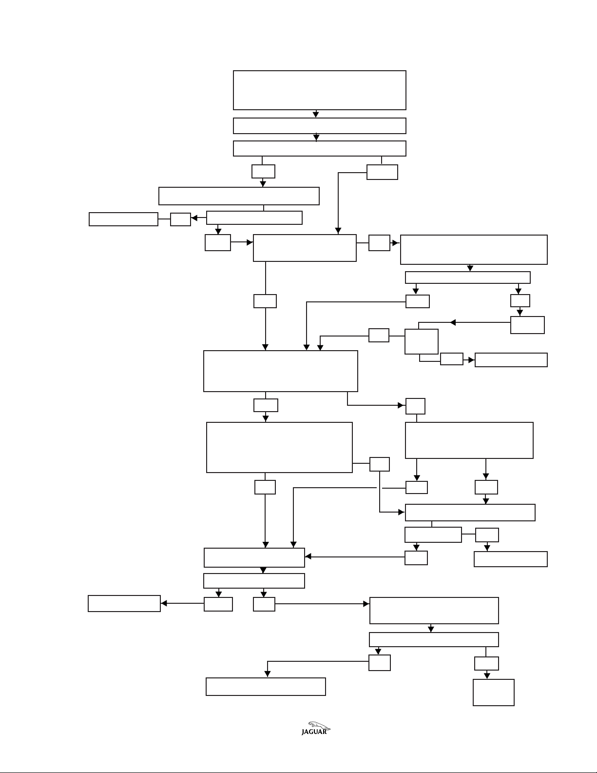
DIADIA
GNOSGNOS
DIA
GNOS
DIADIA
GNOSGNOS
With the engine at normal operating
temperature, connect the PDU and
read DTC P0411. Fill out form S93.
Is ‘bleed nipple’ hose installed?
NO YES
Install ‘bleed nipple’ hose. Retest
Return vehicle NO Defect still present?
YES Does AIR pump NO Refer to electrical diagrams in
operate? XJS Electrical Guide
YES YES NO
In PDU Datalogger, run engine YES Return vehicle
while monitoring HO2S voltage.
Is voltage trace correct?
TIC FLTIC FL
OO
TIC FL
TIC FLTIC FL
Clear DTC.
WCHARWCHAR
O
WCHAR
OO
WCHARWCHAR
TT
T
TT
NO Retest
OK?
Circuit OK?
Repair
YES NO
Check ports of pump for signs Check outlet port of pump
of overheating or excessive for strong air flow.
buildup of carbon. Strong air flow?
Pump OK? NO
YES YES NO
Replace pump
Retest OK? YES
Replace c heck valve NO Return vehicle
Retest OK?
Return vehicle YES NO Check pipe for blockage.
Clear/replace as necessary .
Retest, OK?
NO YES
Contact Technical Hotline Return
vehicle
Bulletin Number 17-10 Date of issue 8/97 Page 5 of 5

TECHNICAL BULLETIN
Throttle Difficult to Open on Cold Engine
– Normally Aspirated Engines –
Modify Crankcase Breather System
MODEL 1995-96 MY XJS
VIN 194775-226643
ISSUE:ISSUE:
ISSUE:
ISSUE:ISSUE:
On some 4.0L XJS vehicles, owners may experience slight difficulty in opening
the throttle from the closed position after the vehicle has been sitting for some
time. Under certain circumstances, oil mist from the crankcase may collect and
harden on the throttle body and plate when the engine is cold, where it may cause
this condition.
AA
CTION:CTION:
A
CTION:
AA
CTION:CTION:
Perform the following modification to include an oil separator in the crankcase
ventilation system, along with cleaning operations on the throttle body unit,
when there is a history of customer complaint of the condition described above.
DATE 12/98
17-11
onlyonly
only
onlyonly
MODIFICATION PROCEDURE
1. Open the hood and install fender covers.
2. Disconnect the multiple connectors from the intake air temperature sensor
(IATS) and from the mass air flow sensor (MAFS).
3. Disconnect the convoluted hose from the throttle body.
4. Remove the nut that secures the rubber mounting bobbin to the induction
elbow; release the air cleaner to MAFS retaining clips and remove the MAFS/
induction elbow assembly to provide further access.
5. Unscrew by ONE turn the throttle stop adjustment screw, so that no air gap
exists on either side of the throttle plate. It will be necessary to shorten a
standard hexagon wrench (Allen wrench) for access to this screw.
6. Hold the throttle closed and remove the screws that retain the throttle plate to
the shaft.
7. Note the direction of assembly to assist during reassembly and then remove
the throttle plate after opening the throttle shaft.
Note: Note:
Note: During the above operation, ensure that the shaft is not
Note: Note:
pulled out of the potentiometer. If this occurs, removal of the
potentiometer will be required to permit reassembly.
8. Gently return the shaft to the ‘closed’ position.
9. Use a suitable solvent and shop towel to carefully remove all residual
Bulletin Number 17-11 Date of issue 12/98 Page 1 of 5
contaminants from the throttle plate and throttle body air passage. Use care
not to allow excess solvent to run down the throttle shaft or enter the intake
manifold. Use a mirror to assist in checking that all deposits have been
removed. Dry off any residual solvent/deposits.
10. Using care not to disengage the throttle shaft from the potentiometer below,
and noting the correct orientation, reinstall the throttle plate in the shaft.
Apply thread locking compound to the threads of the securing screws and
start, but do not fully tighten, the two securing screws.
11. Check with a mirror that the throttle plate is centered with the throttle fully
closed, as the retaining screws are tightened enough to grip the plate. Open
the throttle against spring pressure, then allow it to snap closed - this will help
center the throttle plate on the shaft and to the venturi. Repeat if necessary,
then fully tighten the throttle plate retaining screws.
Caution:Caution:
Caution: No specific torque setting is available for the throttle
Caution:Caution:
plate screws. Tighten them appropriately for brass screws of this
size.
12. Check that the locking patch of the throttle stop screw is still effective.
Sufficient drag must remain to ensure that any setting will not be disturbed by
vibration, otherwise apply fresh locking compound. Adjust the screw to open
the throttle plate until a narrow 0.002 inch feeler blade can fit between the
throttle plate and the venturi.
13. Remove the screws that retain the fuel rail cover and remove the cover.
14. Loosen the clamps and remove the breather hose from the engine.
MODIFYING EXISMODIFYING EXIS
MODIFYING EXIS
MODIFYING EXISMODIFYING EXIS
CUT HERECUT HERE
CUT HERE
CUT HERECUT HERE
DETDET
AIL FOR CUTTINGAIL FOR CUTTING
DET
AIL FOR CUTTING
DETDET
AIL FOR CUTTINGAIL FOR CUTTING
EXISEXIS
TING BREATING BREA
EXIS
TING BREA
EXISEXIS
TING BREATING BREA
TING BREATING BREA
TING BREA
TING BREATING BREA
11
6 MM (5/8 INCH)6 MM (5/8 INCH)
1
6 MM (5/8 INCH)
11
6 MM (5/8 INCH)6 MM (5/8 INCH)
THER HOSETHER HOSE
THER HOSE
THER HOSETHER HOSE
THER HOSETHER HOSE
THER HOSE
THER HOSETHER HOSE
22 MM (7/8 INCH)22 MM (7/8 INCH)
A
22 MM (7/8 INCH)
22 MM (7/8 INCH)22 MM (7/8 INCH)
B
ILLUSTRATION 1
LOCALOCA
TION FOR RESTION FOR RES
LOCA
TION FOR RES
LOCALOCA
TION FOR RESTION FOR RES
TRICTERTRICTER
TRICTER
TRICTERTRICTER
JSI.3438
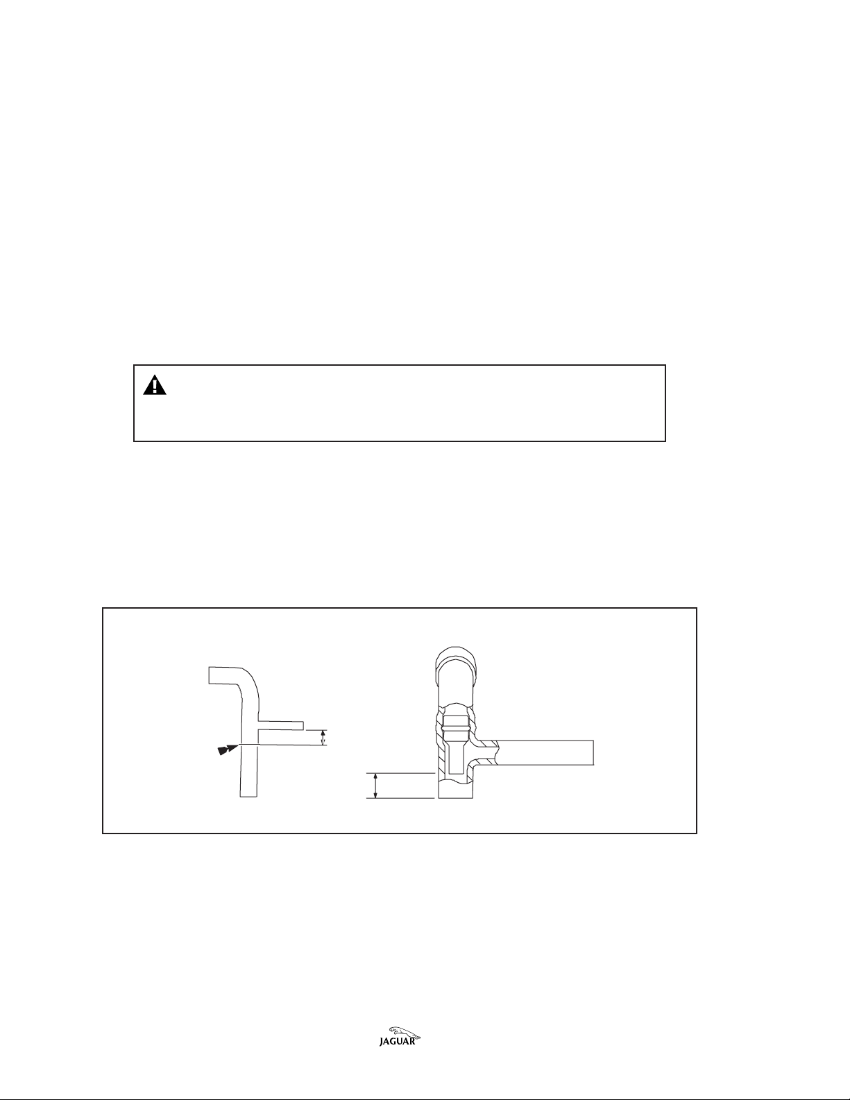
15. Cut the existing breather hose as shown in Illustration 1. Make sure that a
clean cut is made, maintaining the 22 mm (7/8 inch) dimension consistently.
16. Insert the larger diameter of a restricter (Part No. NNB 3956AA ) into the cut
upper end of the hose. Push the restricter fully into the hose, until the lower
end is 16 mm (5/8 inch) from the cut end, as in Illustration 1.
Page 2 of 5 Date of issue 12/98 Bulletin Number 17-11
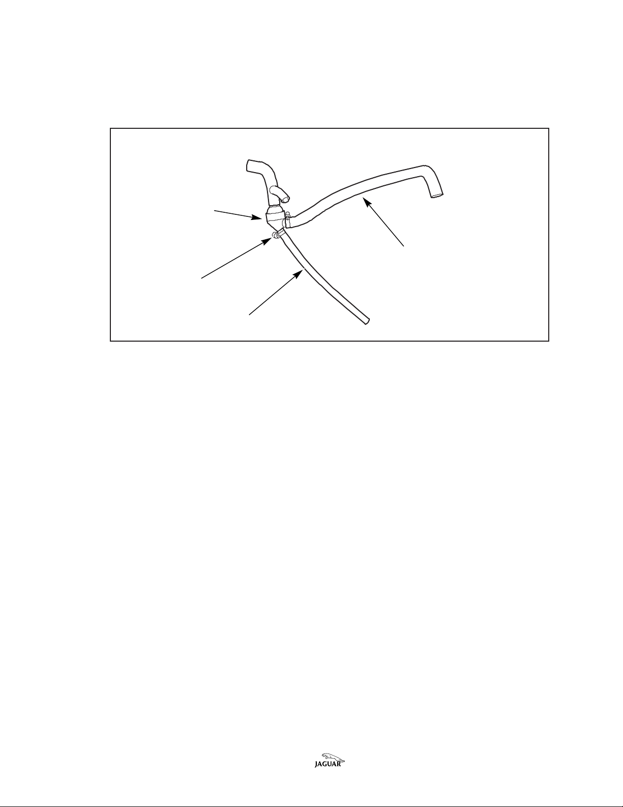
17. Install a worm drive hose clamp (Part No. JHC 200401) and connect the upper
portion of the breather hose to the top stub of the oil separator (Part No. NNB
2102AA), as in Illustration 2.
ASSEMBLASSEMBL
ASSEMBL
ASSEMBLASSEMBL
VV
V
VV
Y OF HOSES Y OF HOSES
Y OF HOSES
Y OF HOSES Y OF HOSES
APOR SEPAPOR SEP
APOR SEP
APOR SEPAPOR SEP
HOSE CLAMPHOSE CLAMP
HOSE CLAMP
HOSE CLAMPHOSE CLAMP
ARAARA
ARA
ARAARA
TT
O OIL SEPO OIL SEP
T
O OIL SEP
TT
O OIL SEPO OIL SEP
TT
OROR
T
OR
TT
OROR
DRAIN HOSEDRAIN HOSE
DRAIN HOSE
DRAIN HOSEDRAIN HOSE
ARAARA
TT
OROR
ARA
T
OR
ARAARA
TT
OROR
ILLUSTRATION 2
EXISEXIS
TING HOSETING HOSE
EXIS
TING HOSE
EXISEXIS
TING HOSETING HOSE
JSI.3432
18. Installing a worm drive hose clamp (JHC 200401) to the lower portion of the
existing breather tube, connect it to the side stub of the oil separator, and with
a hose clamp (JHC 200101) install the drain hose (NNB 5961AA) to the lower
stub of the oil separator, as in Illustration 2.
It is imporIt is impor
It is impor
It is imporIt is impor
‘‘
engineengine
‘
engine
‘‘
engineengine
tant that the worm housing of the hose clamp is installed facing thetant that the worm housing of the hose clamp is installed facing the
tant that the worm housing of the hose clamp is installed facing the
tant that the worm housing of the hose clamp is installed facing thetant that the worm housing of the hose clamp is installed facing the
’ side of the hose and oil separator’ side of the hose and oil separator
’ side of the hose and oil separator
’ side of the hose and oil separator’ side of the hose and oil separator
..
.
..
19. Tighten the hose clamps with the hoses positioned as in Illustration 2.
20. Remove the dipstick from the dipstick tube. Wipe it clean and place it aside in
a clean location until reinstalled later.
21. Remove the retaining screw at the support bracket and remove the existing
dip stick tube from the engine. Remove the existing ‘P’ clip for reuse before
discarding the existing dip stick tube.
22. Ensure that the rubber sealing tube for the dip stick tube remains on the
engine.
23. Transfer the ‘P’ clip to the replacement dip stick tube (NNB 3908AA), install the
dip stick tube on the engine (ensuring that it is fully seated). Reinstall the
retaining screw on the tube and bracket.
Bulletin Number 17-11 Date of issue 12/98 Page 3 of 5

FEEDING BREAFEEDING BREA
FEEDING BREA
FEEDING BREAFEEDING BREA
THER THER
TUBE UNDER FUEL RAILTUBE UNDER FUEL RAIL
THER
TUBE UNDER FUEL RAIL
THER THER
TUBE UNDER FUEL RAILTUBE UNDER FUEL RAIL
JSI.3433
BREABREA
BREA
BREABREA
THER HOSETHER HOSE
THER HOSE
THER HOSETHER HOSE
ILLUSTRATION 3
24. As shown in Illustration 3, route the end of the longer breather hose (attached
to the side stub of the new oil separator) under the fuel rail. When part-way
under the fuel rail, route the thinner drain tube (attached to the bottom stub of
the oil separator) between the runners of the intake manifold so that it can
eventually be connected to the new dip stick tube.
HOSE INSHOSE INS
HOSE INS
HOSE INSHOSE INS
TT
ALLED ALLED
T
ALLED
TT
ALLED ALLED
BREABREA
BREA
BREABREA
WITH WITH
VV
WITH
V
WITH WITH
VV
THER HOSETHER HOSE
THER HOSE
THER HOSETHER HOSE
APOR SEPAPOR SEP
APOR SEP
APOR SEPAPOR SEP
ARAARA
ARA
ARAARA
TT
T
TT
OROR
OR
OROR
JSI.3431
VV
APOR SEPAPOR SEP
V
APOR SEP
VV
APOR SEPAPOR SEP
ARAARA
ARA
ARAARA
TT
OROR
T
OR
TT
OROR
ILLUSTRATION 4
25. Continue to align the breather hose assembly until the upper breather hose
can be reconnected to the stub pipe on the camshaft cover and the original
hose clamp tightened, as in Illustration 4.
26. Install the drain hose on the side connection on the replacement dip stick
tube, installing a worm drive hose clamp (JHC 200101) over the hose, and
tightening the clamp once the hose is fully connected and free of any kinks.
27. Check that the dip stick is clean and reinstall it.
28. Reinstall the MAFS/induction elbow assembly and reconnect the multiplugs.
29. Connect the lower end of the breather hose to the stub on the induction elbow
and tighten the hose clamp.
Page 4 of 5 Date of issue 12/98 Bulletin Number 17-11

30. Reconnect the side hose above the oil separator to its original stub pipe and
tighten the hose clamp.
31. At the PDU base station, load JTP 626/4. Select Diagnostics, Vehicle Setup,
then select Engine Setup. Connect the PDU to the vehicle. Under Engine
Setup, select Throttle Position Sensor Adaption Test. Answer YES to the
question, “Has a new throttle position sensor been fitted?” After the test
passes, the idle speed will be correct.
32. Remove the fender covers and close the hood.
PP
ARAR
TS INFORMATS INFORMA
P
AR
TS INFORMA
PP
ARAR
TS INFORMATS INFORMA
TION:TION:
TION:
TION:TION:
The following should be ordered from Jaguar Parts Operations:
DESCRIPTIONDESCRIPTION
DESCRIPTION
DESCRIPTIONDESCRIPTION
Breather Kit JLM 20709 1
Screw, throttle plate retaining JLM 20936 *
* only needed if lost or damaged
CONTENTS LIST - BREATHER KIT JLM 20709 (For Information Only)
DESCRIPTIONDESCRIPTION
DESCRIPTION
DESCRIPTIONDESCRIPTION
Breather-Oil Separator NNB 2102AA 1
Restricter - Part Load Breather NNB 3956AA 1
Tube - Dipstick NNB 3908AA 1
Hose - Oil Drain NNB 5961AA 1
Clamp, Hose, Worm Drive JHC 200101 2
Clamp, Hose, Worm Drive JHC 200401 2
WW
ARRANARRAN
W
ARRAN
WW
ARRANARRAN
FF
AA
ULUL
F
A
UL
FF
AA
ULUL
CODECODE
CODE
CODECODE
CD KF 69 17.91.33 Engine Breather System 0.85 hrs.
TY INFORMATY INFORMA
TY INFORMA
TY INFORMATY INFORMA
TT
T
TT
TION:TION:
TION:
TION:TION:
R.OR.O
..
R.O
.
R.OR.O
..
NUMBERNUMBER
NUMBER
NUMBERNUMBER
DESCRIPTIONDESCRIPTION
DESCRIPTION
DESCRIPTIONDESCRIPTION
Modification (includes throttle position
adaption test)
PP
ARAR
T NUMBERT NUMBER
P
AR
T NUMBER
PP
ARAR
T NUMBERT NUMBER
PP
ARAR
T NOT NO
P
AR
T NO
PP
ARAR
T NOT NO
QTYQTY
QTY
QTYQTY
..
.
..
QTYQTY
QTY
QTYQTY
TIMETIME
TIME
TIMETIME
ALLALL
ALL
ALLALL
OO
O
OO
WW
ANCEANCE
W
ANCE
WW
ANCEANCE
Bulletin Number 17-11 Date of issue 12/98 Page 5 of 5
TECHNICAL BULLETIN
Recall T493 - 1995 MY/Recall
R493 - 1996 MY
– AJ16 EGR System –
Replace PROMs and EGR Valve
MODEL 1995-96 MY XJS 4.0L
VIN 194775-226645
Remove and destroy Bulletin 17-12, amended 11/01.
Replace with this Bulletin.
This Recall supersedes Service Action S483.
Note:Note:
Note: In January 2002 Jaguar advised you that the above recall
Note:Note:
action required on 1995 MY vehicles was temporarily suspended
due to unforeseen problems with one of the components
associated with this recall. Jaguar had requested that dealers
cease conducting further actions on 1995 MY vehicles until the
problem with the affected component had been resolved.
JJ
aguar is now pleased to inform you that the issue with theaguar is now pleased to inform you that the issue with the
J
aguar is now pleased to inform you that the issue with the
JJ
aguar is now pleased to inform you that the issue with theaguar is now pleased to inform you that the issue with the
PROMs has been resolved, and that JPROMs has been resolved, and that J
PROMs has been resolved, and that J
PROMs has been resolved, and that JPROMs has been resolved, and that J
contacting ownercontacting owner
contacting owner
contacting ownercontacting owner
have the repair performed.have the repair performed.
have the repair performed.
have the repair performed.have the repair performed.
s requesting that they contact their dealer tos requesting that they contact their dealer to
s requesting that they contact their dealer to
s requesting that they contact their dealer tos requesting that they contact their dealer to
aguar once agaguar once ag
aguar once ag
aguar once agaguar once ag
DATE 11/01
ain will beain will be
ain will be
ain will beain will be
17-12
Amended
08/02
This version of the recall bulletin has a revised part number for
the 1995 MY vehicle. Additional Warranty Information has been
added for those 1995 MY vehicles previously re-worked under
this Recall Action. Please destroy all previous versions of Recall
Action Bulletin R493 and replace it with this version.
Please note that the Recall number for 1995 MY vehicles is now
T493, R493 will continue to be used for 1996 MY vehicles.
ISSUE:ISSUE:
ISSUE:
ISSUE:ISSUE:
Since the introduction of the AJ16 engine Jaguar has seen a high rate of
replacement of EGR valves following illumination of the malfunction indicator
lamp (MIL). This is understood to be a result of accumulated contamination within
the EGR valve that can produce possible drivability issues such as rough idle,
hesitation, and difficult starting.
Following consultation with the US En vironmental Protection Agency (EPA) Jaguar
has decided to recall all vehicles equipped with this engine and carry out a
number of modifications including the introduction of a cleaning cycle to the EGR
valve. The following actions apply to all vehicles within the above VIN ranges.
• Replace PROMs within Engine Control Module (ECM). J aguar Cars has
upgraded the PROMs within the ECM to provide a cleaning cycle of the EGR
system.
Bulletin Number 17-12 Amended 08/02 Date of issue 11/0 1 Page 1 of 16

• Replace EGR valve and gasket, to ensure that it is free from contamination.
• Replace throttle return spring. Some vehicles may experience customer
complaints of high idle speeds.
Jaguar Cars is writing to all owners of the above vehicles (in timed mailings) to
advise them to take their vehicles into their local dealer to have the above
modifications made.
This recall will supersede Service Action S483, S675, and S676, no further claims
for these Service Actions will be accepted.
AA
CTION:CTION:
A
CTION:
AA
CTION:CTION:
Refer to the following charts to determine the appropriate course of action.
RAEYLEDOMRAEYLEDOM
RAEYLEDOMRAEYLEDOMTNENOPMOCTNENOPMOC
RAEYLEDOM
demrofrepylsuoiverpllaceR-YM59
evlaVRGEX
TNENOPMOCTNENOPMOCSJXSJX
TNENOPMOC
teksaGevlaVRGEX
deriuqeRsAtloBevlaVRGEX
SJXSJX
SJX
rehtruFoN
tnemecalpeRgnirpSelttorhT
tnemecalpeRMORPEX
demrofrepylsuoiverpllaceR-YM69
noitcA
deriuqeR
rehtruFoN
noitcA
deriuqeR
Page 2 of 16 Date of issue 11/01 Bulletin Number 17-12 Amended 08/02

llaceR-YM59tonton
tontondemrofrepylsuoiverp
ton
RAEYLEDOMRAEYLEDOM
RAEYLEDOMRAEYLEDOMTNENOPMOCTNENOPMOC
RAEYLEDOM
TNENOPMOCTNENOPMOCSJXSJX
TNENOPMOC
evlaVRGEX
teksaGevlaVRGEX
SJXSJX
SJX
llaceR-YM69tonton
tontondemrofrepylsuoiverp
ton
tloBevlaVRGEderiuqeRsAderiuqeRsA
tnemecalpeRMORPEX
evlaVRGEX
teksaGevlaVRGEX
tloBevlaVRGEderiuqeRsAderiuqeRsA
tnemecalpeRMORPEX
deriuqeRsAderiuqeRsAX
deriuqeRsA
tnemecalpeRgnirpSelttorhTX
deriuqeRsAderiuqeRsAX
deriuqeRsA
tnemecalpeRgnirpSelttorhTX
Bulletin Number 17-12 Amended 08/02 Date of issue 11/0 1 Page 3 of 16

Note:Note:
Note: In the case of customer brings to the dealer a vehicle that
Note:Note:
exhibits a drivability concern that the recall action does not
eradicate, normal diagnostic procedures can be followed as
necessary to determine the root cause. The completion of any
subsequent repairs are subject to normal New Car Warranty or
Select Edition Warranty, or customer pay authorization as
appropriate.
Remove the ECM from the vehicle by the following procedure.
1. Connect the WDS to the vehicle’s data link connector.
2. Record any diagnostic trouble codes stored in the ECM, then clear them from
the system.
3. Turn the ignition switch to ‘off’, wait 20 seconds before continuing with this
procedure.
4. Note customer settings such as radio stations.
5. Open the luggage compartment, remove the cover from the battery and
disconnect the battery ground cable.
REMOVING ECM
1. Open the right hand door and remove the carpet from the foot well.
2. Remove the ECM cover insulation pad.
3. Remove the securing nuts and remove the cover from the ECM.
4. Remove the ECM from its mounting, disconnect both harness connectors and
remove the ECM from the vehicle.
5. Mark the VIN on the side of the ECM to prevent confusion when more than
one ECM is being modified.
ISSUE 1 - REPLACING PROM
1. Check that the ‘anti-back out’ plate on the face of each harness connector is
still in place after disconnecting the connector.
Note: Note:
Note: In the event of the anti-back out plate becoming loose or
Note: Note:
detached, secure it to the face of the connector, pressing it firmly
in place.
Page 4 of 16 Date of issue 11/01 Bulletin Number 17-12 Amended 08/02
ANAN
AN
ANAN
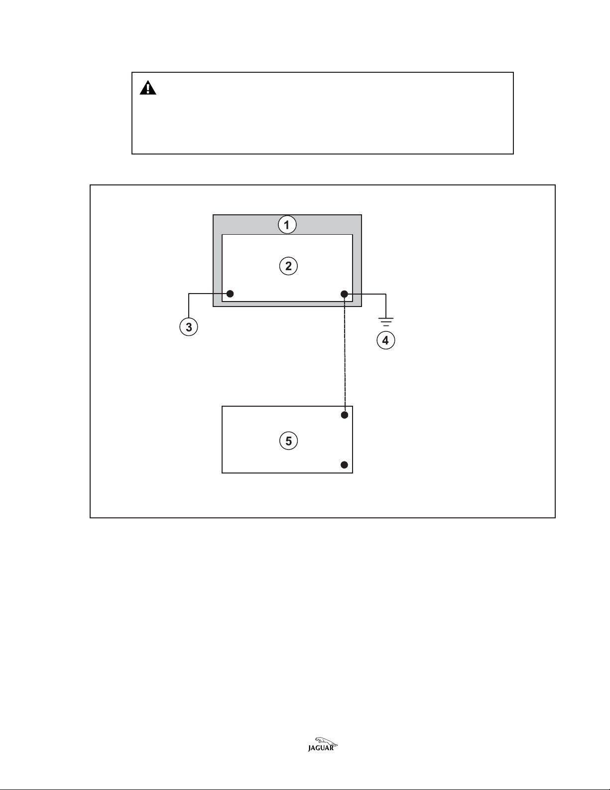
Caution:Caution:
Caution: Perform the following operations at an antistatic
Caution:Caution:
workstation (previously supplied) while wearing a grounding
wrist-strap (Illustration 1). Additional work mats can be sourced
locally, such as Radio Shack cat. no. 910-3780.
TI-STI-S
TT
AA
TIC TIC
WW
ORKSORKS
TT
AA
TI-S
TI-STI-S
T
A
TIC
W
TIC TIC
ORKS
WW
ORKSORKS
TT
AA
T
TT
TIONTION
A
TION
AA
TIONTION
1 – WORK BENCH
2 – WORK MAT
3 – WRIST STRAP CONNECTION
4 – GROUND CONNECTION
5 – FOOT MAT
JSI 2663
ILLUSTRATION 1
2. Place the ECM on the anti-static work mat, with one flat face to the mat.
Looking towards the two connectors, the red connector should be to the
upper right, the blac k connector to the lower left.
3. Note the orientation of the top cover with its mounting lugs, relative to the
ECM casing. Mark both the cover and casing, using a felt-tip marker pen, to
assist when reassembling.
4. Remove the four retaining screws of the top ECM cover (i.e. the cover
adjacent to the red connector) using a Torx 20 anti-tamper type bit. Remove
the cover.
Bulletin Number 17-12 Amended 08/02 Date of issue 11/0 1 Page 5 of 16
LL
OCAOCA
TION OF PROMS IN ECMTION OF PROMS IN ECM
L
OCA
TION OF PROMS IN ECM
LL
OCAOCA
TION OF PROMS IN ECMTION OF PROMS IN ECM
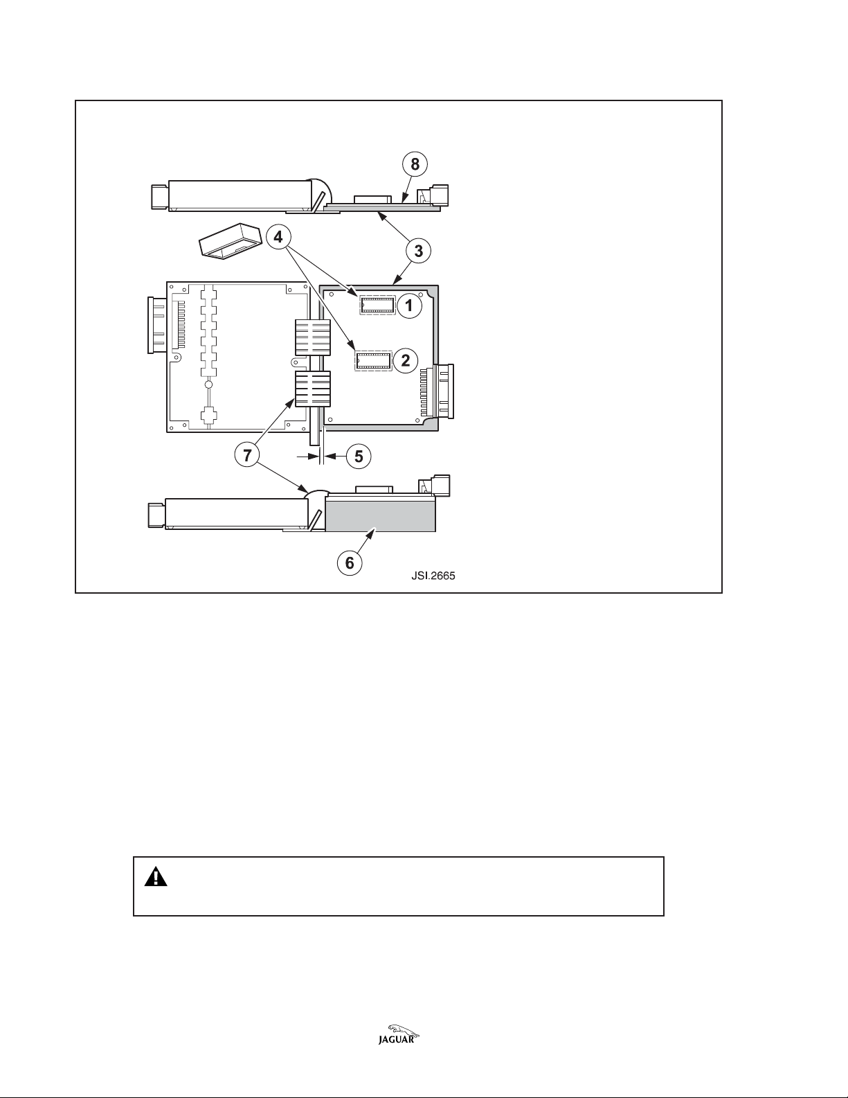
1 – 28 PIN PROM1 – 28 PIN PROM
1 – 28 PIN PROM
1 – 28 PIN PROM1 – 28 PIN PROM
2 – 32 PIN PROM2 – 32 PIN PROM
2 – 32 PIN PROM
2 – 32 PIN PROM2 – 32 PIN PROM
3 – ECM CO3 – ECM CO
3 – ECM CO
3 – ECM CO3 – ECM CO
4 – PROM CO4 – PROM CO
4 – PROM CO
4 – PROM CO4 – PROM CO
5 – CLEARANCE SP5 – CLEARANCE SP
5 – CLEARANCE SP
5 – CLEARANCE SP5 – CLEARANCE SP
6 – 6 –
WOOD SUPPORWOOD SUPPOR
6 –
WOOD SUPPOR
6 – 6 –
WOOD SUPPORWOOD SUPPOR
7 – RIBBON CABLES7 – RIBBON CABLES
7 – RIBBON CABLES
7 – RIBBON CABLES7 – RIBBON CABLES
8 - PRIN8 - PRIN
8 - PRIN
8 - PRIN8 - PRIN
VERVER
VER
VERVER
VERSVERS
VERS
VERSVERS
TED CIRCUIT BOTED CIRCUIT BO
TED CIRCUIT BO
TED CIRCUIT BOTED CIRCUIT BO
AA
CECE
A
CE
AA
CECE
TT
T
TT
ARDARD
ARD
ARDARD
ILLUSTRATION 2
5. Remove the seven retaining screws of the printed circuit board (8, Illustration
2). Fold the printed circuit board away from the body of the ECM unit and
support it on a block of wood (6, Illustration 2) so that no strain is placed on
the ribbon connectors (7, Illustration 2). Allow a clearance space (5,
Illustration 2) so that no damage can occur from contact with the mounting
brackets.
6. The modification kit contains two microc hips, one each of the 28-pin (1,
Illustration 2) and 32-pin (2, Illustration 2) design.
7. Remove the covers (4, Illustration 2) from the microchips on the printed circuit
board. Remove each cover by applying a side-to-side rocking action, gripping
the cover lightly with combination pliers midway along each long side.
Caution: Caution:
Caution: Do not touc h the printed circuit board with the
Caution: Caution:
pliers, or mark the surface of the printed circuit board.
Page 6 of 16 Date of issue 11/01 Bulletin Number 17-12 Amended 08/02

EXAMPLE OF CHIP REMOEXAMPLE OF CHIP REMO
EXAMPLE OF CHIP REMO
EXAMPLE OF CHIP REMOEXAMPLE OF CHIP REMO
VV
V
VV
AL AL
AL
AL AL
TT
OOLOOL
T
OOL
TT
OOLOOL
ILLUSTRATION 3
8. Remove the PROM microchips from the printed circuit board using a suitable
proprietary removal/reinstallation tool (Illustrations 3 & 4).
USE OF USE OF
USE OF
USE OF USE OF
TYPICAL CHIP REMOTYPICAL CHIP REMO
TYPICAL CHIP REMO
TYPICAL CHIP REMOTYPICAL CHIP REMO
VV
AL AL
TT
OOLOOL
V
AL
T
OOL
VV
AL AL
TT
OOLOOL
ILLUSTRATION 4
Bulletin Number 17-12 Amended 08/02 Date of issue 11/0 1 Page 7 of 16
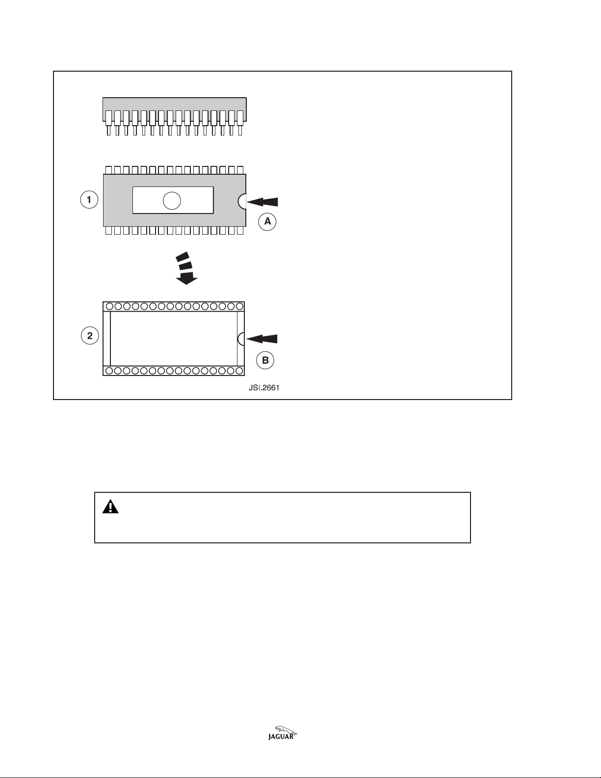
MICROCHIP ORIENMICROCHIP ORIEN
MICROCHIP ORIEN
MICROCHIP ORIENMICROCHIP ORIEN
TT
T
TT
AA
TIONTION
A
TION
AA
TIONTION
1 – O1 – O
VERHEAD VERHEAD
1 – O
VERHEAD
1 – O1 – O
VERHEAD VERHEAD
2 – O2 – O
VERHEAD VERHEAD
2 – O
VERHEAD
2 – O2 – O
VERHEAD VERHEAD
CIRCUIT BOCIRCUIT BO
CIRCUIT BO
CIRCUIT BOCIRCUIT BO
3 – IDEN3 – IDEN
3 – IDEN
3
3 – IDEN3 – IDEN
A – ‘HALF MOON’ CUTA – ‘HALF MOON’ CUT
A – ‘HALF MOON’ CUT
A – ‘HALF MOON’ CUTA – ‘HALF MOON’ CUT
B – ‘HALF MOON’ CUTB – ‘HALF MOON’ CUT
B – ‘HALF MOON’ CUT
B – ‘HALF MOON’ CUTB – ‘HALF MOON’ CUT
VIEW OF MICROCHIPVIEW OF MICROCHIP
VIEW OF MICROCHIP
VIEW OF MICROCHIPVIEW OF MICROCHIP
VIEW OF SOCKET ON PRINVIEW OF SOCKET ON PRIN
VIEW OF SOCKET ON PRIN
VIEW OF SOCKET ON PRINVIEW OF SOCKET ON PRIN
ARDARD
ARD
ARDARD
TIFICATIFICA
TION OF MICROCHIPTION OF MICROCHIP
TIFICA
TION OF MICROCHIP
TIFICATIFICA
TION OF MICROCHIPTION OF MICROCHIP
-OUT ON MICROCHIP-OUT ON MICROCHIP
-OUT ON MICROCHIP
-OUT ON MICROCHIP-OUT ON MICROCHIP
-OUT ON SOCKET-OUT ON SOCKET
-OUT ON SOCKET
-OUT ON SOCKET-OUT ON SOCKET
TEDTED
TED
TEDTED
ILLUSTRATION 5
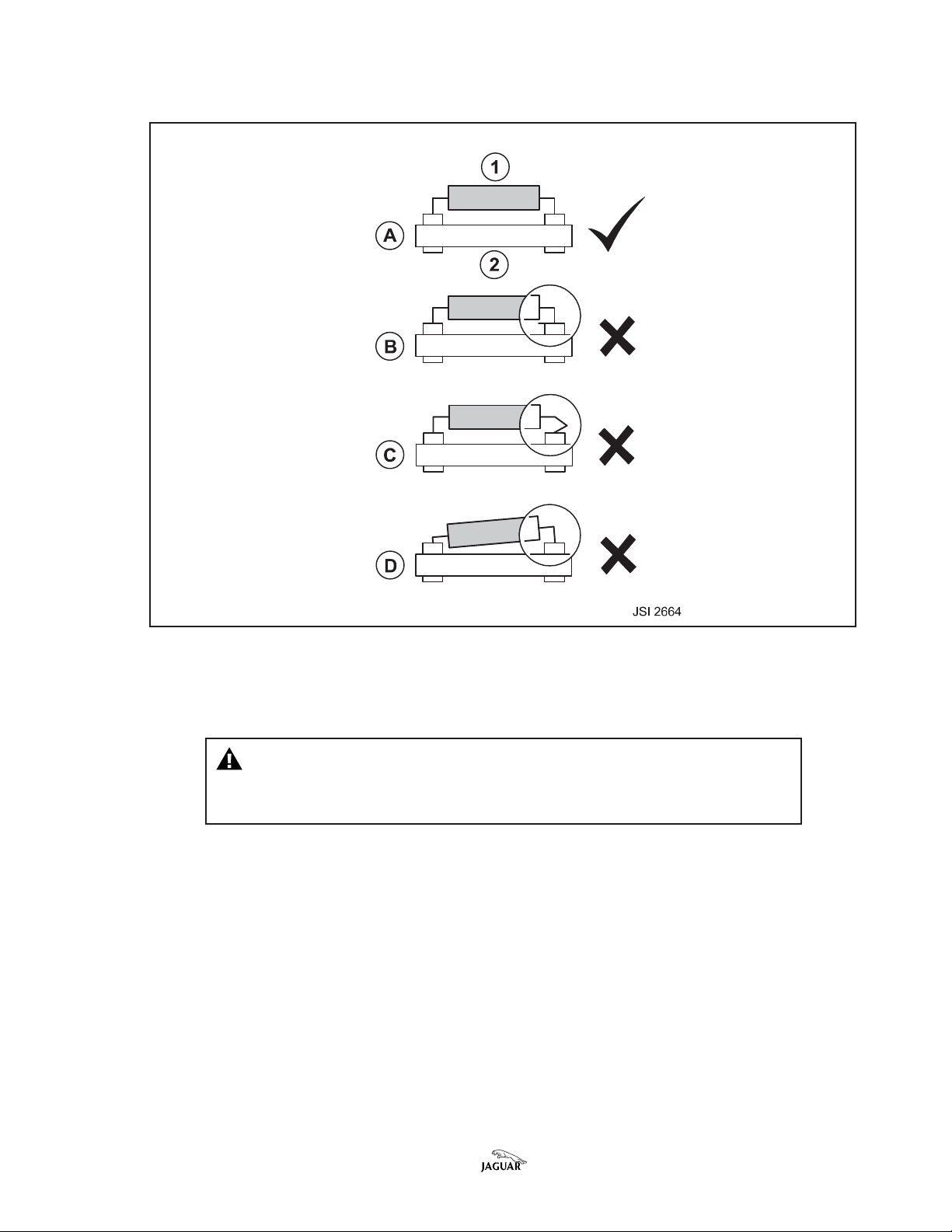
9. When inserting the replacement PROM microchips, identify the ‘half moon’
cutouts in both the microchip and the socket on the printed circuit board
(Illustration 5).
Caution:Caution:
Caution: Correct orientation is mandatory. The cutouts in
Caution:Caution:
both items must be aligned as the microc hip is inserted into the
socket.
10. The removed microchips should be set on one side, to be returned to Jaguar.
11. Identify and install the replacement 28-pin and 32-pin microchips from the
modification kit to the appropriate sockets.
Page 8 of 16 Date of issue 11/01 Bulletin Number 17-12 Amended 08/02
MICROCHIP MICROCHIP
MICROCHIP
MICROCHIP MICROCHIP
ALIGNMENALIGNMEN
ALIGNMEN
ALIGNMENALIGNMEN
TT
T
TT
ILLUSTRATION 6
12. Use great care to achieve condition ‘1’ in Illustration 6. The microchip must lie
parallel to the printed circuit board, with all pins fully engaged into their
corresponding locations in the socket.
Caution:Caution:
Caution: Permanent damage to the microchip is likely in
Caution:Caution:
conditions B or C. Malfunctions will occur with partial
engagement, as in condition D.
13. Reinstall the original covers over the replacement PROM microchips.
14. Carefully fold the printed circuit board back to its original location on the
casing of the ECM, ensuring that the connector is correctly aligned to its
location in the casing. Install and tighten the seven securing screws. Torque
setting: 2.25–2.82 Nm (20–25 lb in).
15. Reinstall the ECM cover on the case, aligning the marks made at step 3 of this
workshop procedure, prior to removal of the cover. Install and tighten the
four securing screws. Torque setting: 2.25–2.82 Nm (20–25 lb in).
Bulletin Number 17-12 Amended 08/02 Date of issue 11/0 1 Page 9 of 16
POSITION OF NEW PECUS LABELPOSITION OF NEW PECUS LABEL
POSITION OF NEW PECUS LABEL
POSITION OF NEW PECUS LABELPOSITION OF NEW PECUS LABEL
ILLUSTRATION 7
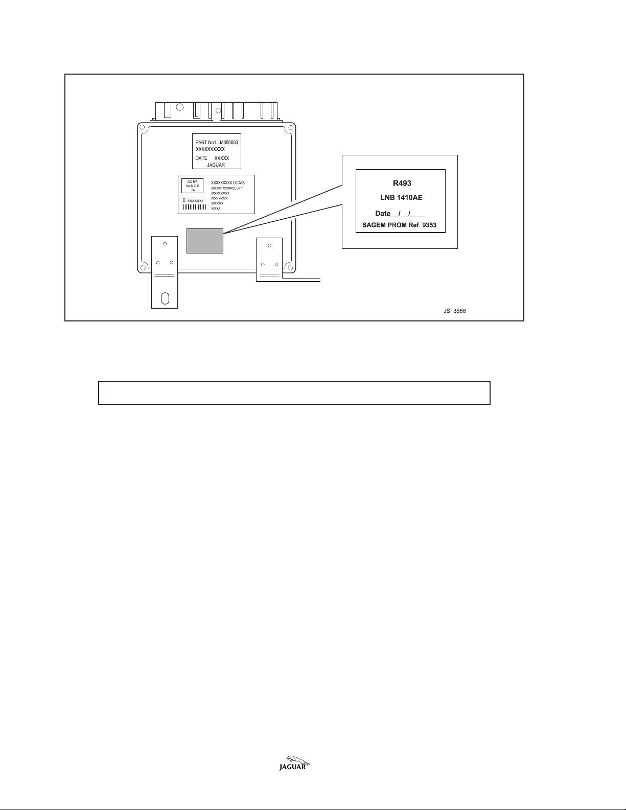
16. Apply the PECUS label from the modification kit to the cover of the ECM. The
new label must not obscure any existing label on the unit (Illustration 7).
Note:Note:
Note: Use this label for T493 also.
Note:Note:
17. Reinstall the ECM in the vehicle, by a reversal of the process used for its
removal.
18. Continue with the procedure for replacing the EGR valve.
Page 10 of 16 Date of issue 11/01 Bulletin Number 17-12 Amended 08/02
EE
GR GR
VV
ALAL
E
EE
GR
GR GR
VE HARNESSVE HARNESS
V
AL
VE HARNESS
VV
ALAL
VE HARNESSVE HARNESS
ILLUSTRATION 8
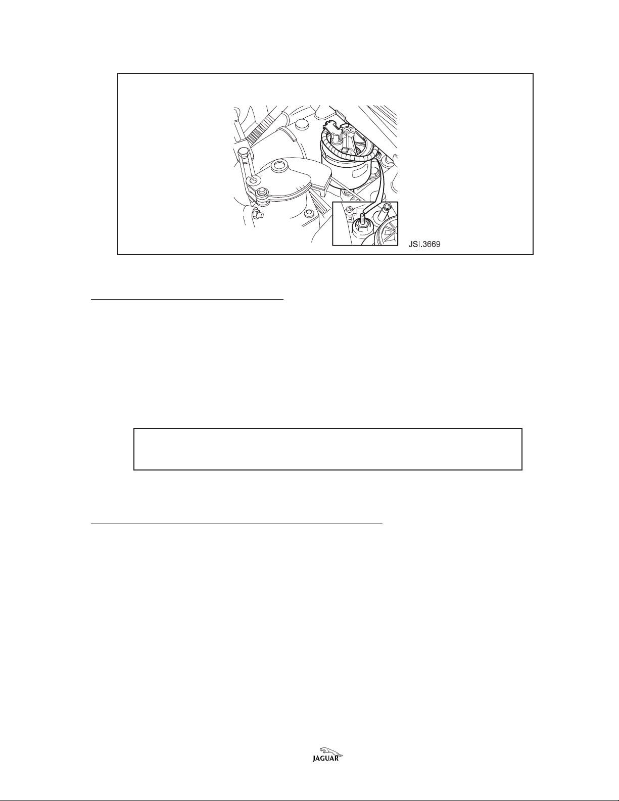
ISSUE 2 - REPLACING EGR VALVE
1. Open the hood and place covers over the fenders.
2. Disconnect the EGR valve harness connector (Illustration 8).
3. Remove the EGR valve securing bolts.
4. Remove the EGR valve and valve gasket.
5. Clean the valve mating faces.
6. To reinstall the new EGR valve and gasket, reverse the EGR valve removal
process.
Note:Note:
Note: Care must be taken not to damage the EGR valve securing
Note:Note:
bolts. Torque figure: 23–27 Nm (17–20 lb ft).
7. Continue with the procedure for replacing the throttle spring.
ISSUE 3 - REPLACING THROTTLE RETURN SPRING
1. Disconnect the inner accelerator cable from the throttle assembly.
2. Remove the cruise control linkage pin and circlip.
3. After removing the three Torx head screws that retain the throttle assembly
cap to the pedestal, carefully remove the cap sub-assembly. Note the position
of the straight extension of the throttle return spring.
Bulletin Number 17-12 Amended 08/02 Date of issue 11/0 1 Page 11 of 16
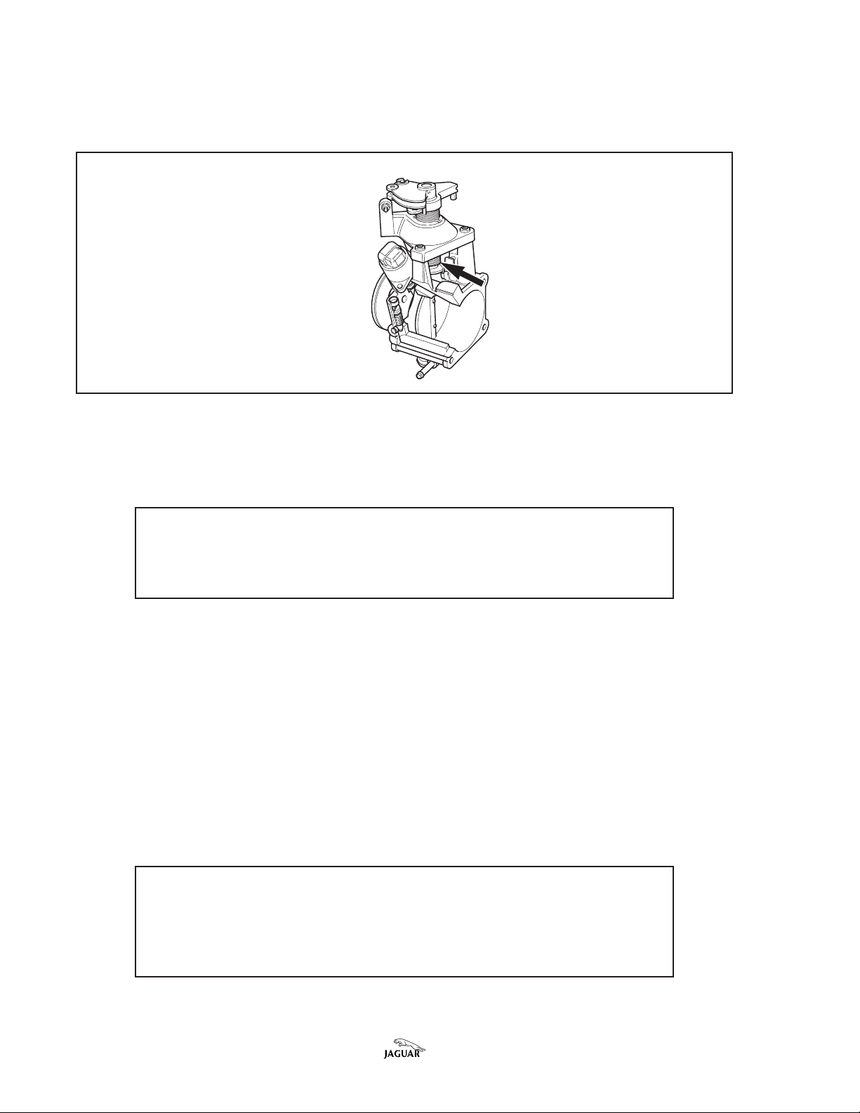
4. Unhook the throttle torsion spring (Illustration 9) from the throttle shaft
actuator and then remove the spring and the sleeve from the shaft.
THROTHRO
TTLE SPRINGTTLE SPRING
THRO
TTLE SPRING
THROTHRO
TTLE SPRINGTTLE SPRING
ILLUSTRATION 9
5. Remove the sleeve from the spring and discard the spring.
6. Insert the sleeve into the replacement spring. Install the sleeve and spring on
the throttle shaf t and hook the spring on to the actuator.
Note:Note:
Note: The throttle return spring must be tensioned, (pre-loaded)
Note:Note:
by rotating the straight extension one full turn countercloc kwise
until it can be installed in the same position as the original
spring.
7. Carefully reinstall the cap to the throttle assembly noting the lever location,
and install and tighten the screws.
8. Reconnect the cruise control linkage.
9. Reconnect the accelerator cable to the throttle assembly.
10. Check the operation of the throttle assembly.
11. Remove fender covers, reconnect the battery, reinstall the battery cover, and
close the lid of the luggage compartment. Reset the vehicle clock and
customer preferences.
12. Using the WDS, perform the oxygen sensors orientation test. (Select set-up
and configuration, engine and transmission, oxygen sensor orientation.)
13. Using the WDS, perform the throttle potentiometer adaptation test.
Note:Note:
Note: During the throttle pot adaptation test por tion of the engine
Note:Note:
set-up procedure, the WDS will ask if a new throttle position
sensor has been installed. Answer this question with YES even
though the existing sensor is being reused. This action will allow
the WDS to reset a larger set of parameters.
14. Check for the presence of any erroneous diagnostic trouble codes (DTCs). If
DTCs are present, they should be recorded, and then cleared.
Page 12 of 1 6 Date of issue 11/01 Bulletin Number 17-12 Amended 08/02
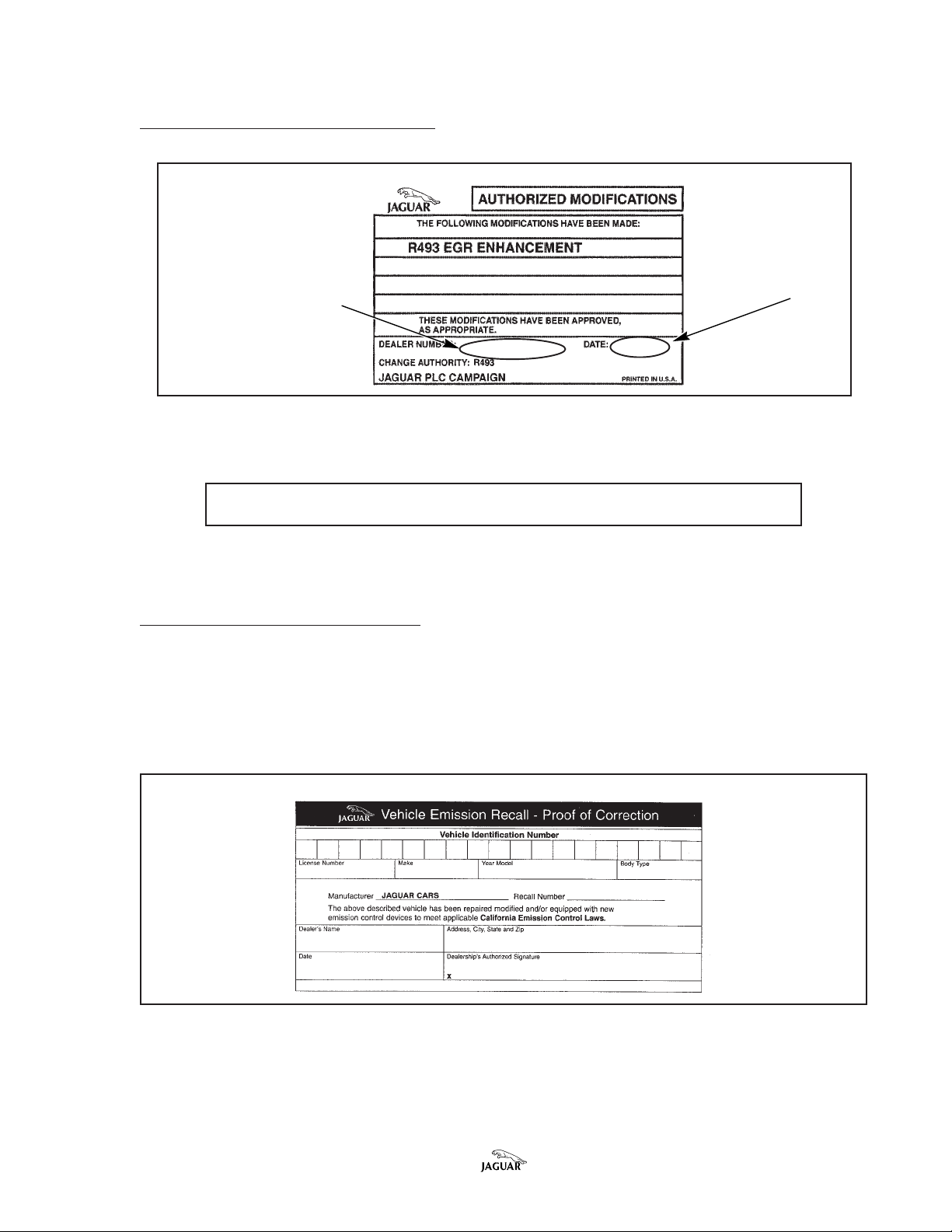
APPLYING MODIFICATION LABEL
MODIFICAMODIFICA
MODIFICA
MODIFICAMODIFICA
WRITE IN DEALER NUMBERWRITE IN DEALER NUMBER
WRITE IN DEALER NUMBER
WRITE IN DEALER NUMBERWRITE IN DEALER NUMBER
TION LABEL (ALL TION LABEL (ALL
TION LABEL (ALL
TION LABEL (ALL TION LABEL (ALL
VEHICLES INCLUDING CA. VEHICLES INCLUDING CA.
VEHICLES INCLUDING CA.
VEHICLES INCLUDING CA. VEHICLES INCLUDING CA.
AND MA.)AND MA.)
AND MA.)
AND MA.)AND MA.)
WRITE IN DWRITE IN D
WRITE IN D
WRITE IN DWRITE IN D
AA
TETE
A
TE
AA
TETE
ILLUSTRA TION 10
Note:Note:
Note: Use this label for T493 also.
Note:Note:
Enter the dealer number and date on the authorized modification label and apply
the label (Illustration 10, part no. R 493 STK) next to the left hood hinge.
PROOF OF CORRECTION FORM
California and Massachusetts Dealers (and any other states where required): Fill
out and place the salmon colored “Vehicle Emission Recall - Proof of Correction”
form (Illustration 11, par t no. S CAL RCL) in the vehicle glove compartment.
PROOF OF CORRECTION FORM (CALIFORNIA AND MASSACHUSETTS)
ILLUSTRATION 1 1
Bulletin Number 17-12 Amended 08/02 Date of issue 11/01 Page 13 of 16

ADDITIONAL INITIATIVES
The following are diagnostic procedures that may be followed should a drivability
concern still be apparent after the recall action has been completed. The
completion of any subsequent repairs are subject to normal New Car Warranty or
Select Edition Warranty, or customer pay authorization as appropriate.
BSTfoetaD
eussi
45-21dednemA
89/21
11-7189/21elttorhT
55-8110/20niatsybwolB
eltiTsmotpmySledoMnoitcA
sgulpkrapSgulprettohotegnahC69-5991
SJX
dlocnehwtuhsskcitselttorhT69/5991
gnikcits
nodesolc
enignedloc
nialecropnonoitarolocsiD69-5991
krapsno
sgulp
SJX
SJX
ecivreS
gulptnemecalper
esacknarcyfidoM
metsysrehtaerb
elttorhtnaelcdna
egnahctonoD
anorocrofsgulp
.niatsegrahcsid
Page 14 of 16 Date of issue 11/01 Bulletin Number 17-12 Amended 08/02

PP
ARAR
TS INFORMATS INFORMA
P
AR
TS INFORMA
PP
ARAR
TS INFORMATS INFORMA
TION:TION:
TION:
TION:TION:
The appropriate modification kit for the 1995 MY only (LNC 1411BB) initially will be
allocated to each dealer based on size and volume to ensure an even distribution
and full coverage. After the initial allocation, parts should be ordered from Jaguar
Parts Operations following normal procedures. All other parts required should be
ordered through Jaguar Parts Operations following the normal process.
ELCIHEVEGNARNIVNOITACIFIDOM
SJXYM59136222-577491BB1141CNLBB1141CNL
SJXYM69546622-236222AF1141CNL1JD0141EHL0639
TRAPTIK
BB1141CNLBB1141CNL1 LA0141EHLLA0141EHL
BB1141CNL
YTQMCESETADPUTIK
TRAPSIHTOT
REBMUN
LA0141EHLLA0141EHL2639
LA0141EHL
MORP
.ONDI
All of the PROM kits include 2 PROMs and a revised ‘PECUS’ label to be applied to
the ECM after completing the modification.
DESCRIPTIONDESCRIPTION
DESCRIPTION
DESCRIPTIONDESCRIPTION
EGR valve - XJS VIN 1 94775 – 195695 EGR valve LHE 1 550BA 1
EGR valve - XJS VIN 1 95696 – 226645 LHE 1550AC 1
EGR valve g asket C2A 1231 1
EGR valve bolt FS 1 08251J As required
Throttle return spring NBB 3131AB 1
PP
ARAR
T NUMBERT NUMBER
P
AR
T NUMBER
PP
ARAR
T NUMBERT NUMBER
QTYQTY
QTY
QTYQTY
To obtain R493 Authorized Modification Labels from the Product Legislation and
Compliance Department, refer to Administration Bulletin 6-94 (USA) or 6-16/02
(Canada) titled “Availability of Service Action and Recall Authorized Modification
Labels/stickers.”
DESCRIPTIONDESCRIPTION
DESCRIPTION
DESCRIPTIONDESCRIPTION
R493 Modification Label R 493 STK 1
CA & MA only:
Proof of Correction Form S CAL RCL 1
Bulletin Number 17-12 Amended 08/02 Date of issue 11/01 Page 15 of 16
PP
ARAR
T NUMBERT NUMBER
P
AR
T NUMBER
PP
ARAR
T NUMBERT NUMBER
QTYQTY
QTY
QTYQTY

WW
ARRANARRAN
W
ARRAN
WW
ARRANARRAN
TY INFORMATY INFORMA
TY INFORMA
TY INFORMATY INFORMA
TION:TION:
TION:
TION:TION:
Warranty claims should be submit ted quoting the information found in the table
below. This will result in payment of the stated time and, where applicable parts/
miscellaneous expense codes as listed.
Drive in/drive out may only be claimed when the vehicle has been brought in for
this action alone to be undertaken.
Please use option code of X and
also enteralso enter
also enter the SRO (s) and parts details on the
also enteralso enter
claim applicable to the repair completed.
RR
ecall ecall
ecall
ecall ecall
T493 - 1T493 - 1
T493 - 1
T493 - 1T493 - 1
R
RR
REPLACEMENT OF PROMS IN ECM
VV
ehicleehicle
V
ehicle
VV
ehicleehicle
XJS 4.0 VIN Range:
194775 - 222631 Replace PROMS within ECM 18.91.18 0.7 LNC 1411BB PROM Kit 1
EGR VALVE & GASKET REPLACEMENT
XJS 4.0 VIN Range:
194775 - 195695 Replace EGR valve & gasket 17.45.01 0.2 LHE 1550BA EGR valve 1
995 MY XJS 4.0L995 MY XJS 4.0L
995 MY XJS 4.0L
995 MY XJS 4.0L995 MY XJS 4.0L
RR
epairepair
R
epair
RR
epairepair
SROSRO
SRO
SROSRO
TT
T
TT
imeime
ime
imeime
PP
arar
t Numbert Number
P
ar
t Number
PP
arar
t Numbert Number
C2A 1231 Gasket 1
FS 108251J Set screw As Req.
DescriptionDescription
Description
DescriptionDescription
QTYQTY
QTY
QTYQTY
THROTTLE RETURN SPRING REPLACEMENT
XJS 4.0 VIN Range
194775 - 226645 Replace throttle return spring 19.91.46 0.2 NBB 3131AB Throttle return
spring 1
DRIVE IN/DRIVE OUT
ALL Drive in/drive out 10.10.10 0 .1
RR
ecall R493 - 1ecall R493 - 1
R
ecall R493 - 1
RR
ecall R493 - 1ecall R493 - 1
REPLACEMENT OF PROMS IN ECM
VV
ehicleehicle
V
ehicle
VV
ehicleehicle
XJS 4.0 VIN Range:
222632 - 226645 Replace PROMS within ECM 18.91.18 0.7 LNC 1411FA PROM Kit 1
EGR VALVE & GASKET REPLACEMENT
XJS 4.0 VIN Range:
195696 - 226645 Replace EGR valve & gasket 17.45.01 0.2 LHE 1550AC EGR valve 1
THROTTLE RETURN SPRING REPLA CEMENT
XJS 4.0 VIN Range
194775 - 226645 Replace throttle return spring 19.91.46 0.2 NBB 3131AB Throttle return
996 MY XJS 4.0L996 MY XJS 4.0L
996 MY XJS 4.0L
996 MY XJS 4.0L996 MY XJS 4.0L
RR
epairepair
R
epair
RR
epairepair
SROSRO
SRO
SROSRO
TT
T
TT
imeime
ime
imeime
PP
arar
t Numbert Number
P
ar
t Number
PP
arar
t Numbert Number
C2A 1231 Gasket 1
FS 108251J Set Screw As Req.
DescriptionDescription
Description
DescriptionDescription
spring 1
QTYQTY
QTY
QTYQTY
DRIVE IN/DRIVE OUT
ALL Drive in/drive out 10.10.10 0 .1
Page 16 of 1 6 Date of issue 11/01 Bulletin Number 17-12 Amended 08/02

DATE
10/95Sedan Range
18-04
SERVICE
Security System – Rear Door False Alarm –
Repair Information
TECHNICAL BULLETIN
MODEL
1995 MY
Sedan Range
VIN
720001-735432
ISSUE:ISSUE:
ISSUE:
ISSUE:ISSUE:
Sedan Range vehicles within the above VIN range may experience a security
system false alarm that is recorded in the last alarm data as a door instrusion. On
some vehicles, the side of the actuator connector facing the rear door lock
actuator was incorrectly molded. This may increase the possibility of water
entering the connector, which may trigger the vehicle security system
intermittently.
ACTION:ACTION:
ACTION:
ACTION:ACTION:
In case of a customer complaint of a security system false alarm on a Sedan
Range vehicle within the above VIN range, proceed as follows:
1. Inspect the rear door lock actuator on the affected doors for signs of water
entry.
2. If corrosion is found, clean the connector and seal the connector with Jaguar
electrical contact grease, part no. JLM 11472.
3. If the corrosion is too extensive, the door harness and/or door lock actuator
should be replaced as necessary. The replacement parts are the latest design.
PP
ARAR
TS INFORMATS INFORMA
P
AR
TS INFORMA
PP
ARAR
TS INFORMATS INFORMA
DESCRIPTIONDESCRIPTION
DESCRIPTION
DESCRIPTIONDESCRIPTION
Jaguar electrical grease JLM 11472 *
Right rear door latch/actuator assembly GNA 2550BD 1
Left rear door latch/actuator assembly GNA 2551BD 1
Right rear door harness LNA 3190CF 1
Left rear door harness LNA 3190FE 1
*= Claim no more than 25% of container cost per vehicle.
TION:TION:
TION:
TION:TION:
PP
ARAR
T NUMBERT NUMBER
P
AR
T NUMBER
PP
ARAR
T NUMBERT NUMBER
QTYQTY
QTY
QTYQTY
Date of issue 10/95 Bulletin Number 18-04 Page 1 of 2

WW
ARRANARRAN
W
ARRAN
WW
ARRANARRAN
FF
AA
ULUL
F
A
UL
FF
AA
ULUL
CODECODE
CODE
CODECODE
TY INFORMATY INFORMA
TY INFORMA
TY INFORMATY INFORMA
TT
T
TT
R.O.R.O.
R.O.
R.O.R.O.
NUMBERNUMBER
NUMBER
NUMBERNUMBER
TION:TION:
TION:
TION:TION:
DESCRIPTIONDESCRIPTION
DESCRIPTION
DESCRIPTIONDESCRIPTION
TIMETIME
TIME
TIMETIME
ALLALL
ALL
ALLALL
RB BD MB 86.25.47 Left rear door lock actuator - replace 1.00 hrs.
(with diagnostic time)
RB BD MB 86.25.47.09 Left rear door lock actuator - replace 0.65 hrs.
(without diagnostic time)
RB BF MB 86.25.47 Right rear door lock actuator - replace 1.00 hrs.
(with diagnostic time)
RB BF MB 86.25.47.09 Right rear door lock actuator - replace 0.65 hrs.
(without diagnostic time)
LJ GK PS 86.70.47 Replace left rear door harness 1.15 hrs.
(with diagnostic time)
LJ GK PS 86.70.47.09 Replace left rear door harness 0.80 hrs.
(without diagnostic time)
LJ HK PS 86.70.47 Replace right rear door harness 1.15 hrs.
(with diagnostic time)
LJ HK PS 86.70.47.09 Replace right rear door harness 0.80 hrs.
(without diagnostic time)
O
OO
OO
WW
ANCEANCE
W
ANCE
WW
ANCEANCE
Page 2 of 2 Bulletin Number 18-04 Date of issue 10/95

DATE
10/95Sedan Range
18-05
SERVICE
Security System – Panic Alarm –
Diagnostic Procedure –
Service Action S635
ISSUE:ISSUE:
ISSUE:
ISSUE:ISSUE:
The Panic Alarm may not operate on some 1995 MY Sedan Range vehicle in the
above VIN range. The absence of the Panic Alarm may result from either a
transmitter problem or an Security Locking Control Module, (SLCM) problem or a
combination of both.
ACTION:ACTION:
ACTION:
ACTION:ACTION:
All vehicles in the above VIN range should be inspected, regardless whether in
dealer stock or in service. Check customer vehicles at the next service opportunity
or in response to a customer complaint as described below.
SECURITY SYSTEM PANIC ALARM OPERATION
NOTE:NOTE:
NOTE: Remote transmitters without any identification mark (113
NOTE:NOTE:
type) must be replaced with the later 101 type. The 101 type can
be identified by a pink paint spot on the blue tags supplied with
transmitters and all new vehicles. If the blue identification tag is
not available, check the oscillator identification mark (101 or 113)
on the printed circuit board in the transmitter.
TECHNICAL BULLETIN
MODEL
1995 MY
Sedan Range
VIN
720001 - 739235
1. Remove the ignition key from the ignition switch and ensure that the vehicle
doors are closed.
2. Check the operation of the Panic Alarm by pressing either button on the
transmitter for at least 3 seconds and then releasing it.
NOTE:NOTE:
NOTE: Perform the Panic Alarm test outside of shop area, if
NOTE:NOTE:
possible, due to the noise level.
3. Repeat the operation using the other transmitter button.
4. The Panic Alarm will sound for five times the normal full alarm period.
5. Insert the ignition key and turn to position I or II and back to 0 to cancel the
Panic Alarm.
NOTE:NOTE:
NOTE: When checking the Panic Alarm on vehicles equipped
NOTE:NOTE:
with the battery transit relay, the checking procedure described
above must be carried out within 30 seconds of the initial
removal of the ignition key.
6. Remove the key and begin checking the second transmitter.
Date of issue 10/95 Bulletin Number 18-05 Page 1 of 5

7. If the second transmitter needs to be checked after the 30 second period has
elapsed, the ignition should first be switched on and off as described in step
5.
CHECKING THE REPLACEMENT TRANSMITTER
1. A maximum of five transmitters can be programmed for one system.
2. Remove the ignition key from the ignition switch and ensure that the vehicle
doors and trunk are closed.
3. Check the operation of the Panic Alarm by pressing first one and then the
other button as described above.
4. If the Panic Alarm functions, no further action is necessary.
5. If the Panic Alarm does not function, and the system is equipped with the 101
type remote transmitter, (pink spot), DO NOT attempt to restore the Panic
Alarm, install a new SLCM. (Refer to “Replacing the SLCM”).
6. When the SLCM has been replaced, check the operation of the Panic Alarm as
described above.
REPLACING THE SLCM
SECURITY LOCKING CONTROL MODULESECURITY LOCKING CONTROL MODULE
SECURITY LOCKING CONTROL MODULE
SECURITY LOCKING CONTROL MODULESECURITY LOCKING CONTROL MODULE
MOUNTING STUDSMOUNTING STUDS
MOUNTING STUDS
MOUNTING STUDSMOUNTING STUDS
JSI-2525
1. Disconnect the vehicle battery.
2. Remove the luggage compartment carpet, front liner, seal retainer and the
side liner.
3. Loosen and remove the nuts retaining the SLCM, Illustration 1.
4. Withdraw the SLCM mounting studs from the mounting holes, (arrows,
Illustration 1) in the body support bracket.
5. Disconnect the SLCM from the vehicle harness, noting the position of the
connectors.
Page 2 of 5 Bulletin Number 18-05 Date of issue 10/95

6. Connect the harness connectors to the new SLCM in the same order as they
were on the original module.
7. Insert the SLCM mounting studs through the holes in the support bracket and
install nuts.
8. Reconnect battery and install trunk trim.
PROGRAMMING THE HAND TRANSMITTER.
Use the PDU to reprogram the security system RF handset transmitters. The
following method can be used to manually reprogram handset transmitters:
NOTE:NOTE:
NOTE: All RF handset transmitters belonging to the vehicle
NOTE:NOTE:
being serviced must be available. If the learning process is
carried out without having all the transmitters present, all
previous transmitter codes will be overwritten, rendering the
missing transmitters inoperable.
1. Open the trunk lid and driver’s door.
2. Turn the ignition switch to the ON or II position.
3. Rock the valet switch located in the center console storage compartment
(Illustration 2) 5 times. A single confirmation chirp and flash of the
headlamps indicate that the security system has entered the learning mode.
NOTE:NOTE:
NOTE: If difficulty is experienced entering the learning mode,
NOTE:NOTE:
check that the valet switch is functioning properly.
VV
ALET SWITCHALET SWITCH
V
ALET SWITCH
VV
ALET SWITCHALET SWITCH
JWX-163
ILLUSTRATION 2
Date of issue 10/95 Bulletin Number 18-05 Page 3 of 5

4. Press the arm/lock (larger) button of the first transmitter. This transmitter will
be linked to position 1 of the seat/column/mirror memory. A tone will confirm
that the transmitter code was accepted. If no transmitter buttons are pushed,
the SLCM will also time out after 15 seconds of inactivity, indicated by two
chirps.
5. Rock the valet switch once. Two short chirps will signal that the system is
prepared to accept the second transmitter.
6. Press the arm/lock button of the second transmitter. This transmitter will be
linked to the position 2 of the seat/column/mirror memory. A tone will
confirm that the transmitter code was accepted.
7. Rock the valet switch once. Three short chirps will signal that the system is
prepared to accept the third transmitter.
8. Press the arm/lock button of the third transmitter. A tone will confirm that the
transmitter code was accepted. This transmitter and any others will not be
linked to a position in the seat/column/mirror memory.
9. The process of pressing the valet switch and waiting for the number of chirps
equivalent to the transmitter number can be repeated for a fourth and fifth
transmitter. The valet switch can be pressed to cycle through the unneeded
transmitter programming sequences. The SLCM will also time out after 15
seconds of inactivity, indicated by two chirps. This will save the transmitter
codes entered up to this point.
10. Turn the ignition switch off, remove the key, and close the doors and trunk lid.
11. Check for proper system operation including the recall of seat, steering wheel
and mirror memory positions 1 and 2 from the handset transmitter.
WW
ARRANARRAN
W
ARRAN
WW
ARRANARRAN
TY INFORMATY INFORMA
TY INFORMA
TY INFORMATY INFORMA
TION:TION:
TION:
TION:TION:
Service Action S635
VEHICLEVEHICLE
VEHICLE
VEHICLEVEHICLE
Sedan Range 1995 MY HA Check, replace and reprogram 0.15 hrs.
VIN 727000 - 739235 new transmitters when
Model codes 2310, 2311, performed at PDI or in
2313, 2314, 2512 conjunction with another repair
Sedan Range 1995 MY HB Check, replace and reprogram 0.30 hrs.
VIN 727000 - 739235 new transmitters
Model codes 2310, 2311, - only repair performed
2313, 2314, 2512 - with drive in/out time
SUMMARSUMMAR
SUMMAR
SUMMARSUMMAR
CODECODE
CODE
CODECODE
YY
DESCRIPTIONDESCRIPTION
Y
DESCRIPTION
YY
DESCRIPTIONDESCRIPTION
(no drive in/out time)
TIMETIME
TIME
TIMETIME
ALLALL
ALL
ALLALL
OO
O
OO
WW
ANCEANCE
W
ANCE
WW
ANCEANCE
Page 4 of 5 Bulletin Number 18-05 Date of issue 10/95

Sedan Range 1995 MY HC Check, replace and reprogram 0.60 hrs.
VIN 727000 - 739235 new transmitters and replace
Model codes 2310, 2311, SLCM when performed at PDI or
2313, 2314, 2512 in conjunction with another repair
(no drive in/out time)
Sedan Range 1995 MY HD Check, replace and reprogram 0.75 hrs.
VIN 727000 - 739235 new transmitters and replace
Model codes 2310, 2311, SLCM - only repair performed
2313, 2314, 2512 - with drive in/out time
CLAIM SUBMISSION PROCEDURE:
Warranty summary codes have been assigned to this service action in order to
simplify claim submission. The dealership will be reimbursed the parts and labor
time allowance as indicated.
DCS DEALERS
Submit claims using the appropriate summary code for the vehicle model and
work performed. Follow standard campaign submission procedures.
NON-DCS DEALERS
Submit claims on the Recall Campaign Summary form W-25. Enter the appropriate summary code for the vehicle model and work performed in the Repair Code
column. Do not use the W-1 warranty claim form.
Date of issue 10/95 Bulletin Number 18-05 Page 5 of 5

DATE
10/95Sedan Range
18-06
SERVICE
Security System – Handset Transmitter –
Manual Programming
ISSUE:ISSUE:
ISSUE:
ISSUE:ISSUE:
The Security System RF handset transmitters can be programmed manually in
case a PDU is not immediately available.
ACTION:ACTION:
ACTION:
ACTION:ACTION:
Use the following method to manually reprogram security system RF handset
transmitters:
TECHNICAL BULLETIN
MODEL
Sedan Range
VIN
1995-96 MY
720001-ON
NOTE:NOTE:
NOTE: All RF handset transmitters belonging to the vehicle
NOTE:NOTE:
being serviced must be available. If the learning process is
carried out without having all the transmitters present, all
previous transmitter codes will be overwritten, rendering the
missing transmitters inoperable.
1. Open the trunk lid and driver’s door.
2. Turn the ignition switch to the ON or II position.
Date of issue 10/95 Bulletin Number 18-06 Page 1 of 3

VV
ALET SWITCHALET SWITCH
V
ALET SWITCH
VV
ALET SWITCHALET SWITCH
JWX-163
ILLUSTRATION 1
3. Rock the valet switch located in the center console storage compartment
(Illustration 1) 5 times. A single confirmation chirp and flash of the
headlamps indicate that the Security Locking Control Module (SLCM) has
entered the learning mode.
NOTE:NOTE:
NOTE: If difficulty is experienced entering the learning mode,
NOTE:NOTE:
check that the valet switch is functioning properly by removing it
and checking continuity.
4. Press the arm/lock (larger) button of the first transmitter. This transmitter will
be linked to position 1 of the seat/column/mirror memory. A tone will confirm
that the transmitter code was accepted. If no transmitter buttons are pushed,
the SLCM will also time out after 15 seconds of inactivity, indicated by two
chirps.
5. Rock the valet switch once. Two short chirps will signal that the system is
prepared to accept the second transmitter.
6. Press the arm/lock button of the second transmitter. This transmitter will be
linked to the position 2 of the seat/column/mirror memory. A tone will
confirm that the transmitter code was accepted.
7. Rock the valet switch once. Three short chirps will signal that the system is
prepared to accept the third transmitter.
Page 2 of 3 Bulletin Number 18-06 Date of issue 10/95

8. Press the arm/lock button of the third transmitter. A tone will confirm that the
transmitter code was accepted. This transmitter and any others will not be
linked to a position in the seat/column/mirror memory.
9. The process of pressing the valet switch and waiting for the number of chirps
equivalent to the transmitter number can be repeated for a fourth and fifth
transmitter. The valet switch can be pressed to cycle through the unneeded
transmitter programming sequences. The SLCM will also time out after 15
seconds of inactivity, indicated by two chirps. This will save the transmitter
codes entered up to this point.
10. Turn the ignition switch off, remove the key, and close the doors and trunk lid.
11. Check for proper system operation including the recall of seat, steering wheel
and mirror memory positions 1 and 2 from the handset transmitter.
Date of issue 10/95 Bulletin Number 18-06 Page 3 of 3

Sedan Range
DATE
11/94
18-09
SERVICE
Security System Transmitter –
Battery Replacement
ISSUE:
Attempting to pry the battery access cover off of the security system transmitter may cause the
transmitter to separate and damage electronic components.
ACTION:
To prevent damage when removing the battery access cover of 1995 MY Sedan Range security
system transmitters, use the following procedure.
SECURITY SYSTEM TRANSMITTER BATTERY ACCESS COVER REMOVAL
1. Insert a small (1/16" thick) screwdriver between the access cover and body
(Illustration 1).
SECURITY SYSTEM TRANSMITTER
TECHNICAL BULLETIN
MODEL
Sedan Range
VIN
1995 MY
720001-ON
86-135.1
ILLUSTRATION 1
2. Push the screwdriver straight in to release the lock as shown in Illustration 2.
CAUTION: Twisting the screwdriver or attempting to pry the cover open will damage the transmitter.
Bulletin Number 18-09 Page 1 of 2

3. The internal spring will push the access cover open.
RELEASING THE BATTERY ACCESS COVER
INSERT SCREWDRIVER PUSH IN TO RELEASE LOCK TAB
ILLUSTRATION 2
NOTE: Dispose of used batteries according to local laws.
86-135.2
Page 2 of 2 Bulletin Number 18-09

DATE
10/95Sedan Range
18-10
SERVICE
TECHNICAL BULLETIN
MODEL
Sedan Range
1995-96 MY
Security System – Fault Diagnosis Guide
VIN
720001-ON
ISSUE:ISSUE:
ISSUE:
ISSUE:ISSUE:
Additional fault tracing information for Sedan Range vehicle security system.
ACTION:ACTION:
ACTION:
ACTION:ACTION:
Refer to the possible symptom and cause information grouped by topic on the
following pages.
FAUL T TRACING CONTENTS PAGE
False Alarms...............................................................2
Security System not arming .....................................3
Transmitter totally inoperative..................................4
Poor transmitter range ..............................................5
SLCM does not enter Manual Learn mode ..............5
Checking the “Last Alarm” data using the PDU.....6
Date of issue 10/95 Bulletin Number 18-10 Page 1 of 7

Page 2 of 7 Bulletin Number 18-10 Date of issue 10/95
FALSE ALARMS
The cause of the last 8 vehicle
alarms may be checked by using
the PDU to interrogate the Security
Locking Control Module (SLCM).
The causes of the alarms are stored
in the Last Alarm Data section of
the Security Diagnostic PDU
software. See flowchart on page 6.
It is possible for False Alarms to be
generated along with the following
symptoms:
1. Symptoms:
• Transmitter will intermittently not
lock the vehicle and/or
the door locks “cycle” and/or
the security system emits error
tones.
• Vehicle will not start and alarm is
inoperative.
• Alarm self-activates.
• When “Drive” is selected, all
doors do not lock automatically.
VIN Range affected: 720001 - 735432
Possible cause:
Moisture contamination in one
or both right and left door
multiplugs RD3. Experience
has shown that the multiplug
on the right rear door is more
prone to this problem and
should be checked first. If the
connector is corroded, both the
door lock module harness and
the door harness should be
replaced.
2. Symptom
• Intermittent error tone
whenever the transmitter
button is pressed and/or the
system will not arm.
VIN Range affected: 720001-ON
Possible cause:
Faulty ignition switch in
steering lock.

Date of issue 10/95 Bulletin Number 18-10 Page 3 of 7
3. Symptom
SECURITY SYSTEM NOT ARMING
1. If arming of the security system
is inhibited when using either
the key or the transmitter,
check that the following inputs
to the SLCM are not active:
• Trunk lock intermittently does not
release from either the
Possible cause:
Faulty “Trunk Lid Ajar” switch.
transmitter or from the internal or
external trunk lock release
switches and/or
error tones occur following
security system arming.
VIN Range affected: 720001-723274
Function Connector Identification
Ignition key “In” SLCM Connector CA 19-18
(UR)
Ignition auxiliary “On” SLCM Connector CA 18-8
(WN)
Ignition “On” SLCM Connector CA 19-17 (WO)
(Wire color codes: U=Blue, R=Red, W=White, N=Brown, O=Orange)

Page 4 of 7 Bulletin Number 18-10 Date of issue 10/95
2. If the security system will not
Function Connector Identification
arm from the remote
transmitter, with all the doors
properly closed, the following
inputs to the SLCM should be
checked:
Passenger door ajar SLCM Connector CA 18-1 (UO)
Driver’s door ajar SLCM Connector CA 18-7 (PR)
Rear door ajar SLCM Connector CA 19-21 (P)
(Wire color codes: U=Blue, R=Red, W=White, N=Brown, O=Orange)
If any of the circuits are suspect, also check for entry of moisture into the
rear door multiplug RD3.
TRANSMITTER TOTALLY INOPERATIVE
If the transmitter is totally inoperative, check whether the
LEDs on the transmitter illuminate when the “Lock” or
“Unlock” button is pressed.
If the LEDs do NOT illuminate, check the transmitter
battery voltage levels. Each battery should be
approximately 3 volts.
If the LEDs DO illuminate, check that the transmitter and
security system have not lost their code synchronization.
The system is designed with a rolling code window of
100 activations of the transmitter. This means that if the
transmitter is operated 100 times out of range of the
vehicle to which it is coded, it will lose synchronization
with the vehicle. If this occurs, repeated operations of
the transmitter will not unlock the vehicle.
In this case, the security system may be disarmed by
unlocking the doors using the vehicle key.
Once the vehicle is in an unlocked and disarmed state,
the RF transmitter(s) will re-synchronize to the vehicle
after 3 activations within signal range.
NOTE:NOTE:
NOTE: If the transmitter and the SLCM
NOTE:NOTE:
have lost code synchronization, and the
transmitter button is pressed while the
vehicle is locked and armed, the SLCM
may enter the “Anti-scan” mode. This
will inhibit any transmitter operation for
approximately 2 minutes.

Date of issue 10/95 Bulletin Number 18-10 Page 5 of 7
POOR TRANSMITTER RANGE
If the transmitter operates, but the
range is poor, first check the range
of the second transmitter. If both
transmitters have equally poor
range, check the following before
replacing any items.
1. Check the voltage of the
transmitters’ batteries. Each
battery should measure
approximately 3 volts.
2. Check the integrity of the
harness for the following
inputs to the SLCM:
Function Connector Identification
RF Ground SLCM Connector CA 20-7 (BRD)
RF Antenna Signal SLCM Connector CA 20-15 (WN)
(WIre color code: W=White, N=Brown, BRD=Shielded cable)
SLCM DOES NOT ENTER THE
MANUAL LEARN MODE
If the SLCM will not enter the
“Learn mode”, check the
following:
• The ignition key must be in the
“Ignition On” position.
• The security system must be
disarmed.
• All the vehicle doors must be
unlocked.
• The vehicle must not be in the
“Valet” mode. (Open the trunk
lid before attempting to enter
the “Learn” mode.)
If the points at the left have been checked and the SLCM still will not enter
the “Learn” mode, check the integrity of the following inputs to the
SLCM.
Function Connector Identification
Lock Actuator Status (RH) SLCM Connector CA 18-12 (YB)
Lock Actuator Status (LH) SLCM Connector CA 18-10 (YR)
Ignition Auxiliary ON SLCM Connector CA 18-8 (WN)
Trunk Valet mode switch SLCM Connector CA 19-6 (YW)
Ignition ON SLCM Connector CA 19-17 (WO)
(Wire color code: Y=Yellow, B=Black, R=Red, W=White, N=Brown,

CHECKING THE “LAST ALARM” DATA USING THE PORTABLE DIAGNOSTIC UNIT
Main Menu
**
DiagnosticsDiagnostics
*
Diagnostics
DiagnosticsDiagnostics
**
**
* Digitial Multimeter
**
**
* Training
**
**
* User Self Te st
**
Main Menu
**
DiagnosticsDiagnostics
*
Diagnostics
DiagnosticsDiagnostics
**
**
* Set up
**
**
* TOOLBOX
**
**
* OBDII Report
**
**
* Vehicle Data Viewer
**
**
* Exit
**
Vehicle Identification
773214
789
CL456
123
0
OPERATOR MESSAGE
Ensure the customer fault has
been verified before carrying
out diagnostics
BODY SYSTEMS
**
* AUDIBLE WARNINGS
**
**
* CIGAR LIGHTERS
**
**
* IN CAR ENTERTAINMENT
**
**
* RADIO TELEPHONE
**
**
* SEATS
**
**
SECURITY SYSTEMSECURITY SYSTEM
*
SECURITY SYSTEM
SECURITY SYSTEMSECURITY SYSTEM
**
**
* SUN ROOF
**
**
* WASH/WIPE CIRCUITS
**
**
* GEARSHIFT & KEY LOCK
**
**
* POLYCHROMIC REAR
**
VIEW MIRROR
**
* HEATED WASH JETS
**
**
* SCREEN HEATERS
**
**
* STEERING COLUMN &
**
MIRROR MOVEMENT
**
* GARAGE DOOR OPENER
**
**
* AIR BAG
**
**
* POWER ASSISTED
**
STEERING
Vehicle Features
Steering LHD RHD
Engine AJ16 V12
Transmission MANUAL AUTO
Air
Conditioning YES NO
Security
System YES NO
Driver’s
Memory Seat YES NO
Passenger’s
Memory Seat YES NO
Extended
Wheelbase YES NO
FAULT DIAGNOSTICS
**
* ENGINE & TRANSMISSION
**
**
* INSTRUMENTATION
**
**
* LIGHTING
**
**
* CLIMATE CONTROL SYSTEMS
**
**
BODY SYSTEMSBODY SYSTEMS
*
BODY SYSTEMS
BODY SYSTEMSBODY SYSTEMS
**
**
* DOOR SYSTEMS
**
**
* BRAKE SYSTEM
**
**
* POWER FEEDS
**
**
* SERIAL COMM BUS TEST
**
**
* EXIT
**
SECURITY SYSTEM
**
LALA
SS
T T
LA
LALA
ALARM DALARM D
S
T
ALARM D
SS
T T
ALARM DALARM D
*
**
**
* IGNITION
**
**
* KEY IMMOBILISATION
**
**
* VISIBLE OUTPUTS
**
**
* SENSORS
**
**
* PROTECTED ENTRIES
**
**
* SOUNDERS AND HORN
**
**
* REMOTE RECALL
**
**
* REMOTE TRANSMITTER
**
**
* REMOTE ALL CLOSE
**
**
* BOOR FUSE 4
**
**
* PANIC SWITCH
**
**
* COMPLETE TEST
**
AA
TT
AA
A
T
A
AA
TT
AA
Page 6 of 7 Bulletin Number 18-10 Date of issue 10/95

PP
ARAR
TS INFORMATS INFORMA
P
AR
TS INFORMA
PP
ARAR
TS INFORMATS INFORMA
TION:TION:
TION:
TION:TION:
Any parts determined necessary as a result of tracing a fault in the Security
system should be ordered as necessary from Jaguar Parts.
WW
ARRANARRAN
W
ARRAN
WW
ARRANARRAN
TY INFORMATY INFORMA
TY INFORMA
TY INFORMATY INFORMA
TION:TION:
TION:
TION:TION:
Wa rranty claims must be submitted in accordance with the current published
Jaguar Warranty Policy and Procedures Manual, and Amendments.
Date of issue 10/95 Bulletin Number 18-10 Page 7 of 7

DATE
6/97Sedan Range
18-12
SERVICE
Security System – Frequency Change –
Rear Glass Antenna
TECHNICAL BULLETIN
MODEL
Sedan Range LWB
VIN
1996 MY
754307-758728
ISSUE:ISSUE:
ISSUE:
ISSUE:ISSUE:
Some long wheelbase (LWB) Sedan Range vehicles within the above VIN range
were equipped with 315 MHz Security and Locking Control Modules (SLCM) and
key fob transmitters in spite of having rear glass antennas intended for 433 MHz
systems. However, this condition has not been found to have a significant effect
on the performance of the security system.
While the SLCM and rear glass antenna do not need to match, the key fob
transmitters and the SLCM must be the same frequency. A key fob transmitter of
one frequency will not function with an SLCM of the other frequency.
Long wheelbase vehicles beginning with VIN 758729 are equipped with a
complete 433 MHz system. Short wheelbase vehicles were changed to the 433
MHz system starting with VIN 759614. The 433 MHz was introduced to give
improved reliability and more consistent performance.
The frequency is incorporated in the last 3 digits of the FCC ID number. This
number is located on the back of the key fob transmitter battery cover and on the
sticker on the SLCM. The antenna is located near the top center of the rear glass
and can be identified by its configuration (Illustration 1).
REAR GLAREAR GLA
REAR GLA
REAR GLAREAR GLA
SS SECURITY SSS SECURITY S
SS SECURITY S
SS SECURITY SSS SECURITY S
YSYS
TEM TEM
YS
TEM
YSYS
TEM TEM
3131
31
3131
433 MHz 433 MHz
433 MHz
433 MHz 433 MHz
ANAN
AN
ANAN
5 MHz 5 MHz
5 MHz
5 MHz 5 MHz
TENNATENNA
TENNA
TENNATENNA
ANAN
TENNATENNA
AN
TENNA
ANAN
TENNATENNA
ANAN
TENNATENNA
AN
TENNA
ANAN
TENNATENNA
SS
S
SS
ILLUSTRATION 1
Date of issue 6/97 Bulletin Number 18-12 Page 1 of 2

AA
CTION:CTION:
A
CTION:
AA
CTION:CTION:
When replacing Security system components on Sedan Range vehicles within the
above VIN ranges, observe the following guide lines:
••
• Do not convert a long wheelbase vehicle equipped with a 433 MHz antenna
••
rear glass and a 315 MHz system (SLCM and transmitters) to a 433 MHz
system.
••
• If the SLCM or a key fob transmitter needs replacement on a vehicle equipped
••
with a 315 MHz system and a 433 MHz antenna rear glass, continue to use 315
MHz components to avoid replacing the entire system.
••
• If the rear glass needs to be replaced, it is permissible to replace a 433 MHz
••
antenna rear glass with a 315 MHz antenna rear glass if the vehicle has a 315
MHz system.
PP
ARAR
TS INFORMATS INFORMA
P
AR
TS INFORMA
PP
ARAR
TS INFORMATS INFORMA
TION:TION:
TION:
TION:TION:
DESCRIPTIONDESCRIPTION
DESCRIPTION
DESCRIPTIONDESCRIPTION
LWB rear glass with 315 MHz antenna GXF 9021BB 1
LWB rear glass with 433 MHz antenna GXF 9021BA 1
PP
ARAR
T NUMBERT NUMBER
P
AR
T NUMBER
PP
ARAR
T NUMBERT NUMBER
QTYQTY
QTY
QTYQTY
Page 2 of 2 Bulletin Number 18-12 Date of issue 6/97

TECHNICAL BULLETIN
Check Engine Light On – DTC 12 Flagged –
Install Changeover Relay and Link Lead
18-36
AMENDED
8/94
MODEL
Remove and destroy Bulletin 18-36, Date 8/93
Replace with this Amended Bulletin.
Revisions are marked with a bar and indicated in Bold Text.
ISSUE:
On 1993 MY Sedans up to VIN 678670 and 1993 MY XJS 4.0L vehicles up to VIN 188104, engine
management diagnostic trouble code (DTC) 12 can be flagged if the ignition is switched off when
the engine speed is above 1,500 RPM.
If this occurs, there will be no effect on vehicle performance.
ACTION:
On all vehicles within the affected range (whether in dealer stock or in for service) with the
CHECK ENGINE light on and DTC 12 stored in the ECM memory, locate the fuel inj ection main
relay and check the relay case color. The relay can be located as follows:
93 MY Sedan up to VIN 678670: The fuel injection main relay is located in the right rear corner
of the engine compartment against the bulkhead and has a black base connector. If the relay is blue
(not violet), perform the procedure as noted below:
ALL 1993 MY
DATE
8/93
93 MY XJS 4.0L up to VIN 188104: The fuel injection main relay is located behind the passenger
side footwell "A" post trim panel below the EMS ECM and has a red base connector. If the relay
is silver or blue (not violet) perform the following procedure:
NOTE: Later vehicles may incorporate a blue fuel injection main relay and a revised EMS ECM to overcome code flagging. DO NOT modify
vehicles after the affected VIN range.
Procedure:
1. Record radio preset stations (including X-mem.). Disconnect the vehicle battery.
2. Locate the fuel injection main relay and remove the relay from its base.
3. Remove the anti-backout clips from the relay base.
4. Extract the following pins from the relay base:
Sedan brown/yellow wire from pin 30
white/brown wire from pin 87
XJS brown wire from pin 30
white/brown wire from pin 87
5. Reconnect the wires to the relay base as follows (refer to figure below for pin positions):
Sedan white/brown wire to pin 30
brown/yellow wire to pin 87
XJS white/brown wire to pin 30
brown wire to pin 87
Bulletin Number 18-36 AMENDED Page 1 of 2

6. Extract the black wire from pin 85 of the relay base.
CHANGEOVER RELAY PIN AND WIRE POSITIONS
87
87a
30
86 85
PIN WIRE COLOR
30 white/brown
85 black
86 unchanged
87 XJ6 brown/yellow
XJS brown
87a black/white
7. Connect the new link lead (LMB 3998AA) to the black harness wire.
8. Connect the black link lead wire with the white tracer to pin 87A of the relay base.
9. Connect the remaining link harness wire to pin 85 of the relay base.
10. Install the anti-backout clips to the relay base.
11. Use black PVC tape to insulate the black wire connection and tape the link lead to the relay
harness.
12. Install the relay base to the mounting bracket.
13. Install the changeover relay DAC 7687 (violet case) into the relay base.
14. Connect the battery and reset the radio stations (including X-mem.).
NOTE: If DTC 12 is flagged and the relay has been changed (violet relay DAC
7687), check that the link harness has been properly installed.
If the fuel injection main relay and wiring installation are correc t or if the vehicle is
outside the affected VIN range, check for other causes. Refer to the DTC diagnostic
flowchart in the XJ6/XJ12 Service Manual, Section 17.
PARTS INFORMATION:
PART NUMBER DESCRIPTION QTY.
LMB 3998AA Link lead 1
DAC 7687 Changeover relay 1
WARRANTY INFORMATION:
SUMMARY
CODE:
BB S405 86.91.68 Sedan - 0.25 hrs.
REPAIR
CODE:
R.O. NUMBER: TIME ALLOWANCE:
XJS - 0.40 hrs.
Bulletin Number 18-36 AMENDED Page 2 of 2


TECHNICAL BULLETIN
Intermittent Power Loss – Tach Drops to Zero
– Reposition Ignition Amplifier –
Service Action S 439
18-41
MODEL
From: VIN 188105
ISSUE:
Symptoms of intermittent power loss or engine misfire, with the tachometer needle dropping to ze-
ro, may be caused by the under hood liner coming into contact with the “A” bank (right) ignition
amplifier connector housing. This may cause damage to the right side primary catalytic converter.
To prevent this contact from occurring, the ignition amplifier was repositioned at VIN 194707.
ACTION:
Modify the ignition amplifier base plate and reposition the right side ignition amplifier on all
vehicles within the following VIN range at the next service opportunity.
1. Disconnect the “A” bank (right) ignition amplifier harness connector and remove the two
amplifier base plate nuts (Illustration 1).
IGNITION AMPLIFIER LOCATION
To: VIN 194706
XJS V12 Range 1994 MY
VIN 188105 to VIN 194706.
HARNESS CONNECTOR
DATE
7/94
BASE PLATE NUTS
18-41.1
ILLUSTRATION 1
2. Remove the amplifier assembly and carefully tape its connector housing with masking tape to
prevent drill chips from entering.
Bulletin Number 18-41 Page 1 of 2

3. On the amplifier base plate, mark the position of the two new holes. Drill two 15/64"
(6 mm) holes as shown in Illustration 2.
IGNITION AMPLIFIER DRILLING DIMENSIONS
Hole size 15/64"(6.0-6.2 mm)
20 mm
100.35 mm
100.85 mm
ILLUSTRATION 2
32 mm
7 mm
18-41.2
4. Deburr the drilled holes. Use compressed air to clean drill chips from the amplifier and base
plate.
5. Remove the masking tape and inspect the inside of the connector housing to be sure it is clean.
6. Reinstall the amplifier assembly using the new mounting holes.
WARRANTY INFORMATION:
SERVICE ACTION: S 439
Action: Reposition ignition amplifier
Summary Code: BQ
Reimbursement: Labor: 0.20 hrs.
Parts: None
Action: Reposition ignition amplifier - Renew right side catalytic convertor
Summary Code: BR
Reimbursment: Labor: 1.25 hrs.
Parts: NHC 67700AA
Page 2 of 2 Bulletin Number 18-41

TECHNICAL BULLETIN
PDU 1001 Software – Error – Does Not
Recognize V12 6.0L DTC 67
MODEL
ISSUE:
If DTC 67 (Air injection operation) is flagged on the Vehicle Condition Monitor, PDU will not
recognize or erase the code.
ACTION:
If DTC 67 is indicated on the VCM of XJS V12 or XJ12 vehicles, check for normal operation of
the Secondary Air Injection System (AIR).
Secondary Air Injection System Check:
Start engine.
NOTE: At engine start-up with coolant temperature below 1170 F (470 C), the Sec-
ondary Air Injection Pump (AIRP) operates continuously until the coolant
temperature reaches 1170 F (470 C).
• Coolant temperature above 1170 F (470 C).
At engine start-up with coolant temperature above 1170 F (470 C), the AIRP operates for a
programmed period of time depending on coolant temperature. The AIRP then operates a
second time for OBD monitoring.
XJ12 and XJS V12
DATE
7/94
18-42
NOTE: If engine speed exceeds 900 RPM during the OBD monitoring phase, the
AIRP switches off. When the engine returns to normal idle speed OBD
monitoring will repeat and the AIRP will operate.
If Oxygen Sensor Feedback (HO2 SFB) indicates excess oxygen (lean) in the exhaust while
the AIRP is running the second time (OBD monitoring), the OBD test is passed.
If Oxygen Sensor Feedback (HO2 SFB) does not indicate excess oxygen (lean) while the
AIRP is running the second time (OBD monitoring), the CHECK ENGINE light turns on and
DTC 67 is flagged.
Refer to Service Manual section 17.3 for DTC 67 diagnosis information.
To erase the DTC from ECM memory:
• Switch ignition OFF.
• Disconnect and reconnect the fuel injection ECM.
Bulletin Number 18-42 Page 1 of 1

TECHNICAL BULLETIN
Rough Idle/Engine Misfire – New
Spark Plug Wires and Routing
18-43
MODEL
XJS Range (V12) and XJ12
DATE
11/94
ISSUE:
Rough idle and engine misfire conditions that develop after approximately 20,000 miles may be
caused by high voltage leaks between the spark plug wires and cylinder head bolts.
New spark plug wire sets with revised routing were introduced in production from the following
VIN numbers.
XJS Range (V12) From VIN 195367 (Engine number 8D 11717)
XJ12 From VIN 702376 (Engine number 8C 13693)
ACTION:
If customers complain of engine misfire or rough idle after approximately 20,000 miles on V12
vehicles produced before the VIN numbers shown above, replace the spark plug wires with the latest version.
Route the new wires as shown in Illustration 1.
IMPORTANT: The clip (P/N KDP 108080/J) must be installed on the spark plug
wires for cylinders 1A and 1 B as shown in the illustration.
SPARK PLUG WIRE ROUTING
1A
1B
2A
2B
3A
2B
4A
4B
1A
1B
5A
3B
ILLUSTRATION 1
2A
B
A
3A
5B
6B
3B
6A
4A
4B
KDP 108080/J
5A
5B 6B
6A
18-43.1
Bulletin Number 18-43 Page 1 of 2

PARTS INFORMATION:
MODEL DESCRIPTION PART NUMBER QTY
XJS V12 Spark plug lead set LHD 1509AA 1
Clip KDP 108080/J 1
XJ12 Spark plug lead set LMC 1509AA 1
Clip KDP 108080/J 1
WARRANTY INFORMATION:
FAULT CODE
BD DB JD 18.20.11 Spark plug lead set - Renew 0.45 hrs.
R.O NUMBER DESCRIPTION
TIME
ALLOWANCE
Page 2 of 2 Bulletin Number 18-43

TECHNICAL BULLETIN
Heated Oxygen Sensor (HO2S) –
Torque Specification
MODEL 1995-96 MY XJS (4.0) Range
VIN 194775-226645
Remove and destroy Bulletin 18-45, dated 2/95.
Replace with this Bulletin.
Revisions are marked with a bar and in
ISSUE:ISSUE:
ISSUE:
ISSUE:ISSUE:
The tightening torque for the heated oxygen sensors (HO2S) fitted to all 4.0L 1995-
11
96 MY XJS vehicles is
AA
CTION:CTION:
A
CTION:
AA
CTION:CTION:
When installing an HO2S in all 1995-96 MY (4.0L) XJS vehicles, DO NOT EXCEED
11
4 lb f4 lb f
t (1t (1
1
4 lb f
11
4 lb f4 lb f
The female thread in an existing exhaust system can be cleaned using a plug tap
12 x 1.25 mm. When reinstalling a used sensor, wipe the thread clean using care
not to contact the delicate tip of the sensor. Apply a light coat of an anti-seize
compound to the thread of the sensor and start the thread by hand. New sensors
come coated with an anti-seize compound. Final tightening requires a 17 mm
socket.
9 Nm) 9 Nm)
t (1
9 Nm) TORQUE or internal damage to the sensor will result.
t (1t (1
9 Nm) 9 Nm)
2.5 ± 12.5 ± 1
1
2.5 ± 1
11
2.5 ± 12.5 ± 1
.5 lb f.5 lb f
.5 lb f
.5 lb f.5 lb f
t (1t (1
7 Nm ± 2 Nm)7 Nm ± 2 Nm)
t (1
7 Nm ± 2 Nm).
t (1t (1
7 Nm ± 2 Nm)7 Nm ± 2 Nm)
DATE 2/95
bold textbold text
bold text.
bold textbold text
18-45
Amended
6/97
NONO
TE:TE:
NO
TE: If an HO2S is relocated for diagnostic purposes, it must
NONO
TE:TE:
be reoriented using the PDU.
Bulletin Number 18-45 Amended 6/97 Date of issue 2/95 Page 1 of 1

TECHNICAL BULLETIN
Fuel Injectors – Identification
MODEL
All AJ6 (4.0L) and AJ16
DATE
2/95
18-46
ISSUE:
Original equipment fuel injectors are color coded to aid in assembly during engine production.
Fuel injectors supplied as service parts do not follow the same color coding format, but they can
be identified by the supplier’s reference number stamped on the injector.
ACTION:
Refer to this bulletin to identify injector applications by referencing the supplier reference number
to the Jaguar part number. The locations of the supplier reference numbers and the color code
band is shown in Illustration 1.
FUEL INJECTOR
SUPPLIER
REFERENCE
FUEL INJECTOR IDENTIFICATION
ENGINE
AJ6 4.0L EBC 4430 Green Green D3155KA D3155AA
AJ16 N/A DBC 10423 White Green D3156KA D3156AA
AJ16 S/C DBC 11041 Red Green D3165KA D3165AA
PART
NUMBER
PRODUCTION
COLOR
COLOR CODE
BAND
SERVICE
COLOR
H/15/95.1
SUPPLIER
PRODUCTION
REFERENCE
SUPPLIER
SERVICE
REFERENCE
Date of issue 2/95 Bulletin Number 18-46 Page 1 of 1

TECHNICAL BULLETIN
Secondary Air Injection (AIR) –
DTC P0411 – Repair Procedure
MODEL All ( 4.0L) 1995 MY
Sedan (4.0L) Range VIN 720001 - 734672
XJS (4.0L) Range VIN 194774 - 199153
Remove and destroy Bulletin 18-47, Date 3/95.
Replace with this Bulletin.
Revisions are marked with a bar and indicated in Bold Text.
ISSUE:
The CHECK ENGINE MIL illuminates with no loss of power on 1995 MY vehicles within the
VIN ranges listed below. Diagnosis with PDU indicates that DTC P0411 is stored in memory.
Sedan (4.0L) Range VIN 720001- 734672
XJS (4.0L) Range VIN 194774 - 199153
At the end of the secondary air injection cycle, vacuum may become trapped in the hose from the
air pump (AIRP) to the secondary air injection check valve (AIRC). The trapped vacuum will not
allow the AIRP solenoid operated stop valve (integral with the AIRP) to open during the next air
injection cycle. The ECM monitors no drift in the HO2S swing s, which triggers the CHECK ENGINE MIL.
A revised air pump hose with a vacuum bleed is fitted to all AJ16 engines in production from VIN
734673 (Sedan [4.0L] Range) and VIN 199154 (XJS [4.0L] Range).
DATE
3/95
18-47
Amended
4/95
ACTION:
If 1995 MY vehicles within the VIN ranges listed above illuminate the CHECK ENGINE MIL
with DTC P0411 stored in the ECM memory, perform the following procedure.
CHECK ENGINE MIL ILLUMINATED WITH DTC P0411 - REPAIR PROCEDURE
1. Diagnose the AIR system following the instructions in the XJ6 - XJ12 Electrical Diagnostic
Manual 1995 MY Volume 1, Section 5.1, pages 271-272.
2. Repair any faults found.
3. If no fault is found, clear DTC P0411.
4. Replace the existing AIRP to AIRC hose with a new hose (normally aspirated engines part
number NBC 4798AA, supercharged engines part number NBD 4798AA).
NOTE: Continue to report all DTCs by completing form S-93 and forwarding to
Jaguar Cars Product Investigations.
Date of issue 4/95 Bulletin Number 18-47 Amended 4/95 Page 1 of 2

PARTS INFORMATION:
DESCRIPTION PART NUMBER
Air pump hose - AJ16 normally aspirated NBC 4798AA 1
Air pump hose - AJ16 supercharged NBD 4798AA 1
WARRANTY INFORMATION:
FAULT
CODE
BG ZB ZZ 17.91.29 Air injection hose - Renew 0.10 hrs.
R.O NUMBER DESCRIPTION
QT
Y
TIME
ALLOWANCE
Page 2 of 2 Bulletin Number 18-47 Amended 4/95 Date of issue 4/95

TECHNICAL BULLETIN
Uneven Cold Idle –
18-48
Drivability Enhancements –
ECM Upgrade
MODEL XJS (4.0L) 1995 MY
VIN 194775-197549
Remove and destroy Bulletin 18-48, dated 5/95.
Replace with this Bulletin.
ECMs are no longer sent to Lucas since EPROMs are
now available for upgrading ECMs at the dealer.
ISSUE:ISSUE:
ISSUE:
ISSUE:ISSUE:
1995 MY XJS 4.0L vehicles within the above VIN range may display the following
symptoms:
SYMPTOMS
Uneven idle following cold start.
Inconsistency at cruising speeds of 50 - 60 mph (80-100 km/h).
Hesitation at low speed, low throttle application with a warm engine.
These symptoms result from an unfavorable combination of fuel volatility and
ignition timing factors. The ECM EPROM has been revised to correct these
conditions from VIN 197550.
DATE 5/95
Amended
4/98
AA
CTION:CTION:
A
CTION:
AA
CTION:CTION:
If customers complain of the symptoms listed above on vehicles within the
quoted VIN range and all other engine parameters are within specification, the
ECM will require upgrading.
To upgrade an ECM to the latest specifications, follow the procedure as described
below.
IMPORIMPOR
IMPOR
IMPORIMPOR
pump hose with a vacuum bleed has been installed. If the
existing air pump hose has no vacuum bleed, replace the hose
with the correct revised hose for the vehicle.
Refer to Service Bulletin 18-47 for the appropriate part numbers
and warranty information.
TT
ANAN
TT
::
T
AN
T
: Inspect the vehicle to determine if a revised air
TT
ANAN
TT
::
Bulletin Number 18-48 Amended 4/98 Date of issue 5/95 Page 1 of 7

PREPARATION
1. Connect the PDU to the vehicle and check for any DTCs stored in the ECM.
2. Record any DTCs found on an OBDII report form (S-93), then clear them from
the system. Any DTCs found must be diagnosed separately.
3. Turn the ignition OFF. Wait 20 seconds, then disconnect the vehicle battery.
REMOVING ECM
1. Remove the carpet from the right side footwell.
2. Remove the ECM cover insulation pad.
3. After removing the mounting nuts, remove the cover from the ECM.
4. Remove the ECM from its mounting, disconnect both harness multi-plugs
and remove the ECM from the vehicle.
ANAN
TI-STI-S
TT
AA
TIC TIC
WW
ORKSORKS
TT
AA
AN
TI-S
ANAN
TI-STI-S
WW
ORK BENCHORK BENCH
W
ORK BENCH
WW
ORK BENCHORK BENCH
WW
ORK MAORK MA
W
ORK MA
WW
ORK MAORK MA
T
A
TIC
W
TIC TIC
TT
T
TT
ORKS
WW
ORKSORKS
TT
AA
T
TT
TIONTION
A
TION
AA
TIONTION
WRISWRIS
T ST S
WRIS
WRISWRIS
TRAP CONNECTIONTRAP CONNECTION
T S
TRAP CONNECTION
T ST S
TRAP CONNECTIONTRAP CONNECTION
ILLUSTRATION 1
GROUND CONNECTIONGROUND CONNECTION
GROUND CONNECTION
GROUND CONNECTIONGROUND CONNECTION
JSI-2663
REPLACING PROM
ECM tools required:
••
• One Anti-static work mat, Part No. JAG 205/ST010
••
••
• One PROM removal tool, Part No. JAG 999/ND
••
••
• One TX 20 Torx Tamper-proof screw bit, JAG 20/TORX
••
CACA
UTION!UTION!
CA
UTION! The following steps should only be carried out while
CACA
UTION!UTION!
working at an anti-static workstation (Illustration 1) and wearing a
grounding wrist strap.
1. Position the ECM on the anti-static work mat so that when facing the multiplugs, the red multi-plug is at the upper right and the black multi-plug to the
lower left.
Page 2 of 7 Date of issue 5/95 Bulletin Number 18-48 Amended 4/98

ENGINE CONENGINE CON
ENGINE CON
ENGINE CONENGINE CON
TROL MODULE PROM LTROL MODULE PROM L
TROL MODULE PROM L
TROL MODULE PROM LTROL MODULE PROM L
OCAOCA
OCA
OCAOCA
TIONTION
TION
TIONTION
PRINPRIN
TED CIRCUIT BOTED CIRCUIT BO
PRIN
TED CIRCUIT BO
PRINPRIN
TED CIRCUIT BOTED CIRCUIT BO
ARDARD
ARD
ARDARD
BLABLA
BLA
BLABLA
CK MULCK MUL
CK MUL
CK MULCK MUL
TI-PLUGTI-PLUG
TI-PLUG
TI-PLUGTI-PLUG
RIBBON CABLESRIBBON CABLES
RIBBON CABLES
RIBBON CABLESRIBBON CABLES
PROM COPROM CO
PROM CO
PROM COPROM CO
VERSVERS
VERS
VERSVERS
CLEARANCE SPCLEARANCE SP
CLEARANCE SP
CLEARANCE SPCLEARANCE SP
WW
OODEN BLOODEN BL
W
OODEN BL
WW
OODEN BLOODEN BL
WW
OODEN BLOODEN BL
W
OODEN BL
WW
OODEN BLOODEN BL
AA
CECE
A
CE
AA
CECE
OCKOCK
OCK
OCKOCK
OCKOCK
OCK
OCKOCK
28-PIN PROM28-PIN PROM
28-PIN PROM
28-PIN PROM28-PIN PROM
32-PIN PROM32-PIN PROM
32-PIN PROM
32-PIN PROM32-PIN PROM
RED MULRED MUL
RED MUL
RED MULRED MUL
TI-PLUGTI-PLUG
TI-PLUG
TI-PLUGTI-PLUG
ILLUSTRATION 2
2. Note the position of the top cover with its mounting tab to the ECM housing.
Mark both the cover and the casing using a felt tip marker to assist reassembly. Remove the four tamper resistant retaining screws of the top cover
(the cover adjacent to the red multi-plug) using a Torx 20 Anti-Tamper screw
bit.
3. Obtain a wooden block approximately 6 x 6 x 1 inches. Remove the seven
retaining screws of the printed circuit board (Illustration 2). Lift the printed
circuit board and support it on the wooden block so that no strain is applied to
the ribbon connectors. Allow a clearance space so that no damage can occur
from contact with the mounting brackets.
4. Remove the appropriate PROM covers by lightly gripping the PROM cover
with a pair of pliers and using a side to side rocking action.
Bulletin Number 18-48 Amended 4/98 Date of issue 5/95 Page 3 of 7

REMOREMO
VING PROM MICROCHIPVING PROM MICROCHIP
REMO
VING PROM MICROCHIP
REMOREMO
VING PROM MICROCHIPVING PROM MICROCHIP
JSI-2667
ILLUSTRATION 3
5. Use a suitable chip removal tool to carefully remove both PROM chips from
the printed circuit board (Illustration 3). The PROM removal tool supplied may
differ from that shown in the illustration.
6. Before installing the new microchip(s), identify the semicircular cutouts in
both the chip and the socket on the printed circuit board (Illustration 4). The
two cutouts
must be alignedmust be aligned
must be aligned as the chip is inserted into the socket.
must be alignedmust be aligned
NONO
TE:TE:
NO
TE: To aid in installing the PROM, an installation tool can be
NONO
TE:TE:
sourced at a local electronics supply store.
Careful manual alignment and installation methods must be used
at this point in the procedure.
MICROCHIP ORIENMICROCHIP ORIEN
MICROCHIP ORIEN
MICROCHIP ORIENMICROCHIP ORIEN
MICROCHIPMICROCHIP
MICROCHIP
MICROCHIPMICROCHIP
TT
T
TT
SOCKETSOCKET
SOCKET
SOCKETSOCKET
AA
TIONTION
A
TION
AA
TIONTION
SEMICIRCULAR CUTSEMICIRCULAR CUT
SEMICIRCULAR CUT
SEMICIRCULAR CUTSEMICIRCULAR CUT
OUTSOUTS
OUTS
OUTSOUTS
JSI-2661
ILLUSTRATION 4
Page 4 of 7 Date of issue 5/95 Bulletin Number 18-48 Amended 4/98

7. Identify and install the replacement 28-pin chip from the kit into the 28-pin
socket and the 32-pin chip into the 32-pin socket.
MUSMUS
CACA
UTION!UTION!
CA
UTION! The microchip
CACA
UTION!UTION!
TT
MUS
T lie parallel to the printed circuit
MUSMUS
TT
board with all the pins engaged into the socket (condition A,
Illustration 5). Permanent damage to the chip is likely in
conditions B or C. Malfunctions will occur with partial
engagement as in condition D.
MICROCHIP MICROCHIP
MICROCHIP
MICROCHIP MICROCHIP
ALIGNMENALIGNMEN
ALIGNMEN
ALIGNMENALIGNMEN
AA
A
AA
BB
B
BB
CC
C
CC
DD
D
DD
TT
T
TT
ILLUSTRATION 5
MICROCHIPMICROCHIP
MICROCHIP
MICROCHIPMICROCHIP
SOCKETSOCKET
SOCKET
SOCKETSOCKET
8. Install the original cover(s) over the PROM chip(s).
9. Carefully fold the printed circuit board back into its original location on the
housing of the ECM. Make sure the multi-plug is correctly aligned with its
location in the housing. Install the seven retaining screws. Torque the screws
to 20 - 25 lb. in. (2.25 - 2.82 Nm).
10. Install the ECM cover on the housing aligning the marks made during
disassembly. Install the four mounting screws. Torque the screws to 20 - 25
lb. in. (2.25 - 2.82 Nm).
Bulletin Number 18-48 Amended 4/98 Date of issue 5/95 Page 5 of 7

11. Apply the PECUS label from the kit to the cover near the existing labels
without covering them (Illustration 6).
12. Install the ECM by reversing the removal procedures.
LL
OCAOCA
TION OF PECUS LABELTION OF PECUS LABEL
L
OCA
TION OF PECUS LABEL
LL
OCAOCA
TION OF PECUS LABELTION OF PECUS LABEL
REWORKED TO LNA XXXXXX
XX/97
ILLUSTRATION 6
13. Connect the battery and reset the vehicle clock.
14. Start the vehicle and perform an adequate road test to verify proper engine
operation.
Only ifOnly if
Only if a drivability complaint exists, use the PDU to check the
Only ifOnly if
orientation of the oxygen sensors and to perform the engine setup.
Page 6 of 7 Date of issue 5/95 Bulletin Number 18-48 Amended 4/98

PP
ARAR
TS INFORMATS INFORMA
P
AR
TS INFORMA
PP
ARAR
TS INFORMATS INFORMA
TION:TION:
TION:
TION:TION:
DESCRIPTIONDESCRIPTION
DESCRIPTION
DESCRIPTIONDESCRIPTION
Modification kit for 1995 XJS 4.0L JLM 20373 1
VIN 194775-197549
WW
ARRANARRAN
W
ARRAN
WW
ARRANARRAN
FF
AA
ULUL
F
A
UL
FF
AA
ULUL
CODECODE
CODE
CODECODE
BX DF ** 18.91.18 Replace ECM EPROM 0.75 hrs.
TY INFORMATY INFORMA
TY INFORMA
TY INFORMATY INFORMA
TT
T
TT
TION:TION:
TION:
TION:TION:
R.OR.O
..
R.O
.
R.OR.O
..
NUMBERNUMBER
NUMBER
NUMBERNUMBER
DESCRIPTIONDESCRIPTION
DESCRIPTION
DESCRIPTIONDESCRIPTION
TIMETIME
TIME
TIMETIME
PP
ARAR
T NUMBERT NUMBER
P
AR
T NUMBER
PP
ARAR
T NUMBERT NUMBER
QTYQTY
QTY
QTYQTY
ALLALL
ALL
ALLALL
OO
O
OO
WW
ANCEANCE
W
ANCE
WW
ANCEANCE
Bulletin Number 18-48 Amended 4/98 Date of issue 5/95 Page 7 of 7

TECHNICAL BULLETIN
MIL Illumination – DTC P0300 –
Service Action S659
MODEL 4.0L Normally Aspirated 1996 MY
XJS VIN 222632 - 224124
Remove and destroy Bulletin 18-49, dated 11/95.
Replace with this Bulletin.
Revised text is marked with a bar and in
ISSUE:ISSUE:
ISSUE:
ISSUE:ISSUE:
Some 1996 MY vehicles within the above VIN range may experience illumination
of the Malfunction Indicator Lamp (MIL) caused by DTC P0300 being set. The DTC
is set due to close software tolerances in the ECM rather than a mechanical
problem with the engine.
This condition can be rectified by replacing one or both of the Programmable
Read Only Memories (PROMs), depending on the VIN, with new PROM(s) from the
appropriate modification kit.
AA
CTION:CTION:
A
CTION:
AA
CTION:CTION:
RR
efer to efer to
R
efer to
RR
efer to efer to
Action S659 to solve the aboAction S659 to solve the abo
Action S659 to solve the abo
Action S659 to solve the aboAction S659 to solve the abo
designed for Sdesigned for S
designed for S
designed for Sdesigned for S
TT
ecec
hnical Bulletin 1hnical Bulletin 1
T
ec
hnical Bulletin 1
TT
ecec
hnical Bulletin 1hnical Bulletin 1
ervice ervice
ervice
ervice ervice
8-52, dated 4/978-52, dated 4/97
8-52, dated 4/97
8-52, dated 4/978-52, dated 4/97
ve complaint were incorporated in the PROMsve complaint were incorporated in the PROMs
ve complaint were incorporated in the PROMs
ve complaint were incorporated in the PROMsve complaint were incorporated in the PROMs
Action S67Action S67
Action S67
Action S67Action S67
6.6.
6.
6.6.
. .
The sofThe sof
.
The sof
. .
The sofThe sof
DATE 11/95
bold textbold text
bold text.
bold textbold text
twtw
are revisions for Sare revisions for S
tw
are revisions for S
twtw
are revisions for Sare revisions for S
18-49
Amended
2/98
erviceervice
ervice
erviceervice
Bulletin Number 18-49 Amended 2/98 Date of issue 11/95 Page 1 of 1

TECHNICAL BULLETIN
MIL Illumination – DTC P0441 –
Service Action S672
MODEL XJS (4.0L) 1996 MY
VIN 225350 - 226645
Remove and destroy Bulletin 18-51, Amended 9/96.
Replace with this Bulletin.
Revised text is marked with a bar and in
ISSUE:ISSUE:
ISSUE:
ISSUE:ISSUE:
Some 1996 MY XJS vehicles within the above VIN ranges may experience
illumination of the Malfunction Indicator Lamp (MIL) caused by DTC P0441 being
falsely registered in the Engine Control Module (ECM).
This condition can be rectified by replacing both of the Programmable Read Only
Memories (PROMs) with new PROMs from the appropriate modification kit.
AA
CTION:CTION:
A
CTION:
AA
CTION:CTION:
RR
efer to efer to
R
efer to
RR
efer to efer to
Action S672 to solve the aboAction S672 to solve the abo
Action S672 to solve the abo
Action S672 to solve the aboAction S672 to solve the abo
designed for Sdesigned for S
designed for S
designed for Sdesigned for S
TT
ecec
hnical Bulletin 1hnical Bulletin 1
T
ec
hnical Bulletin 1
TT
ecec
hnical Bulletin 1hnical Bulletin 1
ervice ervice
ervice
ervice ervice
8-52, dated 4/978-52, dated 4/97
8-52, dated 4/97
8-52, dated 4/978-52, dated 4/97
ve complaint were incorporated in the PROMsve complaint were incorporated in the PROMs
ve complaint were incorporated in the PROMs
ve complaint were incorporated in the PROMsve complaint were incorporated in the PROMs
Action S67Action S67
Action S67
Action S67Action S67
6.6.
6.
6.6.
. .
The sofThe sof
.
The sof
. .
The sofThe sof
DATE 7/96
bold textbold text
bold text.
bold textbold text
twtw
are revisions for Sare revisions for S
tw
are revisions for S
twtw
are revisions for Sare revisions for S
18-51
Amended
2/98
erviceervice
ervice
erviceervice
Bulletin Number 18-51 Amended 2/98 Date of issue 7/96 Page 1 of 1

TECHNICAL BULLETIN
Momentary Engine Hesitation/
Instability – Service Action S676
MODEL XJS (4.0L) 1996 MY
VIN 222632-226644
Remove and destroy Bulletin 18-52, dated 4/97.
Replace with this Bulletin.
Revised text is marked with a bar and in
ISSUE:ISSUE:
ISSUE:
ISSUE:ISSUE:
Some 1996 MY XJS vehicles within the above VIN ranges may experience a
momentary engine hesitation/instability while cruising at steady highway speeds.
This condition may be accompanied by a very brief illumination of the “Check
Engine” Malfunction Indicator Lamp (MIL).
This condition can be rectified by replacing both of the Programmable Read Only
Memories (PROMs) with new PROMs from the appropriate modification kit.
In addition, this Service Action supersedes S659 (Bulletin 18-49) and S 672
(Bulletin 18-51)
DATE 4/97
bold textbold text
bold text.
bold textbold text
18-52
Amended
11/01
AA
CTION:CTION:
A
CTION:
AA
CTION:CTION:
RR
efer to efer to
R
efer to
RR
efer to efer to
SS
ervice ervice
S
ervice
SS
ervice ervice
designed for Rdesigned for R
designed for R
designed for Rdesigned for R
TT
ecec
hnical Bulletin 1hnical Bulletin 1
T
ec
hnical Bulletin 1
TT
ecec
hnical Bulletin 1hnical Bulletin 1
Action S67Action S67
Action S67
Action S67Action S67
77
7
77
6 to solve the abo6 to solve the abo
6 to solve the abo
6 to solve the abo6 to solve the abo
ecall R493.ecall R493.
ecall R493.
ecall R493.ecall R493.
-1-1
2, amended 12, amended 1
-1
2, amended 1
-1-1
2, amended 12, amended 1
ve complaint were incorporated in the PROMsve complaint were incorporated in the PROMs
ve complaint were incorporated in the PROMs
ve complaint were incorporated in the PROMsve complaint were incorporated in the PROMs
1/01/0
1/0
1/01/0
11
. .
The sofThe sof
1
.
The sof
11
. .
The sofThe sof
twtw
are revisions forare revisions for
tw
are revisions for
twtw
are revisions forare revisions for
Bulletin Number 18-52 Amended 11/01 Date of issue 4/97 Page 1 of 1

TECHNICAL BULLETIN
DTCs P1176, P1177, P1178, P1179 –
Adaptive Fuelling System –
18-53
Diagnostic Procedure
MODEL 1995-96 XJS (4.0L) Range
ISSUE:ISSUE:
ISSUE:
ISSUE:ISSUE:
The adaptive fuelling system operates within predefined adaption limits to
maintain an optimum performance level. Both the Fuel Mass Flow Rate (FMFR)
and the Air Mass Flow Rate (AMFR) are monitored by the ECM to ensure they stay
within the adaption limits. However, if a fuelling system problem occurs and the
adaption limits are exceeded, a Diagnostic Trouble Code (DTC) is then stored in
the ECM. The engine Malfunction Indicator Lamp (MIL) will illuminate to report the
presence of the DTC. The MIL will stay illuminated until the DTC has been cleared
using the PDU.
The flow cha rts which accompany this bulletin are provided to assist in diagnosing
the above DTCs. Each DTC is represented by an individual flow chart which is
used in conjunction with PDU.
AA
CTION:CTION:
A
CTION:
AA
CTION:CTION:
NoteNote
Note: It is unlikely that replacing the mass air flow sensor (MAFS)
NoteNote
will rectify the above DTC problems.
DATE 11/97
If one or more of the above DTCs are stored in the ECM, then the PDU should be
used to identify and clear the DTC(s). After identifying the DTC(s) use the
appropriate diagnostic flow cha rt to diagnose the fault.
After repairing a fault described in the flow chart, complete the next flow chart
instruction to ‘Reset and Check AMFR adaption’ or ‘Reset and Check FMFR
adaption’ to determine if the fault has or has not been successfully repaired. It is
not necessary to check or reset adaptions if no faults are identified. Resetting and
checking the AMFR and FMFR adaptions is achieved by following the procedure on
page 6.
Note:Note:
Note: After completing Form S-93 send it to:
Note:Note:
Product In vestigation
Fax Number (201) 818-9763.
Bulletin Number 18-53 Date of issue 11/97 Page 1 of 8

OBD II - DTC
P1P1
11
77
66
P1
1
7
6 - lean fuelling trim - long term (FMFR)
P1P1
11
77
66
Check MAFS has corre ct
Part Number
Fault
Found
Fault
Found
YES
NO
YES
NO
Load PDU Diagnostics,
confirm fault code,
retrieve freeze frame data
for S-93 Form.
In PDU D iagnostics, perform
diagnostic routine for fault
code in 'L OGGED F AULTS'
Reset and check
FMFR adaption
Check fuel pressure
at fuel rail
Reset and check
FMFR adaption
Fault
Found
Fault
Found
FMFR adaption
within limits
YES
NO
YES
NO
NO
Check fuel pipe and
fuel rail f or leaks
Reset and check
FMFR adaption
Check injectors
for blockage
Reset and check
FMFR adaption
Substi tu te MAFS and
check FMFR adaption
Contact Jaguar T echnical
Hotline
YES
Release vehicle
to customer
Page 2 of 8 Date of issue 11/97 Bulletin Number 18-53

OBD II - DTC
P1P1
11
7777
P1
1
77 - rich fuelling trim - long term (FMFR)
P1P1
11
7777
Check MAFS has corre ct
Part Number
Fault
Found
Fault
Found
NO
Check fuel pressure
at fuel rail.
Is fuel pressure high?
YES
NO
YES
YES
Load PDU Diagnostics,
confirm fault code,
retrieve freeze frame data
for S-93 Form
In PDU D iagnostics, perform
diagnostic routine for fault
code in 'L OGGED F AULTS'
On super charged engines
chec k f or air leaks on intake system
Check for sticking
fuel pressure
regulator
Check f or blocke d
vacuum pip e
Reset and check
FMFR adaption
Reset and check
FMFR adaption
Check f or blocke d
fuel return pipe
NO
Check f uel injectors
for leaks
Fault
Found
FMFR adaption
within limits
NO
YES
NO
NO
YES
Fault
Found
Substitute MAF S and
check FMFR adaption
Release vehic le
to customer
YES
Reset and check
FMFR adaption
Reset and check
FMFR adaption
Contact Jaguar
Technical Hotline
Bulletin Number 18-53 Date of issue 11/97 Page 3 of 8

OBD II - DTC
P1P1
11
7878
P1
1
78 - lean fuelling trim - long term (AMFR)
P1P1
11
7878
Check MAFS has corre ct
Part Number
Fault
Found
Fault
Found
YES
NO
YES
NO
Load PDU Diagnostics,
confirm fault code,
retrieve freeze frame data
for S-93 Form
In PDU D iagnostics, perform
diagnostic routine for fault
code in 'L OGGED F AULTS'
Reset and check
AMFR adaption
Check for air leaks on
air induction system
including inlet manifold
Reset and check
AMFR adaption
Check fuel pressure
at idle
Fault
Found
Fault
Found
AMFR adaption
within limits
YES
NO
YES
NO
NO
YES
Reset and check
AMFR adaption
Check f or blocke d
injectors
Reset and check
AMFR adaption
Substitute MAF S and
check AMFR adaption
Contact Jaguar T echnical
Hotline
Release vehic le
to customer
Page 4 of 8 Date of issue 11/97 Bulletin Number 18-53

OBD II - DTC
P1P1
11
7979
P1
1
79 - rich fuelling trim - long term (AMFR)
P1P1
11
7979
Check MAFS has corre ct
Part Number
Fault
Found
Fault
Found
YES
NO
YES
Load PDU Diagnostics,
confirm fault code,
retrieve freeze frame data
for S-93 Form
In PDU D iagnostics, perform
diagnostic routine for fault
code in 'L OGGED F AULTS'
Reset and check
AMFR adaption
Check f or leaks o n
exhaust system including
manifold
Reset and check
AMFR adaption
Fault
Found
AMFR
adaption
within limits
NO
YES
NO
NO
YES
Check f or
high fuel
pressure
Reset and check
AMFR adaption
Substitute MAF S and
check AMFR adaption
Contact Jaguar T echnical
Hotline
Release vehic le
to customer
Bulletin Number 18-53 Date of issue 11/97 Page 5 of 8

PROCEDURE TO CHECK AND RESET ADAPTIONS
• Run engine at normal operating temperature.
• Load disc PDU 1055 into the PDU at the base station.
(PDU Disc 1055 has the capability of reading the long term fuelling trim
adaptions. This facility will confirm whether AMFR and / or FMFR are running
at mixture that is too lean or too rich. These values are found in the PDU datalogger facility.)
• Select DIAGNOSTICS from the main menu.
• Enter VEHICLE DETAILS.
• Select TOOLBO X from the DIAGNOS TICS MAIN MENU.
• Select POWERTRAIN from the TOOLBOX MAIN MENU screen. The information
screen will request that the PDU is connected to the vehicle.
• Select DATALOGGER from the PDU tools function.
• In DATALOGGER clear the default parameters and then select ‘AMFR’, ‘FMFR’,
‘CLV’ (Calculated engine Load Value), and RPM (Illustration 1).
• Select bar chart form, this will enable viewing of the adaption values, and act
as an accurate monitor of the RPM.
• Note and record the AMFR adaption and FMFR adaption displayed values.
• Return to the PDU base station and load RESET ADAPTIVE VALUES from the
TOOLBOX menu screen.
• Connect the PDU to the vehicle and reset the adaptive values.
• Return to the PDU base station and reload DATALOGGER from the
PO WERTRAIN option of the toolbox menu screen.
• Continue with the procedure in ‘Drive Cycle’ on the next page.
DD
AA
TT
ALAL
D
DD
OGGER SCREEN SET OGGER SCREEN SET
A
T
AL
OGGER SCREEN SET
AA
TT
ALAL
OGGER SCREEN SET OGGER SCREEN SET
TT
O NEEDED PO NEEDED P
T
O NEEDED P
TT
O NEEDED PO NEEDED P
ARAMETERSARAMETERS
ARAMETERS
ARAMETERSARAMETERS
ILLUSTRA TION 1
Page 6 of 8 Date of issue 11/97 Bulletin Number 18-53

DRIVE CYCLE
To enable the AMFR adaption and/or FMFR adaption to reset, the following
preconditions must first be obtained:
• Air intake temperature must be between, 10 deg C and 55 deg C.
• Engine coolant temperature must be between, 80 deg C and 100 deg C.
Illustration 1 shows a view of the PDU screen in bar chart form with the relevant
conditions and typical values for an engine in good fuelling order.
Note:Note:
Note: Where values are less than 1 kg/hr, the PDU display will
Note:Note:
show the values as g/hr, for example, 500 g/hr rather than 0.5 Kg/
hr. (Illustration 1).
Air Mass Flow RAir Mass Flow R
Air Mass Flow R
Air Mass Flow RAir Mass Flow R
ate (AMFR) adaptionate (AMFR) adaption
ate (AMFR) adaption
ate (AMFR) adaptionate (AMFR) adaption
The AMFR adaption value should be no lower than -4.2 kg/hr and no greater than
+2.8 kg/hr for both normally aspirated and super charged engines.
Note:Note:
Note: Where values are less than 1 kg/hr, the PDU display will
Note:Note:
show the values as g/hr, for example 500 g/hr rather than 0.5 Kg/
hr. (Illustration 1).
Allow the vehicle to idle until the AMFR adaption value changes and then
stabilizes; if the adaption is within the above values then the previous flow chart
repair has been successful. If the adaption is still outside of the above values then
continue to follow the flow chart until the fault is found.
After the completion of each flow chart repair , dump the trace snapshot into the
trace buffer; which can then be printed out and be used for Warranty Audit
Purposes.
FF
uel Mass Flow Ruel Mass Flow R
F
uel Mass Flow R
FF
uel Mass Flow Ruel Mass Flow R
Note:Note:
Note: For accurate results the FMFR adaption must be performed
Note:Note:
ate (FMFR) adaptionate (FMFR) adaption
ate (FMFR) adaption
ate (FMFR) adaptionate (FMFR) adaption
immediately after AMFR adaption; do not switch engine off, or
disconnect the PDU.
The FMFR adaption should be between +700 g/hr and -700 g/hr for normally
aspirated engines, and between +1.4 kg/hr and -1.4 kg/hr for super charged
engines.
Note:Note:
Note: Where values are less than 1kg/hr, the PDU display will
Note:Note:
show the values as g/hour, for example 500 g/hr rather than 0.5
Kg/hr. (Illustration 1).
Bulletin Number 18-53 Date of issue 11/97 Page 7 of 8

Drive the vehicle at a steady speed, between the RPM and the engine load values
for the model year stated below, until the FMFR adaption value changes and then
stabilizes. Obtain the correct engine load and RPM balance by driving on a
highway with 3rd gear (manual) selected at the stated RPM, while applying slight
pressure to the foot-brake to maintain engine load.
WW
arningarning
W
arning: For safety reasons the FMFR adaption process
WW
arningarning
must be performed by two persons: Driver, and Passenger - to
monitor the PDU and advise the driver of when the engine is
being driven between the RPM and engine load values stated
below.
1995 MY: engine speed 1500 to 3000 RPM; engine load 27.3% to 40%.
1996 MY: engine speed 2000 to 3000 RPM; engine load 23.4% to 40%.
When performing the FMFR adaption drive cycle, the stated RPM and engine load
values must be adhered to, otherwise the adaption will stabilize at the incorrect
value.
When the FMFR adaption value has changed and stabilized, and the adaption is
within the above stated adaption values, then the previous flow chart repair has
been successful. If the adaption is still outside of these values then continue to
follow the flow chart until the fault is found.
After the completion of each flow chart repair , dump the trace snapshot into the
trace buffer, which can then be printed out and be used for Warranty Audit
Purposes.
Page 8 of 8 Date of issue 11/97 Bulletin Number 18-53

TECHNICAL BULLETIN
Poor Starting and Running –
XJR-S – Twin Coil Modification
18-54
MODEL 1993 MY XJR-S (6.0L)
ISSUE:ISSUE:
ISSUE:
ISSUE:ISSUE:
A combination of high ambient temperature and traffic conditions can cause
underhood temperatures on 1993 XJR-S vehicles with the Zytek EMS, to rise to a
level where the consequent electrical overloading of the coil can affect engine
starting and running.
The overloading of a coil can be alleviated by the installing of a second coil to
reduce loading and so extend coil life.
Once engine starting and running have been affected the coil must be replaced.
A procedure and a kit has been developed to replace the affected coil with twin
coils.
AA
CTION:CTION:
A
CTION:
AA
CTION:CTION:
1. Remove the battery cover and disconnect the battery.
2. Open the hood and install protective wing covers.
3. Disconnect the high tension lead from the distributor cap.
4. Disconnect the positive and negative harness connectors from the coil.
DATE 8/00
5. Loosen and remove the bolts retaining the coil to the mounting bracket.
6. Remove the coil from the bracket.
7. If the high tension lead will be retained, the heat shrink sleeve must be cut
away from the lead and the coil.
8. Install the new heat shrink sleeve over the high tension lead and then install
the lead securely on the new coil.
9. When placing the new, (main), coil in position release the bolt retaining the
coil mounting bracket and position the coil so that the terminals, and the leads
when attached, do not contact any other equipment.
10. Remove the coil and high tension lead from the bracket while maintaining the
position of the high tension lead relative to the coil.
11. On a suitable bench area, heat shrink the sleeve securely to the coil and the
high tension lead.
Caution:Caution:
Caution: Do not attempt to heat shrink the sleeve while the
Caution:Caution:
coil is in position on the engine.
12. Install the coil on the bracket, recheck the line of the high tension lead and
then tighten the bolt to retain the coil.
Bulletin Number 18-54 Date of issue 08/00 Page 1 of 4

13. Install the positive and negative harness connectors on the coil.
14. Install the positive and negative connectors of the new link harness on the
appropriate unused terminal ends on the coil.
15. Recheck that the terminals and the leads, at the coil, do not contact any other
equipment.
LALA
YY
OUT OF LINK HARNESSOUT OF LINK HARNESS
LA
Y
OUT OF LINK HARNESS
LALA
YY
OUT OF LINK HARNESSOUT OF LINK HARNESS
MJS-3597
JSI-3597
ILLUSTRATION 1
16. Lay the link harness to follow the route shown in Illustration 1 and then
through the grommet at A in Illustration 1, in the top radiator cross member.
17. Fit the link harness through the 19mm. hole in the auxiliary coil protective
boot.
18. Connect the link lead terminals to the appropriate terminals on the auxiliary
coil.
19. Recheck the connections and then place the boot in position on the auxiliary
coil.
Page 2 of 4 Date of issue 08/00 Bulletin Number 18-54

AUXILIARAUXILIAR
AUXILIAR
AUXILIARAUXILIAR
Y COIL MOUNY COIL MOUN
Y COIL MOUN
Y COIL MOUNY COIL MOUN
TINGTING
TING
TINGTING
JSI-3598
ILLUSTRATION 2
MJSI-3598
20. Install the auxiliary coil on the existing mounting points on the lower radiator
cross member, as shown in Illustration 2.
21. Install plastic ratchet tie straps to the points indicated at B in Illustrations 1
and 2.
22. Do not over tighten the straps and remove all surplus lengths.
23. Remove the protective wing covers and close the hood.
24. Reconnect the battery, reinstall the battery cover and then close the luggage
compartment.
25. Reset the clock.
Bulletin Number 18-54 Date of issue 08/00 Page 3 of 4

PP
ARAR
TS INFORMATS INFORMA
P
AR
TS INFORMA
PP
ARAR
TS INFORMATS INFORMA
DESCRIPTIONDESCRIPTION
DESCRIPTION
DESCRIPTIONDESCRIPTION
Ignition Coil - Main DAC 2692 1
Ignition Coil - Auxiliary DAC 2693 1
Boot - Auxiliary Coil DAC 2713 1
Link Harness DAC 2691 1
Heat Shrink Sleeve DAC 4197 1
Bolt JLM 9566 2
Washer WC 106041J 4
Nut C87371 2
Ratchet Strap ADU 9028 10 (max.)
TION:TION:
TION:
TION:TION:
PP
ARAR
T NUMBERT NUMBER
P
AR
T NUMBER
PP
ARAR
T NUMBERT NUMBER
QTYQTY
QTY
QTYQTY
LABOR LABOR
LABOR
LABOR LABOR
TIME:TIME:
TIME:
TIME:TIME:
The following information is provided as an aid to the calculation of Workshop
costs.
R.OR.O
..
R.O
.
R.OR.O
..
NUMBERNUMBER
NUMBER
NUMBERNUMBER
18.19.21 Twin coil modification 0.70 hrs.
DESCRIPTIONDESCRIPTION
DESCRIPTION
DESCRIPTIONDESCRIPTION
TIMETIME
TIME
TIMETIME
ALLALL
ALL
ALLALL
OO
O
OO
WW
W
WW
ANCEANCE
ANCE
ANCEANCE
Page 4 of 4 Date of issue 08/00 Bulletin Number 18-54

TECHNICAL BULLETIN
Spark Plug “Blow-by Stain”/Corona
Stain – Spark Plug Function Not Af-
18-55
fected – Replacement Unnecessary
MODEL 1988-94 MY Sedan Range
XJS
ISSUE:ISSUE:
ISSUE:
ISSUE:ISSUE:
Some vehicle may have spark plugs that have been affected by ‘Corona discharge’
that leads to Corona stain or what is often referred to as ‘Spark Plug Blow-by.’
BABA
CKGROUND INFORMACKGROUND INFORMA
BA
CKGROUND INFORMA
BABA
CKGROUND INFORMACKGROUND INFORMA
TION:TION:
TION:
TION:TION:
CAUSE OF CORONA DISCHARGE
While an engine is running, Corona discharge can sometimes be visible as a pale
blue light around the high-tension secondary boot and the spark plug’s insulator
surface. This discharge is due to ionization that occurs when gas molecules
separate into free electrons and positively charged ions. If the air is highly ionized,
the insulation ability is reduced and partial discharge occurs, resulting in the pale
blue light.
Corona discharge occurs on rainy days or when the insulator surface is dirty. Due
to ribbed corrugations at the top portion of the spark plug, corona is prevented
from reaching the top of the spark plug which could cause the engine to misfire.
DATE 02/01
LL
OCAOCA
TION OF CORONA STION OF CORONA S
L
OCA
TION OF CORONA S
LL
OCAOCA
TION OF CORONA STION OF CORONA S
TT
AINAIN
T
AIN
TT
AINAIN
ILLUSTRATION 1
CAUSE OF CORONA STAIN
When Corona discharge has taken place, there can be a discoloration of the lower
portion of the insulator surface (Illustration 1). This is what is known as ‘Corona
stain’ and is orange/gray in color. Corona stain is caused by oil particles in the air
that are attracted to the Corona discharge, charged and then adhere to the
insulator surface.
AA
CTION:CTION:
A
CTION:
AA
CTION:CTION:
The Corona stain has no effect on the function of the spark plug. The spark plug
should notshould not
should not be changed for this reason.
should notshould not
Bulletin Number 18-55 Date of issue 02/01 Page 1 of 1

TECHNICAL BULLETIN
Rough Idle/Drivability – Diagnosis to
Follow Prior To Replacing MAF
18-56
MODEL 1995-96 XJS (4.0L) Range
ISSUE:ISSUE:
ISSUE:
ISSUE:ISSUE:
Some 1995-96 MY XJS (4.0L) Range vehicles may experience concerns of poor
idle quality, hesitation and other drivability concerns. The Mass Air Flow Sensor
(MAFS) is sometimes replaced in an attempt to repair this concern. However, the
MAFS have been tested and found to be fault free. As a result, this Technical
Bulletin has been issued to offer alternatives to replacing the MAFS.
GENERAL INFORMATION
The AJ16 engine has been tuned for maximum power with the best possible fuel
consumption to meet the stringent emission regulations for the North American
market. Due to individual driving patterns, along with the engine design
characteristics, the occasional idle dip can occur. This is considered normal.
However, should a customer complain of poor idle quality (and in comparison to
other vehicles seems to be worse) or any other drivability concerns, the following
information should be followed rather than replacing the MAFS.
Note:Note:
Note: On early 1995 MY vehicles with low mileage, MAFS were
Note:Note:
replaced due a known build issue by the supplier. This issue was
limited to a specific build range of parts and was corrected on all
components produced after that date range. Therefore, this is no
longer an issue as a potential root cause.
DATE 02/01
AA
CTION:CTION:
A
CTION:
AA
CTION:CTION:
In case of a customer complaint of poor idle quality on a 1995-96 MY XJS (4.0L)
Range vehicle, check the following alternatives to replacing the MAFS:
1. Using the Portable Diagnostic Unit (PDU) or World Diagnostic System (WDS),
check for relevant Diagnostic Trouble codes in the Engine Control Module
(ECM). If DTCs P0101, P0102 and P0103 are stored and diagnosis confirms a
faulty MAFS,
2. Identify and ensure that the correct fuel injectors are installed:
EngineEngine
Engine
EngineEngine
NA DBC 10423 White Green D3156KA D3156AA
Bulletin Number 18-56 Date of issue 02/01 Page 1 of 2
only then should the MAFS be replaced.only then should the MAFS be replaced.
only then should the MAFS be replaced.
only then should the MAFS be replaced.only then should the MAFS be replaced.
PP
PP
P
PP
arar
ar
arar
t No.t No.
t No.
t No.t No.
rod.rod.
P
rod.
PP
rod.rod.
ColorColor
Color
ColorColor
SS
erviceervice
S
ervice
SS
erviceervice
ColorColor
Color
ColorColor
SupplierSupplier
Supplier
SupplierSupplier
PP
roductionroduction
P
roduction
PP
roductionroduction
RR
eferenceeference
R
eference
RR
eferenceeference
SupplierSupplier
Supplier
SupplierSupplier
SS
erviceervice
S
ervice
SS
erviceervice
RR
eferenceeference
R
eference
RR
eferenceeference

3. Check that the spark plugs are the correct type for the vehicle, are clean and
have the correct gap set. (See table below for correct spark plug)
DescriptionDescription
Description
DescriptionDescription
PP
arar
t Numbert Number
P
ar
t Number
PP
arar
t Numbert Number
Spark Plug DesignationSpark Plug Designation
Spark Plug Designation
Spark Plug DesignationSpark Plug Designation
Gap SizGap Siz
Gap Siz
Gap SizGap Siz
ee
e
ee
Champion EBC 8143 RC12 YCC .038" (0.96mm)
4. Check the camshaft timing changes (refer to TSB 12-57).
5. Check that the EGR valve is operating correctly (refer to TSB 17-12).
Note: Note:
Note: The EGR valve will only need replacing if the relevant DTCs
Note: Note:
are stored in the ECM memory.
Should any of the above not rectify any case of poor idle quality, the Mechanical
Fault Diagnosis information in section 3 of the AJ16 Service Manual should be
followed. On JTIS, select 1995 XJ6/XJ12, under General Information, select 101-02
Diagnosis & Testing, section 3.2 Diagnostic Procedures.
For poor idle quality and other drivability concerns, using the PDU or WDS, check
the long-term and short-term fuel trims. If any are found to be high, check for air
(vacuum) leaks and for the general fuel pressure being too high. The PDU or WDS
can be used to re-set the ECM adaptions (refer to TSB 18-53) after rectification
work has been carried out.
Note:Note:
Note: If a customer complains of any other drivability concerns,
Note:Note:
check that the throttle body and butterfly are clean from carbon
deposits and that the engine breather modification has been
carried out (refer to TSB 17-11).
If the problem persists, contact the Technical Hotline for further information with a
list of any rectification work that has already taken place.
WW
ARRANARRAN
W
ARRAN
WW
ARRANARRAN
TY INFORMATY INFORMA
TY INFORMA
TY INFORMATY INFORMA
TION:TION:
TION:
TION:TION:
This Technical Bulletin is for information only.
Page 2 of 2 Date of issue 02/01 Bulletin Number 18-56

TECHNICAL BULLETIN
MIL Illuminated – HO2S –
DTC 44 and/or 45 – Add Ground
18-57
Straps – Service Action S494
MODEL 1994-95 MY V12 XJS
1994 MY XJ12
ISSUE:ISSUE:
ISSUE:
ISSUE:ISSUE:
Service Action S494 applies to the following vehicles:
• 1994 to 1995 Model Year XJS V12 Vehicles
VIN Range: 188105-221234
• 1994 Model Year XJ12 Vehicles
VIN Range: 673590-708235
In addition, the following 1994 Model Year pre-production XJ12 vehicles should be
modified: 671007, 671040, 671110, 671139, 671177, 671224, 672305 and 672308
(USA) and 671078 for Canada.
Some XJS 6.0L V12 and XJ12 series vehicles within the above VIN ranges may
experience customer concerns of the ‘check engine’ malfunction indicator light
illuminating with diagnostic trouble codes (DTCs) FF44 and/or FF45 stored. These
DTCs show an inconsistent reading from the Heated Oxygen Sensors (HO2S). The
HO2S are giving a faulty reading due to a slight degradation of the engine to body
ground straps.
In order to prevent this issue occurring again, two supplementary ground straps
need to be added to all vehicles within the above VIN range.
DATE 08/01
AA
CTION:CTION:
A
CTION:
AA
CTION:CTION:
INSINS
TT
ALLAALLA
INS
T
ALLA
INSINS
TT
1. Open luggage compartment.
2. Open hood.
3. Place fender protection covers over the front fenders.
4. Disconnect vehicle battery.
Bulletin Number 18-57 Date of issue 08/01 Page 1 of 11
TION OF TION OF
TION OF
ALLAALLA
TION OF TION OF
Caution:Caution:
Caution: On 1994 MY vehicles, ensure that the radio code is
Caution:Caution:
available before disconnecting the battery.
AUXILIARAUXILIAR
AUXILIAR
AUXILIARAUXILIAR
Y GROUND STRAPS ON XJS Y GROUND STRAPS ON XJS
Y GROUND STRAPS ON XJS
Y GROUND STRAPS ON XJS Y GROUND STRAPS ON XJS
VEHICLES ONLVEHICLES ONL
VEHICLES ONL
VEHICLES ONLVEHICLES ONL
YY
Y
YY
::
:
::

PROPRO
TECTIVE BOOTECTIVE BOO
PRO
TECTIVE BOO
PROPRO
TECTIVE BOOTECTIVE BOO
T OF GROUND POINT OF GROUND POIN
T OF GROUND POIN
T OF GROUND POINT OF GROUND POIN
ILLUSTRATION 1
T (SHOT (SHO
T (SHO
T (SHOT (SHO
WN ON RHD WN ON RHD
WN ON RHD
WN ON RHD WN ON RHD
VEHICLE)VEHICLE)
VEHICLE)
VEHICLE)VEHICLE)
5. Working on right side of engine compartment, move aside innermost ground
point protective rubber boot (Illustration 1).
6. Remove ground point mounting nut.
7. Move aside ground lead eyelets.
8. Clean ground eyelets using emery cloth.
9. Feed supplemental ground lead through ground point protective rubber boot.
10. Reinstall all three ground eyelets on ground stud.
11. Reinstall and tighten ground point mounting nut.
12. Reinstall ground point mounting protective rubber boot.
13. Route supplementary ground lead behind brake pipes and below plenum
drain tube.
14. Remove the Torx mounting bolt from the existing ground lead on the rear of
the right side intake manifold (Illustration 2).
TT
ORX BOLORX BOL
T
ORX BOL
TT
ORX BOLORX BOL
T FOR EXIST FOR EXIS
T FOR EXIS
T FOR EXIST FOR EXIS
TING GROUND LEAD (SHOTING GROUND LEAD (SHO
TING GROUND LEAD (SHO
TING GROUND LEAD (SHOTING GROUND LEAD (SHO
WN ON RHD WN ON RHD
WN ON RHD
WN ON RHD WN ON RHD
VEHICLE)VEHICLE)
VEHICLE)
VEHICLE)VEHICLE)
ILLUSTRATION 2
Page 2 of 11 Date of issue 08/01 Bulletin Number 18-57

15. Move aside the existing ground lead.
16. Clean the ground eyelet using emery cloth.
17. Replace the existing and new ground eyelets to rear of right side intake
manifold.
18. Install and tighten the Torx mounting bolt.
19. Working on left side of the engine compartment, move aside the protective
rubber boot of the innermost ground point (Illustration 3).
INNERMOSINNERMOS
INNERMOS
INNERMOSINNERMOS
T GROUND (SHOT GROUND (SHO
T GROUND (SHO
T GROUND (SHOT GROUND (SHO
WN ON RHD WN ON RHD
WN ON RHD
WN ON RHD WN ON RHD
ILLUSTRATION 3
VEHICLE)VEHICLE)
VEHICLE)
VEHICLE)VEHICLE)
20. Remove the ground point mounting nut.
21. Move aside the ground lead eyelet.
22. Clean the ground eyelet using emery cloth.
23. Feed the supplemental ground lead through ground point protective rubber
boot.
24. Install the existing and the supplemental ground eyelets to ground post.
25. Reinstall and tighten ground point mounting nut.
26. Reinstall ground point mounting protective rubber boot.
27. Remove the Torx bolt from the rear of left side intake manifold (Illustration 4).
TT
ORX BOLORX BOL
T
ORX BOL
TT
ORX BOLORX BOL
Bulletin Number 18-57 Date of issue 08/01 Page 3 of 11
T FOR EXIST FOR EXIS
T FOR EXIS
T FOR EXIST FOR EXIS
TING GROUND LEAD (SHOTING GROUND LEAD (SHO
TING GROUND LEAD (SHO
TING GROUND LEAD (SHOTING GROUND LEAD (SHO
ILLUSTRATION 4
WN ON RHD WN ON RHD
WN ON RHD
WN ON RHD WN ON RHD
VEHICLE)VEHICLE)
VEHICLE)
VEHICLE)VEHICLE)

28. Position new ground eyelet on rear of left side intake manifold.
29. Reinstall and tighten Torx bolt on rear of left side intake manifold.
OUTERMOSOUTERMOS
OUTERMOS
OUTERMOSOUTERMOS
T BULKHEAD GROUND (SHOT BULKHEAD GROUND (SHO
T BULKHEAD GROUND (SHO
T BULKHEAD GROUND (SHOT BULKHEAD GROUND (SHO
ILLUSTRATION 5
WN ON RHD WN ON RHD
WN ON RHD
WN ON RHD WN ON RHD
VEHICLE)VEHICLE)
VEHICLE)
VEHICLE)VEHICLE)
30. Remove outer most ground point protective rubber boot (Illustration 5).
31. Loosen and remove ground point mounting nut.
32. Move aside ground eyelet from ground point mounting post.
33. Clean ground eyelets using emery cloth.
34. Reinstall ground eyelet to ground point mounting post.
35. Reinstall and tighten ground point mounting nut.
36. Reinstall ground point protective rubber boot.
37. Working inside luggage compartment, remove right side forward trim.
38. Remove mounting bolt securing the battery ground cable to the body
(Illustration 6).
BABA
TTERTTER
BA
BABA
Y GROUND CABLE LY GROUND CABLE L
TTER
Y GROUND CABLE L
TTERTTER
Y GROUND CABLE LY GROUND CABLE L
OCAOCA
OCA
OCAOCA
TED IN TED IN
TED IN
TED IN TED IN
TRUNKTRUNK
TRUNK
TRUNKTRUNK
ILLUSTRATION 6
Page 4 of 11 Date of issue 08/01 Bulletin Number 18-57
 Loading...