

Page 1

Operating Instructions
EP 600 Combi
Press Furnace and Ceramic Furnace
Valid as of
Software Version V4.0
Page 2
2
Page 3

3
Table of Contents
Page
Views of the Furnace, List of Parts 4
1 Introduction / Signs and Symbols 8
1.1 Preface
1.2 Signs and Symbols
1.3 Notes regarding the Operating Instructions
2 Safety First 9
2.1 Indications
2.2 Health and safety instructions
3 Product Description 14
3.1 Components
3.2 Hazardous areas and safety equipment
3.3 Functional description
3.4 Accessories
4 Installation and Initial Start-Up 15
4.1 Unpacking and checking the contents
4.2 Selecting the location
5 Operation and Standard Settings 19
5.1 Starting the furnace
5.2 Introduction to the operation 'Pressing'
5.3 Introduction to the operation 'Firing'
5.4 Introduction to the operation 'Miscellaneous'
5.5 Operating the menu / key functions
5.6 Help function
5.7 Protocol
6 Practical Use 26
6.1 Switching on/off
6.2 Standard programs
6.3 Firing programs
7 Maintenance, Cleaning, and Diagnosis 27
7.1 Monitoring and maintenance
7.2 Cleaning
7.3 'Access alarm table' menu
7.4 'Diagnostic programs' menu
7.5 Temperature calibration
7.6 Changing the press plunger
7.7 Changing the firing tray
8 What If… 30
8.1 Error messages and notifications (alarm)
8.2 Technical malfunctions
8.3 Repair
9 Product Specifications 33
9.1 Delivery form
9.2 Technical data
9.3 Acceptable operating conditions
9.4 Acceptable transportation and storage conditions
10 Miscellaneous 35
10.1 Press table
10.2 Firing table
10.3 Menu structure of the EP600 Combi
10.4 1-step firing program
10.5 2-step firing program
Page 4

4
List of Parts
A = Furnace Base
1 Sagger tray BP1
2 Screws for sagger tray
3 Rubber foot
4 Air vents
5 On/Off switch
6 Power socket
7 Vacuum pump socket
8 External vacuum pump fuse
9 Heater fuse
10 Controls fuse
11 Rating plate
12 Vacuum hose connection
13 Vacuum hose
14 PC printer connection
(RS-232)
15 Opening for the
operating pin
16 Press drive socket
17 Heater plug socket
18 Thermocouple socket
19 Sealing surface
20 Fuse holder
21 Power cord
22 Plug for power cord
23 Plug-in for ground
connection
24 Recess for ATK1
25 Support for tray
B = Furnace Head with
Press Mechanism
50 Firing plate
51 Screws for furnace head
connections cover
52 Press drive cover
53 Furnace head cover
54 Furnace head connections
cover
55 Screws for press drive cover
56 Press plunger EP600 (red)
57 Terminal screw for press
plunger
58 Cover for press electronics
59 Press electronics
60 Split taper socket for press
plunger
61 Press drive cable
62 Thermocouple cable
63 Heater cable
64 Thermocouple plug
65 Press drive plug
66 Heater plug
67 Heater plug retention screw
68 Snap ring
69 Stone lining
70 Heating muffle
71 Sheathed thermocouple
72 Seal (O-ring)
73 Warnings
74 Recess for removal of firing
plate (50)
75 Pegs for plug-on console
76 Leaf spring
77 Plug-on console
78 Grounding band
79 Socket for Pager 1
80 Operating pin
81 Motion rod
C = Control Unit
100 LC Display
101 Contrast key
102 HELP key
103 Foil
104 Function key 1
105 Function key 2
106 Function key 3
107 Function key 4
108 ESC key
109 ENTER key
110 START key
111 STOP key
112 Open furnace head key
113 Close furnace head key
114 Numerical keys (0-9)
D = Automatic
Temperature
Checking Set (ATK 1)
121 Ceramic base block
122 Melting sample
123 Contact pins
E = Investment Ring
Cooling Grid
(complete)
140 Investment ring cooling grid
F = Firing Tray
150 Firing tray
G = Card Reader
160 Card reader
161 RS232 plug
162 Power pack
163 Status indicator
164 Card slot
165 Adapter
H = Program Memory
Cards
170 Program memory card
Page 5

5
4
55
4
4
11
79
51
54
73
1
2
3
53
54
52
14
10
20
12
7
6
8
9
Page 6

6
56
70
71
72
69
68
55
15
19
24
50
74
80
73
63
65
64
62
67
66
114
108
104
102
103
101
100
105
106
107
109
110
111
112
113
58
57
56
60
61
62
81
59
Page 7

7
1
25
5
21713
79
11
54
75
18
16
17
23
73
22
121
122
140
123
76
77
78
D
E
164
163
161
160
170
150
162
165
G
F
H
Page 8
8
1.1 Preface
Dear Customer,
Thank you for having purchased
the EP600 Combi Press and
Ceramic Furnace. This furnace
with the intelligent press drive
has been especially developed
for the Ivoclar Vivadent allceramic systems (IPS e.max
®
,
IPS Empress®). It is the latest of
our technical high-quality
products. Inappropriate use may
damage the equipment and be
harmful to personnel. Please
observe the relevant safety
instructions in Chapter 2.
The EP600 Combi is designed
according to EN61010-1 and
thus complies with the relevant
EU regulations.
1.2 Signs and symbols
The signs and symbols in these
Operating Instructions and on
the furnace facilitate the finding
of important points and have
the following meanings:
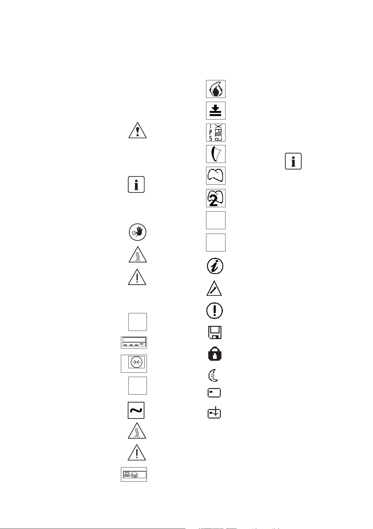
Risks and dangers
This symbol marks
safety instructions that
must be followed to
prevent injury or death.
Furthermore, damage to the
furnace and/or laboratory may
be avoided.
Important information
This symbol marks
additional information
for correct and
economic use of the
EP600 Combi.
Contraindication
Burn hazard
Risk of crushing
Furnace
Printer
Fuses
Vacuum
K-Module
(Communication
module)
Alternating current
(IEC 417)
Burn hazard
(IEC 417)
Risk of crushing
Outlet
(SELV, max. 24 VDC/A1)
PC printer connection
Display
FIRING Mode
PRESSING Mode
IPS e.max
IPS Empress Esthetic
IPS Empress
Layering Technique
IPS Empress 2
Layering Technique
IPS Empress Cosmo
IPS Empress
Staining Technique
Note
Technical malfunction
Operating error
Saving active; do not
switch off the furnace
Timer active,
programs cannot be
started
Energy-saving mode
active
Program memory card
active
Data transfer from/to
Program memory card
active
1.3 Notes regarding the
Operating Instructions
These Operating Instructions
facilitate the correct, safe, and
economic use of the EP600
Combi Press and Ceramic
Furnace. They are divided into
several, clearly structured
chapters. This should enable you
to locate specific topics quickly
and easily.
You must read these
Operating Instructions
To inform you about risks,
dangers, important information,
and contraindications, these
Instructions contain corresponding signs/symbols to mark
important paragraphs.
We recommend keeping the
Instructions in a safe place near
the furnace to have immediate
access to the information if
necessary.
Should you lose the Operating
Instructions, extra copies can be
ordered at a normal fee from
your local Ivoclar Vivadent
Service Center.
Furnace concerned:
EP600 Combi Press
and Ceramic Furnace
Target group:
Dental technicians
and technologists
1. Introduction / Signs and Symbols
V ~ 110-120
A max. 2.1
Ableitstrom / Leakage current
max. 0.75 mA
250VAC
T5A T12A T2A
RS 232
Page 9
2. Safety First
This chapter is especially important for individuals
who work with the EP600 Combi or who have to
carry out maintenance or repair work. This chapter
must be read and the corresponding instructions
followed!
2.1 Indications
The EP600 Combi has been designed for pressing
IPS e.max and IPS Empress ingots and for firing
dental ceramic materials and should be used for
these purposes only. Uses other than the ones
stipulated, e.g. cooking of food, firing of other
materials, etc., are contraindicated. The manufacturer does not assume any liability for damage
resulting from misuse. The user is solely responsible for any risk resulting from failure to observe
these instructions.
Further instructions to assure
proper use of the furnace:
– The instructions, regulations,
and notes in these Operating
Instructions must be observed.
– The instructions, regulations,
and notes in the vacuum
pump Operating Instructions
must be observed.
– The furnace must be operated
under the indicated environmental and operating
conditions (see Chapter 9)
– The EP600 Combi must be
properly maintained.
2.1.1
Risks and dangers
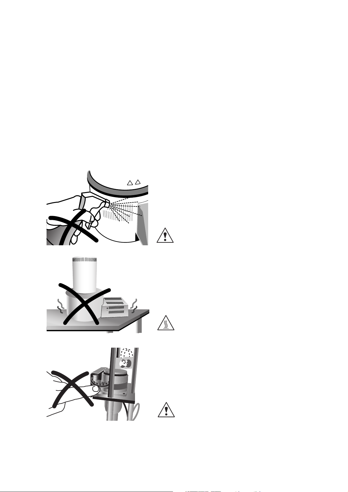
Make sure that no liquids or
other foreign objects enter the
furnace or the air vents, since
this may result in an electrical
shock.
2.1.2
Burn hazard
The furnace head should not be
removed from the furnace and
placed on a working surface or
packaging material while it is
still hot, as there is a burn
hazard.
2.1.3
Risks and dangers
Never touch the electronic
components, since a static
discharge may damage them.
9
Page 10
10
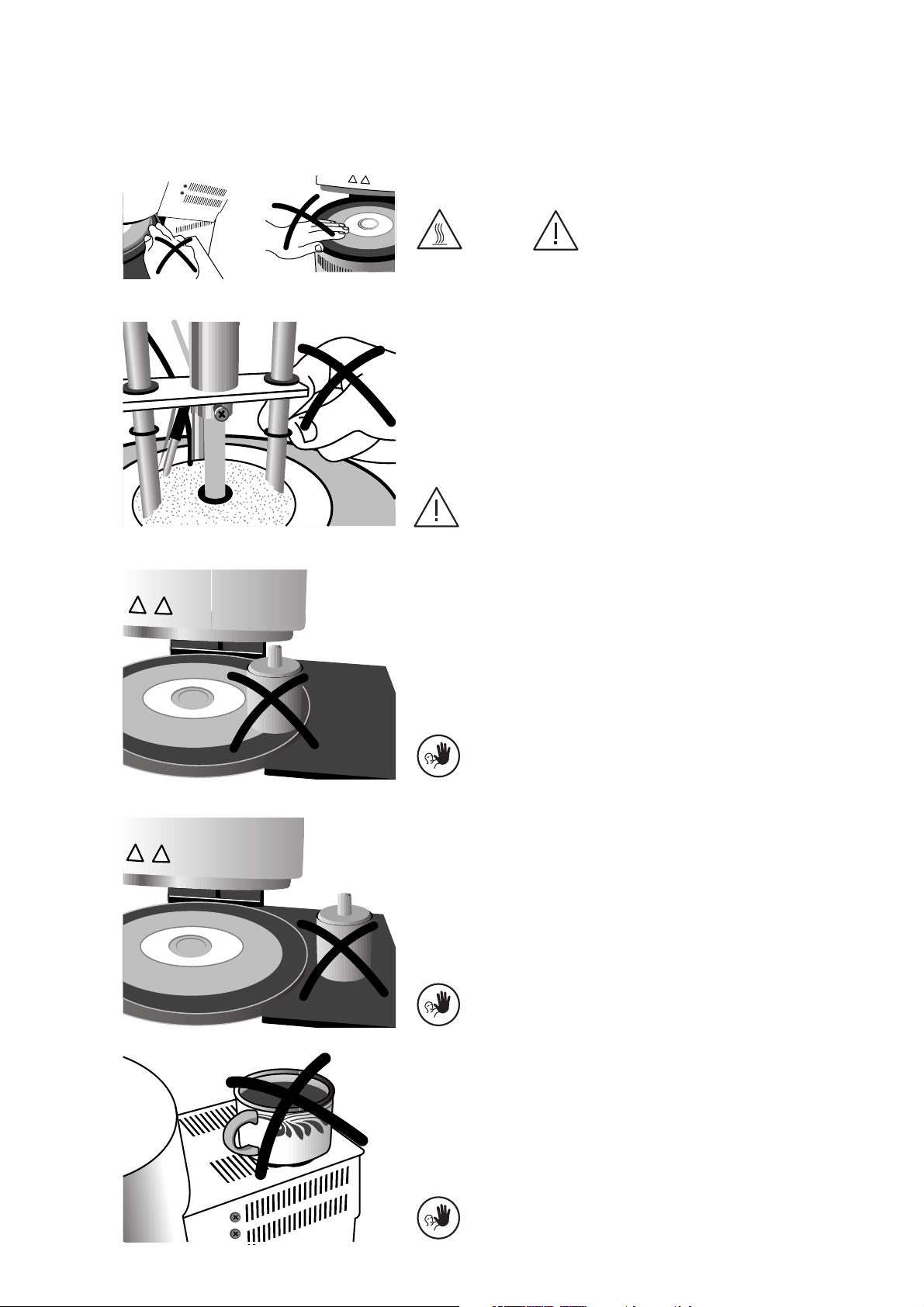
2.1.4
Risk of crushing / burn hazard
Never reach under the furnace
head during operation. There is
a risk of crushing and a burn
hazard.
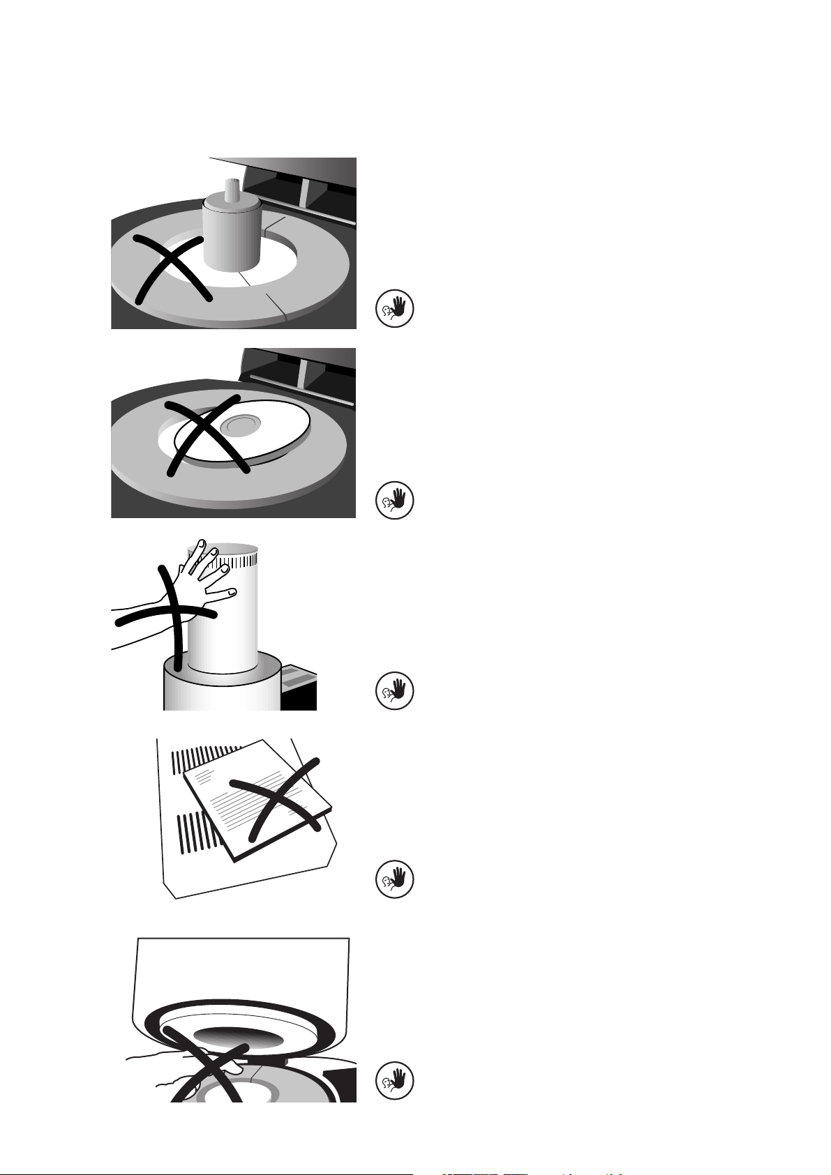
2.1.6
Contraindication
2.1.7
Contraindication
Investment rings or firing trays
must not be placed in the area
surrounding the firing table,
since they may get stuck under
the furnace head. Use the
sagger tray for firing trays or the
cooling grid for fired investment
rings.
2.1.8
Contraindication
Do not place any objects on the
furnace head. The opening
process of the furnace head
must not be obstructed.
Fired investment rings must not
be placed on the sagger tray to
cool. Please use the cooling grid
especially designed for that
purpose.
2.1.5
Risk of crushing
Never touch the press drive
during operation. There is a risk
of crushing.
Page 11
11
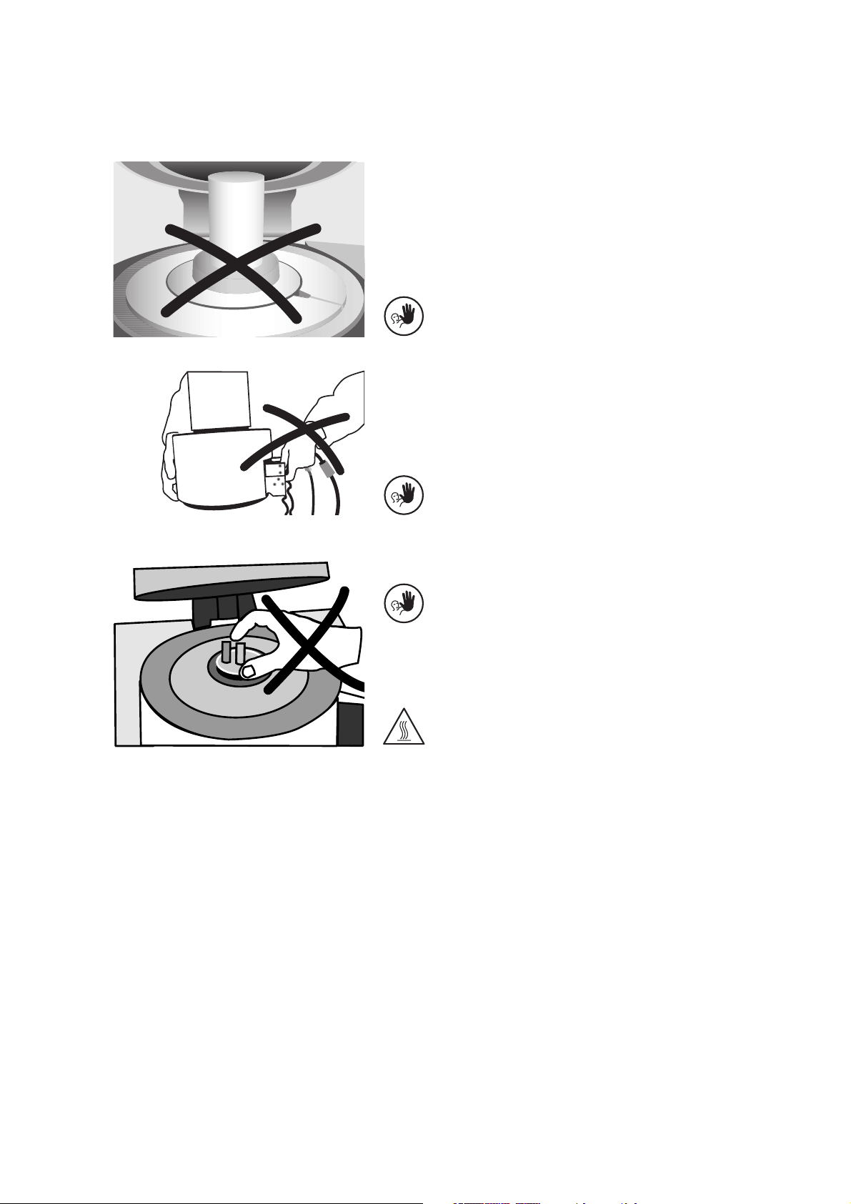
2.1.9
Contraindication
Press cycles must not be
conducted without the firing
plate (50) in place.
2.1.10
Contraindication
The firing plate (50) must be
correctly positioned in the firing
chamber.
2.1.11
Contraindication
The furnace head is equipped
with an electronic drive and
must be operated with the
corresponding keys. Never open
or close the furnace head
manually.
2.1.12
Contraindication
The air vents must be kept free
from obstruction and clean at all
times. If this is not done, there is
a risk of overheating the
furnace.
2.1.13
Contraindication
Do not bend the thermocouple
(71). Do not touch the thermocouple with your fingers in order
to prevent contamination
(grease).
Page 12
12
2.1.15
Contraindication
The furnace head must not be
carried by holding the cables, as
there is a risk of damaging the
cables and the corresponding
connections.
2.1.14
Contraindication
If the firing tray (150) is in
place, press cycles must not
be conducted.
2.1.16
Contraindication
Burn hazard
Never place objects into the
firing chamber with your bare
hands. Always use the
corresponding tongs of
Ivoclar Vivadent supplied for
that purpose.
Do not touch the surfaces of the
furnace head while it is hot.
There is a burn hazard.
Page 13

13
2.2 Health and safety
instructions
This furnace has been designed
according to EN 61010-1 and
has been shipped from the
manufacturer in safe operating
condition. To maintain this
condition and to ensure risk-free
operation, the user must observe
the notes and warnings in these
Operating Instructions.
– Place furnace on a fire-proof
table, observe local regulation
(e.g. distance to combustible
objects, etc.).
– Always keep the air vents at
the rear of the furnace free
from obstruction.
– Do not touch any parts that
become hot during operation
of the furnace.
There is a burn hazard.
– Clean furnace only with a dry
or slightly damp cloth. Do
not use any solvents.
Disconnect power before
cleaning.
– Use original packaging for
transportation purposes.
– It is important that the user
become familiar with the
warnings and operating
conditions to prevent injury
to personnel or damage to
materials. The manufacturer
is not responsible for damage
resulting from misuse or failure to observe the Operating
Instructions. Warranty claims
cannot be accepted in such
cases.
– Before switching on the
furnace, make sure that the
voltage indicated on the
rating plate complies with
the local power supply.
– The mains socket must be
equipped with a residual
current operated device (FI)
– The power plug may only be
inserted into sockets with
protected contacts.
– Before calibration, main-
tenance, repair, or change of
parts, the power must be
disconnected if the furnace
has to be opened.
– If calibration, maintenance,
or repair has to be carried
out with the power connected
and furnace open, only
qualified personnel, who are
familiar with the risks and
dangers, may perform the
procedures.
– After maintenance, the
required safety tests (high
voltage resistance, protective
conductor, etc.) must be
carried out.
– Ensure that only fuses of the
indicated type and current
rating are used.
– If it is assumed that safe
operation is no longer
possible, the power must be
disconnected to avoid
accidental operation.
Safe operation is no longer
possible if:
– the furnace is visibly
damaged
– the furnace does not work
– the furnace has been
stored under unfavourable
conditions over an
extended period of time
– Use only original spare parts.
– The temperature range for
faultless operation is +5 °C
to + 40 °C (41 °F to 104 °F).
– If the furnace has been stored
at very low temperature or
high atmospheric humidity,
the unit must be dried or left
to adjust to the room
temperature for approx.
1 hour prior to connecting
power.
– The furnace is tested for use
at altitudes of up to 4000 m
(13,123 ft) above sea level.
– The furnace may only be
used indoors.
Risks and dangers
Do not work with
liquids near the
furnace. Should a
liquid accidentally enter the
furnace, disconnect power and
consult the Customer Service.
Do not operate the furnace.
Risks and dangers
Any disruption of the
protective conductor
either inside or outside
the furnace or any loosening of
the protective conductor may
lead to danger for the user in
case of a malfunction. Deliberate
interruptions are not tolerated.
Material developing harmful
gases must not be fired.
Page 14

14
3. Product Description
3.1 Components
The EP600 Combi Press and
Ceramic Furnace comprises the
following components:
– Furnace base with electronic
controls
– Furnace head with press
drive
– Sagger tray
– Vacuum hose
– Vacuum pump with hose
and power cord (accessories)
The electronic controls and the
mechanical components for the
opening mechanism are located
in the furnace base. The heater
is located in the muffle in the
furnace head, where it is
embedded in the stone lining
segments. Operation and control
of the furnace is done with
state-of-the-art electronic
components.
Hazardous area Type of risk
Press and firing chamber Risk of burning
Opening/closing mechanism Risk of crushing
Electronic components Risk of electrical shock
Safety equipment Protective effect
Protective conductor Protection from electrical shock
Fuses Protection from electrical shock and damage to
the furnace
Interlock switch Protection from electrical shock
3.3 Functional description
The press/firing chamber may be heated up to
max. 1200 °C (2192 °F) by means of a heater.
Furthermore, the chamber is designed so that a
vacuum can be created with a vacuum pump.
The press drive produces the pressure required
for the press procedure. The press process is
controlled by means of the electronic components
and the corresponding software.
3.4 Accessories
– Refill Package ATK 1 "Melting Samples"
– Refill Package ATK 1 "Ceramic Base Blocks,
Contact Pins"
– Vacuum pump
3.2 Hazardous areas and
safety equipment
Description of the hazardous areas of the furnace:
Description of the safety equipment of the
furnace:
Please also refer to Chapter 2.
Page 15

15
4.1 Unpacking and
checking the contents
The new packaging provides the
following advantages:
– Reusable packaging
– Closing mechanism with inte-
grated transportation grips
– Ideal protection by Styrofoam
inserts
– Easy handling / optimum
unpacking
– The packaging may be used
in several ways (modules)
Check the delivery for completeness (see delivery form in
Chapter 9) and transportation
damage. If parts are damaged
or missing, contact your local
Ivoclar Vivadent Service Center.
Remove the furnace components
from their packaging and place
the unit on a suitable table.
Please observe the instructions
on the outer packaging.
There are no special transportation grips on the furnace.
Support the bottom of the
furnace to carry it.
Packing and shipping of
individual components
The packaging of the
EP600 Combi permits simple
and safe shipping of individual
components. Simply use the two
corresponding inserts. Fold the
side flaps (2) and combine the
two packaging parts by means
of the transportation flaps.
The packaging may be discarded
with the regular household
refuse.
Important information
We recommend
keeping the original
packaging for future
transportation purposes. The
unit has been subjected to
extensive checks by the manufacturer. It may therefore exhibit
slight signs of testing (hairline
cracks, slight discoloration).
4.2 Selecting the location
Place the furnace on a flat table
using the rubber feet. Make sure
that the furnace is not placed in
the immediate vicinity of heaters
or other sources of heat.
Furthermore, protect the furnace
from direct sunlight. Make sure
that air may properly circulate
between the wall and the
furnace.
Also ensure that there is enough
space between the furnace and
the user, as the furnace releases
heat during the opening of the
furnace head.
The furnace should neither be
placed nor operated in areas
where there is an explosion
hazard.
4.3 Assembly and initial
start-up
Make sure the voltage indicated
on the rating plate complies
with the local power supply. If
this is not the case, the furnace
must not be connected.
4. Installation and Initial Start-Up
Page 16

16
The furnace components are
assembled as follows:
Step 1:
Assembling the tray and the
firing plate
– Mount the supports for the
sagger tray (25)
– The sagger tray (1) is slipped
onto the screws (2). If
desired, the screws may be
tightened using a screwdriver.
– Remove the firing plate (50)
from the protective paper
and place it in the stone
lining.
– Clean the sealing surface
(19).
Step 2:
Assembling the furnace head
The furnace head is best
assembled with the rear of the
furnace base placed as shown in
the corresponding figure. Lift
the furnace head with both
hands and slip the plug-on
console (77) onto the
corresponding pegs (75) in the
furnace base until the leaf spring
(76) audibly snaps into place.
Please make sure that
no cable is caught
between the furnace
head and the furnace
base and that the red
marks are lined up.
Step 3:
Mounting the connections
– Connect the cables of the
furnace head with the
furnace base.
– Insert the heater plug (66)
into the heater socket (17)
and secure it with the
retention screw (67) with a
right-hand turn.
– Insert the thermocouple plug
(64) into the thermocouple
socket (18).
– Make sure the polarity of the
plug is correct (+ signs
together).
– Insert the press drive plug
(65) into the press drive
sockets (16) until it audibly
snaps into place.
– Mount the grounding band
(78) of the furnace head
onto the sip-on tongue of
the furnace base (23).
2
77
75
76
66
64
18
65
16
23
78
67
17
1
25
1
Page 17

17
Step 6:
Setting-up the cooling grid for
investment rings
The cooling grid for investment
rings is supplied fully assembled.
Please position the grid in a
suitable place.
Please remember that
the investment rings
are very hot and that
the grid should not be
placed on combustible
surfaces or in the
vicinity of combustible
objects and materials.
Step 4:
Mounting the furnace head
connections cover
Once the connections between
the furnace head and the
furnace base are established,
assemble the furnace head
connections cover (54) and
secure it with the corresponding
screws (51).
Step 5:
Establishing additional
connections
Make sure the voltage indicated
on the rating plate of the
apparatus complies with the
local power supply. If everything
is in order, plug the power cord
(21) into the power socket (6).
Vacuum pump
Insert the plug of the vacuum
pump into the socket for the
vacuum pump (7) and slide the
vacuum hose onto the vacuum
hose connection (12).
We recommend using
the Ivoclar Vivadent
VP3 Vacuum Pump
with this furnace.
If another pump is used, the
maximum power consumption
and the maximum final vacuum
of the corresponding pump have
to be observed.
54
12
14
6
21
7
12
79
Page 18

18
Step 7:
Connecting the card reader
Connect the adapter (165) with
the RS232 PC/Printer interface
(14) and insert the plug (161) or
the card reader (Type 'ECO 5000
KB1' from ORGA) into the
adapter.
Important information
Please make sure that
the voltage indicated
on the rating plate
complies with the local power
supply. You may only use the
apparatus if the voltage is
compatible.
If the apparatus has been
correctly connected and is ready
for operation, the status
indicator (163) lights up.
Program parameters may be
stored on and read from a
memory card using the card
reader.
Firing programs stored on the
memory card are used in the
same way as the ones stored in
the furnace. They may be
accessed, edited, and run.
Insert the program memory card
into the card reader with the
microchip facing downwards.
The storage system is now ready
for operation.
Chapter 5 (Program Manager)
describes how to copy programs
to and from the program
memory card.
In order to activate the
card reader, "Eco
5000" has to be set as
output device in the
menu "Miscellaneous –
Configuration – Interface".
See also Chapter 5.4.4
The RS232 interface (14) may
also be used to connect a printer
or a PC in order to save or print
firing protocols.
procedures. As a result, the
firing chamber may exhibit slight
signs of testing. These signs
show that the unit has been
tested. These checks are
important for quality assurance.
Disassembling the furnace head
Note: Before the furnace head
connections cover is removed,
the furnace should be switched
off and the power cord (21)
unplugged.
Removing the furnace head
connections cover
– Remove screws (51) of the
furnace head connections
cover.
– Remove the furnace head
connections cover (54)
Removing the secured furnace
head
– Before the furnace head is
removed, the heater plug,
thermocouple plug, press
drive plug, and grounding
band should be disconnected
from the furnace base.
– Release leaf spring (76) and
lift off furnace head using
both hands.
Initial start-up
Connect the power cord (21)
with the power supply. Put the
On/Off switch (5) at the rear of
the furnace on position "I".
The language selection menu
appears on the display. Select
the language by means of the
F4 key and confirm by pressing
ENTER. Complete the selection
procedure using the function
key F1. After selecting the
language, the display shows the
EP600 logo. After that, the unit
conducts a self-test to check the
basic functions. The course of
the self-test is indicated by
means of a status bar. Once the
self-test has been completed
successfully, the preheating
phase will start. This phase
prepares the unit for optimum
temperature control. The
self-test and preheating phase
together usually take 30 min.
To reduce the moisture
in the press chamber
(stone lining) the
vacuum pump is
switched on during the preheating phase, thus removing
the moist air.
As of Software Version V3.0 the
vacuum pump is kept on during
the complete pre-heating phase.
Once the preheating phase has
been completed, the unit is
ready for operation.
The 'furnace selection' menu is
displayed to select whether the
furnace is used as a ceramic or
press furnace. After that, the
main menu appears on the
display.
Important information
During the test of the
press drive, noise from
the press drive is
audible (approx. 2 seconds).
During the self-test, this sound is
normal. If this is not the case, a
technicalmalfunctionhas occurred.
Please refer to Chapter 8.
The power plug may
only be inserted into a
grounded socket. The
power cord must not
come into contact with the hot
furnace head and should be
protected accordingly.
The EP600 Combi is
equipped with a
special electronic
device that can bridge
a power outage of approx.
10 seconds.
The EP600 Combi
Press and Ceramic
Furnace undergoes
extensive checks prior
to delivery. In the process, the
unit is subjected to special test
164
163
160
14
165
161
Page 19

19
5.1 Starting the furnace
5.1.1 Start-up
After the furnace has been switched on, the
unit undergoes a self-test, and if necessary, a
preheating cycle. The furnace selection
menu is shown on the display.
To reduce the moisture in the press
chamber (stone lining) the vacuum
pump is switched on during the
pre-heating phase, thus removing
the moist air.
As of Software Version V3.0 the vacuum
pump is kept on during the complete preheating phase.
5.1.2 Main menu
In this menu, you may select whether the
EP600 Combi is used as a press furnace or a
ceramic furnace. The 'Combi Furnace'
software is required for the latter option.
Additionally, the menu item "Miscellaneous"
can be accessed from here. This menu
automatically appears, once the preheating
cycle has been completed.
5.2 Introduction to the
operation "Pressing"
The EP600 Combi is designed for use with
the Ivoclar Vivadent all-ceramic systems
IPS e.max and IPS Empress. Therefore, the
corresponding parameters of the various
programs have already been set in the
factory. All you have to do is select the
desired program for the corresponding
material using the function keys F1 (104), F2
(105), F3 (106), or F4 (107). Next select
whether you are using a large or small
investment ring. After that, the display
indicates the corresponding program cycle
diagram. The program is started by pressing
START. The firing of the press cycle selected
is graphically displayed. The most important
parameters are visible on the display (74) at
all times.
5.2.1 Main menu "Pressing"
This menu appears after selection of the
menu item "Press furnace" in the main
menu.
Page 1
Page 2
Page 3
Page 4
Now the press program is selected using the
function keys. This menu always displays
three programs, which may be selected by
means of the function keys F1, F2, and F3.
The menu comprises several pages. F4 is
used to move forward.
On the last page, there is an option called
"Main menu".
5.2.2 Menu "Investment ring selection"
This menu is used to indicate which
investment ring (large, small) will be used.
5.2.3 Menu "Program"
In this menu, a graphical representation of
the currently selected program is displayed.
The temperature curve indicates the set
temperature values. The progress of the
running program is shown by a bold line.
The remaining time until the start of the
actual press process is also indicated. As
soon as the press process has commenced,
the time passed since the beginning of the
press process is indicated.
Furthermore, the display indicates the
distance travelled by the press plunger in the
selected unit of measure since the beginning
of the press process, as well as the quality of
the vacuum in percent. If no program is in
progress, F2 and F3 can be used to change
between the various programs.
With F4, the parameters of the currently
selected program can be viewed (see menu
"Program parameters").
5.2.4 Menu "Program parameters"
In this menu, the set parameters of the
selected program are displayed or edited
(for freely programmable programs).
Pressing F1 returns you to the menu
"Program".
5. Operation and Standard Settings
Page 20

Please use only the original
standard programs, which are
especially coordinated with the
corresponding materials for the
Ivoclar Vivadent all-ceramic
systems (IPS e.max, IPS Empress
System).
20
Freely programmable press programs
Furthermore, the EP600 Combi is equipped
with 4 freely programmable press programs
(P8–P11). For these programs, values within
the following ranges can be entered:
Important information
For the layering technique, we
recommend a stop speed of
300 mm/min, for the staining
technique 150 mm/min.
– Higher values (stop speed of e.g.
300 mm/min) results in the press cycle
being stopped sooner.
– Lower values (stop speed of e.g.
100 mm/min) results in the press cycle
being stopped later. Consequently, the
press cycle is prolonged.
Once the program is started by pressing
START, the new program is displayed in the
usual manner.
5.3 Introduction to the
operation "Firing"
5.3.1 Main menu "Firing"
The main menu "Firing" always displays
menu items, which may be selected by
means of the function keys F1, F2, and F3.
The menu comprises several pages. F4 is
used to move forward.
Menu without program memory card in
place:
Page 1
Menu with program memory card in place:
Page 1
Page 2
Parameter
B Stand-by temperature
t Temperature increase
T Holding temperature
H Holding time
E Stop speed
MIN
50
1
50
0
0
MAX
900
140
1200
109
1000
Unit of measure
°C
°C/min.
°C
min.
µm/min
Page 21

21
Internal programs
With this menu item, you may access
50 individual firing programs that are
stored in the furnace.
Program memory card
This option also provides 50 individual
programs. However, the programs are stored
on the program memory card by means of
the card reader. This option may only be
selected if a program memory card is present
in the card reader.
Program Manager
This menu item offers you various copying
options. For example, programs from the
furnace may be saved on the program
memory card.
Main menu
This menu item allows you to return to the
main menu.
5.3.2 Firing program groups
The program groups are used to organize
the 50 firing programs in five groups each
consisting of 10 programs. You may name
the groups, e.g. according to the materials
used (e.g. d.SIGN), according to the name of
the technician (e.g. John Miller), or according to your own requirements. These
program groups can be found in the internal
memory or the program memory cards.
Use F1 to return to the next higher level.
Use F2 to select a program group. After
that, F3 is pressed to reach the menu "Text
input". The names of the groups can be
freely defined. Twenty characters are
available for that purpose (see "Text input").
Use F4 to open the program list of the
current group.
Text input
The characters are selected using F2 and F3.
Use F4 to transfer the selected, highlighted
character to the text field. A character can
be deleted from the text field with F1.
Additionally, the numerical keys 2, 4, 6, and
8 may be used to navigate the characters.
In order to leave the text input screen and to
confirm the defined text, press ENTER. If you
want to leave the text input screen without
acknowledging the text, press ESC.
List of firing programs
The list of firing programs shows all the
firing programs (10 programs) of a program
group. The program group may be stored in
the internal memory of the furnace or on a
program memory card.
Use F2 to select the desired program. Once a
program has been selected, F3 is used to
access the text input screen. The names of
the groups can be freely defined. Twenty
characters are available for that purpose.
Enter the desired text as described above.
The date (e.g. 01.01.99) of the latest change
or saving will be automatically allocated to
the program. Use F1 to return to the menu
"Firing program groups". Use F4 to access
the firing curve display.
Once the firing curve display is visible, press
START (110) to start the selected program.
Important information
If no vacuum is set, i.e. no values for V(A) or
V(B), the vacuum bar is replaced by the text
"No vacuum".
Use F1 to change to the list of firing
programs.
Press F2 to return to the previous firing
program or F3 to change to the next firing
program.
Use F4 to return to page 1 of the program
parameters menu.
Once the firing curve display is visible, press
START (110) to start the selected program.
Program parameters, Page 1
The furnace is supplied by the factory with
50 free programs (empty parameters). The
parameters of the firing program may be set
on 2 menu pages.
The parameters for standard firing programs
are listed on page 1, while page 2 contains
the additional parameters necessary for
special programs.
The header displays the name of the
program group (e.g. d.SIGN), program
number (1), program name (glaze firing),
and the current temperature (403 °C).
Use F2 and F3 to change from one
parameter to the next or the previous one.
F1 is used to change to the firing curve
display. Once the firing curve display is
visible, the selected program is started by
pressing START.
The values are displayed in the form of a
table and may be individually set by the user.
The values entered have to be confirmed
with ENTER.
Page 22

22
Important note
Vacuum:
If the value 0 is entered for V1 and V2,
no vacuum will be created.
Long-term cooling
Values between 50 and 1200 °C (122 and
2192 °F) may be entered. If 0 is entered, no
long-term cooling will be conducted.
Special programs
If "No" has been selected in the "Special
program" option, Page 2 of the program
parameters cannot be accessed.
If "Yes" is selected (press F4, "yes" appears,
confirm with ENTER), Page 2 is opened to
set the special values.
Program parameters, Page 2
Use F2 and F3 to change from one
parameter to the next or the previous one.
F1 is used to change to the firing curve
display. Once the firing curve display is
visible, the selected program is started by
pressing START.
Additional information regarding the special
programs
HV: Share of holding time with vacuum
With the parameter HV, the user selects if
and when the vacuum is switched off during
the holding time H.
– If V2 < T, the vacuum is switched off
before the holding temperature is
reached. In such cases, the parameter
HV is irrelevant.
– If V2 >= T, the parameter HV is taken
into consideration.
– If HV = 0, the vacuum is not switched
off during the holding time.
– If HV > 0, the vacuum is switched off
after period HV has passed since the
beginning of the holding time, but at the
end of the holding time H at the latest.
Use of HV for the first or second holding time
– For one-step programs, HV is used for
the first holding time H(A).
– For two-step programs, HV is used for
the second holding time H(B). For the
first holding time, the following rule
applies: If V2(A) ≥ T(A), the vacuum is on
during the entire first holding time.
SO: Quick opening
If this option is switched off, the furnace
head opens within one minute after the end
of the program. If this option is switched on,
the furnace head opens within 15 seconds
after the end of the program.
NP: Overnight program
This option corresponds to the one offered
by the Programat P100 and Programat X1
furnaces. If this option is switched off, the
furnace head opens after the end of a firing
program. If this option is switched on, the
procedure is as follows:
– The firing program is completed, the
heater is switched off.
– The furnace head opens without the
buzzer sounding.
– Once the furnace temperature drops
below 150 °C (302 °F), the furnace head
closes. The heater remains off.
Program course
Programs in progress can be stopped by
pressing STOP. An interruption of the
programs is not possible.
Empty programs
Upon delivery, all the internal firing program
spaces are filled with 'empty' programs. An
empty firing program does not have a name.
Empty programs are treated like any other
program. They can be selected, run, or
edited:
Holding temperature 700 °C
Temperature increase 30 °C/min.
Closing time 18 seconds
Stand-by temperature 403 °C
Holding time 1 minute
Vacuum on / Vacuum off both 0
(i.e. no vacuum)
Long-term cooling none
Special program no
5.3.3 Main menu "Program manager"
This program permits copying of the firing
programs to various storage media (EP600
program memory, or program memory card).
Example:
– Copy "Program" from "Internal
programs" No. 23 to "Program" on
"Memory card" No. 24
Duplicating programs: If the source and
target media are identical, the program on
this medium is duplicated.
Since copying always results in an existing
program being overwritten (possibly an
empty program), the following inquiry will
be shown:
This inquiry should prevent the programs
from being overwritten accidentally.
Important information:
Only firing programs can be copied.
Press programs cannot be copied.
Page 23

23
5.4 Introduction to the menu
"Miscellaneous"
This menu is called up via the main menu.
It permits the selection of a number of
lower-level programs with which the furnace
can be configured, calibrated, tested, etc.
5.4.1 Menu "Furnace information"
(Example)
Serial number of the furnace: 00001234
Article number of the furnace: 00006789
Number of press cycles: 789
Number of operating hours: 1245 h
Number of firing hours: 789 h
Operating hours of the vacuum pump: 367 h
Software date: 14.06.00
Version of the operating software: V01.00
Version of the supply board software: V01.00
Version of the press drive software: V01.00
5.4.2 Menu "Calibration"
This menu provides an auto-calibration
program. The temperature measuring circuit
can only be calibrated with this program.
The data of the latest ten calibrations are
stored in a table according to the date and
time (see menu "Protocols").
5.4.3 Menu "Diagnostic programs"
In this menu, the user is provided with
various diagnostic programs (see Chapter
7.4 "Diagnostic programs").
5.4.4 Menu "Interface"
With the help of this menu, the RS232
interface can be configured.
– Baud rate
Defines the transmission rate.
– Parity
Defines the number of bits transmitted
per character.
– Stop bits
Defines for which number of bits the line
has to be idle before the next character is
transmitted.
– Output device
Selection of the type of device connected
with the EP600 Combi.
– Code page
Character set
Parameters for the card reader
Baud rate = 9600
Data bits = 8
Parity = even
Stop bits = 1
Output device = ECO5000
Code page = CP 437
5.4.5 Menu "Configuration"
In this menu, the following functions of the
furnace can be configured:
Page 1
– Furnace type
This option is used to select the desired
furnace type: EP600 or EP600 Combi.
To change the furnace type, a code is
required, which has to be entered after
the selection of the new furnace type.
– Language
German, English, French, Italian, Spanish.
Further languages possible at a later
date.
– Default settings
If this option is selected and confirmed
with ENTER, all the subsequent menu
items are set to the default settings.
– Date format
With this menu item, the date format
may be changed from the European to
the American format and vice versa.
– Date
With this menu item, the exact date can
be set.
– Day
With this menu item, the day can be set.
– Time
With this menu item, the exact time can
be set.
– Temperature mode
With this option, the temperature may
be changed from °C to °F and vice versa.
– Vacuum unit of measure
With this option, the unit of measure for
the vacuum (mbar, hPa) can be selected
and/or changed.
– Measure of length
With this menu item, the measure of
length (mm, inch) can be selected and/or
changed.
Page 2
– Vacuum quality 100 %
This option indicates the absolute value
(in mbar) for 100 % vacuum quality.
– Return to "Main menu"
With this option, it may be determined
whether the software returns to the "Main
menu" once a program is completed or
if the current menu is maintained.
– Energy saving mode
If the energy saving mode is active, the
heat is reduced after a time period defined
by the user. In this way, the life cycle of
the heating muffle is prolonged and energy
is saved. By pressing the indicated function
key, the mode may be deactivated.
– Time of energy saving mode
Period of time after which the energy
saving mode is activated if no program is
in progress and no key has been touched.
– Acoustic signal
On/Off
– Pitch of the signal
Tune 1–9
– Volume of the signal
Three stages: low, medium, loud
– Signal at the beginning of the press
process
Yes/No
– User mode
This menu option is reserved for Service
Centers.
– Press drive calibration value
Page 3
– Protocols active
No / Yes / Direct
No –> Press/Firing programs are not
protocolled.
Yes –> Press/Firing programs are
protocolled (Press/Firing program
protocol table). The protocols have to
be transmitted manually from the
corresponding protocol table)!
Page 24

24
Direct –>Press/Firing programs are
protocolled (Press/ Firing program
protocol table) and are shown or printed
immediately on the serial interface
RS232. Please note that therefore, a
corresponding output device (printer or
PC) has to be selected in the menu
'Interface'.
– Pager 1
Yes/No
– Laboratory name
Name which will appear in the header
or footer of the various protocols.
5.4.6 Menu "Maintenance"
This menu provides the commands necessary
during the maintenance of the furnace.
– Lower press plunger manually
– Lift press plunger manually
5.4.7 Menu "Enter new program"
The "Main menu pressing" also provides
three individual programs (Program No. 5–7)
in addition to the standard programs. If
these programs are not shown in the menu,
they are still concealed. They can be inserted
using the following function:
To insert one of the programs (program No.
5–7), select this menu item (F4), type in the
correct code, and confirm with ENTER.
Code Program No.
14000 5
15000 6
16000 7
If the code was typed in correctly, the "Main
menu pressing" displays the new program.
By therein entering the code, a
concealed program will be released
and an already released program
will be concealed.
5.4.8 Menu "Request alarm table"
See Chapter 7.3.
5.4.9 Menu "Protocols"
After selecting this menu the table with the
calibration data is shown.
Key F4 can be used to switch to the press
program protocol table (keys to be pressed:
F4, ENTER).
In this table the protocols of the last
15 press programs are stored. These
protocols can be transmitted manually from
here to the PC or printer (this depends on
the settings in the menu ‘Interface').
Key F4 can be used to switch to the firing
program protocol table (keys to be pressed:
F4, ENTER).
In this table the protocols of the last
15 firing programs are stored. These
protocols can be transmitted manually from
here to the PC or printer (this depends on
the settings in the menu ‘Interface').
5.4.10 Menu "Timer"
In this menu, the timer may be programmed.
With this feature, the furnace may be
heated up to stand-by temperature or
switched off at any given time.
In the interval between the switch-on and
the switch-off times, the unit is kept at
stand-by temperature.
To change the setting, select the
corresponding switch-on/switch/off time
with the cursor (F2/F3) and use the numeric
keypad for selecting the desired time.
The timer can also be switched on or off
with the key ‘timer active-yes/no’.
The times are typically typed in via the
numeric keypad. F3 is used to change the
selected menu item. ESC is used to undo
changes. ENTER is used to save the changes.
The mains switch must not be switched off
during this procedure.
When the timer is active, i.e. when
the heater is switched off, the
symbol is shown on the display. If
a program has not been completely
finished at the time when the furnace is
scheduled to turn off, the program will
nonetheless be completed before the heater
is deactivated. While the timer is active,
programs can only be started once the time
settings have been adjusted accordingly.
5.4.11 Menu "Status memory card"
In this menu, all the information regarding
the status of the card reader and the
memory card in the card reader can be
accessed.
Page 25

25
5.5 Operating the menu /
key functions
5.5.1 Navigation
1
2
3
1 Information line
This line always shows the most current
temperature and operating mode.
Additionally, useful program information is
displayed.
2 Firing curve and dialog field
In this field, the dialogues and the various
information are displayed. The different
parameters may be changed here.
3 Function line
Change of level
1 level higher
Selector up
Selection within the same level
Selector down
Selection within the same level
Change of level
1 level lower
Selection key
Selection from various possibilities
The selection must always be confirmed
with ENTER.
The four function keys below the display are
used to navigate through the various menus.
The functions of the keys are represented by
symbols. These symbols are shown for those
keys, which have a certain function at the
current stage in the program. For example,
the symbol for the 'page down' key is only
shown if the contents of the current screen
take up more than one page.
5.5.2 Numeric keypad
The numeric keypad is used to enter
numbers. This keypad also contains the ESC
and ENTER keys.
5.5.3 Text input
The input of text is enabled by a virtual
keyboard shown on the display. F2 and F3
are used to select the characters. F4
transfers the selected, highlighted character
to the text field. F1 can be used to delete a
character from the text field. ENTER is used
to leave the text field and confirm the text.
If the user wants to quit this menu without
confirming the text, ESC is used.
5.5.4 Numbering of the various menus
To facilitate support, each menu is given a
number, which will become visible as soon
as the help function of the menu in question
is called up.
5.5.5 Display contrast
The display contrast can be regulated by
means of key 101.
If the unit has been in operation
for an extended period of time,
the display contrast properties may
change due to an increase in
temperature.
5.6 Help function
Pressing HELP will display a help text for the
current menu.
If the help text consists of several pages, the
'Up' (F2) and 'Down' (F3) symbols are
shown. They indicate that these keys may be
used to navigate between the individual
pages. F1 is used to return to the last active
menu.
5.7 Protocolling /
Output of protocols
From the press/firing program protocol
charts the protocols saved there can be
output. For that reason use key F2 to set the
cursor on position 'Print'. Subsequently,
enter the position number of the protocol to
be printed with the numbers’ block and
confirm with the ENTER key. Using key F4
the selected protocol can be sent via the
serial interface RS232 to the printer or PC
(Prograsoft).
Example press program protocol table:
Example firing program protocol table:
ESC:
Discarding values
ENTER: Used to confirm
entered numbers, for
example, or the change
of the temperature mode
from °C to °F.
Page 26

26
6.1 Switching on/off
Put the I/O switch at the rear of the furnace
on position "I". The furnace is now switched
on and the EP600 logo appears on the
display. Subsequently, the unit conducts a
self-test to check the basic functions. The
course of the self-test is shown by means of
a status bar. If the self-test does not reveal
any errors or malfunctions, the preheating
phase is started. The preheating phase
prepares the furnace for optimum
temperature control. The self-test and
preheating phase together take 30 minutes.
After the preheating cycle has been
completed, the unit is ready for operation.
The main menu appears.
Important information
If the temperature in the firing
chamber is above 300 °C (572 °F)
at the time when the furnace is
switched on, only a self-test is
conducted. The preheating phase
is not started.
Important information
When changing from the press
furnace mode to the ceramic
furnace mode (or vice versa),
please keep in mind that the corresponding
stand-by temperature must be present. If the
stand-by temperature does not correspond
with the standard value (ceramic furnace:
403 °C (757 °F); press furnace 700 °C
(1292 °F) the display will show a
corresponding error message.
6.2 Standard press programs
1 Select the desired program and type of
investment ring.
2 Open furnace head with the
corresponding key (112).
3 Place preheated investment ring, ingot,
and Alox plunger in the furnace.
4 Press START; the LED of the start key
lights up (the process is automatically
started).
5 Once the press cycle has been completed,
the furnace head opens automatically
and the buzzer sounds. Immediately
remove the investment ring from the
furnace. Place it on the cooling grid to
cool. The program returns to the initial
position only after pressing STOP. Until
that point, the press time and press cycle
is shown. Close the furnace by pressing
'Close furnace head'.
Important information
Please use the separate cooling
grid and not the sagger tray of the
furnace.
Important information for the
IPS e.max and IPS Empress Systems
Various examinations have shown
that the time taken to remove the
investment ring from the preheating furnace
and to place it in the press furnace
significantly influences the press results.
This process should not take more than
1 minute. If it takes longer, the investment
ring will cool down too much and miscasts
may result.
In addition, make sure to open the furnace
head only immediately before placing the
investment rings in the furnace to prevent
the firing chamber (heater, stone lining, and
in particular the firing plate) from cooling
down too much.
6.3 Firing programs
The firing programs are selected in the main
menu "Firing".
Without program memory card
Page 1
With program memory card
Page 1
Page 2
1 Select the desired program.
2 Adjust the program parameters, if
necessary
3 Open furnace head and place the objects
in the furnace.
4 Press START; the LED of the start key
lights up. The program has now started.
5 After the completion of the program, the
furnace head opens automatically and
the buzzer sounds as soon as the fired
object may be removed.
Important information
For further information about the
firing programs (one-step, two-step
programs), please refer to Chapter
10.4 and 10.5 on page 37–38.
6. Practical Use
Page 27

27
What Part When
Check all plug-in connections for correct fit Various external connections weekly
Check if the furnace head opens smoothly and without Furnace head opening mechanism monthly
excessive noise
Check if the thermocouple is straight and in the right place Thermocouple weekly
Check the stone lining inserts for large cracks or damage. Stone lining inserts weekly
If the stone linings are worn down, they must be replaced
by a certified Ivoclar Vivadent Service Center. Slight
hairline cracks on the stone lining surface do not have a
negative influence.
Check if the sealing rims of the furnace head and furnace Sealing rims of the furnace head weekly
base are clean and undamaged and furnace base
Check the keypad for visible damage. If the keypad is Keypad weekly
damaged, it must be replaced by a certified
Ivoclar Vivadent Service Center.
Check furnace temperature (calibration). Press chamber Every 3–4 months, or after
approx. 50 press cycles.
7.2 Cleaning
The furnace may only be cleaned when
it is cool, since there is a burn hazard.
Do not use any cleaning solutions.
Parts Frequency Cleaning material
Housing if required soft, dry cloth
Keypad weekly, or if required soft, dry cloth
Tray if required cleaning brush or vacuum cleaner
Stone lining inserts daily cleaning brush
Sealing rims of the furnace head and daily cleaning brush and a soft cloth
furnace base
7. Maintenance, Cleaning, Diagnosis
This chapter describes the
maintenance and cleaning
procedures that may be
performed by the users. All
other tasks must be performed
by qualified service personnel at
a certified Ivoclar Vivadent
Service Center.
7.1 Monitoring and
maintenance
The time for these maintenance
procedures depends on the
frequency of use and the
working habits of the users. For
that reason, the recommended
times are only approximates.
Turn off the furnace
and disconnect power
before maintenance
and cleaning, since
there is a risk of
electrical shock.
This apparatus has
been developed for
typical use in the
dental laboratory.
If the product is used in a production facility, for industrial
applications, or in continuous
firing operation, premature
ageing of certain spare parts
have to be expected.
These spare parts are e.g.:
– Heating muffle
– Insulation material
– Lamps
These spare parts are not
covered by the warranty.
Please also observe the shorter
service and maintenance
intervals.
Page 28

28
7.3 Menu "Access alarm table"
In this menu, up to 20 of the last alarm
messages are listed in a table. In case of
inquiries, please provide the service
technician with this information.
The enclosed error list contains
further information.
7.4 Menu "Diagnostic programs"
– Vacuum and system test
The program checks the final value (in
mbar) that the vacuum reaches after a
defined period of time and how much
time passes until 50 mbar are reached.
– Muffle test
By measuring the maximum power
consumption of the heating muffle, the
'age' of the heating muffle is determined
and presented by a bar diagram. If the
muffle has a high power consumption
(good, new), the bar is solid. At a certain
stage, the user is informed that the
heating muffle has to be replaced shortly.
– Keypad test
If the user conducts this test, all the keys
are represented on the display by a
matching symbol. Pressing the
corresponding key results in the symbol
of the display being inverted to change
to non-inverted (depending on the actual
condition.
F1 is not represented, since this key
is used to quit the menu.
– Display test
The test merely presents a certain pattern
(e.g. chessboard pattern: inverted /
non-inverted) so that the user may check
for defective pixels.
– Press drive test
Automatic check of the press drive.
Possible malfunctions are pointed out.
7.5 Temperature calibration
The accuracy of the thermocouple changes
during use. In order for it to function
optimally, it needs to be recalibrated on a
regular basis. The automatic furnace
calibration set (Automatic Temperature
Checking Set 1) has been especially
developed for this purpose. We recommend
that you check your furnace with the
Automatic Temperature Checking Set 1 after
approximately 50 press cycles or after 3 to 4
months of use. The corresponding message
will be displayed. Calibration should be
conducted while the furnace is at operating
temperature (stand-by temperature). It takes
approx. 2 hours. For that reason, we
recommend that you calibrate the furnace
overnight in order to save time.
Important information
The automatic request for
calibration after 50 press cycles is
only displayed in the "Press
furnace" mode. If the furnace is in the
"Ceramic furnace" mode, the message will
not appear after 50 firing cycles. However,
we recommend conducting a calibration
after approx. 3-4 months if the furnace is in
frequent use.
1. Insert the melting sample (122) in the
ceramic base block (121).
2. Screw the sample (122) to the contact
pins (123).
Important
Do not use tongs. Tighten until
barely fingertight.
3. Go to "Miscellaneous" and select
calibration program. Now the furnace
head opens.
4. Remove the firing plate (50) from the
furnace with the firing tongs and place it
on the sagger tray.
5. Use tongs to insert the completed test
assembly into the recesses for the ATK 1
(124).
6. Place the tongs at the center of the test
assembly and press lightly until it
perceptibly clicks into place.
7. Start the calibration program.
8. At the end of the program, remove the
test assembly from the furnace using the
tongs and allow it to cool.
Contraindication
Under no circumstances should you
pull on the test sample. The ceramic
base will break as a consequence.
9. Replace the firing plate (50) and select a
firing program. The furnace head will
close automatically.
10. Once the sample assembly has cooled,
take it apart.
11. Use new melting samples for the next
calibration procedure and begin with
step 1.
123
123
121
122
50
74
Page 29

29
7.6 Changing the press plunger
In order to facilitate the changing of the
press plunger, we recommend lowering the
press plunger manually by using the
corresponding option in the menu
"Maintenance".
1. Remove the screws (55) and the press
drive cover (52) while the furnace head is
closed.
2. Loosen the terminal screw (57) for the
press plunger with approx. half a turn.
3. Open the furnace head with the corresponding key (112). Once the furnace
head is completely open, switch off the
furnace, disconnect the power, and allow
the furnace to cool to room temperature.
4. Move the press plunger (56) into the
firing chamber by pushing it with one
hand and pulling it with the other while
rotating it slightly.
Contraindication
Take care not to buckle the
thermocouple located in the upper
part of the firing chamber.
5. Insert the new press plunger (56) with
the red mark into the guide bush with
the phasing (inclination) first. Push the
plunger into its split taper socket (6) by
rotating it slightly. Tighten the screw (57).
6. Reconnect power and switch on the
furnace with the I/O switch.
Never reach into the press drive
during operation. There is a risk of
crushing.
Wait until the furnace head closes automatically. Remount the press drive cover (52) and
tighten the corresponding screws.
7.7 Changing the firing tray
If you use the EP600 Combi as a ceramic
furnace, place the firing tray (150) in the
firing plate (50) prior to starting the firing
cycle.
Important information
For the firing cycles, always use the
firing tray (150) in order to ensure
optimum temperature conditions
within the furnace.
55
56
150
50
57
Page 30

30
This chapter will help you to recognize
malfunctions and take the appropriate
measures or, if possible, to perform minor
repairs.
8.1 Error messages and
notifications (alarm)
Alarm notifications are directly displayed and
can be classified as follows:
8.1.1 Technical errors
(The furnace has noticed a
technical defect.)
8.1.2 Operating errors
(The user has tried to make an
incorrect entry.)
8.1.3 Notifications
Helpful information.
8.1.1 Technical errors
In case of a technical malfunction, a
corresponding message is displayed and an
alarm signal sounds. The alarm signal can be
switched off by pressing F2.
As long as the malfunction is active, the
"Minimize" symbol (F3) is indicated,
otherwise the "Acknowledge" symbol (F1) is
shown.
Depending on which symbol is shown, the
error message has to be minimized to a
symbol by pressing F3 (see "Minimized error
messages") or acknowledged with F1 after it
has been read.
Minimized error messages
If an error message is minimized, a
corresponding symbol will appear next
to the temperature indicator.
If the error is still active after two minutes,
the alarm window will appear again and the
corresponding signal will sound.
8.1.2 Operating errors
In case of an operating error (incorrect data
entry, etc.) an operating error message is
displayed, which has to be acknowledged
with F1.
8.1.3 Notifications
In special cases, notifications are displayed,
which will provide you with important
information. The notifications also have to
be acknowledged with F1.
8. What If…
Page 31

31
8.2 Technical malfunctions
These malfunctions may occur without an error message being displayed:
Description Double-Check Action
Vacuum is not or only slowly released Is the vacuum released Wait until the vacuum has been released and
within approx. 30 seconds? remove object. Switch the furnace off and on again.
If it is still not working, contact your local
Ivoclar Vivadent Service Center.
Microswitch of the furnace head Is the opening for the operating pin Remove dirt (foreign objects) from the opening.
opening mechanism does not engage (item 15 in parts list) obstructed?
The calibration sample assembly Is the recess obstructed by a foreign object? Clean the recess with a vacuum cleaner. The
cannot be properly inserted EP600 should be cold for that purpose.
Loud noises in the press drive Is the press plunger (56) dirty or damaged? Clean press plunger or replace it, if necessary
Are the motion rods (81) of the press Clean motion rods with a dry cloth.
mechanism dirty? Do not apply grease.
Display incomplete Run the display test program and contact your
local Ivoclar Vivadent Service Center, if necessary.
Text on the display is difficult to read Is the contrast set correctly? Press "Contrast" key (101) until the contrast
is ideal.
Display is not illuminated Is the fuse (10) for the electronic Check fuse and replace it, if necessary.
controls OK?
Buzzer does not sound Is the buzzer switched off (tune 0)? Select tune (1–9)
Furnace head does not open Is the fuse (10) OK? Check fuse and replace it, if necessary.
Was the furnace head opened manually? Use only the corresponding key to open the
furnace head. Switch furnace off and on again.
Has the vacuum been released? Is the program still running? Wait until the
program is completed. Switch furnace off and on
again. If it still does not work, contact your local
Ivoclar Vivadent Service Center.
Press plunger fractured in the area Was the terminal screw of the press Replace defective press plunger.
of the terminal screw plunger (57) screwed too tightly?
Press plunger slips out of its holder Is the press plunger correctly secured? Tighten the terminal screw of the press
plunger (57).
Press plunger is too long Was the press plunger of the EP500 with Use the red press plunger designed for the
a length of 200 mm accidentally used? EP600 Combi (175 mm).
Vacuum pump does not start working Is the fuse for the vacuum pump (8) Check fuse and replace it, if necessary.
defective?
Was the max. power consumption Use only the vacuum pump recommended
(2.2 A) surpassed? by Ivoclar Vivadent.
Is the vacuum pump plug correctly Correctly connect the vacuum pump plug with
inserted? the furnace base.
Page 32

32
Description Double-Check Action
Final vacuum is not reached Is the vacuum hose OK? Check vacuum hose (13) and hose connection.
Was the absolute value for the vacuum set Set a lower absolute value in the menu
incorrectly or not in accordance with the "Configuration" (Chapter 5.4.5)
pump capacity?
Is the furnace airtight? Clean sealing surfaces.
Is the press plunger OK, and in place? Make sure that the press plunger is mounted
and not fractured.
Is the pump capacity accurate? Run vacuum test program.
Wrong or illogical temperature Is the thermocouple (71) buckled or Contact your local Ivoclar Vivadent Service Center.
indication fractured?
Is the plug for the thermocouple correctly Insert the plug correctly.
inserted?
Is the plug for the thermocouple defective? Contact your local Ivoclar Vivadent Service Center.
Cracks in the heating muffle Are the cracks small and neglectable Small cracks in the muffle are normal and do not
(hairline cracks)? negatively influence the performance of the
furnace.
Are the cracks very large or are parts Contact your local Ivoclar Vivadent Service Center.
of the muffle broken off?
List of Errors
These Operating Instructions
also contain a list of errors that
may be displayed by the
corresponding EP600 Combi
software.
Use only fuses and
original spare parts
from Ivoclar Vivadent
with the corresponding
test labels.
The contrast
(brightness) of the
display may slightly
change after long
periods of operation.
8.3 Repair
Repairs may only be carried out
by a certified Ivoclar Vivadent
Service Center. Please refer to
the addresses listed on page 40.
If repairs during the warranty
period are not carried out by a
certified Ivoclar Vivadent Service
Center, the warranty will expire
immediately.
Please also read the safety
instructions in Chapter 2.
Page 33

33
9.2 Technical data
Power supply: 200–240 Volt, 50–60 Hz
110–120 Volt, 50–60 Hz
Installation category II
Max. power consumption: 12 A at 110–120 VAC
8,5 A at 200–240 VAC
Vacuum quality: 100% 40–120 mbar
Acceptable data for pumps of other manufacturers: Max. power consumption: 2,1 A
Final vacuum: < 50 mbar
Use only tested pumps!
Electrical fuses: 200–240V: T 6,3 A (heating circuit) T 1 A (controls)
T3,15 A (vacuum pump)
110–120V: T 12 A (heating circuit) T 2 A (controls)
T5 A (vacuum pump)
Fuse dimensions: 200–240V = diameter 5 x 20 mm
110–120V = diameter 6,3 x 32 mm
Dimensions: w x d x h: 445 x 520 x 650 mm
Usable size of the press chamber: diameter 50 mm, height 85 mm
Usable size of the firing chamber: diameter 80 mm, height 50 mm
Max. press and firing temperature: 1200 °C
Weights: Furnace head: 7,6 kg
Furnace base: 17,0 kg
Tray: 0,4 kg
Press furnace, complete: 25,0 kg
Extra muffle: 0,3 kg
Safety information: IEC 1010-1, EN 61010-2-020, Part 1
ULC and cUL standards
Radio protection, electromagnetic compatibility: EMC tested
This chapter contains all the
relevant product specifications.
9.1 Delivery form
EP600 Combi
– EP600 Combi incl. software
– Sagger tray
– Automatic Temperature
Checking Set 1 (complete)
– Investment ring cooling grid
– Power cord
– Vacuum hose
– Firing tray
– ECO-5000 card reader incl.
power pack
– 3 program memory cards
– Operating Instructions
– Firing plate (slit)
Accessories
– Refill package ATK1 "Melting
Samples"
– Refill package ATK 1 " Cera-
mic Base Block"
– VP3 Vacuum Pump
– Program memory cards
– Download cable
Colours
Standard colour:
Traffic white (RAL 9016)
Special colours:
– Salmon (RAL 3014)
– Aquamarine (RAL 5014)
– Turquoise (RAL 6027)
9. Product Specification
Page 34

34
9.3 Acceptable operating
conditions
– Acceptable temperature
range:
+5 °C to +40 °C
(+41 °F to +104 °F)
– Acceptable humidity range
Maximum relative humidity
80 % for temperatures up to
31 °C (87.8 °F), gradually
decreasing to 50 % relative
humidity at 40 °C (104 °F).
Condensation excluded.
– Acceptable ambient
pressure
The furnace is tested for use
at altitudes of up to 4000 m
(13,123 ft) above sea level.
Atmospheric pressure 500
mbar – 1060 mbar.
Important
information
If condensation water
or ice is formed after
unpacking, we
recommend allowing
the furnace to dry at
room temperature for
at least 24 hours.
Do not connect
power cord. Even if
the furnace seems to
be dry on the outside,
humidity may still be
present inside.
Use only the original power
cord for operation.
9.4 Acceptable
transportation and
storage conditions
– Acceptable temperature
range
-20 °C to +50 °C
(-4 °F to +122 °F)
– Acceptable humidity range
Max. relative humidity 80 %
– Acceptable ambient
pressure
500 mbar – 1060 mbar
Use only the original packaging
together with the corresponding
foam material for shipping
purposes.
Page 35

35
10. Miscellaneous
The program parameters are set in the
factory. The parameters used may differ,
but they are based on the latest standard
of technology of the Research &
Development Department of Ivoclar Vivadent,
Schaan.
For each of the listed programs, either the option
"small" or "large" investment ring must be
selected.
10.1 Press table
The program numbers for the reserve
programs (8–11) are indicated on the
new furnaces which are delivered ex
works as of Software Version V.4.0.
If the Software Version V.4.0 has not been installed
ex works and the furnace has been upgraded with
an update version, the program numbers 6 and 7
will be occupied with standard programs. The
parameters existing in the programs 6 and 7 will
not be maintained.
Program Description Investment ring size
IPS e.max Press large
IPS e.max Press small
IPS
e.max ZirPress large
IPS e.max
ZirPress small
IPS Empress Esthetic large
IPS Empress Esthetic small
IPS Empress Layering Technique large
IPS Empress Layering Technique small
IPS Empress 2 Layering Technique large
IPS Empress 2 Layering Technique small
IPS Empress Cosmo large
IPS Empress Cosmo small
IPS Empress Staining Technique large
IPS Empress Staining Technique small
Reserve large
Reserve small
Reserve large
Reserve small
Reserve large
Reserve small
Reserve large
Reserve small
1
2
3
4
5
6
7
8
9
10
11
Page 36

36
10.2 Firing table
4)
These values are related to the possible set values. The actually achieved values however may differ and depend on various factors (e.g. starting temperature,
heating of the firing chamber, vacuum yes/no, condition of the heating muffle, local power supply, type of object holder, object size).
4)
Page 37

Description:
F1... skip into the next menu below with F1
(F3)... skip back with F3
37
10.3 Menu structure of the EP600 Combi
Preheating
Start
F2...F3
Main menu
"Furnace type"
Firing program
groups
List of firing
programs
Main menu
"PRESSING"
Main menu
"FIRING"
Miscellaneous
Card reader status
Program-Manager
Press program
F2...F3
F1 or F2, (F1)
F2 or F3, (F1)
F1...F3, (F1)
F2, (F3)
F4, (F1)
Firing program
F4, (F1)
Parameters
F4, (F1)
Parameters
F4, (F1)
F3, (F1)
F3, (F1)F1, (F3)
F4, (F1)
Page 38

38
10.4 1-step firing program
Page 39

39
10.5 2-step firing program
Page 40

Ivoclar Vivadent AG
Bendererstrasse 2
FL-9494 Schaan
Liechtenstein
Tel. +423 235 35 35
Fax +423 235 33 60
www.ivoclarvivadent.com
Ivoclar Vivadent Pty. Ltd.
1 – 5 Overseas Drive
P.O. Box 367
Noble Park,Vic. 3174
Australia
Tel. +61 3 979 595 99
Fax +61 3 979 596 45
www.ivoclarvivadent.com.au
Ivoclar Vivadent GmbH
Bremschlstr. 16
Postfach 223
A-6706 Bürs
Austria
Tel. +43 5552 624 49
Fax +43 5552 675 15
www.ivoclarvivadent.com
Ivoclar Vivadent Ltda.
Rua Maestro João Gomes de
Araújo 50; Salas 92/94
Sao Paulo, CEP 02332-020
Brazil
Tel. +55 11 69 59 89 77
Fax +55 11 69 71 17 50
www.ivoclarvivadent.com
Ivoclar Vivadent Inc.
2785 Skymark Avenue, Unit 1
Mississauga
Ontario L4W 4Y3
Canada
Tel. +1 905 238 57 00
Fax +1 905 238 5711
www.ivoclarvivadent.us.com
Ivoclar Vivadent Marketing Ltd.
Rm 603 Kuen Yang
International Business Plaza
No. 798 Zhao Jia Bang Road
Shanghai 200030
China
Tel. +86 21 5456 0776
Fax. +86 21 6445 1561
www.ivoclarvivadent.com
Ivoclar Vivadent Marketing Ltd.
Calle 134 No. 13-83, Of. 520
Bogotá
Colombia
Tel. +57 1 627 33 99
Fax +57 1 633 16 63
www.ivoclarvivadent.com
Ivoclar Vivadent SAS
B.P. 118
F-74410 Saint-Jorioz
France
Tel. +33 450 88 64 00
Fax +33 450 68 91 52
www.ivoclarvivadent.fr
Ivoclar Vivadent GmbH
Dr.Adolf-Schneider-Str. 2
D-73479 Ellwangen, Jagst
Germany
Tel. +49 (0) 79 61 / 8 89-0
Fax +49 (0) 79 61 / 63 26
www.ivoclarvivadent.de
Ivoclar Vivadent Marketing Ltd
114, Janki Centre
Shah Industrial Estate
Veera Desai Road,
Andheri (West)
Mumbai 400 053
India
Tel. +91 (22) 673 0302
Fax. +91 (22) 673 0301
www.ivoclarvivadent.firm.in
Ivoclar Vivadent s.r.l.
Via dell’Industria 16
I-39025 Naturno (BZ)
Italy
Tel. +39 0473 67 01 11
Fax +39 0473 66 77 80
www.ivoclarvivadent.it
Ivoclar Vivadent S.A. de C.V.
Av. Mazatlán No. 61, Piso 2
Col. Condesa
06170 México, D.F.
Mexico
Tel. +52 (55) 5062-1000
Fax +52 (55) 5553 1426
www.ivoclarvivadent.com.mx
Ivoclar Vivadent Ltd
12 Omega St, Albany
PO Box 5243 Wellesley St
Auckland, New Zealand
Tel. +64 9 914 9999
Fax +64 9 630 61 48
www.ivoclarvivadent.co.nz
Ivoclar Vivadent Polska Sp. z.o.o.
ul. Jana Pawla II 78
PL-01-501 Warszawa
Poland
Tel. +48 22 635 54 96
Fax +48 22 635 54 69
www.ivoclarvivadent.pl
Ivoclar Vivadent S.A.
c/Emilio Muñoz, 15
Esquina c/Albarracín
E-28037 Madrid
Spain
Tel. + 34 91 375 78 20
Fax + 34 91 375 78 38
www.ivoclarvivadent.com
Ivoclar Vivadent AB
Dalvägen 14
S-169 56 Solna
Sweden
Tel. +46 8 514 93 943
Fax +46 8 514 93 940
www.ivoclarvivadent.se
Ivoclar Vivadent UK Limited
Ground Floor Compass Building
Feldspar Close
Warrens Business Park
Enderby
Leicester LE19 4SE
United Kingdom
Tel. +44 116 284 78 80
Fax +44 116 284 78 81
www.ivoclarvivadent.co.uk
Ivoclar Vivadent, Inc.
175 Pineview Drive
Amherst, N.Y. 14228
USA
Tel. +1 800 533 6825
Fax +1 716 691 2285
www.ivoclarvivadent.us.com
Ivoclar Vivadent – worldwide
This apparatus has been developed solely for use in
dentistry. Start-up and operation should be done
strictly according to the Operating Instructions.
Liability cannot be accepted for damages resulting
from misuse or failure to observe the Instructions.
The user is solely responsible for testing the
apparatus for its suitability for any purpose not
explicitly stated in the Instructions. Descriptions and
data constitute no warranty of attributes and are
not binding.
© Ivoclar Vivadent AG, Schaan/Liechtenstein
563466/0605/e
Version: 4
Issued: 6/2005
For software V4.0
 Loading...